WO2010146958A1 - Joint homocinétique de type tripode - Google Patents
Joint homocinétique de type tripode Download PDFInfo
- Publication number
- WO2010146958A1 WO2010146958A1 PCT/JP2010/058438 JP2010058438W WO2010146958A1 WO 2010146958 A1 WO2010146958 A1 WO 2010146958A1 JP 2010058438 W JP2010058438 W JP 2010058438W WO 2010146958 A1 WO2010146958 A1 WO 2010146958A1
- Authority
- WO
- WIPO (PCT)
- Prior art keywords
- tripod
- shaft portion
- constant velocity
- velocity joint
- torque transmission
- Prior art date
- Legal status (The legal status is an assumption and is not a legal conclusion. Google has not performed a legal analysis and makes no representation as to the accuracy of the status listed.)
- Ceased
Links
Images


Classifications
-
- F—MECHANICAL ENGINEERING; LIGHTING; HEATING; WEAPONS; BLASTING
- F16—ENGINEERING ELEMENTS AND UNITS; GENERAL MEASURES FOR PRODUCING AND MAINTAINING EFFECTIVE FUNCTIONING OF MACHINES OR INSTALLATIONS; THERMAL INSULATION IN GENERAL
- F16D—COUPLINGS FOR TRANSMITTING ROTATION; CLUTCHES; BRAKES
- F16D3/00—Yielding couplings, i.e. with means permitting movement between the connected parts during the drive
- F16D3/16—Universal joints in which flexibility is produced by means of pivots or sliding or rolling connecting parts
- F16D3/20—Universal joints in which flexibility is produced by means of pivots or sliding or rolling connecting parts one coupling part entering a sleeve of the other coupling part and connected thereto by sliding or rolling members
- F16D3/202—Universal joints in which flexibility is produced by means of pivots or sliding or rolling connecting parts one coupling part entering a sleeve of the other coupling part and connected thereto by sliding or rolling members one coupling part having radially projecting pins, e.g. tripod joints
- F16D3/205—Universal joints in which flexibility is produced by means of pivots or sliding or rolling connecting parts one coupling part entering a sleeve of the other coupling part and connected thereto by sliding or rolling members one coupling part having radially projecting pins, e.g. tripod joints the pins extending radially outwardly from the coupling part
- F16D3/2055—Universal joints in which flexibility is produced by means of pivots or sliding or rolling connecting parts one coupling part entering a sleeve of the other coupling part and connected thereto by sliding or rolling members one coupling part having radially projecting pins, e.g. tripod joints the pins extending radially outwardly from the coupling part having three pins, i.e. true tripod joints
-
- F—MECHANICAL ENGINEERING; LIGHTING; HEATING; WEAPONS; BLASTING
- F16—ENGINEERING ELEMENTS AND UNITS; GENERAL MEASURES FOR PRODUCING AND MAINTAINING EFFECTIVE FUNCTIONING OF MACHINES OR INSTALLATIONS; THERMAL INSULATION IN GENERAL
- F16D—COUPLINGS FOR TRANSMITTING ROTATION; CLUTCHES; BRAKES
- F16D3/00—Yielding couplings, i.e. with means permitting movement between the connected parts during the drive
- F16D3/16—Universal joints in which flexibility is produced by means of pivots or sliding or rolling connecting parts
- F16D3/20—Universal joints in which flexibility is produced by means of pivots or sliding or rolling connecting parts one coupling part entering a sleeve of the other coupling part and connected thereto by sliding or rolling members
- F16D3/202—Universal joints in which flexibility is produced by means of pivots or sliding or rolling connecting parts one coupling part entering a sleeve of the other coupling part and connected thereto by sliding or rolling members one coupling part having radially projecting pins, e.g. tripod joints
- F16D2003/2026—Universal joints in which flexibility is produced by means of pivots or sliding or rolling connecting parts one coupling part entering a sleeve of the other coupling part and connected thereto by sliding or rolling members one coupling part having radially projecting pins, e.g. tripod joints with trunnion rings, i.e. with tripod joints having rollers supported by a ring on the trunnion
Definitions
- the present invention relates to a tripod constant velocity joint.
- Patent Document 1 As a tripod type constant velocity joint in which a roller member composed of an inner roller and an outer roller is fitted to a tripod shaft portion of a saddle tripod member, for example, one disclosed in Patent Document 1 is known.
- the torque transmission part of the tripod shaft part is formed in a spherical shape, so that the roller member can swing with respect to the tripod shaft part and can slide in the axial direction. Even if the angle (joint angle) formed by the rotation shafts of the input shaft and the output shaft is increased by swinging and sliding the roller member with respect to the tripod shaft portion, the extending direction of the outer race guide groove and the outer The rolling direction of the roller matches. Thereby, since an outer roller rotates smoothly with respect to an inner roller, the vibration at the time of torque transmission is suppressed.
- the present inventor has proposed the one described in Patent Document 2 as a further improvement of the tripod type constant velocity joint described in Patent Document 1.
- the axis orthogonal cross-sectional shape of the tripod shaft portion is a shape that continuously changes so that the root side of the torque transmission region is substantially circular, and becomes smaller and elliptical toward the tip side. By adopting such a shape, it is possible to increase the strength of the tripod constant velocity joint or reduce the size.
- FIG. 12A is a radial cross-sectional view of the tripod member of the tripod type constant velocity joint according to Patent Document 2 with respect to the rotation axis.
- This tripod type constant velocity joint includes a roller member 120 having an outer race 110, an outer roller 121 and an inner roller 122, a tripod member 130 having a boss portion 131 and a tripod shaft portion 132.
- the torque transmission surface 132a that contacts the inner roller 122 of the tripod shaft portion 132 has the longest distance from the central axis C of the tripod shaft portion 132 on the root side (lower side in the drawing), and the tip side (upper side in the drawing) of the tripod shaft portion 131. ) Is shorter as it goes to (d 10 > d 11 ).
- the inner peripheral surface of the inner roller 122 is formed in a cylindrical shape whose inner diameter is uniform in the axial direction.
- the contact region 123 is an ellipse that is long in the direction of the central axis of the inner roller 122 and has a shape with approximately half corresponding to the root side of the tripod shaft 132, and the surface pressure at the center of the ellipse is the highest. Becomes higher.
- one of the objects of the present invention is to provide a tripod constant velocity joint that can further reduce the surface pressure in the contact area between the tripod shaft portion and the inner roller during torque transmission and can be downsized. That is.
- a tripod constant velocity joint is configured as follows. That is, the tripod shaft portion has a torque transmission surface having a curved shape whose distance from the central axis becomes shorter from the root side toward the tip side, and the roller member is directed from the root side of the tripod shaft portion toward the tip side.
- the torque transmission surface is brought into contact with a contact surface having a smaller inner diameter.
- the contact surface pressure at the time of torque transmission of the tripod type constant velocity joint can be reduced.
- FIG. 1 is a partial cross-sectional view for explaining the entire tripod type constant velocity joint according to the embodiment of the present invention.
- FIG. 2 is a partial cross-sectional view for explaining the entire tripod type constant velocity joint according to the embodiment of the present invention.
- FIG. 3 is a cross-sectional view of the tripod member of the tripod constant velocity joint according to the embodiment of the present invention.
- FIG. 4 is an external view of a tripod member of the tripod type constant velocity joint according to the embodiment of the present invention.
- FIG. 5 is a cross-sectional view of the tripod shaft portion of the tripod type constant velocity joint according to the embodiment of the present invention.
- FIG. 6 is a perspective view of a tripod member of the tripod type constant velocity joint according to the embodiment of the present invention.
- FIG. 7 is a cross-sectional view of a roller member of the tripod type constant velocity joint according to the embodiment of the present invention.
- FIG. 8 is an explanatory view showing an assembled state of the tripod type constant velocity joint according to the embodiment of the present invention.
- FIG. 9 is an explanatory view showing a method for manufacturing a tripod member of the tripod type constant velocity joint according to the embodiment of the present invention.
- FIG. 10 is an explanatory view for explaining the effect of the tripod type constant velocity joint according to the embodiment of the present invention.
- FIG. 11 is a view showing a modification of the inner roller of the tripod type constant velocity joint of the present invention.
- FIG. 12A is a cross-sectional view of a conventional tripod constant velocity joint.
- FIG. 12B represents a contact area with a tripod shaft portion shown by cutting a part of an inner roller of a conventional tripod type constant velocity joint.
- FIG. 1 shows a state where the tripod constant velocity joint 1 is viewed from the direction of the rotation axis O1 and the rotation axis O2 in a state where the rotation axis O1 of the outer race 2 and the rotation axis O2 of the tripod member 3 coincide with each other.
- one of the three roller members 4 is shown cut by a cross section along the central axis of the roller member 4.
- FIG. 2 shows a state where a part of the tripod type constant velocity joint 1 is cut along a cross section along the rotation axis O1.
- a tripod type constant velocity joint 1 shown in FIGS. 1 and 2 is disposed, for example, on a wheel side of a differential device of a vehicle, and includes a first driving force transmission member that transmits torque of a driving source in a forward direction and a reverse direction. It is used for connecting the second driving force transmission member so as to be swingable and slidable in the axial direction.
- This tripod type constant velocity joint 1 is integrally rotated with an outer race 2 connected to rotate integrally with a first driving force transmission member (not shown) and a second driving force transmission member (not shown).
- the roller member 4 interposed between the outer race 2 and the tripod member 3.
- the roller member 4 is fitted to the tripod shaft portion 31 so as to be swingable.
- the roller member 4 is relatively slidable along the tripod shaft portion 31 (torque transmission surface 31c).
- the outer race 2 has a bottomed cylindrical shape as a whole, a hollow cylindrical portion 20 in which a space is formed inside, a bottom portion 21 that closes one end of the cylindrical portion 20, and a bottom portion 21. It comprises a shaft portion 22 erected on the opposite side of the tube portion 20.
- a first driving force transmission member is coupled to the shaft portion 22 so as to rotate integrally by a known means such as spline fitting.
- Three pairs of guide grooves 20 a and 20 b are formed on the inner peripheral surface of the flanged cylinder portion 20 as guide surfaces that extend in a direction parallel to the rotation axis O ⁇ b> 1 of the outer race 2 to form a pair.
- the guide groove 20a and the guide groove 20b are opposed to each other with the roller member 4 interposed therebetween.
- the roller member 4 and the guide groove 20a or the guide groove 20b transmit torque by angular contact at two points during torque transmission.
- the guide groove 20a and the guide groove 20b guide the roller member 4 in a direction along the rotation axis O1.
- the tripod member 3 is formed in an annular boss portion 30 in which a shaft-like second driving force transmission member (not shown) is spline-fitted to the inner surface and radially formed at equal intervals on the outer peripheral side of the boss portion 30. It consists of three tripod shafts 31. A spline portion 30 a that engages with the second driving force transmission member is formed on the inner surface of the through hole provided in the boss portion 30.
- the tripod member 3 is disposed inside the cylindrical portion 20 of the outer race 2, and the roller member 4 is fitted to each tripod shaft portion 31 so as to be swingable and slidable.
- FIG. 3 is a longitudinal sectional view of the tripod shaft portion 31 cut along a cross section including the central axis C1 and orthogonal to the rotation axis O2 of the tripod member 3.
- the tripod shaft part 31 has a straight part 31a formed on the base side (the boss part 30 side) and a curved part 31b formed on the tip side continuously to the straight part 31a.
- the tripod shaft portion 31 is formed symmetrically with respect to the central axis C1, and a straight portion 31a and a curved portion 31b are formed on the right side of the tripod shaft portion 31 in the same manner.
- the heel straight part 31a is a part formed in parallel to the central axis C1.
- the curved portion 31b is a portion formed in a curved shape in which the distance d from the central axis C1 to the outer peripheral surface gradually decreases from the root side toward the tip side.
- the amount of change in the distance d with respect to the width in the direction of the central axis C ⁇ b> 1 increases toward the tip side of the tripod shaft portion 31. That is, the curvature of the curved portion 31b is small on the base side, increases as it approaches the front end side, and increases most near the front end surface 31d.
- the curved portion 31b of the tripod shaft portion 31 has a curved shape that bulges outward, and more specifically, is formed by an involute curve.
- the saddle tripod shaft portion 31 has a torque transmission surface 31 c that abuts on the inner peripheral surface of the inner roller 42 constituting the roller member 4 and transmits torque.
- the torque transmission surface 31c is a region where contact with the inner peripheral surface of the inner roller 42 can occur in the actual use state where the tripod type constant velocity joint 1 is incorporated in a vehicle or the like.
- the torque transmission surface 31c consists of a part of the curved part 31b.
- the torque transmission surface 31c is a region having a spread in the circumferential direction of the central axis C1 around the both ends of the tripod shaft 31 in the torque transmission direction.
- the radius of curvature of the torque transmission surface 31c in the cross section along the central axis C1 is greater than the distance (d 1 ) from the central axis C1 of the root side end of the torque transmission surface 31c in the entire region. Furthermore, the radius of curvature of the torque transmission surface 31c is greater than the distance (d 0 ) from the central axis C1 of the linear portion 31a in the entire region. That is, the radius of curvature in the longitudinal section of the torque transmission surface 31c is formed larger than when the torque transmission portion of the tripod shaft portion is formed in a spherical shape as in the tripod type constant velocity joint according to Patent Document 1, for example. Thereby, the surface pressure at the time of torque transmission is reduced.
- FIG. 4 is a diagram showing the appearance of the tripod member 3 viewed from the direction of the central axis C1 of the tripod shaft portion 31 by a solid line, and the inner peripheral surface of the inner roller 42 by a broken line.
- the tripod shaft portion 31 has a width in the direction of the rotation axis O2 of the tripod member 3 in the direction q in FIG. 4 perpendicular to the rotation axis O2 and the center axis C1 (hereinafter referred to as “torque transmission direction”). ).
- torque transmission direction hereinafter referred to as “torque transmission direction”.
- FIG. 5 is a diagram showing a contour line in a transverse section (AA section in FIG. 3) obtained by cutting a region including the torque transmission surface 31c of the tripod shaft portion 31 with a plane orthogonal to the central axis C1.
- An outline line of the cross section of the tripod shaft portion 31 is formed by four involute curves I1 to I4 and two line segments S1 and S2 connecting between the involute curves I1 to I4.
- the curvatures of the involute curves I1 to I4 gradually increase from the start point R1 toward the end point R2.
- the torque transmission surface 31c in the cross section of the tripod shaft 31 has the smallest curvature at the end in the torque transmission direction.
- the curvature gradually increases as the distance from the part increases.
- FIG. 6 is a perspective view of one of the tripod shaft portions 31 of the tripod member 3 as seen from an oblique direction.
- the tripod shaft part 31 is formed so that the whole becomes narrower from the root side toward the tip side, and there is no portion that becomes thicker from the root side toward the tip part in every cross section parallel to the central axis C1.
- FIG. 7 is a view showing a cross section of the roller member 4 cut along a plane along the center line C2.
- the roller member 4 is disposed between the outer roller 41 and the inner roller 42, an outer roller 41 having an outer peripheral surface facing the guide grooves 20 a and 20 b of the outer race 2, an inner roller 42 coaxially disposed inside the outer roller 41, and the outer roller 41.
- a plurality of rolling elements 43 are annular, and the roller member 4 is also annular.
- the rolling element 43 needle rollers are employed.
- a ridge portion 41a protruding inward is formed on one side in the axial direction of the heel outer roller 41.
- the inner diameter of the flange 41a is formed smaller than the outer diameter of the inner roller 42, and the axial movement of the inner roller 42 and the rolling element 43 is restricted.
- a snap ring 44 is fitted on the other side of the outer roller 41 in the axial direction, and the axial movement of the inner roller 42 and the rolling element 43 is restricted by the snap ring 44.
- a first tapered portion 42 a and a second taper are formed from the outer end surface 421 positioned on the outer peripheral side of the outer race 2 toward the inner end surface 422 on the opposite side when the inner roller 42 is assembled.
- Three tapered portions of the tapered portion 42b and the third tapered portion 42c are formed continuously.
- the second tapered portion 42 b transmits torque by contacting the torque transmitting surface 31 c of the tripod shaft portion 31.
- the second tapered portion 42b corresponds to the contact surface of the present invention.
- the first taper portion 42a and the third taper portion 42c are formed to avoid unnecessary interference between the inner roller 42 and the tripod member 3, and do not directly contribute to torque transmission.
- the second taper portion 42b is linear in the cross section shown in FIG. 7, and its curvature is zero.
- the first taper portion 42a is formed in a conical shape whose diameter increases toward the opening on the outer end surface 421 side.
- the angle (conical angle) between the conical surface and the central axis C2 is set to 5 °.
- the second taper portion 42b is formed in a conical shape whose inner diameter decreases from the inner end surface 422 side (the base side of the tripod shaft portion 31) toward the outer end surface 421 side (the tip end side of the tripod shaft portion 31). Yes.
- the cone angle of the conical surface is set to an angle corresponding to the curvature of the torque transmission surface 31c. More specifically, the conical angle of the second taper portion 42b is larger than the angle formed by the tangent TL1 at the tip side end portion of the torque transmission surface 31c with the central axis C1 in the cross-sectional view of the tripod shaft portion 31 shown in FIG.
- the tangent line TL2 at the base side end of the torque transmission surface 31c is larger than the angle formed with the central axis C1.
- the saddle tripod shaft portion 31 and the inner roller 42 are preferably formed such that the cone angle of the second taper portion 42b is 0.5 ° or more. This is because if the angle is less than 0.5 °, the effects of the present invention described later cannot be sufficiently achieved.
- the cone angle is desirably set to 5 ° or less. If the angle exceeds 5 °, the roller member 4 is likely to be press-fitted into the tripod shaft portion 31 when the tripod type constant velocity joint 1 is assembled, and the assembly may be hindered.
- a more preferable range of the cone angle is 0.7 ° or more and 3 ° or less. If it is this range, while being able to show
- the cone angle is set to 1 °. In each drawing such as FIG. 7, for the sake of explanation, the cone angle of the second taper portion 42 b is exaggerated.
- the third taper portion 42c is formed in a conical shape whose diameter increases toward the opening on the inner end surface 422 side.
- the cone angle of the conical surface is set to an angle (for example, 20 °) larger than the cone angle of the second taper portion 42b.
- FIG. 8 is a view of the tripod type constant velocity joint 1 in a state where the joint angle is zero as viewed from the direction of the rotation axis O2 of the tripod member 3.
- the distance r between the rotation axis O2 and the straight line L1 connecting the boundary between the linear portion 31a and the curved portion 31b of the torque transmission surface 31c on both sides of the torque transmission direction of the tripod shaft portion 31 is the guide groove 20a in the outer peripheral surface of the outer roller 41.
- the distance PCR is shorter than the distance PCR between the rotation axis O2 and the straight line L2 connecting the axial center of the region that contacts the guide groove 20b and transmits torque. Thereby, even when the joint angle is taken, the roller member 4 and the tripod member 3 can swing smoothly.
- the process of forming the tripod member 3 includes a forging process and a grinding process.
- the forging step is a step of forging the material and processing it into a shape in which three tripod shaft portions 31 are erected outside the boss portion 30.
- a recess corresponding to the shape of the tripod shaft portion 31 is formed.
- the tripod shaft 31 is roughly molded by applying a pressure to the material and plastically flowing in accordance with the shape of the recess.
- the scissor grinding step is a step of grinding the outer peripheral surface of the tripod shaft portion 31 and processing it with high accuracy. The grinding process will be described in detail below.
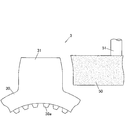
- FIG. 9 is a diagram showing the tripod member 3 and the grindstone 50 in the grinding process.
- the outer peripheral surface of the grindstone 50 used in the grinding process has a shape corresponding to the finished shape of the vertical section of the tripod shaft portion 31.
- the grindstone 50 is pressed around the outer peripheral surface of the tripod shaft portion 31 while rotating around the drive shaft 51, and the outer peripheral surface is ground by rotating around the tripod shaft portion 31.
- the tripod shaft portion 31 thus ground is parallel to the central axis C1 of the tripod shaft portion 31 and the outer peripheral surface of the cross section including the normal line at the ground portion is shown in FIG. Will draw a curve similar to
- the roller member 4 In the state where the joint angle is zero, as shown by the solid line in FIGS. 1 and 2, the roller member 4 is positioned on the base side of the tripod shaft portion 31, and torque transmission on one side of the tripod shaft portion 31 in the torque transmission direction is performed. The surface 31c and the second tapered portion 42b of the inner roller 42 come into contact with each other to transmit torque. In this state, even if the outer race 2 rotates, the tripod shaft portion 31 and the roller member 4 do not slide.
- the curvature of the torque transmission surface 31c is large at the tip side of the tripod shaft portion 31, the area of the contact region is smaller and the surface pressure is higher than when the joint angle is zero, but the torque transmission surface 31c is as described above. Is larger than the distance from the central axis C1 of the linear portion 31a, the surface pressure is suppressed as compared with the case where the tripod shaft portion is formed in a spherical shape as described in Patent Document 1, for example.
- a torque transmission surface 31c having a curved portion 31b that narrows toward the tip end side of the tripod shaft portion 31, and a second taper portion 42b of the inner roller 42 that also decreases in inner diameter toward the tip end side of the tripod shaft portion 31. And the torque is transmitted, so that the tripod shaft portion 31 and the inner roller 42 are in contact with each other over a wider area than when the inner peripheral surface of the inner roller 42 is cylindrical.
- FIG. 10 shows a contact region between the second tapered portion 42b and the torque transmission surface 31c when the inner peripheral surface of the inner roller 42 is viewed from the central axis C1 side of the tripod shaft portion 31 for explaining this effect.
- the contact area is more on the tip side of the tripod shaft portion 31 than when the inner peripheral surface of the inner roller is cylindrical ( Move to the upper side of the figure.
- region does not lack and both members contact in an elliptical contact area
- the surface pressure at the time of torque transmission can be reduced, and as a result, high strength, high durability, or downsizing can be realized.
- the second taper portion 42b of the inner roller 42 extends toward the base side of the tripod shaft portion 31, and a cone angle larger than the cone angle of the second taper portion 42b is formed on the inner end face 422 side of the second taper portion 42b.
- a third taper portion 42c having the shape is formed. That is, since the inner diameter of the inner peripheral surface of the inner roller 42 increases toward the base side of the tripod shaft portion 31, on the torque non-transmission side that does not transmit torque, on both sides of the torque transmission direction of the tripod shaft portion 31. Generation of contact between the tripod shaft portion 31 and the inner roller 42 can be suppressed.
- the roller member near the root of the tripod shaft portion 31 on the torque non-transmission side with the swing of the tripod member 3 with respect to the roller member 4. 4 may easily occur, and the occurrence of this contact may increase the resistance during swinging.
- contact on the torque non-transmission side can be avoided or contacted. Since the surface pressure of the contact portion can be lowered, the swing between the tripod member 3 and the roller member 4 becomes smoother.
- the tripod shaft portion 31 is thickest at the base side and becomes narrower toward the tip end portion, forging is easy and the life of the forging die is extended. That is, for example, when the tripod shaft portion is spherical like the tripod constant velocity joint described in Patent Document 1, it is necessary to flow the material so as to swell outward in the forging die, For this purpose, a large load is required, but in the processing of the tripod member 3 according to the present embodiment, forging can be performed with a relatively small load. Further, since the surface shape of the tripod shaft portion 31 is uniform in the longitudinal section along the central axis C1, it can be easily ground with a grindstone.
- the tripod type constant velocity joint of the present invention has been described based on the embodiments.
- the present invention is not limited to the above embodiments, and may be implemented in various modes without departing from the gist thereof.
- the following modifications are possible.
- the region that contacts the tripod shaft portion 31 on the inner peripheral surface of the inner roller 42 and transmits torque is not a conical surface having a linear cross section, but a curved surface having a curved cross section and bulging radially outward. Good.
- An example of forming the inner roller 42 in this way is shown in FIG.
- the contact surface that contacts the torque transmission surface 31c of the tripod shaft portion 31 is formed by a curved reduced diameter portion 42b1 whose inner diameter decreases from the inner end surface 422 side toward the outer end surface 421 side.
- the curvature of the curved reduced diameter portion 42b1 is formed larger than the curvature of the torque transmission surface 31c.
- the first tapered portion 42a of the inner roller 42 may not be provided.
- the second taper portion 42b or the curved reduced diameter portion 42b1 reaches the outer end surface 421 side.
- the entire part may be constituted by the curved part 31b.
- a tripod constant velocity joint is configured as follows. That is, the tripod shaft portion has a torque transmission surface having a curved shape whose distance from the central axis becomes shorter from the root side toward the tip side, and the roller member is directed from the root side of the tripod shaft portion toward the tip side.
- the torque transmission surface is brought into contact with a contact surface having a smaller inner diameter.
- the scissor roller member may be formed in a conical shape whose diameter is reduced toward the tip side of the tripod shaft portion, and the cone angle may be 0.5 degrees or more. Thereby, the effect of this invention can be show
- the saddle tripod shaft portion may be formed by a curved line having a curvature that increases from the root side toward the tip side in the shape of the torque transmission surface in the longitudinal section including the central axis.
- the curvature radius of the torque transmission surface in the longitudinal section of the tripod shaft portion is preferably larger than the distance between the root side end portion of the torque transmission surface and the center axis of the tripod shaft portion.
- the saddle tripod shaft portion preferably has a width in the rotation axis direction smaller than a width in the torque transmission direction in a cross section orthogonal to the central axis.
- An end surface corresponding to the base side of the tripod shaft portion of the roller member may be formed with an inclined surface having a larger inclination angle than the contact surface with the tripod shaft portion with respect to the central axis of the roller member and extending toward the root. . Thereby, unnecessary interference between the roller member and the tripod shaft portion can be avoided.
Landscapes
- Engineering & Computer Science (AREA)
- General Engineering & Computer Science (AREA)
- Mechanical Engineering (AREA)
- Rolling Contact Bearings (AREA)
- Friction Gearing (AREA)
Abstract
L'invention porte sur un joint homocinétique de type tripode, apte à réduire la pression de contact sur un élément de tripode au moment d'une transmission de couple. Le joint homocinétique de type tripode (1) comprend un élément de tripode (3) ayant trois arbres de tripode radiaux (31), chaque arbre ayant une surface incurvée de transmission de couple (31c) configurée de telle sorte que la distance de la surface à partir de son centre (C1) se réduit graduellement de l'extrémité proximale à l'extrémité distale, un élément de rouleau annulaire (4) inséré de façon à pouvoir osciller dans l'arbre de tripode (31), et ayant une surface de contact (42b) en contact avec la surface de transmission de couple (31c), la surface de contact ayant un diamètre interne qui diminue graduellement à partir du côté proximal vers le côté distal de l'arbre de tripode (31), et une piste externe (2) qui reçoit l'élément de tripode (3) et l'élément de rouleau (4) et qui a des parties cylindriques comportant une rainure de guidage (20a, 20b) qui guide l'élément de rouleau (4) dans la direction d'un axe de rotation (O1).
Applications Claiming Priority (2)
| Application Number | Priority Date | Filing Date | Title |
|---|---|---|---|
| JP2009143507A JP2011001974A (ja) | 2009-06-16 | 2009-06-16 | トリポード型等速ジョイント |
| JP2009-143507 | 2009-06-16 |
Publications (1)
| Publication Number | Publication Date |
|---|---|
| WO2010146958A1 true WO2010146958A1 (fr) | 2010-12-23 |
Family
ID=43356279
Family Applications (1)
| Application Number | Title | Priority Date | Filing Date |
|---|---|---|---|
| PCT/JP2010/058438 Ceased WO2010146958A1 (fr) | 2009-06-16 | 2010-05-19 | Joint homocinétique de type tripode |
Country Status (2)
| Country | Link |
|---|---|
| JP (1) | JP2011001974A (fr) |
| WO (1) | WO2010146958A1 (fr) |
Cited By (2)
| Publication number | Priority date | Publication date | Assignee | Title |
|---|---|---|---|---|
| WO2022202421A1 (fr) * | 2021-03-24 | 2022-09-29 | Ntn株式会社 | Joint homocinétique de type tripode |
| WO2023032631A1 (fr) * | 2021-09-03 | 2023-03-09 | Ntn株式会社 | Joint homocinétique de type tripode |
Families Citing this family (2)
| Publication number | Priority date | Publication date | Assignee | Title |
|---|---|---|---|---|
| JP6152650B2 (ja) * | 2013-02-05 | 2017-06-28 | 株式会社ジェイテクト | ダブルローラタイプのトリポード型等速ジョイント |
| DE102013106868B3 (de) * | 2013-07-01 | 2014-10-30 | Gkn Driveline International Gmbh | Gelenkinnenteil sowie Rollenkörper eines Tripode-Gleichlaufgelenks |
Citations (3)
| Publication number | Priority date | Publication date | Assignee | Title |
|---|---|---|---|---|
| JPS4990747U (fr) * | 1972-11-30 | 1974-08-06 | ||
| JP2001280358A (ja) * | 2000-03-31 | 2001-10-10 | Ntn Corp | 等速自在継手 |
| JP2007327617A (ja) * | 2006-06-09 | 2007-12-20 | Jtekt Corp | トリポード型等速ジョイント |
-
2009
- 2009-06-16 JP JP2009143507A patent/JP2011001974A/ja active Pending
-
2010
- 2010-05-19 WO PCT/JP2010/058438 patent/WO2010146958A1/fr not_active Ceased
Patent Citations (3)
| Publication number | Priority date | Publication date | Assignee | Title |
|---|---|---|---|---|
| JPS4990747U (fr) * | 1972-11-30 | 1974-08-06 | ||
| JP2001280358A (ja) * | 2000-03-31 | 2001-10-10 | Ntn Corp | 等速自在継手 |
| JP2007327617A (ja) * | 2006-06-09 | 2007-12-20 | Jtekt Corp | トリポード型等速ジョイント |
Cited By (4)
| Publication number | Priority date | Publication date | Assignee | Title |
|---|---|---|---|---|
| WO2022202421A1 (fr) * | 2021-03-24 | 2022-09-29 | Ntn株式会社 | Joint homocinétique de type tripode |
| WO2023032631A1 (fr) * | 2021-09-03 | 2023-03-09 | Ntn株式会社 | Joint homocinétique de type tripode |
| JP2023037300A (ja) * | 2021-09-03 | 2023-03-15 | Ntn株式会社 | トリポード型等速自在継手 |
| JP7680914B2 (ja) | 2021-09-03 | 2025-05-21 | Ntn株式会社 | トリポード型等速自在継手 |
Also Published As
| Publication number | Publication date |
|---|---|
| JP2011001974A (ja) | 2011-01-06 |
Similar Documents
| Publication | Publication Date | Title |
|---|---|---|
| CN103069184B (zh) | 滑动式等速万向接头 | |
| JP4541203B2 (ja) | トリポード型等速自在継手 | |
| WO2010146958A1 (fr) | Joint homocinétique de type tripode | |
| US7473181B2 (en) | Tripod type constant velocity universal joint | |
| KR20220049931A (ko) | 등속 조인트 | |
| US7462106B2 (en) | Constant velocity universal joint | |
| CN101688562B (zh) | 滑动式三球销型等速万向节 | |
| JP2010255801A (ja) | トリポード型等速ジョイント | |
| JP4973930B2 (ja) | 摺動式トリポード形等速ジョイント | |
| US20100273561A1 (en) | Tripod-shaped constant-velocity universal joint | |
| KR20140055632A (ko) | 트라이포드 조인트 | |
| JP5760560B2 (ja) | 摺動式トリポード型等速ジョイント | |
| JP2008175371A (ja) | 摺動式トリポード形等速ジョイント | |
| JP4602177B2 (ja) | 等速自在継手 | |
| JP2007309366A (ja) | 等速ジョイント | |
| CN107120358B (zh) | 等速万向节 | |
| JP2001330050A (ja) | トリポード型等速自在継手 | |
| JP4973929B2 (ja) | 摺動式トリポード形等速ジョイントおよびそれを含むジョイント | |
| JP4891652B2 (ja) | 等速ジョイント | |
| JPWO2008111519A1 (ja) | 摺動式トリポード形等速ジョイント | |
| JP2007327617A (ja) | トリポード型等速ジョイント | |
| JP2010014198A (ja) | 摺動式トリポード型等速ジョイント | |
| KR100834214B1 (ko) | 트라이포드식 등속조인트 | |
| JP2006283831A (ja) | 等速自在継手 | |
| JP2008164128A (ja) | 摺動式トリポード形等速ジョイント |
Legal Events
| Date | Code | Title | Description |
|---|---|---|---|
| 121 | Ep: the epo has been informed by wipo that ep was designated in this application |
Ref document number: 10789333 Country of ref document: EP Kind code of ref document: A1 |
|
| NENP | Non-entry into the national phase |
Ref country code: DE |
|
| 122 | Ep: pct application non-entry in european phase |
Ref document number: 10789333 Country of ref document: EP Kind code of ref document: A1 |