WO2010147076A1 - Pneumatique très résistant - Google Patents
Pneumatique très résistant Download PDFInfo
- Publication number
- WO2010147076A1 WO2010147076A1 PCT/JP2010/060025 JP2010060025W WO2010147076A1 WO 2010147076 A1 WO2010147076 A1 WO 2010147076A1 JP 2010060025 W JP2010060025 W JP 2010060025W WO 2010147076 A1 WO2010147076 A1 WO 2010147076A1
- Authority
- WO
- WIPO (PCT)
- Prior art keywords
- rib
- groove
- circumferential
- tire
- shoulder
- Prior art date
- Legal status (The legal status is an assumption and is not a legal conclusion. Google has not performed a legal analysis and makes no representation as to the accuracy of the status listed.)
- Ceased
Links
Images



Classifications
-
- B—PERFORMING OPERATIONS; TRANSPORTING
- B60—VEHICLES IN GENERAL
- B60C—VEHICLE TYRES; TYRE INFLATION; TYRE CHANGING; CONNECTING VALVES TO INFLATABLE ELASTIC BODIES IN GENERAL; DEVICES OR ARRANGEMENTS RELATED TO TYRES
- B60C11/00—Tyre tread bands; Tread patterns; Anti-skid inserts
- B60C11/03—Tread patterns
- B60C11/04—Tread patterns in which the raised area of the pattern consists only of continuous circumferential ribs, e.g. zig-zag
-
- B—PERFORMING OPERATIONS; TRANSPORTING
- B60—VEHICLES IN GENERAL
- B60C—VEHICLE TYRES; TYRE INFLATION; TYRE CHANGING; CONNECTING VALVES TO INFLATABLE ELASTIC BODIES IN GENERAL; DEVICES OR ARRANGEMENTS RELATED TO TYRES
- B60C11/00—Tyre tread bands; Tread patterns; Anti-skid inserts
- B60C11/03—Tread patterns
- B60C11/04—Tread patterns in which the raised area of the pattern consists only of continuous circumferential ribs, e.g. zig-zag
- B60C11/042—Tread patterns in which the raised area of the pattern consists only of continuous circumferential ribs, e.g. zig-zag further characterised by the groove cross-section
-
- B—PERFORMING OPERATIONS; TRANSPORTING
- B60—VEHICLES IN GENERAL
- B60C—VEHICLE TYRES; TYRE INFLATION; TYRE CHANGING; CONNECTING VALVES TO INFLATABLE ELASTIC BODIES IN GENERAL; DEVICES OR ARRANGEMENTS RELATED TO TYRES
- B60C11/00—Tyre tread bands; Tread patterns; Anti-skid inserts
- B60C11/03—Tread patterns
- B60C11/04—Tread patterns in which the raised area of the pattern consists only of continuous circumferential ribs, e.g. zig-zag
- B60C11/042—Tread patterns in which the raised area of the pattern consists only of continuous circumferential ribs, e.g. zig-zag further characterised by the groove cross-section
- B60C11/047—Tread patterns in which the raised area of the pattern consists only of continuous circumferential ribs, e.g. zig-zag further characterised by the groove cross-section the groove bottom comprising stone trapping protection elements, e.g. ribs
-
- B—PERFORMING OPERATIONS; TRANSPORTING
- B60—VEHICLES IN GENERAL
- B60C—VEHICLE TYRES; TYRE INFLATION; TYRE CHANGING; CONNECTING VALVES TO INFLATABLE ELASTIC BODIES IN GENERAL; DEVICES OR ARRANGEMENTS RELATED TO TYRES
- B60C11/00—Tyre tread bands; Tread patterns; Anti-skid inserts
- B60C11/03—Tread patterns
- B60C2011/0337—Tread patterns characterised by particular design features of the pattern
- B60C2011/0339—Grooves
- B60C2011/0341—Circumferential grooves
- B60C2011/0348—Narrow grooves, i.e. having a width of less than 4 mm
-
- B—PERFORMING OPERATIONS; TRANSPORTING
- B60—VEHICLES IN GENERAL
- B60C—VEHICLE TYRES; TYRE INFLATION; TYRE CHANGING; CONNECTING VALVES TO INFLATABLE ELASTIC BODIES IN GENERAL; DEVICES OR ARRANGEMENTS RELATED TO TYRES
- B60C11/00—Tyre tread bands; Tread patterns; Anti-skid inserts
- B60C11/03—Tread patterns
- B60C2011/0337—Tread patterns characterised by particular design features of the pattern
- B60C2011/0339—Grooves
- B60C2011/0341—Circumferential grooves
- B60C2011/0351—Shallow grooves, i.e. having a depth of less than 50% of other grooves
-
- B—PERFORMING OPERATIONS; TRANSPORTING
- B60—VEHICLES IN GENERAL
- B60C—VEHICLE TYRES; TYRE INFLATION; TYRE CHANGING; CONNECTING VALVES TO INFLATABLE ELASTIC BODIES IN GENERAL; DEVICES OR ARRANGEMENTS RELATED TO TYRES
- B60C11/00—Tyre tread bands; Tread patterns; Anti-skid inserts
- B60C11/03—Tread patterns
- B60C2011/0337—Tread patterns characterised by particular design features of the pattern
- B60C2011/0339—Grooves
- B60C2011/0358—Lateral grooves, i.e. having an angle of 45 to 90 degees to the equatorial plane
- B60C2011/036—Narrow grooves, i.e. having a width of less than 3 mm
-
- B—PERFORMING OPERATIONS; TRANSPORTING
- B60—VEHICLES IN GENERAL
- B60C—VEHICLE TYRES; TYRE INFLATION; TYRE CHANGING; CONNECTING VALVES TO INFLATABLE ELASTIC BODIES IN GENERAL; DEVICES OR ARRANGEMENTS RELATED TO TYRES
- B60C11/00—Tyre tread bands; Tread patterns; Anti-skid inserts
- B60C11/03—Tread patterns
- B60C2011/0337—Tread patterns characterised by particular design features of the pattern
- B60C2011/0339—Grooves
- B60C2011/0358—Lateral grooves, i.e. having an angle of 45 to 90 degees to the equatorial plane
- B60C2011/0362—Shallow grooves, i.e. having a depth of less than 50% of other grooves
-
- B—PERFORMING OPERATIONS; TRANSPORTING
- B60—VEHICLES IN GENERAL
- B60C—VEHICLE TYRES; TYRE INFLATION; TYRE CHANGING; CONNECTING VALVES TO INFLATABLE ELASTIC BODIES IN GENERAL; DEVICES OR ARRANGEMENTS RELATED TO TYRES
- B60C11/00—Tyre tread bands; Tread patterns; Anti-skid inserts
- B60C11/03—Tread patterns
- B60C2011/0337—Tread patterns characterised by particular design features of the pattern
- B60C2011/0339—Grooves
- B60C2011/0374—Slant grooves, i.e. having an angle of about 5 to 35 degrees to the equatorial plane
-
- B—PERFORMING OPERATIONS; TRANSPORTING
- B60—VEHICLES IN GENERAL
- B60C—VEHICLE TYRES; TYRE INFLATION; TYRE CHANGING; CONNECTING VALVES TO INFLATABLE ELASTIC BODIES IN GENERAL; DEVICES OR ARRANGEMENTS RELATED TO TYRES
- B60C11/00—Tyre tread bands; Tread patterns; Anti-skid inserts
- B60C11/03—Tread patterns
- B60C2011/0337—Tread patterns characterised by particular design features of the pattern
- B60C2011/0339—Grooves
- B60C2011/0381—Blind or isolated grooves
-
- B—PERFORMING OPERATIONS; TRANSPORTING
- B60—VEHICLES IN GENERAL
- B60C—VEHICLE TYRES; TYRE INFLATION; TYRE CHANGING; CONNECTING VALVES TO INFLATABLE ELASTIC BODIES IN GENERAL; DEVICES OR ARRANGEMENTS RELATED TO TYRES
- B60C11/00—Tyre tread bands; Tread patterns; Anti-skid inserts
- B60C11/03—Tread patterns
- B60C2011/0337—Tread patterns characterised by particular design features of the pattern
- B60C2011/0339—Grooves
- B60C2011/0381—Blind or isolated grooves
- B60C2011/0383—Blind or isolated grooves at the centre of the tread
-
- B—PERFORMING OPERATIONS; TRANSPORTING
- B60—VEHICLES IN GENERAL
- B60C—VEHICLE TYRES; TYRE INFLATION; TYRE CHANGING; CONNECTING VALVES TO INFLATABLE ELASTIC BODIES IN GENERAL; DEVICES OR ARRANGEMENTS RELATED TO TYRES
- B60C11/00—Tyre tread bands; Tread patterns; Anti-skid inserts
- B60C11/03—Tread patterns
- B60C2011/0337—Tread patterns characterised by particular design features of the pattern
- B60C2011/0386—Continuous ribs
-
- B—PERFORMING OPERATIONS; TRANSPORTING
- B60—VEHICLES IN GENERAL
- B60C—VEHICLE TYRES; TYRE INFLATION; TYRE CHANGING; CONNECTING VALVES TO INFLATABLE ELASTIC BODIES IN GENERAL; DEVICES OR ARRANGEMENTS RELATED TO TYRES
- B60C11/00—Tyre tread bands; Tread patterns; Anti-skid inserts
- B60C11/03—Tread patterns
- B60C2011/0337—Tread patterns characterised by particular design features of the pattern
- B60C2011/0386—Continuous ribs
- B60C2011/039—Continuous ribs provided at the shoulder portion
-
- B—PERFORMING OPERATIONS; TRANSPORTING
- B60—VEHICLES IN GENERAL
- B60C—VEHICLE TYRES; TYRE INFLATION; TYRE CHANGING; CONNECTING VALVES TO INFLATABLE ELASTIC BODIES IN GENERAL; DEVICES OR ARRANGEMENTS RELATED TO TYRES
- B60C11/00—Tyre tread bands; Tread patterns; Anti-skid inserts
- B60C11/03—Tread patterns
- B60C2011/0337—Tread patterns characterised by particular design features of the pattern
- B60C2011/0386—Continuous ribs
- B60C2011/0397—Sacrificial ribs, i.e. ribs recessed from outer tread contour
-
- B—PERFORMING OPERATIONS; TRANSPORTING
- B60—VEHICLES IN GENERAL
- B60C—VEHICLE TYRES; TYRE INFLATION; TYRE CHANGING; CONNECTING VALVES TO INFLATABLE ELASTIC BODIES IN GENERAL; DEVICES OR ARRANGEMENTS RELATED TO TYRES
- B60C11/00—Tyre tread bands; Tread patterns; Anti-skid inserts
- B60C11/03—Tread patterns
- B60C11/12—Tread patterns characterised by the use of narrow slits or incisions, e.g. sipes
- B60C11/1236—Tread patterns characterised by the use of narrow slits or incisions, e.g. sipes with special arrangements in the tread pattern
- B60C2011/1245—Tread patterns characterised by the use of narrow slits or incisions, e.g. sipes with special arrangements in the tread pattern being arranged in crossing relation, e.g. sipe mesh
-
- B—PERFORMING OPERATIONS; TRANSPORTING
- B60—VEHICLES IN GENERAL
- B60C—VEHICLE TYRES; TYRE INFLATION; TYRE CHANGING; CONNECTING VALVES TO INFLATABLE ELASTIC BODIES IN GENERAL; DEVICES OR ARRANGEMENTS RELATED TO TYRES
- B60C11/00—Tyre tread bands; Tread patterns; Anti-skid inserts
- B60C11/03—Tread patterns
- B60C11/13—Tread patterns characterised by the groove cross-section, e.g. for buttressing or preventing stone-trapping
- B60C11/1307—Tread patterns characterised by the groove cross-section, e.g. for buttressing or preventing stone-trapping with special features of the groove walls
- B60C2011/133—Tread patterns characterised by the groove cross-section, e.g. for buttressing or preventing stone-trapping with special features of the groove walls comprising recesses
-
- B—PERFORMING OPERATIONS; TRANSPORTING
- B60—VEHICLES IN GENERAL
- B60C—VEHICLE TYRES; TYRE INFLATION; TYRE CHANGING; CONNECTING VALVES TO INFLATABLE ELASTIC BODIES IN GENERAL; DEVICES OR ARRANGEMENTS RELATED TO TYRES
- B60C2200/00—Tyres specially adapted for particular applications
- B60C2200/06—Tyres specially adapted for particular applications for heavy duty vehicles
Definitions
- the present invention provides a shoulder rib provided in a tread shoulder portion, extending in the tire circumferential direction, adjacent to the shoulder rib via a circumferential groove, and provided closer to the tire equator line than the shoulder rib and extending in the tire circumferential direction.
- the present invention relates to a heavy duty tire provided with side ribs and uneven wear absorbing ribs that are provided in the circumferential grooves and extend in the tire circumferential direction and are located on the inner side in the tire radial direction from the treads of the shoulder ribs and the center side ribs.
- an object of the present invention is to provide a heavy duty tire that further improves wet performance during turning while suppressing uneven wear of the tread shoulder portion.
- the present invention has the following features.
- the first feature of the present invention is that shoulder ribs (shoulder ribs A1, shoulder ribs A5) provided in the tread shoulder portion and extending in the tire circumferential direction (tire circumferential direction R), and circumferential grooves (for example, circumferential direction) Center-side ribs (second rib A2, second rib A4) that are adjacent to the shoulder ribs through the grooves 110) and are closer to the tire equator line (tire equator line CL) than the shoulder ribs and extend in the tire circumferential direction.
- An uneven wear absorbing rib (for example, an uneven wear absorbing rib B1) provided in the circumferential groove and extending in the tire circumferential direction and positioned on the inner side in the tire radial direction from the tread surface of the shoulder rib and the center side rib; , A heavy load tire (heavy load tire 1), wherein the center side rib extends in a tire circumferential direction, and the circumferential groove A circumferential narrow groove (for example, the circumferential narrow groove 10) having a narrow groove width is formed, and the circumferential narrow groove is based on the center in the tread width direction (tread width direction W) of the center side rib.
- the gist is that it is formed outside when the vehicle is mounted.
- the circumferential narrow groove is formed in the center side rib whose contact length becomes longer when turning. For this reason, while increasing the edge part at the time of turning, it can suppress that edge pressure concentrates on tread shoulder parts, such as a shoulder rib. Moreover, since the circumferential narrow groove extends in the tire circumferential direction, drainage can be improved.
- the second feature of the present invention is related to the first feature of the present invention, wherein the center-side rib is formed with an intersecting narrow groove (intersecting narrow groove 30) intersecting the circumferential narrow groove.
- a third feature of the present invention relates to the second feature of the present invention, wherein the intersecting narrow groove includes a lateral groove portion (lateral groove portion 32) extending along a tread width direction (tread width direction W), and a tire circumferential direction. And a vertical groove portion (longitudinal groove portion 34) extending along the line.
- a fourth feature of the present invention relates to the second or third feature of the present invention, wherein the center-side rib has a narrow groove (narrow groove) extending in the tread width direction and having a groove width narrower than the circumferential groove. 20) is formed, and in the tread surface view, with respect to the center in the tread width direction of the center side rib, the circumferential narrow groove on the outside of the center side rib when the vehicle is mounted, the narrow groove, and the intersecting narrow groove.
- the gist of the present invention is that the total area with the groove is set to 1.5 times or more than the total area of the narrow groove and the intersecting narrow groove on the vehicle inner side of the center side rib.
- the fifth feature of the present invention relates to the third or fourth feature of the present invention, and is summarized in that the crossing narrow groove is formed in an L shape.
- a sixth feature of the present invention relates to any one of the second to fifth features of the present invention, and is summarized in that any end portion of the intersecting narrow groove communicates with the circumferential groove. .
- a seventh feature of the present invention relates to any one of the first to sixth features of the present invention, wherein the center side rib communicates with the circumferential groove and intersects with the circumferential narrow groove.
- a plurality of intersecting transverse grooves (for example, a plurality of intersecting transverse grooves 142) are formed, and the plurality of intersecting transverse grooves are formed at a predetermined interval (interval P2) in the tire circumferential direction.
- FIG. 1 is a development view of a pattern provided on a tread portion of a heavy duty tire according to an embodiment of the present invention.
- FIG. 2 is a partial cross-sectional perspective view of the tread portion of the heavy duty tire according to the embodiment of the present invention.
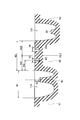
- 3 is a cross-sectional view taken along the line AA in FIG.
- FIG. 4 is a partial development view of a pattern provided on a tread portion of a heavy duty tire according to a modification of the embodiment of the present invention.
- FIG. 1 is a development view of a tread constituting the heavy load tire 1 according to the embodiment of the present invention.
- FIG. 2 is a partial cross-sectional perspective view of the tread portion of the heavy duty tire 1 according to the embodiment of the present invention.
- FIG. 3 is an AA cross-sectional view of the tread portion of the heavy duty tire 1 according to the embodiment of the present invention.
- the heavy load tire 1 is attached to a vehicle mainly traveling straight, such as a truck or a bus.
- the heavy load tire 1 includes a plurality of ribs extending along the tire circumferential direction R.
- the heavy load tire 1 includes a shoulder rib A1, a second rib A2, a center rib A3, a second rib A4, a shoulder rib A5, an uneven wear absorbing rib B1, and an uneven wear absorbing rib B2. Further, the heavy load tire 1 is formed with a circumferential groove 110, a circumferential groove 112, a circumferential groove 114, and a circumferential groove 116 extending along the tire circumferential direction R between the plurality of ribs.
- the shoulder rib A1 and the shoulder rib A5 are provided in the tread shoulder portion and extend in the tire circumferential direction R.
- a lateral groove 130 extending in the tread width direction W is formed in the shoulder rib A1 and the shoulder rib A5.
- the tread shoulder portion is a region disposed on the surface of the heavy load tire 1 between the tread portion that contacts the road surface and the sidewall portion.
- the second rib A2 and the second rib A4 constitute a center side rib.
- the second rib A2 is adjacent to the shoulder rib A1 via the circumferential groove 110, is provided closer to the tire equator line CL than the shoulder rib A1, and extends in the tire circumferential direction R.
- the tire equator line CL is a line passing through the center in the tread width direction W of the heavy load tire 1.
- the second rib A4 is adjacent to the shoulder rib A5 via the circumferential groove 116, is provided closer to the tire equator line CL than the shoulder rib A5, and extends in the tire circumferential direction R.
- the center rib A3 is provided on the tire equator line CL and extends in the tire circumferential direction R.
- the heavy-duty tire 1 includes four circumferential grooves and five ribs defined by the four circumferential grooves. Although not limited, although not shown, it is possible to apply the configuration of the present application even if it is formed so as to include three circumferential grooves and four ribs partitioned by the three circumferential grooves.
- the uneven wear absorbing rib B1 is provided in the circumferential groove 110, extends in the tire circumferential direction R, and is located on the inner side in the tire radial direction from the treads of the shoulder ribs A1, A5, the second ribs A2, A4, and the center rib A3. To do.
- the distance D2 from the uneven wear absorbing rib B1 to the treads of the shoulder rib A1 and the second rib A2 is set to 1.0 mm to 15.0 mm.
- the uneven wear absorbing rib B1 is formed on the outer side when the vehicle is mounted with reference to the center of the circumferential groove 110 in the tread width direction W.
- the uneven wear absorbing rib B2 provided in the circumferential groove 116 has the same characteristics as the uneven wear absorbing rib B1, and therefore details thereof are omitted.
- a lateral groove extending along the tread width direction W is formed in each rib.
- the lateral groove 130 is formed in the shoulder rib A1 and the shoulder rib A5.
- a lateral groove 20 is formed in the second rib A2 and the second rib A4.
- a lateral groove 120 is formed in the center rib A3.
- the length W2 of the second rib A2 and the second rib A4 in the tread width direction W is set to 65 to 90% or less with respect to the length of the shoulder rib A1 and the shoulder rib A5 in the tread width direction W.
- the lateral groove 20, the lateral groove 120, and the lateral groove 130 extend in the tread width direction W, have a narrower groove width than the circumferential groove, and are shallower in the tire radial direction than the circumferential groove. Further, the lateral groove 120 formed in the center rib A3 is configured to terminate in the land portion.
- a sipe 20S is provided in the lateral groove 20 formed in the second rib A2 and the second rib A4, and a sipe 120S (not shown) is provided in the lateral groove 120 formed in the center rib A3.
- the sipe 20S has a tire diameter compared to other portions of the sipe 20S at the opening portion where the circumferential grooves 112, 114 and the lateral groove 20 communicate with each other and at the center portion of the second rib A2 and the second rib A4 in the tread width direction W. It is formed so that the depth in the direction is deep.
- the sipe 120S has a tire radial depth at the opening portion where the circumferential grooves 112, 114 and the lateral groove 120 communicate with each other and at the center portion in the tread width direction W of the center rib A3 as compared with other portions of the sipe 120S. It is formed to be deep.
- the depth in the tire radial direction D of the circumferential groove 110, the circumferential groove 112, the circumferential groove 114, and the circumferential groove 116 is formed to be 7 to 22 mm.
- a stone biting prevention rib 60 is formed in the circumferential groove 112 and the circumferential groove 114.
- the stone debris prevention rib 60 is provided in each of the circumferential groove 112 and the circumferential groove 114 and extends in the tire circumferential direction R, and more than the treads of the shoulder ribs A1, A5, the second ribs A2, A4, and the center rib A3. Located inside the tire radial direction.
- circumferential narrow groove 10 extending in the tire circumferential direction R and having a narrower groove width than the circumferential groove 110 is formed.
- the circumferential narrow groove 12 formed in the second rib A4 has the same characteristics as the circumferential narrow groove 10. For this reason, detailed description about the circumferential narrow groove is omitted.
- the second rib A2 includes a second small rib A21 located on the outer side when the vehicle is mounted and a second small rib positioned on the inner side when the vehicle is mounted, with reference to the center CL2 in the tread width direction W of the second rib A2. A22.
- the circumferential narrow groove 10 is formed on the outer side when the vehicle is mounted with reference to the center CL2 in the tread width direction W of the second rib A2. Specifically, in the tread width direction W, the distance W3 from the outer end of the second rib A2 when the vehicle is mounted to the center of the circumferential narrow groove 10 is 1/2 with respect to the length W2 of the second rib A2. The length is set to 6 to 1/2.
- the depth D3 in the tire radial direction of the circumferential narrow groove 10 is set to 0.5 mm to 3.0 mm on the inner side in the tire radial direction from the tread surface of the second rib A2. That is, the circumferential narrow groove 10 is formed so that the depth in the tire radial direction is shallower than the circumferential grooves 110, 112, 114, 116.
- a plurality of intersecting narrow grooves 30 intersecting the circumferential narrow groove 10 are formed in the second rib A2.
- the intersecting narrow groove 30 includes a lateral groove portion 32 and a vertical groove portion 34.
- One end of the intersecting narrow groove 30 communicates with the circumferential groove. That is, the second rib A ⁇ b> 2 is formed with a plurality of intersecting narrow grooves 30 that communicate with the circumferential grooves and intersect with the circumferential narrow grooves 10.
- the plurality of intersecting narrow grooves 30 are formed at a predetermined interval P1 in the tire circumferential direction R.
- the total area of the circumferential narrow groove 10, the lateral groove 20, and the intersecting narrow groove 30 in the second small rib A21 is relative to the total area of the lateral groove 20 and the intersecting narrow groove 30 in the second small rib A22. Is set to 1.5 times or more.
- the lateral groove 32 extends linearly along the tread width direction W.
- the term “along the tread width direction W” indicates that the inclination is in the range of 0 to less than 45 ° with respect to the straight line along the tread width direction W.
- One end of the lateral groove portion 32 communicates with the circumferential groove 110, and the other end communicates with the longitudinal groove portion 34.
- the longitudinal groove portion 34 extends linearly along the tire circumferential direction R.
- the term “along the tire circumferential direction R” indicates that the vehicle is inclined in a range of 0 to less than 45 ° with respect to a straight line along the tire circumferential direction R.
- One end of the vertical groove portion 34 communicates with the horizontal groove 20, and the other end communicates with the horizontal groove portion 32.
- the end of the lateral groove 32 extending linearly along the tread width direction W and the end of the longitudinal groove 34 extending linearly along the tire circumferential direction R are continuous. 30 is formed in an L shape.
- the depth D4 in the tire radial direction of the intersecting narrow groove 30 is set to 0.5 mm to 3.0 mm on the inner side in the tire radial direction from the tread surface of the second rib A2. That is, the intersecting narrow groove 30 is formed so that the depth in the tire radial direction is shallower than the circumferential grooves 110, 112, 114, 116.
- the lateral groove 20 formed in the second rib A2 and the second rib A4 and the lateral groove portion 32 in the intersecting narrow groove 30 are outside the tread width direction W of the circumferential narrow groove 10.
- the direction inclined with respect to the straight line along the tread width direction W is different.
- the lateral groove 20 and the lateral groove portion 32 are inclined in the same direction with respect to a straight line along the tread width direction W on the inner side in the tread width direction W than the circumferential narrow groove 10.
- the lateral groove 20 changes in the direction inclined with respect to the straight line along the tread width direction W on the inner side and the outer side of the tread width direction W with the circumferential narrow groove 10 as a starting point. That is, on the outer side in the tread width direction W than the circumferential narrow groove 10, the lateral groove 20 and the lateral groove portion 32 are formed to incline in opposite directions with respect to a straight line along the tread width direction W.
- the second rib A2 (second rib A4) includes a plurality of intersecting transverse grooves 142 communicating with the circumferential groove 110 or the circumferential groove 112, and a plurality of intersecting transverse grooves. 144 is formed.
- the plurality of intersecting lateral grooves 142 and the plurality of intersecting lateral grooves 144 are formed at a predetermined interval P2 in the tire circumferential direction R.
- a plurality of intersecting lateral grooves 140 communicating with the circumferential groove 110 or the circumferential groove 116 are formed in the shoulder rib A1 and the shoulder rib A5.
- a plurality of intersecting lateral grooves 146 communicating with the circumferential groove 112 or the circumferential groove 114 are formed in the center rib A3.
- the crossing lateral groove 146 formed in the center rib A3 is configured to terminate in the land portion.
- the heavy load tire 1 according to the embodiment described above may be modified as follows.
- symbol is attached
- FIG. 4A is a partial development view of a pattern provided on the tread portion of the heavy duty tire according to the first modification.
- the intersecting narrow groove 30 of the heavy load tire 1 includes the lateral groove portion 32 extending along the tread width direction W and the vertical groove portion 34 extending along the tire circumferential direction R, and is formed in an L shape. Is done. As shown in FIG. 4A, in the first modification, the intersecting narrow grooves 30A are formed in a straight line extending obliquely with respect to the tire circumferential direction R. One end of the intersecting narrow groove 30A communicates with the circumferential groove 110, and the other end communicates with the lateral groove 20A.
- FIG. 4B is a partial development view of a pattern provided on the tread portion of the heavy duty tire according to the second modification.
- the crossing narrow groove 30B in the modified example 2, in the crossing narrow groove 30B, the lateral groove portion 32B extending linearly along the tread width direction W and the vertical groove portion extending linearly along the tire circumferential direction R. Since 34B continues in a substantially vertical shape, the crossing narrow groove 30B is formed in an L shape having a right angle portion.
- FIG. 4C is a partial development view of a pattern provided on the tread portion of the heavy duty tire according to the third modification.
- the intersecting narrow grooves 30C are linear along the tire circumferential direction R and the lateral groove 32C, the lateral groove 32D extending linearly along the tread width direction W.
- a longitudinal groove portion 34 ⁇ / b> C extending in the vertical direction.
- Each heavy load tire has the same configuration except for the circumferential narrow groove. Further, the areas of the circumferential narrow grooves, the intersecting narrow grooves, and the lateral grooves formed in each heavy load tire are set equal.
- the heavy duty tire according to the example has the same configuration as the heavy duty tire 1 according to the embodiment.
- the heavy load tire according to the comparative example 1 is different from the heavy load tire according to the example in that the circumferential narrow groove is formed on the inner side of the vehicle with reference to the center in the tread width direction of the center side rib.
- the heavy load tire according to Comparative Example 2 is different from the heavy load tire according to the example in that the circumferential narrow groove is formed in the shoulder rib.
- the evaluation results of turning performance, braking performance, and uneven wear resistance performance are displayed as a contrast index when the evaluation result of the heavy duty tire according to Comparative Example 1 is 100.
- the contrast index increases as the performance increases.
- the heavy load tire according to the example exhibited superior turning performance while having equivalent uneven wear resistance and braking performance as compared with the heavy load tire according to Comparative Example 1.
- the heavy load tire according to Comparative Example 2 exhibited excellent turning performance as compared with the heavy load tire according to Comparative Example 1, but was inferior in uneven wear resistance.
- the circumferential narrow groove 10 (circumferential narrow groove 12) has the second rib A2 (the ground contact length becomes long when turning) ( The second rib A4) is formed. For this reason, while being able to increase the edge part at the time of turning, it can suppress that edge pressure concentrates on tread shoulder parts, such as shoulder rib A1 (shoulder rib A5). Moreover, since the circumferential direction narrow groove 10 (circumferential direction narrow groove 12) extends in the tire circumferential direction R, drainage can be improved.
- the intersecting narrow groove 30 intersecting the circumferential narrow groove 10 (circumferential narrow groove 12) is formed in the second rib A2 (second rib A4). For this reason, the edge component at the time of turning increases. Accordingly, the braking performance and the like during turning are further improved.
- the intersecting narrow groove 30 includes the lateral groove portion 32 extending along the tread width direction W, the lateral groove portion 32 functions reliably as an edge component during straight traveling. Further, since the intersecting narrow groove 30 includes the vertical groove portion 34 extending along the tire circumferential direction R, the vertical groove portion 34 functions reliably as an edge component during turning. Therefore, according to the intersecting narrow groove 30, the braking performance and the like during straight traveling and turning are reliably improved.
- the second small rib A21 located outside the second rib A2 (second rib A4) when mounted on the vehicle has a higher ground pressure than the second small rib A22 positioned inside the vehicle mounted.
- the total area of the circumferential narrow groove 10, the lateral groove 20, and the intersecting narrow groove 30 in the second small rib A21 is equal to the lateral groove 20 in the second small rib A22 located on the vehicle mounting inner side of the second rib A2 (second rib A4).
- 1.5 times or more of the total area of the intersecting narrow grooves 30 For this reason, while being able to increase the edge part at the time of turning efficiently, drainage can be improved efficiently. Accordingly, wet performance including drainage performance, steering stability performance, and the like during turning can be further improved.
- the intersecting narrow groove 30 is formed in an L shape. That is, since the crossing narrow groove 30 includes the substantially straight lateral groove portion 32, the braking performance and the like during straight traveling are further improved. Further, since the intersecting narrow groove 30 includes the substantially straight vertical groove portion 34, the braking performance and the like during turning are further improved.
- either end of the intersecting narrow groove 30 communicates with the circumferential groove 110 or the circumferential groove 112. For this reason, the water flowing through the intersecting narrow grooves 30 is drained through the circumferential grooves 110 or the circumferential grooves 112. Therefore, the drainage of the heavy load tire 1 is further improved.
- the second rib A2 (second rib A4) is formed with a plurality of intersecting lateral grooves 142 (a plurality of intersecting lateral grooves 144) formed at a predetermined interval P2 in the tire circumferential direction R.
- the braking performance during running is further improved.
- the circumferential narrow groove 10, the lateral grooves 20, 120, 130, and the intersecting narrow groove 30 have a depth in the tire radial direction that is shallower than the circumferential grooves 110, 112, 114, 116. Is formed. For this reason, while being able to suppress the fall of the rigidity of each rib, while improving abrasion resistance, the wet performance in the wear initial stage can be improved.
- the sipe 20S is provided in the lateral groove 20 formed in the second rib A2 and the second rib A4, and the sipe 120S is provided in the lateral groove 120 formed in the center rib A3. ing. For this reason, the wet performance in the last stage of wear of second rib A2, second rib A4, and center rib A3 is securable.
- the sipe 20S includes the other part of the sipe 20S at the opening portion where the circumferential grooves 112, 114 and the lateral groove 20 communicate with each other and the trib width direction W central portion of the second rib A2 and the second rib A4. It is formed so that the depth in the tire radial direction is deeper than the portion.
- the sipe 120S has a depth in the tire radial direction in the opening portion where the circumferential grooves 112, 114 and the lateral groove 120 communicate with each other and in the center portion of the center rib A3 in the tread width direction W as compared with other portions of the sipe 120S. It is formed to be deep.
- the lateral groove 120 and the intersecting lateral groove 146 formed in the center rib A3 are configured to terminate in the land portion. For this reason, the rigidity of the center rib A3 in which the contact pressure with the road surface is higher than other ribs can be ensured. As a result, braking performance and wear resistance performance can be improved.
- the lateral groove 20 formed in the second rib A2 and the second rib A4 and the lateral groove portion 32 in the intersecting narrow groove 30 are tread widths outside the circumferential narrow groove 10 in the tread width direction W.
- the inclination with respect to the straight line along the direction W is different.
- the intersecting narrow groove 30 of the heavy load tire 1 includes the lateral groove portion 32 that extends linearly along the tread width direction W and the vertical groove portion 34 that extends linearly along the tire circumferential direction R. , Formed in an L shape.
- the crossing narrow grooves are not limited to this, and may extend along the tread width direction W or the tire circumferential direction R in a curved shape, a zigzag shape, or a combination thereof in the tread surface view.
- the intersecting narrow groove 30 formed in the second rib A4 and the intersecting narrow groove 30 formed in the second rib A2 are point-symmetrical shapes around an arbitrary point on the tire equator line CL. It is.
- the present invention is not limited to this, and crossed narrow grooves having different shapes may be formed in the second rib A4 and the second rib A2.
- the lateral groove 20, the lateral groove 130, and the lateral groove 120 may be formed in different shapes with reference to the tire equator line CL.
- the sipe 20S is provided in the lateral groove 20 formed in the second rib A2 and the second rib A4, and the sipe 120S is provided in the lateral groove 120 formed in the center rib A3.
- the sipe 20S has a tire radial depth that is deeper at the opening where the circumferential grooves 112, 114 and the lateral groove 20 communicate with each other and the tread width direction W central portion of the second rib A2 and the second rib A4. Is formed. Not only this but the depth of the sipe 20S provided in the horizontal groove 20 and the horizontal groove 120 and the sipe 120S in the tire radial direction may be unified over the entire tread width direction W. Further, the sipe 20S and the sipe 120S may not be provided in the lateral groove 20 and the lateral groove 120.
- the lateral groove 130 is formed in the shoulder rib A1 and the shoulder rib A5, but the lateral groove 130 is not limited to the lateral groove 130, and another lateral groove may be formed.
- sipes may be formed. Preferably, either a lateral groove or a sipe is formed.
- the lateral grooves and sipes formed in the shoulder rib A1 and the shoulder rib A5 are shallower in the tire radial direction than the circumferential grooves 110, 112, 114, and 116. As a result, the rigidity of the shoulder rib A1 and the shoulder rib A5 is increased. If reduction and uneven wear can be suppressed, the shape can be appropriately set.
Landscapes
- Engineering & Computer Science (AREA)
- Mechanical Engineering (AREA)
- Tires In General (AREA)
Abstract
Priority Applications (5)
| Application Number | Priority Date | Filing Date | Title |
|---|---|---|---|
| BRPI1013115-9A BRPI1013115A2 (pt) | 2009-06-15 | 2010-06-14 | pneu para serviço pesado |
| US13/378,248 US9073390B2 (en) | 2009-06-15 | 2010-06-14 | Heavy duty tire |
| EP10789451.1A EP2444257B1 (fr) | 2009-06-15 | 2010-06-14 | Pneumatique très résistant |
| CN201080026337.XA CN102802966B (zh) | 2009-06-15 | 2010-06-14 | 重载用轮胎 |
| JP2011519768A JP6043483B2 (ja) | 2009-06-15 | 2010-06-14 | 重荷重用タイヤ |
Applications Claiming Priority (2)
| Application Number | Priority Date | Filing Date | Title |
|---|---|---|---|
| JP2009-142472 | 2009-06-15 | ||
| JP2009142472 | 2009-06-15 |
Publications (1)
| Publication Number | Publication Date |
|---|---|
| WO2010147076A1 true WO2010147076A1 (fr) | 2010-12-23 |
Family
ID=43356394
Family Applications (1)
| Application Number | Title | Priority Date | Filing Date |
|---|---|---|---|
| PCT/JP2010/060025 Ceased WO2010147076A1 (fr) | 2009-06-15 | 2010-06-14 | Pneumatique très résistant |
Country Status (6)
| Country | Link |
|---|---|
| US (1) | US9073390B2 (fr) |
| EP (1) | EP2444257B1 (fr) |
| JP (1) | JP6043483B2 (fr) |
| CN (1) | CN102802966B (fr) |
| BR (1) | BRPI1013115A2 (fr) |
| WO (1) | WO2010147076A1 (fr) |
Cited By (7)
| Publication number | Priority date | Publication date | Assignee | Title |
|---|---|---|---|---|
| JP2013169886A (ja) * | 2012-02-21 | 2013-09-02 | Bridgestone Corp | タイヤ |
| JP2014151716A (ja) * | 2013-02-06 | 2014-08-25 | Sumitomo Rubber Ind Ltd | 重荷重用空気入りタイヤ |
| WO2016024593A1 (fr) * | 2014-08-12 | 2016-02-18 | 横浜ゴム株式会社 | Pneu |
| WO2016035660A1 (fr) * | 2014-09-05 | 2016-03-10 | 横浜ゴム株式会社 | Pneumatique |
| WO2016035659A1 (fr) * | 2014-09-05 | 2016-03-10 | 横浜ゴム株式会社 | Pneu |
| US10518588B2 (en) | 2014-02-06 | 2019-12-31 | The Yokohama Rubber Co., Ltd. | Pneumatic tire |
| JP2020055427A (ja) * | 2018-10-02 | 2020-04-09 | 住友ゴム工業株式会社 | 重荷重用タイヤ |
Families Citing this family (10)
| Publication number | Priority date | Publication date | Assignee | Title |
|---|---|---|---|---|
| DE102012108384A1 (de) | 2012-09-10 | 2014-03-13 | Continental Reifen Deutschland Gmbh | Fahrzeugluftreifen |
| CN104210317B (zh) * | 2013-06-04 | 2017-07-04 | 风神轮胎股份有限公司 | 一种夏季专用轮胎 |
| USD761196S1 (en) * | 2014-09-25 | 2016-07-12 | The Goodyear Tire & Rubber Company | Tire |
| JP6367139B2 (ja) * | 2015-02-27 | 2018-08-01 | 東洋ゴム工業株式会社 | 空気入りタイヤ |
| CN108883672B (zh) * | 2016-03-28 | 2020-09-18 | 株式会社普利司通 | 轮胎 |
| DE102017215186A1 (de) * | 2017-08-30 | 2019-02-28 | Continental Reifen Deutschland Gmbh | Fahrzeugluftreifen |
| DE102018206262A1 (de) * | 2018-04-24 | 2019-10-24 | Continental Reifen Deutschland Gmbh | Nutzfahrzeugreifen |
| JP7298292B2 (ja) * | 2019-05-17 | 2023-06-27 | 住友ゴム工業株式会社 | トレッド用ゴム組成物及びタイヤ |
| JP7516841B2 (ja) * | 2020-05-07 | 2024-07-17 | 住友ゴム工業株式会社 | タイヤ |
| KR102578276B1 (ko) * | 2021-08-05 | 2023-09-14 | 금호타이어 주식회사 | 돌끼임 방지 및 트레드 손상을 방지하는 공기입 타이어 |
Citations (4)
| Publication number | Priority date | Publication date | Assignee | Title |
|---|---|---|---|---|
| JPH0288311A (ja) | 1988-09-27 | 1990-03-28 | Bridgestone Corp | 空気入りタイヤ |
| JPH0899505A (ja) * | 1994-09-28 | 1996-04-16 | Sumitomo Rubber Ind Ltd | 重荷重用空気入りタイヤ |
| JP2000158916A (ja) * | 1998-11-27 | 2000-06-13 | Bridgestone Corp | 空気入りタイヤ |
| JP2000272307A (ja) * | 1999-03-25 | 2000-10-03 | Sumitomo Rubber Ind Ltd | 空気入りタイヤ |
Family Cites Families (11)
| Publication number | Priority date | Publication date | Assignee | Title |
|---|---|---|---|---|
| US2670777A (en) * | 1949-08-18 | 1954-03-02 | Us Rubber Co | Antiskid tire |
| US2708957A (en) * | 1950-01-04 | 1955-05-24 | Us Rubber Co | Anti-skid tire tread |
| US5131444A (en) * | 1987-10-20 | 1992-07-21 | Bridgestone Corporation | Heavy duty pneumatic tires including stepped tread zones for preventing uneven wearing |
| USD394034S (en) * | 1997-04-29 | 1998-05-05 | The Goodyear Tire & Rubber Company | Tire tread |
| US6340041B1 (en) | 1998-12-11 | 2002-01-22 | Sumitomo Rubber Industries | Pneumatic tire including two wide circumferential grooves |
| JP2000247112A (ja) * | 1999-02-25 | 2000-09-12 | Bridgestone Corp | 空気入りタイヤ |
| JP2001055013A (ja) * | 1999-08-20 | 2001-02-27 | Bridgestone Corp | 空気入りタイヤ |
| JP2001063316A (ja) * | 1999-09-01 | 2001-03-13 | Bridgestone Corp | 空気入りタイヤ |
| JP2004155382A (ja) | 2002-11-08 | 2004-06-03 | Bridgestone Corp | 空気入りタイヤ |
| JP2006240591A (ja) | 2005-03-07 | 2006-09-14 | Yokohama Rubber Co Ltd:The | 空気入りタイヤ・リムホイール組立体及び空気入りタイヤ |
| JP4925660B2 (ja) | 2005-12-21 | 2012-05-09 | 株式会社ブリヂストン | タイヤ |
-
2010
- 2010-06-14 EP EP10789451.1A patent/EP2444257B1/fr not_active Not-in-force
- 2010-06-14 WO PCT/JP2010/060025 patent/WO2010147076A1/fr not_active Ceased
- 2010-06-14 BR BRPI1013115-9A patent/BRPI1013115A2/pt active Search and Examination
- 2010-06-14 CN CN201080026337.XA patent/CN102802966B/zh not_active Expired - Fee Related
- 2010-06-14 US US13/378,248 patent/US9073390B2/en not_active Expired - Fee Related
- 2010-06-14 JP JP2011519768A patent/JP6043483B2/ja active Active
Patent Citations (4)
| Publication number | Priority date | Publication date | Assignee | Title |
|---|---|---|---|---|
| JPH0288311A (ja) | 1988-09-27 | 1990-03-28 | Bridgestone Corp | 空気入りタイヤ |
| JPH0899505A (ja) * | 1994-09-28 | 1996-04-16 | Sumitomo Rubber Ind Ltd | 重荷重用空気入りタイヤ |
| JP2000158916A (ja) * | 1998-11-27 | 2000-06-13 | Bridgestone Corp | 空気入りタイヤ |
| JP2000272307A (ja) * | 1999-03-25 | 2000-10-03 | Sumitomo Rubber Ind Ltd | 空気入りタイヤ |
Non-Patent Citations (1)
| Title |
|---|
| See also references of EP2444257A4 * |
Cited By (17)
| Publication number | Priority date | Publication date | Assignee | Title |
|---|---|---|---|---|
| JP2013169886A (ja) * | 2012-02-21 | 2013-09-02 | Bridgestone Corp | タイヤ |
| JP2014151716A (ja) * | 2013-02-06 | 2014-08-25 | Sumitomo Rubber Ind Ltd | 重荷重用空気入りタイヤ |
| US10518588B2 (en) | 2014-02-06 | 2019-12-31 | The Yokohama Rubber Co., Ltd. | Pneumatic tire |
| JPWO2016024593A1 (ja) * | 2014-08-12 | 2017-06-01 | 横浜ゴム株式会社 | 空気入りタイヤ |
| WO2016024593A1 (fr) * | 2014-08-12 | 2016-02-18 | 横浜ゴム株式会社 | Pneu |
| US11203234B2 (en) | 2014-08-12 | 2021-12-21 | The Yokohama Rubber Co., Ltd. | Pneumatic tire |
| JPWO2016035660A1 (ja) * | 2014-09-05 | 2017-06-22 | 横浜ゴム株式会社 | 空気入りタイヤ |
| CN106604833A (zh) * | 2014-09-05 | 2017-04-26 | 横滨橡胶株式会社 | 充气轮胎 |
| KR20160132987A (ko) * | 2014-09-05 | 2016-11-21 | 요코하마 고무 가부시키가이샤 | 공기입 타이어 |
| JPWO2016035659A1 (ja) * | 2014-09-05 | 2017-06-22 | 横浜ゴム株式会社 | 空気入りタイヤ |
| KR101898453B1 (ko) * | 2014-09-05 | 2018-09-13 | 요코하마 고무 가부시키가이샤 | 공기입 타이어 |
| WO2016035659A1 (fr) * | 2014-09-05 | 2016-03-10 | 横浜ゴム株式会社 | Pneu |
| US10899178B2 (en) | 2014-09-05 | 2021-01-26 | The Yokohama Rubber Co., Ltd. | Pneumatic tire |
| WO2016035660A1 (fr) * | 2014-09-05 | 2016-03-10 | 横浜ゴム株式会社 | Pneumatique |
| US11241918B2 (en) | 2014-09-05 | 2022-02-08 | The Yokohama Rubber Co., Ltd. | Pneumatic tire |
| JP2020055427A (ja) * | 2018-10-02 | 2020-04-09 | 住友ゴム工業株式会社 | 重荷重用タイヤ |
| JP7110887B2 (ja) | 2018-10-02 | 2022-08-02 | 住友ゴム工業株式会社 | 重荷重用タイヤ |
Also Published As
| Publication number | Publication date |
|---|---|
| CN102802966B (zh) | 2015-03-18 |
| EP2444257A4 (fr) | 2014-01-15 |
| JPWO2010147076A1 (ja) | 2012-12-06 |
| CN102802966A (zh) | 2012-11-28 |
| EP2444257A1 (fr) | 2012-04-25 |
| BRPI1013115A2 (pt) | 2018-03-20 |
| JP6043483B2 (ja) | 2016-12-14 |
| EP2444257B1 (fr) | 2017-01-04 |
| US20120168048A1 (en) | 2012-07-05 |
| US9073390B2 (en) | 2015-07-07 |
Similar Documents
| Publication | Publication Date | Title |
|---|---|---|
| JP6043483B2 (ja) | 重荷重用タイヤ | |
| JP5973942B2 (ja) | 空気入りタイヤ | |
| JP2010047134A (ja) | 空気入りタイヤ | |
| JP2005162145A (ja) | 空気入りタイヤ | |
| JP6088336B2 (ja) | 空気入りタイヤ | |
| JP4602782B2 (ja) | 重荷重用空気入りタイヤ | |
| JP5235086B2 (ja) | 自動二輪車用空気入りタイヤ | |
| CN100398344C (zh) | 充气轮胎 | |
| JP2009006877A (ja) | 重荷重タイヤ | |
| JPWO2012127839A1 (ja) | 空気入りタイヤ | |
| JP5478284B2 (ja) | タイヤ | |
| JP5200123B2 (ja) | 重荷重用空気入りタイヤ | |
| WO2011102264A1 (fr) | Pneu | |
| JP5743328B2 (ja) | タイヤ | |
| JP2011088498A (ja) | タイヤ | |
| JP5119601B2 (ja) | 空気入りタイヤ | |
| JP4473689B2 (ja) | 空気入りタイヤ | |
| JP4421432B2 (ja) | 空気入りタイヤ | |
| JP6391483B2 (ja) | 空気入りタイヤ | |
| JP2011143795A (ja) | 空気入りタイヤ | |
| JP2010254092A (ja) | 空気入りタイヤ | |
| JP6138567B2 (ja) | 空気入りタイヤ | |
| JP5778515B2 (ja) | タイヤ | |
| JP5623717B2 (ja) | 空気入りタイヤ | |
| JP5281422B2 (ja) | 建設車両用タイヤ |
Legal Events
| Date | Code | Title | Description |
|---|---|---|---|
| WWE | Wipo information: entry into national phase |
Ref document number: 201080026337.X Country of ref document: CN |
|
| 121 | Ep: the epo has been informed by wipo that ep was designated in this application |
Ref document number: 10789451 Country of ref document: EP Kind code of ref document: A1 |
|
| WWE | Wipo information: entry into national phase |
Ref document number: 2011519768 Country of ref document: JP |
|
| NENP | Non-entry into the national phase |
Ref country code: DE |
|
| REEP | Request for entry into the european phase |
Ref document number: 2010789451 Country of ref document: EP |
|
| WWE | Wipo information: entry into national phase |
Ref document number: 2010789451 Country of ref document: EP |
|
| WWE | Wipo information: entry into national phase |
Ref document number: 13378248 Country of ref document: US |
|
| REG | Reference to national code |
Ref country code: BR Ref legal event code: B01A Ref document number: PI1013115 Country of ref document: BR |
|
| REG | Reference to national code |
Ref country code: BR Ref legal event code: B01E Ref document number: PI1013115 Country of ref document: BR |
|
| ENP | Entry into the national phase |
Ref document number: PI1013115 Country of ref document: BR Kind code of ref document: A2 Effective date: 20111214 |