WO2011001465A1 - Dispositif pour ingérer des données dans un serveur - Google Patents
Dispositif pour ingérer des données dans un serveur Download PDFInfo
- Publication number
- WO2011001465A1 WO2011001465A1 PCT/JP2009/003018 JP2009003018W WO2011001465A1 WO 2011001465 A1 WO2011001465 A1 WO 2011001465A1 JP 2009003018 W JP2009003018 W JP 2009003018W WO 2011001465 A1 WO2011001465 A1 WO 2011001465A1
- Authority
- WO
- WIPO (PCT)
- Prior art keywords
- data
- unit
- writing
- server
- storing unit
- Prior art date
- Legal status (The legal status is an assumption and is not a legal conclusion. Google has not performed a legal analysis and makes no representation as to the accuracy of the status listed.)
- Ceased
Links
Images






Classifications
-
- G—PHYSICS
- G11—INFORMATION STORAGE
- G11B—INFORMATION STORAGE BASED ON RELATIVE MOVEMENT BETWEEN RECORD CARRIER AND TRANSDUCER
- G11B27/00—Editing; Indexing; Addressing; Timing or synchronising; Monitoring; Measuring tape travel
- G11B27/02—Editing, e.g. varying the order of information signals recorded on, or reproduced from, record carriers
- G11B27/031—Electronic editing of digitised analogue information signals, e.g. audio or video signals
- G11B27/034—Electronic editing of digitised analogue information signals, e.g. audio or video signals on discs
-
- G—PHYSICS
- G11—INFORMATION STORAGE
- G11B—INFORMATION STORAGE BASED ON RELATIVE MOVEMENT BETWEEN RECORD CARRIER AND TRANSDUCER
- G11B27/00—Editing; Indexing; Addressing; Timing or synchronising; Monitoring; Measuring tape travel
- G11B27/10—Indexing; Addressing; Timing or synchronising; Measuring tape travel
- G11B27/19—Indexing; Addressing; Timing or synchronising; Measuring tape travel by using information detectable on the record carrier
- G11B27/28—Indexing; Addressing; Timing or synchronising; Measuring tape travel by using information detectable on the record carrier by using information signals recorded by the same method as the main recording
- G11B27/30—Indexing; Addressing; Timing or synchronising; Measuring tape travel by using information detectable on the record carrier by using information signals recorded by the same method as the main recording on the same track as the main recording
- G11B27/3027—Indexing; Addressing; Timing or synchronising; Measuring tape travel by using information detectable on the record carrier by using information signals recorded by the same method as the main recording on the same track as the main recording used signal is digitally coded
- G11B27/3036—Time code signal
-
- G—PHYSICS
- G11—INFORMATION STORAGE
- G11B—INFORMATION STORAGE BASED ON RELATIVE MOVEMENT BETWEEN RECORD CARRIER AND TRANSDUCER
- G11B27/00—Editing; Indexing; Addressing; Timing or synchronising; Monitoring; Measuring tape travel
- G11B27/36—Monitoring, i.e. supervising the progress of recording or reproducing
-
- H—ELECTRICITY
- H04—ELECTRIC COMMUNICATION TECHNIQUE
- H04N—PICTORIAL COMMUNICATION, e.g. TELEVISION
- H04N19/00—Methods or arrangements for coding, decoding, compressing or decompressing digital video signals
- H04N19/10—Methods or arrangements for coding, decoding, compressing or decompressing digital video signals using adaptive coding
- H04N19/102—Methods or arrangements for coding, decoding, compressing or decompressing digital video signals using adaptive coding characterised by the element, parameter or selection affected or controlled by the adaptive coding
- H04N19/115—Selection of the code volume for a coding unit prior to coding
-
- H—ELECTRICITY
- H04—ELECTRIC COMMUNICATION TECHNIQUE
- H04N—PICTORIAL COMMUNICATION, e.g. TELEVISION
- H04N19/00—Methods or arrangements for coding, decoding, compressing or decompressing digital video signals
- H04N19/10—Methods or arrangements for coding, decoding, compressing or decompressing digital video signals using adaptive coding
- H04N19/134—Methods or arrangements for coding, decoding, compressing or decompressing digital video signals using adaptive coding characterised by the element, parameter or criterion affecting or controlling the adaptive coding
- H04N19/146—Data rate or code amount at the encoder output
- H04N19/152—Data rate or code amount at the encoder output by measuring the fullness of the transmission buffer
-
- H—ELECTRICITY
- H04—ELECTRIC COMMUNICATION TECHNIQUE
- H04N—PICTORIAL COMMUNICATION, e.g. TELEVISION
- H04N19/00—Methods or arrangements for coding, decoding, compressing or decompressing digital video signals
- H04N19/10—Methods or arrangements for coding, decoding, compressing or decompressing digital video signals using adaptive coding
- H04N19/134—Methods or arrangements for coding, decoding, compressing or decompressing digital video signals using adaptive coding characterised by the element, parameter or criterion affecting or controlling the adaptive coding
- H04N19/156—Availability of hardware or computational resources, e.g. encoding based on power-saving criteria
-
- H—ELECTRICITY
- H04—ELECTRIC COMMUNICATION TECHNIQUE
- H04N—PICTORIAL COMMUNICATION, e.g. TELEVISION
- H04N19/00—Methods or arrangements for coding, decoding, compressing or decompressing digital video signals
- H04N19/10—Methods or arrangements for coding, decoding, compressing or decompressing digital video signals using adaptive coding
- H04N19/134—Methods or arrangements for coding, decoding, compressing or decompressing digital video signals using adaptive coding characterised by the element, parameter or criterion affecting or controlling the adaptive coding
- H04N19/164—Feedback from the receiver or from the transmission channel
- H04N19/166—Feedback from the receiver or from the transmission channel concerning the amount of transmission errors, e.g. bit error rate [BER]
-
- H—ELECTRICITY
- H04—ELECTRIC COMMUNICATION TECHNIQUE
- H04N—PICTORIAL COMMUNICATION, e.g. TELEVISION
- H04N19/00—Methods or arrangements for coding, decoding, compressing or decompressing digital video signals
- H04N19/10—Methods or arrangements for coding, decoding, compressing or decompressing digital video signals using adaptive coding
- H04N19/169—Methods or arrangements for coding, decoding, compressing or decompressing digital video signals using adaptive coding characterised by the coding unit, i.e. the structural portion or semantic portion of the video signal being the object or the subject of the adaptive coding
- H04N19/179—Methods or arrangements for coding, decoding, compressing or decompressing digital video signals using adaptive coding characterised by the coding unit, i.e. the structural portion or semantic portion of the video signal being the object or the subject of the adaptive coding the unit being a scene or a shot
-
- H—ELECTRICITY
- H04—ELECTRIC COMMUNICATION TECHNIQUE
- H04N—PICTORIAL COMMUNICATION, e.g. TELEVISION
- H04N19/00—Methods or arrangements for coding, decoding, compressing or decompressing digital video signals
- H04N19/10—Methods or arrangements for coding, decoding, compressing or decompressing digital video signals using adaptive coding
- H04N19/189—Methods or arrangements for coding, decoding, compressing or decompressing digital video signals using adaptive coding characterised by the adaptation method, adaptation tool or adaptation type used for the adaptive coding
- H04N19/196—Methods or arrangements for coding, decoding, compressing or decompressing digital video signals using adaptive coding characterised by the adaptation method, adaptation tool or adaptation type used for the adaptive coding being specially adapted for the computation of encoding parameters, e.g. by averaging previously computed encoding parameters
-
- H—ELECTRICITY
- H04—ELECTRIC COMMUNICATION TECHNIQUE
- H04N—PICTORIAL COMMUNICATION, e.g. TELEVISION
- H04N19/00—Methods or arrangements for coding, decoding, compressing or decompressing digital video signals
- H04N19/42—Methods or arrangements for coding, decoding, compressing or decompressing digital video signals characterised by implementation details or hardware specially adapted for video compression or decompression, e.g. dedicated software implementation
- H04N19/436—Methods or arrangements for coding, decoding, compressing or decompressing digital video signals characterised by implementation details or hardware specially adapted for video compression or decompression, e.g. dedicated software implementation using parallelised computational arrangements
-
- H—ELECTRICITY
- H04—ELECTRIC COMMUNICATION TECHNIQUE
- H04N—PICTORIAL COMMUNICATION, e.g. TELEVISION
- H04N19/00—Methods or arrangements for coding, decoding, compressing or decompressing digital video signals
- H04N19/50—Methods or arrangements for coding, decoding, compressing or decompressing digital video signals using predictive coding
- H04N19/59—Methods or arrangements for coding, decoding, compressing or decompressing digital video signals using predictive coding involving spatial sub-sampling or interpolation, e.g. alteration of picture size or resolution
-
- H—ELECTRICITY
- H04—ELECTRIC COMMUNICATION TECHNIQUE
- H04N—PICTORIAL COMMUNICATION, e.g. TELEVISION
- H04N19/00—Methods or arrangements for coding, decoding, compressing or decompressing digital video signals
- H04N19/70—Methods or arrangements for coding, decoding, compressing or decompressing digital video signals characterised by syntax aspects related to video coding, e.g. related to compression standards
-
- H—ELECTRICITY
- H04—ELECTRIC COMMUNICATION TECHNIQUE
- H04N—PICTORIAL COMMUNICATION, e.g. TELEVISION
- H04N5/00—Details of television systems
- H04N5/222—Studio circuitry; Studio devices; Studio equipment
-
- H—ELECTRICITY
- H04—ELECTRIC COMMUNICATION TECHNIQUE
- H04N—PICTORIAL COMMUNICATION, e.g. TELEVISION
- H04N5/00—Details of television systems
- H04N5/76—Television signal recording
-
- G—PHYSICS
- G11—INFORMATION STORAGE
- G11B—INFORMATION STORAGE BASED ON RELATIVE MOVEMENT BETWEEN RECORD CARRIER AND TRANSDUCER
- G11B20/00—Signal processing not specific to the method of recording or reproducing; Circuits therefor
- G11B20/00007—Time or data compression or expansion
- G11B2020/00079—Time or data compression or expansion the compression ratio or quality level being adapted to circumstances, e.g. to the available recording space
-
- G—PHYSICS
- G11—INFORMATION STORAGE
- G11B—INFORMATION STORAGE BASED ON RELATIVE MOVEMENT BETWEEN RECORD CARRIER AND TRANSDUCER
- G11B20/00—Signal processing not specific to the method of recording or reproducing; Circuits therefor
- G11B20/10—Digital recording or reproducing
- G11B20/10527—Audio or video recording; Data buffering arrangements
- G11B2020/1062—Data buffering arrangements, e.g. recording or playback buffers
- G11B2020/10675—Data buffering arrangements, e.g. recording or playback buffers aspects of buffer control
- G11B2020/10731—Data buffering arrangements, e.g. recording or playback buffers aspects of buffer control wherein the buffer I/O can be temporarily suspended, e.g. by refusing to accept further data to be buffered
-
- G—PHYSICS
- G11—INFORMATION STORAGE
- G11B—INFORMATION STORAGE BASED ON RELATIVE MOVEMENT BETWEEN RECORD CARRIER AND TRANSDUCER
- G11B20/00—Signal processing not specific to the method of recording or reproducing; Circuits therefor
- G11B20/10—Digital recording or reproducing
- G11B20/10527—Audio or video recording; Data buffering arrangements
- G11B2020/1062—Data buffering arrangements, e.g. recording or playback buffers
- G11B2020/10675—Data buffering arrangements, e.g. recording or playback buffers aspects of buffer control
- G11B2020/1074—Data buffering arrangements, e.g. recording or playback buffers aspects of buffer control involving a specific threshold value
-
- G—PHYSICS
- G11—INFORMATION STORAGE
- G11B—INFORMATION STORAGE BASED ON RELATIVE MOVEMENT BETWEEN RECORD CARRIER AND TRANSDUCER
- G11B20/00—Signal processing not specific to the method of recording or reproducing; Circuits therefor
- G11B20/10—Digital recording or reproducing
- G11B20/10527—Audio or video recording; Data buffering arrangements
- G11B2020/1062—Data buffering arrangements, e.g. recording or playback buffers
- G11B2020/1075—Data buffering arrangements, e.g. recording or playback buffers the usage of the buffer being restricted to a specific kind of data
- G11B2020/10759—Data buffering arrangements, e.g. recording or playback buffers the usage of the buffer being restricted to a specific kind of data content data
-
- G—PHYSICS
- G11—INFORMATION STORAGE
- G11B—INFORMATION STORAGE BASED ON RELATIVE MOVEMENT BETWEEN RECORD CARRIER AND TRANSDUCER
- G11B20/00—Signal processing not specific to the method of recording or reproducing; Circuits therefor
- G11B20/10—Digital recording or reproducing
- G11B2020/10935—Digital recording or reproducing wherein a time constraint must be met
- G11B2020/10944—Real-time recording or reproducing, e.g. for ensuring seamless playback of AV data
-
- G—PHYSICS
- G11—INFORMATION STORAGE
- G11B—INFORMATION STORAGE BASED ON RELATIVE MOVEMENT BETWEEN RECORD CARRIER AND TRANSDUCER
- G11B20/00—Signal processing not specific to the method of recording or reproducing; Circuits therefor
- G11B20/10—Digital recording or reproducing
- G11B2020/10935—Digital recording or reproducing wherein a time constraint must be met
- G11B2020/10953—Concurrent recording or playback of different streams or files
- G11B2020/10962—Concurrent recording or playback of different streams or files wherein both recording and playback take place simultaneously
-
- G—PHYSICS
- G11—INFORMATION STORAGE
- G11B—INFORMATION STORAGE BASED ON RELATIVE MOVEMENT BETWEEN RECORD CARRIER AND TRANSDUCER
- G11B20/00—Signal processing not specific to the method of recording or reproducing; Circuits therefor
- G11B20/10—Digital recording or reproducing
- G11B2020/10935—Digital recording or reproducing wherein a time constraint must be met
- G11B2020/10972—Management of interruptions, e.g. due to editing
-
- G—PHYSICS
- G11—INFORMATION STORAGE
- G11B—INFORMATION STORAGE BASED ON RELATIVE MOVEMENT BETWEEN RECORD CARRIER AND TRANSDUCER
- G11B20/00—Signal processing not specific to the method of recording or reproducing; Circuits therefor
- G11B20/10—Digital recording or reproducing
- G11B2020/10935—Digital recording or reproducing wherein a time constraint must be met
- G11B2020/10981—Recording or reproducing data when the data rate or the relative speed between record carrier and transducer is variable
-
- H—ELECTRICITY
- H04—ELECTRIC COMMUNICATION TECHNIQUE
- H04N—PICTORIAL COMMUNICATION, e.g. TELEVISION
- H04N5/00—Details of television systems
- H04N5/76—Television signal recording
- H04N5/765—Interface circuits between an apparatus for recording and another apparatus
Definitions
- the present invention relates to an apparatus for ingesting data to a server system.
- the terminal When ingesting data of a plurality of scenes recorded by a plurality of camcorders located at a live sport telecast and the like from a terminal to an image server, for example, in a case in which it is necessary that an operator immediately plays and edits the video data written in the image server using a high speed video recorder/player, the terminal is required to ingest the data to a storage of the image server maintaining real time writing speed even if the data is large.
- patent literature 2 patent literature 3
- patent literature 4 Other techniques relating to the data ingestion are disclosed in patent literature 2, patent literature 3, and patent literature 4.
- an object of the present invention to provide an ingesting apparatus capable of ingesting data to a server without any access restriction.
- an ingesting apparatus including: an input unit for inputting data; a data retaining unit for retaining the data; a data writing unit for writing the data into a storing unit of a server; a server monitoring unit for monitoring a writing state of the data written into the storing unit.
- the data writing unit suspends an operation of writing the data inputted through the input unit into the storing unit, if the server monitoring unit determines that the writing state is below a predetermined state when the data inputted through the input unit is written into the storing unit.
- the data inputted through the input unit is retained by the data retaining unit, and the data writing unit secures a space in the storing unit for writing the data retained by the data retaining unit.
- the data writing unit resumes the writing operation of the data inputted through the input unit into the storing unit, if the server monitoring unit determines that the writing state is restored to the predetermined state, and the data writing unit writes the data retained by the data retaining unit into the space that has been secured in the storing unit at a predetermined timing.
- the server monitoring unit monitors the writing state of the storing unit (server storage) of the server.
- the speed at which the storing unit of the server writes decreases below the speed at which the data is transmitted to the server, for example, the data that is continuously inputted is quickly evacuated to the data retaining unit (local storage).
- the transmission of the continuously inputted data to the server is immediately resumed when the writing state of the server is determined to be restored, for example, when the speed at which the storing unit of the server writes is determined to be restored to or above the speed at which the data is transmitted to the server. Accordingly, it is possible to continue ingestion while avoiding a failure in the buffer. Further, as the data retained in the data retaining unit is transmitted to the server at a predetermined timing and written into the space of the storing unit of the server, the data inputted through the input unit can ultimately be stored in the storing unit of the server appropriately.
- the predetermined timing may be determined according to an actual implementation, and may be, for example, a time point at which the writing state of the server is determined to be sufficiently restored, a time point at which the writing speed at which the data is written into the storing unit of the server is determined to be restored to a level considerably faster than the transmission speed at which the data is transmitted to the server, or a time point at which ingestion is completed.
- the writing state may include not only the writing speed, but also the presence of an error in the writing to the storing unit, for example, and can be determined according to an actual implementation.
- the writing state of the server can be a speed at which the data is written into the storing unit of the server, and the predetermined state can be a speed at which the data is transmitted to the server. With this, it is possible to avoid aborting ingestion itself due to a failure in the transmit buffer.
- the ingesting apparatus can be such that the space secured in the storing unit is a space between a first position and a second position, and the data retained by the data retaining unit is written into the space.
- the first position may be a position at which a last block of data that has been written into the storing unit immediately before the data writing unit suspends the writing operation is stored.
- the second position may be a position at which a first block of data written into the storing unit immediately after the data writing unit has resumed the writing operation is stored.
- the inputted data can ultimately be stored in the space secured in the storing unit of the server appropriately.
- the ingesting apparatus can be such that the data retaining unit adds a piece of information, for identifying a last block of data that has been written into the storing unit immediately before the data writing unit suspends the writing operation, to a head of the data retained by the data retaining unit while the writing operation is suspended, and adds another piece of information, for identifying a first block of data written into the storing unit immediately after the data writing unit has resumed the writing operation, to an end of the data.
- the ingesting apparatus can add information to the data evacuated to the data retaining unit, the information for identifying the space secured in the storing unit to which the evacuated data is to be restored. With this, the data evacuated to the data retaining unit can be appropriately restored in its proper position in the space in the storing unit.
- the ingesting apparatus can be such that the data writing unit includes a buffer unit that temporarily retains the data before writing the data into the storing unit, and the server monitoring unit monitors a free space of the buffer unit, and determines that the writing state of the server is below the predetermined state when the free space of the buffer unit is above a predetermined value. Further, the ingesting apparatus according to the present invention can be such that the writing state of the data written into the storing unit may be represented by a writing speed at which the data is written into the storing unit, and the predetermined state may be indicated by a predetermined speed at which the data is written into the storing unit.
- the ingesting apparatus can appropriately monitor the writing state of the data written into the storing unit of the server.
- the ingesting apparatus can further include a data amount reducing unit that reduces an amount of the data, and can be such that, while the writing operation is suspended, the data amount reducing unit reduces the amount of the data that is continuously inputted through the input unit, and the data writing unit writes the data whose amount of data has been reduced into the space secured in the storing unit.
- a data amount reducing unit that reduces an amount of the data, and can be such that, while the writing operation is suspended, the data amount reducing unit reduces the amount of the data that is continuously inputted through the input unit, and the data writing unit writes the data whose amount of data has been reduced into the space secured in the storing unit.
- the ingesting apparatus can transmit the data whose amount of data has been reduced to the server even while the data is evacuated to the local. Therefore, when other terminals access the server and request the data that has been evacuated to the local, the data whose amount of data has been reduced can be transmitted.
- an ingesting system comprising a server and an ingesting apparatus, wherein the server comprises a storing unit, and the ingesting apparatus comprises: an input unit for inputting data therethrough; a data retaining unit for retaining the data; a data writing unit for writing the data into a storing unit of the server; and a server monitoring unit for monitoring a writing state of the data written into the storing unit, wherein the data writing unit suspends an operation of writing the data inputted through the input unit into the storing unit, if the server monitoring unit determines that the writing state is below a predetermined state when the data inputted through the input unit is written into the storing unit, while the writing operation is suspended, the data inputted through the input unit is retained by the data retaining unit, and the data writing unit secures a space in the storing unit for writing the data retained by the data retaining unit, wherein the data writing unit resumes the writing operation of the data inputted through the input unit into the storing unit,
- the ingesting system can ingest data to a server without any access restriction.
- the server may transmit dummy data when the data that has been retained in the retaining unit but not written in the storing unit is requested.
- the ingesting system can notify that the data is temporarily evacuated and not lost due to abortion of ingestion, when a different terminal accesses the server and requests data that is being evacuated to the local storage, for example.
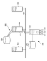
- FIG. 1 shows a schematic diagram of an information system including an ingesting apparatus according to a representative embodiment of the present invention
- FIG. 2 shows a schematic diagram illustrating the information system of FIG. 1, in which the ingesting apparatus evacuates the data to a local as a load on a server to which data is being ingested has increased
- FIG. 3 shows a schematic diagram of the ingesting apparatus according to a representative embodiment
- FIG. 4 shows a block diagram illustrating a hardware configuration of the ingesting apparatus of FIG. 1
- FIG. 5 shows a functional configuration diagram of the ingesting apparatus according to a first embodiment
- FIG. 6 shows a diagram illustrating one example of data of an evacuation header
- FIG. 1 shows a schematic diagram of an information system including an ingesting apparatus according to a representative embodiment of the present invention
- FIG. 2 shows a schematic diagram illustrating the information system of FIG. 1, in which the ingesting apparatus evacuates the data to a local as a load on a server to which data is
- FIG. 7 shows a diagram illustrating one example of a structure of the data of the evacuation header;
- FIG. 8 shows a flow chart illustrating an operation of the ingesting apparatus of FIG. 5;
- FIG. 9A shows a diagram illustrating how the ingesting apparatus of FIG. 5 evacuates a portion of the data to be transmitted to the server on the local;
- FIG. 9B shows a diagram illustrating an operation of the ingesting apparatus of FIG. 5, in which the ingesting apparatus restores the portion of the data that has been evacuated to a storing unit in the server;
- FIG. 10 shows a functional configuration diagram of the ingesting apparatus according to a second embodiment;
- FIG. 11 shows a flow chart illustrating an operation of the ingesting apparatus of FIG. 10;
- FIG. 12 shows a diagram illustrating how the ingesting apparatus of FIG. 10 transmits low resolution data to a server in parallel and stores the low resolution data in a position from which high resolution has been evacuated
- FIG. 13 shows a flow chart illustrating an operation of the ingesting apparatus according to a third embodiment
- FIG. 14 shows a diagram illustrating how the ingesting apparatus of FIG. 13 stores, in the server, low resolution data in a position from which high resolution has been evacuated.
- FIG. 1 and FIG. 2 show a schematic diagram of an information system including an ingesting apparatus according to a representative embodiment of the present invention.
- the information processing system can be configured, for example, as a moving image editing/recording system. Referring to FIG.
- the information processing system is provided with camcorders 121-123 that take images of, for example, an event such as a soccer game or a reporting site and output video data of the images in real time, an ingesting apparatus 100 of a representative embodiment that, when the video data is inputted from the camcorders 121-123, transmits in real time to a server, for example, a server 300 connected via a network and writes into a storage of the server 300 (herein also referred to as "ingest(s)"), and other terminals 200 and 400 that access the server 300 via the network and record and edit the data stored in the server 300.
- a server for example, a server 300 connected via a network and writes into a storage of the server 300 (herein also referred to as "ingest(s)"
- ingest(s) a server 300 connected via a network and writes into a storage of the server 300
- other terminals 200 and 400 that access the server 300 via the network and record and edit the data stored in the server 300.
- the ingesting apparatus 100 that transmits the video data and ingests the data, includes a data retaining unit 361 configured with, for example, a hard disk as a local storage for retaining the video data as needed.
- the server 300 includes a data storing unit 302 configured with, for example, a hard disk as a server storage for storing the video data that has been ingested and a CPU (not shown) that controls the entire operation.
- the video data inputted by the ingesting apparatus 100 from the camcorders 121-123 is, for example, the video data of the images of an event such as a soccer game or a reporting site that are transmitted continuously in real time.
- the ingesting apparatus 100 ingests the video data inputted continuously in real time from the camcorders 121-123 into the server 300, and writes the data into the data storing unit 302 of a server.
- the video data inputted from the camcorders 121-123 is taken as an example of the data that the ingesting apparatus 100 inputs and writes into the data storing unit 302 of the server 300.
- the data that the ingesting apparatus 100 inputs and writes into the data storing unit 302 of the server 300 is not limited to such an example, but may include any type of data such as audio data and program data in addition to video data. Further, video data and audio data that are played by a different playback apparatus that is not shown in the drawing, video data, audio data, program data and the like that are transmitted via a different network may be inputted and written by the ingesting apparatus 100 into the storage of a destination server.
- a writing speed at which the video data is written into the data storing unit 302 of the server 300 can be maintained at a predetermined speed, for example, substantially in real time.
- the video data is smoothly transmitted from the ingesting apparatus 100 to the server 300.
- arrow B in FIG. 2 for example, the traffic suddenly increases or the load on the server 300 increases due to, for example, accesses from terminals 200, 400 to the server 300, and therefore the writing speed at which the server 300 writes the video data into the data storing unit 302 cannot be maintained at the predetermined speed.
- the writing speed at which the data is written into the storage of the server decreases below the transmission speed at which the data is transmitted to the server, failure or such often occurs in a buffer of the ingesting apparatus, thereby ingestion itself is aborted.
- the ingesting apparatus 100 is such that, when it is detected that the server 300 cannot maintain the writing speed at which the video data is being written into the data storing unit 302 at the predetermined speed, for example, substantial real time, the video data that is being continuously inputted from the camcorders 121-123 in substantial real time is retained by the data retaining unit 361, instead of being transmitted to the server 300, as shown by an arrow C. Further, while the writing operation of the data to the storing unit 302 is suspended, a space into which the data retained by the data retaining unit 361 can be written afterwards is secured into the storing unit 302.
- the video data that has been continuously inputted from the camcorders 121-123 and retained by the data retaining unit 361 instead of being stored in the data storing unit 302 of the server 300 while the writing speed of the server 300 is determined to be lower than the predetermined speed is transmitted to the server 300 and written into the space secured in the data storing unit 302 of the server at a predetermined timing, for example, when the writing speed of the server 300 is sufficiently restored or when ingestion is completed.
- the space secured in the data storing unit 302 is a space between a position at which a last block of data, which has been transmitted to the server 300 and stored in the data storing unit 302 of the server 300 immediately before the ingesting apparatus 100 suspends the transmission, is stored, and a position at which a first block of data, which is stored in the data storing unit 302 immediately after the ingesting apparatus 100 has resumed the transmission, is stored.
- the ingesting apparatus 100 carries out ingestion of data to a server with a simple configuration while maintaining reliability and stability, without any access restriction and such, even when the data is continuous and large, and is desired to be processed in real time.
- the data that the ingesting apparatus 100 ingests to the server 300 is described as the video data.
- the present invention is not limited to this, and audio data, program data, signals and such can also be ingested to the server 300 along with or independently from the video data, for example.
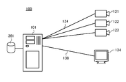
- FIG. 3 shows a schematic diagram of the ingesting apparatus 100 according to the representative embodiment.
- the ingesting apparatus 100 is provided with a main body 101 and a storage 361 connected to the main body 101, and the camcorders 121-123 and a decoder/monitor 134 are connected to the main body 101.
- the ingesting apparatus 100 and each component are connected by, for example, a LAN (Local Area Network) that connects the main body 101 and the storage 361, a coaxial cable 124 that connects the main body 101 and the camcorders 121-123, a cable 138 that connects the main body 101 and the decoder/monitor 134.
- a LAN Local Area Network
- coaxial cable 124 that connects the main body 101 and the camcorders 121-123
- a cable 138 that connects the main body 101 and the decoder/monitor 134.
- the connection form is not limited to this example, and the ingesting apparatus 100 and the components can be connected by a different wired connection (for example, a fibre channel) or by a wireless connection.
- the main body 101 transmits, for example, moving image signals that have been received from the camcorders 121-123 as video data or moving image data to an external terminal such as the server 300.
- the main body 101 also transmits the moving image signals to the decoder/monitor 134.
- the decoder/monitor 134 displays the moving image based on the moving image signals transmitted from the main body 101.
- the "moving image” includes a "still image”.
- FIG. 4 shows a block diagram illustrating a hardware configuration of the ingesting apparatus 100 of the present embodiment.
- the ingesting apparatus 100 is provided with the main body 101 and the storage 361 connected to the main body 101 via a LAN 141, and the camcorders 121-123, splitters 321-323, and the decoder/monitor 134 (FIG. 3) are connected to the ingesting apparatus 100.
- An input unit 315 is for inputting data that is transmitted from the camcorders 121-123.
- the main body 101 is configured by encoders 311-313, a decoder 341 connected to the decoder/monitor 134, a transmitter/receiver unit 350, a CPU (Central Processing Unit) 371, a memory 381, and such, and each of these components are connected by some kind of bus so as to be able to communicate.
- encoders 311-313 a decoder 341 connected to the decoder/monitor 134
- a transmitter/receiver unit 350 a CPU (Central Processing Unit) 371, a memory 381, and such, and each of these components are connected by some kind of bus so as to be able to communicate.
- CPU Central Processing Unit
- the encoders 311-313 each encode moving image signals transmitted from the splitters 321-323, and create encoded moving image data. Further, the encoders 311-313 can read and encode a moving image signal stored in the storage 361. In a first embodiment as later described, the encoders 311-313 are not activated, and the video data inputted from the camcorders 121-123 are transmitted via the transmitter/receiver unit 350 to the external terminal such as the server 300 as a destination of ingestion.
- both or one of uncompressed video data that is inputted from the camcorders 121-123 (also referred to as "high resolution data”) and video data whose amount is reduced by the encoders 311-313 (also referred to as “low resolution data”) are transmitted in some cases.
- the encoders 311-313 can compress the data using any method, as long as the decoder of the server 300 is compatible, such as DV codec for creating intra-frame coded data and MPEG, H.264/AVC system, DVC, DVCPRO, DVCPROHD, JPEG, and JPEG 2000, for creating inter-frame predictive coded data, depending on an actual implementation.
- the present embodiment is described taking an example in which the uncompressed video data is high resolution data and the compressed video data is low resolution data, the present invention is not limited to such an example. What is required is that the data amount of the low resolution data is reduced from the data amount of the high resolution data, and the high resolution data may be compressed data, for example. In this case, it is desirable that both the high resolution data and the low resolution data are encoded using the same encoding method.
- the decoder 341 reads the encoded moving image data from the storage 361, decodes the data, and transmits the decoded moving image signals to a display controller (not shown) and such.
- the transmitter/receiver unit 350 transmits and receives the data, according to a control by the CPU 371, from and to an external terminal such as the server 300 and the terminals 200 and 400, for example. Further, the transmitter/receiver unit 350 is provided with a transmission buffer unit 351 that temporarily stores data immediately before the data is transmitted to other terminals.
- the video data and/or the audio data stored in the buffer unit 351 is sequentially written into the data storing unit 302 of the server 300. Therefore, a space of the transmission buffer unit 351 used for storing the data becomes immediately open, and the transmission buffer unit 351 remains substantially empty.
- the CPU 371 monitors a free space of the transmission buffer unit 351, and determines a writing state of the data written into a storage of the destination terminal.
- the storage 361 is configured by a hard disk, for example, and stores a program that is executed on the CPU 371 and the encoded moving image data transmitted from the encoders 311-313 as needed. Further, the storage 361 can be provided both or either internally or externally to the main body 101.
- the CPU 371 reads the program stored in the memory 381 and carries out various processes. Examples of the program executed by the CPU 371 include applications for editing and playing the moving image data, and an OS (Operating System) for controlling the devices that are connected to the bus.
- OS Operating System
- the memory 381 stores the program that is read from the storage 361. Examples of the program include applications for editing and playing the moving image data, and an OS for controlling the devices that are connected to the bus. Further, the memory 381 can store the moving image signals and the moving image data transmitted from the devices connected to the bus.
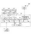
- FIG. 5 shows a functional configuration diagram of the ingesting apparatus according to the first embodiment.
- the ingesting apparatus of the present embodiment carries out functions of each of an input unit 11, a data writing unit 12, a server monitoring unit 15, a data retaining unit 14, and a controlling unit 16, by the components shown in FIG. 4 in cooperate with the program.
- the controlling unit 16 carries out (1) a destination monitoring function for monitoring a writing state of a destination server when transmitting real-time continuous data, (2) a data evacuation and server reservation function for evacuating the data that is continuously inputted to the ingesting apparatus, i.e., a local storage (the data retaining unit 14) instead of transmitting the data to the server when the writing speed of the destination server is determined to be lower than the predetermined speed, and for reserving a space for the evacuated data in the server storage, (3) a transmission resuming function for resuming the transmission of the data that is continuously inputted to the server when the writing speed of the destination server is determined to be restored, and (4) a data restoration function for transmitting the data that has been evacuated to the local storage to the server at a predetermined timing, and for writing the data at a predetermined position in the server.
- a destination monitoring function for monitoring a writing state of a destination server when transmitting real-time continuous data
- a data evacuation and server reservation function for eva
- the input unit 11 can be configured by the input unit 315
- the data writing unit 12 can be configured by the transmitter/receiver unit 350
- the data retaining unit 14 can be configured by the storage 361
- the server monitoring unit 15 can be configured by the transmission buffer unit 351 and the CPU 371 that monitors the amount of the data stored in the transmission buffer unit 351
- the controlling unit 16 can be configured by the CPU 371, for example.
- the storing unit 32 of the server can be configured by, for example, the data storing unit 302 such as a hard disk.
- essential components in the configuration of the ingesting apparatus 100 described with reference to FIG. 3 and FIG. 4 are the CPU 371, the input unit 315, the transmitter/receiver unit 350, the transmission buffer unit 351, and the storage 361.
- the CPU 371 that configures the controlling unit 16 monitors a data writing state of a storage of the server 300 as a destination, i.e., the storing unit 32 (the data storing unit 302) using the server monitoring unit 15.
- the predetermined speed for example, the transmission speed at which the data is transmitted to the server
- the amount of the data stored in the transmission buffer unit 351 increases. If such a situation is maintained, failure or such occurs in the transmission buffer unit 351 and the data that is continuously inputted through the input unit 11 is lost, for example, and thus ingestion itself is aborted.
- the server monitoring unit 15 can monitor the amount of the data stored in the transmission buffer unit 351 to monitor the data writing state of the storing unit 32 of the server 300. With the destination monitoring function, it is possible to monitor the data writing state of the storing unit 32 of the server 300 as the destination, and to take appropriate measures before a failure occurs in the buffer.
- the CPU 371 that configures the controlling unit 16 monitors the writing state of the server 300, which is monitored by the server monitoring unit 15.
- the CPU 371 immediately causes the data writing unit 12 to suspend the transmission of the data continuously inputted through the input unit 11 to the server 300.
- the data continuously inputted through the input unit 11 is retained by the data retaining unit 14, from a block succeeding a last block of the data that has been continuously inputted through the input unit 11, transmitted to the server 300 by the data writing unit 12, and stored in the storing unit 32 of the server 300. With this, it is possible to avoid the failure in the transmission buffer, and to evacuate the data continuously inputted through the input unit 11 to the local storage.
- the ingesting apparatus specifies the last block of the data that has been stored in the storing unit 32 of the server immediately before the transmission is suspended using, for example, a file pointer, and reserves a space so that the data evacuated to the local can be later restored in a storage of the server 300. Further, a header for identification (herein referred to as an "evacuation header") is created at a head of a data block that is first written when the data that has been continuously inputted through the input unit 11 is evacuated to the local, so that the data evacuated to the local can be later restored in the space reserved and secured in the storing unit 32 of the server.
- a header for identification herein referred to as an "evacuation header”
- the evacuation header information necessary for later restoring the evacuated data in the space reserved and secured in the server 300 is recorded. For example, a position of the data block from which the evacuation has started and a size of the evacuated data can be recorded in the evacuation header.
- FIG. 6 One example of the evacuation header is shown in FIG. 6, and one example of a data structure of the evacuation header is shown in FIG. 7.
- a file pointer of the last block of the data that has been written into the storing unit 32 of the server 300 immediately before the transmission is suspended, and information such as the size of the data evacuated to the data retaining unit 14 are recorded.
- the data which the data writing unit 12 suspends the transmission to the server 300 and instead stores in the data retaining unit 14 is provided with the evacuation header thus created at a head portion of the data, and then stored in the data retaining unit 14.
- the ingesting apparatus can notify that the data is temporarily evacuated and not lost due to abortion of ingestion, when a different terminal accesses the server and requests data that is being evacuated to the local storage (the data retaining unit 361), for example.
- the time point at which the transmission buffer unit 351 returns to the substantially empty state can be used as an indication that the writing state of the server 300 has restored the predetermined state.
- the method of monitoring the amount of the space in the transmission buffer unit 351 is described as one example of the method of monitoring the state of writing to the storing unit 32 of the server.
- the present invention is not limited to this example, and any method, that a person having ordinary skill in the art can conceive of, can be used, such as monitoring an error in the storing unit 32.
- the server 300 can store the data that is continuously inputted in the storing unit 32, as the load returning to a normal state, other terminals that access the server 300, i.e., the terminals 200 and 400, can continue a process such as an editing operation in real time, for example.
- the CPU 371 that configures the controlling unit 16 transmits the data, that has been evacuated to the data retaining unit 14 while the server monitoring unit 15 has determined that the writing state of the server 300 is below the predetermined state, to the server at the predetermined timing, and extracts and restores the data in the space that has been reserved and secured in the storing unit 32 of the server 300, that is, the space specified by the evacuation header (see FIG. 9B).
- the predetermined timing can be determined according to an actual implementation, and can be, for example, a time point at which the writing state of the server 300 is determined to be sufficiently restored, a time point at which the writing speed at which the data is written into the storing unit 32 of the server 300 is determined to be restored to a level considerably faster than the transmission speed at which the data is transmitted to the server 300, or a time point at which ingestion is completed.
- the server 300 can appropriately extract the data evacuated to the local storage, i.e., the data retaining unit 14, at a predetermined position in the storing unit 32 configured, for example, by a hard disk of the server 300, without any special configuration. Accordingly, other terminals that access the server 300, for example, the terminals 200 and 400, can properly carry out a process such as the editing operation.
- the server 300 can sequentially read the data from the data retaining unit 14 of the ingesting apparatus.
- the ingesting apparatus can locate a restoring position in the storing unit 32 of the server 300 based on the information of the evacuation header, and write the evacuated data into the free space to be restored.
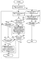
- FIG. 8 shows a flow chart illustrating an operation of the ingesting apparatus of the present embodiment. Referring to FIG. 8 along with FIG. 4, the operation of the ingesting apparatus according to the present embodiment is described. The following process is carried out under the control of the CPU 371 included in the ingesting apparatus.
- Step S21 input of the data commences.
- the input unit 11 commences input of the data that is continuously inputted from the camcorders 121-123, for example.
- Step S22 the data is transmitted to the server.
- the data writing unit 12 transmits the data continuously to the server 300 via the network, and writes the data into the storing unit 32 of the server 300.
- Step S23 it is determined whether or not the writing state of the storing unit 32 of the server 300 is below the predetermined state.
- the server monitoring unit 15 monitors the writing state of the data written into the storing unit 32 of the server 300 based on, for example, the writing speed at which the data is written into the storing unit 32, the amount of the data that has been stored in the transmission buffer unit 351, or the like.
- Step S23 if the writing state of the storing unit 32 of the server 300 is determined to be below the predetermined state, the process proceeds to Step S24.
- Step S23 if the writing state of the storing unit 32 of the server 300 is determined to be at or above the predetermined state, the process proceeds to Step S26.
- Step S24 the data is evacuated to the local storage, that is, the data retaining unit 14, instated of being transmitted to the server 300.
- the space for the data evacuated to the data retaining unit 14 is reserved in the storing unit 32 of the server 300, and the evacuation header is created for the data block that is first written into the data retaining unit 14, so that the data evacuated to the data retaining unit 14 can be later restored in the reserved space.
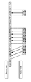
- FIG. 9A shows a diagram illustrating how a portion of continuous data to be ingested to the storing unit 32 of the server 300 is evacuated to the data retaining unit 14.
- the continuous data evacuated to the data retaining unit 14 is such that the last data block and the first data block in the data that has been written into the storing unit 32 of the server 300 can be identified based on the evacuation header described referring to FIG. 6 and FIG. 7. With this, it is possible to identify between which data blocks, of the continuous data ingested in the storing unit 32 of the server 300, the continuous data evacuated to the data retaining unit 14 should be inserted.
- Step S25 it is determined whether or not the writing state of the server is restored.
- the server monitoring unit 15 monitors the writing state of the data written into the storing unit 32 of the server 300 based on, for example, the writing speed at which the data is written into the storing unit 32, the amount of the data that has been stored in the transmission buffer unit 351, or the like.
- Step S25 if the writing state of the storing unit 32 of the server 300 is determined to be restored to the predetermined state, the process returns to Step S22. If the writing state is determined to be not restored, the process returns to Step S24.
- Step S26 it is determined whether or not input of the data has been completed. Specifically, it is determined whether or not input of the data from the camcorders 121-123 to the input unit 11 has been completed. If input of the data is determined to not be complete, the process returns to Step S22. If input of the data is determined to be completed, the process proceeds to Step S27. In Step S27, it is determined whether or not the evacuated data is present in the local storage, that is, the data retaining unit 14. In Step S27, if the evacuated data is determined to be present in the data retaining unit 14, the process proceeds to Step S28. In Step S28, the data evacuated to the local storage, that is, the data retaining unit 14 is written into the secured space in the storing unit 32 of the server, and the ingesting operation is terminated.
- a timing at which the data evacuated to the local data retaining unit 14 is restored in the data storing unit 32 of the server can be, for example, a time point at which the writing state of the storing unit 32 of the server 300 is sufficiently restored, such as when it is determined that the traffic to the server 300 for writing is not busy to an extent that the writing of the evacuated data to the data retaining unit 14 can be carried out in addition to the writing of the data continuously inputted through the input unit 11 to the storing unit 32, or when a predetermined time period lapses after the data input has been completed, and can be determined depending on an actual implementation.
- FIG. 9B shows a diagram illustrating an operation of restoring the data evacuated to the data retaining unit 14 in the storing unit 32 of the server 300.
- the data evacuated to the local data retaining unit 14 is restored in the reserved free space in the storing unit 32 of the server 300.
- the data evacuated to the local data retaining unit 14 is restored, referring to the evacuation header provided for the data, in the space between the position at which the last block of the data in the storing unit 32 that has been transmitted to the server 300 immediately before the data writing unit 12 suspends the transmission and is stored in the storing unit 32 of the server 300, and the position at which the first block of the data stored immediately after the data writing unit has resumed the transmission is stored in the storing unit.
- the ingesting apparatus specifies the restoring position in the storing unit 32 of the server 300 based on the information in the evacuation header, and writes the evacuated data into the free space to be restored.
- the controlling unit 16 immediately causes the data writing unit 12 to suspend the transmission of the data continuously inputted from the input unit 11 to the server. Then, the data continuously inputted through the input unit 11 is retained by the data retaining unit 14, from the block succeeding the last block of the data transmitted to the server by the data writing unit 12 immediately beforehand, and stored in the storing unit of the server.
- the controlling unit 16 immediately causes the data writing unit 12 to resume the transmission of the data continuously inputted through the input unit 11, to the server, when the writing state of the server monitored by the server monitoring unit 15 is determined to be restored to the predetermined state. Further, the controlling unit 16 stores the data that has been continuously inputted through the input unit 11 and retained by the data retaining unit 14 instead of being stored in the storing unit of the server while the server monitoring unit 15 determines that the writing state of the server is below the predetermined state, at the predetermined timing, in the space in the storing unit of the server between the position at which the last block of the data that has been transmitted to the server immediately before the data writing unit 12 suspends the transmission and is stored in the storing unit of the server, and the position at which the first block of the data stored immediately after the data writing unit has resumed the transmission.
- the storage that is normally provided on the local can be used as the data retaining unit for temporarily evacuating, i.e., retaining the data, and therefore, any special hardware for retaining the data is not necessary.
- the free space for restoration is reserved and secured in the storing unit, the evacuated data can be restored in its proper position without fail.
- the data that is evacuated is limited, and the restriction given to the operation can be minimized even when the editing operation is carried out while ingesting the data in real time.
- the server monitoring unit 15 determines that the writing state of the monitored server is below the predetermined state, it is not necessary for a user to consciously carry out any kind of operation.
- there is only a single piece of the data to be edited and the piece of the data is evacuated to the local storage only when the writing state is below the predetermined state. Accordingly, it is possible to realize the present invention with a capacity usually provided for the local storage. Further, as there is no switching of the data, it is possible to suppress functional restrictions as much as possible. Thus, it is possible to carry out ingestion of data to a server with a simple configuration while maintaining reliability and stability, without any access restriction and such, even when the data is continuous and large, and is desired to be processed in real time.
- the data is not transmitted to the server 300 but evacuated to the local data retaining unit 14, when the writing state of the storing unit 32 of the server 300 is determined to be below the predetermined state in Step S23.
- the present invention is not limited to such a configuration. For example, regardless of the writing state of the storing unit 32 of the server 300, it is possible to always continue to transmit data with reduced data amount to the server 300.
- the writing state of the storing unit 32 of the server 300 is determined to be below the predetermined state in Step S23, the data with reduced amount of data can be stored in the storing unit 32 of the server 300 at the same time as the data can be transmitted to and evacuated to the local data retaining unit 14.
- the next embodiment describes this configuration.
- the ingesting apparatus is provided with a data amount reducing unit for reducing an amount of the data to be transmitted, and is different from the ingesting apparatus according to the first embodiment in that the ingesting apparatus transmits the video data in low resolution whose amount of data is reduced to the server along with the video data in high resolution inputted from the camcorders 121-123 and whose amount of data is not reduced or greater than the video data in low resolution.
- FIG. 10 shows a functional configuration diagram of the ingesting apparatus according to the present embodiment.
- the ingesting apparatus according to the present embodiment is provided with a data amount reducing unit 21 that reduces the amount of data, in addition to the configuration of the ingesting apparatus according to the first embodiment.
- the hardware configuration is the same as that of the ingesting apparatus according to the first embodiment other than that the encoders 311-313 configure the data amount reducing unit and the amount of the inputted data is reduced by an operation of the encoders 311-313 in the configuration described with reference to FIG. 4.
- the server 300 is provided with a decoder with an encoding method corresponding to the encoders 311-313, in addition to the CPU that controls the processes.
- the same configurations and steps as in the first embodiment are represented by the same referemce nembers and only major differences from the first embodiment are described with reference to FIG. 10 and FIG. 4.
- the ingesting apparatus carries out, in addition to the functions described in the first embodiment: (1) the destination monitoring function, (2) the data evacuation and server reservation function, (3) the transmission resuming function, and (4) the data restoration function, (5) a low resolution data transmit function for transmitting data with reduced amount of data to the server when transmitting the continuous data. Accordingly, even when the writing state of the server 300 is deteriorated and the continuously inputted data is evacuated to the storage (the data retaining unit 14) of the local, i.e., the ingesting apparatus instead of being transmitted to the server, the low resolution data with reduced amount of data continues to be transmitted to the server 300. Therefore, the server 300 can continue to receive the video data that is taken real time by the camcorders 121-123. Thus, the low resolution data is written into the portion of the storing unit 32 at which the high resolution data cannot be received and ingestion of the data can be continued.
- the data when the data is evacuated, the data is retained in the data retaining unit 14 of the local with the evacuation header described with reference to FIG. 6 and FIG. 7 being provided at the head of the data block. Therefore, when the data is later restored at the predetermined timing, the low resolution data stored in a space in the storing unit 32 between a position at which a last block of the high resolution data that has been transmitted to the server 300 and is stored in the storing unit 32 of the server 300 immediately before the data writing unit 12 suspends the transmission is stored and a position at which a first block of the data that is stored immediately after the data writing unit 12 has resumed the transmission can be easily replaced by the high resolution data evacuated to the data retaining unit 14 of the local in the same manner as described in the previous embodiment.
- FIG. 11 shows a flow chart illustrating an operation of the ingesting apparatus according to the present embodiment.
- the operation of the ingesting apparatus according to the present embodiment is described with reference to FIG. 11 and FIG. 4.
- the following process is carried out under the control of the CPU 371 included in the ingesting apparatus.
- Step S21 input of the continuous data commences.
- the input unit 11 commences input of the continuous data from the camcorders 121-123, for example.
- Step S22 the data is transmitted to the server.
- the data writing unit 12 transmits the data to the server 300 via the network, and has the storing unit 32 of the server 300 store the data.
- Step S41 the amount of the inputted continuous data is reduced.
- the CPU 371 that configures the controlling unit 16 controls the data amount reducing unit 21 to reduce the amount of the data that is continuously inputted through the input unit 11.
- Step S42 the low resolution data, i.e., the data whose amount of data is reduced, is transmitted to the server.
- the data writing unit 12 transmits the low resolution data, i.e., the data whose amount of data is reduced by the data amount reducing unit 21 to the server 300, and has the storing unit 32 of the server 300 store the data.
- Step S43 it is determined whether or not input of the data has been completed.
- Step S41 it is determined whether or not input of the data from the camcorders 121-123 to the input unit 11 has been completed. If input of the data is determined to be not completed, the process returns to Step S41. If input of the data is determined to be completed, the data transmission operation is terminated.
- Step S44 when the high resolution data is evacuated to the data retaining unit 14 instead of being transmitted to the server 300, the controlling unit 16 writes the corresponding low resolution data into the space that the server 300 has secured in the storing unit 32, that is, writes the corresponding low resolution data immediately after the position of the last block of the high resolution data that has been stored.
- the controlling unit 16 writes, into the storing unit 32, the high resolution data that succeeds the low resolution data that has been received immediately before the transmission is resumed with maintaining continuity of the data. Therefore, the low resolution data transmitted to the server 300 in Step S42 may be processed on the server 300, referring to, for example, a time stamp included in the data, synchronized with the high resolution data transmitted in Step S22.
- Step S27 if the evacuated data is determined to be present in the data retaining unit 14, the process proceeds to Step S45.
- Step S45 the data evacuated to the local storage, that is, the data retaining unit 14 is written into the secured space in the storing unit 32 of the server, and the ingesting operation is terminated.
- Step S23, Step S25, and Step S26 are the same as in the steps described in the first embodiment with reference to FIG. 8.
- a timing at which the data evacuated to the local data retaining unit 14 is restored in the data storing unit 32 of the server can be, for example, a time point at which the writing state of the storing unit 32 of the server 300 is sufficiently restored, such as when it is determined that the traffic to the server 300 for writing is not busy to an extent that the writing of the evacuated data to the data retaining unit 14 can be carried out in addition to the writing of the data continuously inputted through the input unit 11 to the storing unit 32, or when a predetermined time period lapses after the data input has been completed, and can be determined depending on an actual implementation.
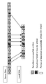
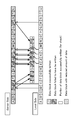
- FIG. 12 shows a diagram illustrating the low resolution data thus stored in the storing unit 32 of the server 300 along with the high resolution data.
- the server 300 while the high resolution data is evacuated to the data retaining unit 14 instead of being transmitted to the server 300, the server 300 writes the low resolution data concurrently transmitted from the ingesting apparatus into the storing unit 32 in place of the high resolution data. In this manner, the server 300 writes the low resolution data into the space in the storing unit 32 immediately after the last block of the high resolution data that has been stored immediately before the evacuation commences. Further, when the ingesting apparatus resumed the transmission of the high resolution data to the server 300, the high resolution data is written into the storing unit 32 with maintaining continuity of the data following the low resolution data that has been written up to then.
- the space in the storing unit 32 in which the low resolution data is written while the high resolution data is evacuated to the data retaining unit 14, is secured as the space in which the evacuated high resolution data is later restored in the storing unit 32.
- the ingesting apparatus according to the present embodiment can use the low resolution data in place of the high resolution data while the high resolution data is evacuated to the local storage (the data retaining unit 14) while maintaining continuity.
- the ingesting apparatus includes, in addition to the features of the ingesting apparatus according to the first embodiment, the data amount reducing unit that reduces the amount of the data, and the data writing unit always transmits the data with reduced amount of data when the data, continuously inputted through the input unit, is transmitted to the server via the network and stored in the storing unit.
- the controlling unit can reduce, with the data amount reducing unit, the amount of the data continuously inputted through the input unit, and thereafter be transmitted to the server by the data writing unit and stored in the storing unit in the server. With this, even when the high resolution data is evacuated to the local, as the server is in a state in which the high resolution data cannot be received, the low resolution data with reduced amount of data is written into the server in place of the high resolution data.
- the low resolution data corresponding to the high resolution data evacuated to the local is instead transmitted to the other terminals.
- the ingesting apparatus always transmits the data with reduced amount of data to the server 300.
- the ingesting apparatus can reduce the amount of the continuously inputted data and transmits the data with reduced data amount to the server 300 in place of the high resolution data, for example, only when the writing state of the server 300 is deteriorated and the continuously inputted data is evacuated to the ingesting apparatus, i.e., the local storage (the data retaining unit 14) without transmitting the continuously inputted data to the server.
- This configuration is described in the following embodiment.
- the ingesting apparatus according to the third embodiment is different from the ingesting apparatus according to the second embodiment in that, the continuous data with reduced amount of data is transmitted to the server 300 only when the continuously inputted data is evacuated to the local storage (the data retaining unit 14).
- the same configurations and steps as in the second embodiment are represented by the same reference numbers and only major differences from the second embodiment are described.
- FIG. 13 shows a flow chart illustrating an operation of the ingesting apparatus according to the present embodiment.
- the hardware configuration is the same as that of the ingesting apparatus according to the first embodiment other than that the encoders 311-313 configure the data amount reducing unit and the amount of the inputted data is reduced by an operation of the encoders 311-313 in the configuration described with reference to FIG. 4.
- the server 300 is provided with a decoder of the type corresponding to the encoders 311-313, in addition to the CPU that controls the processes.
- the operation of the ingesting apparatus according to the present embodiment is described with reference to FIG. 13 and FIG. 4. The following process is carried out under the control of the CPU 371 included in ingesting apparatus.
- the low resolution data is transmitted to the server 300 only when the writing speed of the server decreases.
- Step S21 input of the continuous data commences.
- the input unit 11 commences input of the continuous data from the camcorders 121-123, for example.
- Step S22 the data is transmitted to the server.
- the data writing unit 12 transmits the data to the server 300 via the network, and stores the data in the storing unit 32 of the server 300.
- Step S23 if the writing state of the storing unit 32 of the server 300 is determined to be below the predetermined state, the process proceeds to Step S51.
- Step S51 low resolution data, i.e., the data whose amount of data is reduced is transmitted to the server, and the high resolution data, i.e., data whose amount of data is not reduced or reduced but greater than the low resolution data, is transmitted to the local storage, i.e., the data retaining unit 14.
- the CPU 371 that configures the controlling unit 16 controls the data amount reducing unit 21 to reduce the amount of the data that is continuously inputted through the input unit 11, and controls the data writing unit 12 to transmit the low resolution data with reduced amount of data to the server 300.
- the ingesting apparatus synchronizes the low resolution data with the high resolution data using such a method of referring to a time stamp as described above, so that the server 300 can write the low resolution data from the position immediately after the last block of the high resolution data stored in the storing unit 32 when evacuating the high resolution data to the data retaining unit 14 without transmitting to the server 300, and so that the server 300 can immediately write the high resolution data that succeeds the low resolution data that has been received up to then in the storing unit 32, with maintaining continuity of the data, when the ingesting apparatus resumes the transmission of the high resolution data to the server 300.
- FIG. 14 shows a diagram illustrating how the low resolution data in place of the high resolution data evacuated to the local is stored in the storing unit 32 of the server 300 along with the high resolution data.
- the real time video data is stored while maintaining continuity of the data, so that the server 300 can write the low resolution data from the position immediately after the last block of the high resolution data stored in the storing unit 32 when evacuating the high resolution data to the data retaining unit 14 without transmitting to the server 300, and so that the server 300 can immediately write the high resolution data that succeeds the low resolution data that has been received up to then in the storing unit 32 when the ingesting apparatus resumes the transmission of the high resolution data to the server 300.
- various known methods such as referring to a time stamp can be used.
- the present invention is not limited to such a case.
- various methods can be used and known to a person having ordinary skill in the art, for example, a method of adjusting the amount of the video data by adjusting a quantizing step in quantization.
- the ingesting apparatus includes, in addition to the features of the ingesting apparatus according to the above embodiments, the data amount reducing unit that reduces the amount of the data.
- the controlling unit can, during the time period between the time point at which the server monitoring unit determines the writing state of the server is below the predetermined state and the time point at which the server monitoring unit determines the writing state of the server is restored to the predetermined state, make the amount of the data continuously inputted through the input unit be reduced by the data amount reducing unit, and thereafter be transmitted to the server by the data writing unit and stored in the storing unit in the server.
- the data with reduced amount of data is transmitted to the server in place of the high resolution data. Accordingly, when other terminals access to the server and request the data that has been evacuated to the local, the low resolution data can be transmitted to the other terminals.
- the ingesting apparatus is different from the ingesting apparatus according to the second embodiment in that the data with reduced amount of data is transmitted only when the data is evacuated to the local. Accordingly, processes such as the compression of the data is not always required to be carried out on the ingesting apparatus, and further it is possible to reduce the traffic between the ingesting apparatus and the server.
- the ingesting apparatus can be operated by a data transmission program that causes a commonly used computer provided with a CPU and memory to serve as each of the above described components.
- the data transmission program can be distributed via a communications line, or can be distributed in a form of a program written into a recording medium such as a CD-ROM.
- the present invention is not limited to the embodiments described above. Further, the effects described in the embodiments according to the present invention are mere examples of the preferred effects that can be realized by the present invention, and the effects of the present invention are not limited to those described in the embodiments according to the present invention.
Landscapes
- Engineering & Computer Science (AREA)
- Multimedia (AREA)
- Signal Processing (AREA)
- Computing Systems (AREA)
- Theoretical Computer Science (AREA)
- Information Transfer Between Computers (AREA)
Abstract
Une unité d'écriture de données (12) du dispositif d'ingestion selon l'invention suspend une opération d'écriture de données entrées par l'unité d'entrée (11) dans l'unité de stockage (32), si l'unité de surveillance du serveur (15) détermine que l'état d'écriture se trouve en deçà d'un état prédéterminé. Tandis que l'opération d'écriture est suspendue, les données entrées par l'unité d'entrée (11) sont conservées par l'unité de conservation des données (14), et l'unité d'écriture de données (12) sécurise un espace dans l'unité de stockage (32) pour écrire les données conservées par l'unité de conservation de données (14). L'unité d'écriture de données (12) reprend l'opération d'écriture des données entrées par l'unité d'entrée (11) dans l'unité de stockage (32), si l'unité de surveillance du serveur (15) détermine que l'état d'écriture est restauré à l'état prédéterminé. L'unité d'écriture de données (12) écrit les données conservées par l'unité de conservation des données (14) dans l'espace qui a été sécurisé dans l'unité de stockage (32) à un moment prédéterminé.
Priority Applications (1)
| Application Number | Priority Date | Filing Date | Title |
|---|---|---|---|
| PCT/JP2009/003018 WO2011001465A1 (fr) | 2009-06-30 | 2009-06-30 | Dispositif pour ingérer des données dans un serveur |
Applications Claiming Priority (1)
| Application Number | Priority Date | Filing Date | Title |
|---|---|---|---|
| PCT/JP2009/003018 WO2011001465A1 (fr) | 2009-06-30 | 2009-06-30 | Dispositif pour ingérer des données dans un serveur |
Publications (1)
| Publication Number | Publication Date |
|---|---|
| WO2011001465A1 true WO2011001465A1 (fr) | 2011-01-06 |
Family
ID=41818970
Family Applications (1)
| Application Number | Title | Priority Date | Filing Date |
|---|---|---|---|
| PCT/JP2009/003018 Ceased WO2011001465A1 (fr) | 2009-06-30 | 2009-06-30 | Dispositif pour ingérer des données dans un serveur |
Country Status (1)
| Country | Link |
|---|---|
| WO (1) | WO2011001465A1 (fr) |
Citations (9)
| Publication number | Priority date | Publication date | Assignee | Title |
|---|---|---|---|---|
| US5584006A (en) * | 1989-12-22 | 1996-12-10 | Avid Technology, Inc. | Media storage and retrieval system including determination of media data associated with requests based on source identifiers and ranges within the media data |
| EP0825522A2 (fr) * | 1996-08-23 | 1998-02-25 | Robert Bosch Gmbh | Appareil d'enregistrement de données et méthode d'écriture/lecture sur cet appareil |
| US5742933A (en) * | 1993-06-08 | 1998-04-21 | Hitachi, Ltd. | Rotary memory storage device with cache control method and apparatus |
| JPH10134079A (ja) * | 1996-10-29 | 1998-05-22 | Nippon Steel Corp | 画像データ読み出し方法とその装置およびネットワークシステム |
| JP2002351784A (ja) * | 2001-05-29 | 2002-12-06 | Victor Co Of Japan Ltd | アップロード端末 |
| EP1335544A2 (fr) * | 2002-02-12 | 2003-08-13 | Broadcom Corporation | Traitement de données audio sous forme paquet dans un dispositif de réseau local sans fil |
| WO2004062182A1 (fr) * | 2003-01-07 | 2004-07-22 | Koninklijke Philips Electronics N.V. | Commande du debit binaire joint |
| WO2005104123A2 (fr) * | 2004-04-23 | 2005-11-03 | Koninklijke Philips Electronics N.V. | Enregistrement sans discontinuite d'information en temps reel |
| WO2007007264A2 (fr) * | 2005-07-13 | 2007-01-18 | Koninklijke Philips Electronics N.V. | Procede et appareil permettant d'enregistrer un signal d'entree |
-
2009
- 2009-06-30 WO PCT/JP2009/003018 patent/WO2011001465A1/fr not_active Ceased
Patent Citations (9)
| Publication number | Priority date | Publication date | Assignee | Title |
|---|---|---|---|---|
| US5584006A (en) * | 1989-12-22 | 1996-12-10 | Avid Technology, Inc. | Media storage and retrieval system including determination of media data associated with requests based on source identifiers and ranges within the media data |
| US5742933A (en) * | 1993-06-08 | 1998-04-21 | Hitachi, Ltd. | Rotary memory storage device with cache control method and apparatus |
| EP0825522A2 (fr) * | 1996-08-23 | 1998-02-25 | Robert Bosch Gmbh | Appareil d'enregistrement de données et méthode d'écriture/lecture sur cet appareil |
| JPH10134079A (ja) * | 1996-10-29 | 1998-05-22 | Nippon Steel Corp | 画像データ読み出し方法とその装置およびネットワークシステム |
| JP2002351784A (ja) * | 2001-05-29 | 2002-12-06 | Victor Co Of Japan Ltd | アップロード端末 |
| EP1335544A2 (fr) * | 2002-02-12 | 2003-08-13 | Broadcom Corporation | Traitement de données audio sous forme paquet dans un dispositif de réseau local sans fil |
| WO2004062182A1 (fr) * | 2003-01-07 | 2004-07-22 | Koninklijke Philips Electronics N.V. | Commande du debit binaire joint |
| WO2005104123A2 (fr) * | 2004-04-23 | 2005-11-03 | Koninklijke Philips Electronics N.V. | Enregistrement sans discontinuite d'information en temps reel |
| WO2007007264A2 (fr) * | 2005-07-13 | 2007-01-18 | Koninklijke Philips Electronics N.V. | Procede et appareil permettant d'enregistrer un signal d'entree |
Non-Patent Citations (3)
| Title |
|---|
| "An End-to-End Solution for Managing Television News", INTERNET CITATION, 1 January 2003 (2003-01-01), pages 1 - 8, XP007912362, Retrieved from the Internet <URL:http://www.acehk.com/eng/Manufacturers/dalet/product/news_room_brochu re.pdf> [retrieved on 20100323] * |
| CISCO: "Real-Time Video Services and Distributed Architectures", 31 December 2007 (2007-12-31), pages 1 - 10, XP002575689, Retrieved from the Internet <URL:http://www.cisco.com/en/US/prod/collateral/video/ps7191/ps7127/prod_white_paper0900aecd80653f8c.pdf> [retrieved on 20100323] * |
| RITTER U ET AL: "EFFIZIENZSTEIGERUNG BEI DER NACHRICHTEN-PRODUKTION DURCH VERNETZTE LOESUNGEN", FKT FERNSEH UND KINOTECHNIK, FACHVERLAG SCHIELE & SCHON GMBH., BERLIN, DE, vol. 57, no. 8/09, 1 August 2003 (2003-08-01), pages 406 - 410, XP001220629, ISSN: 1430-9947 * |
Similar Documents
| Publication | Publication Date | Title |
|---|---|---|
| EP1239674B1 (fr) | Enregistrement de données radiodiffusées | |
| JP3633884B2 (ja) | 再生画像伝送装置 | |
| KR20050056208A (ko) | 데이터 관리 방법 | |
| WO2020215453A1 (fr) | Procédé et système d'enregistrement vidéo | |
| CN101860751A (zh) | 动态图像编码装置和动态图像编码方法 | |
| KR20150106351A (ko) | 모션 비디오의 재생을 위한 방법 및 시스템 | |
| US6904089B1 (en) | Encoding device and decoding device | |
| EP0869679A2 (fr) | Codage, décodage et édition | |
| US8411755B2 (en) | Video transmission apparatus and control method for video transmission apparatus | |
| US7613819B2 (en) | Image reproduction apparatus, control method thereof, program and storage medium | |
| JP4440863B2 (ja) | 符号化復号化装置、符号化復号化方法、符号化復号化集積回路、および符号化復号化プログラム | |
| JP2011014948A (ja) | 画像符号化方法及び画像符号化装置、並びにそれらを用いた画像記録再生装置 | |
| US7382971B2 (en) | Image data recording apparatus and method | |
| KR100578438B1 (ko) | 비디오 캡쳐 장치 및 저속 데이타 링크를 통해 고품질의 비디오를 송신하는 방법 | |
| JP3181800B2 (ja) | ビデオサーバ装置 | |
| JP2009100461A (ja) | 映像記録再生装置、映像記録装置、及び映像符号化装置。 | |
| US9225931B2 (en) | Moving image data recording apparatus | |
| JP3279186B2 (ja) | 動画像データの再生制御方式 | |
| WO2011075108A1 (fr) | Procédé de transmission en mode jeu pour une voie à bande passante limitée | |
| JP4350638B2 (ja) | 映像記録装置 | |
| JP2004349743A (ja) | 映像ストリーム切替システム、方法、映像ストリーム切替システムを含む映像監視、映像配信システム | |
| JP4522835B2 (ja) | 画像伝送装置及び画像監視システム | |
| JP4462559B2 (ja) | トリック再生用コンテンツ作成方法および装置、トリック再生用圧縮動画データ送出方法および装置、およびトリック再生用コンテンツ作成用プログラム | |
| JP2008060738A (ja) | 放送素材管理システム、およびその素材管理方法 | |
| JP2002176622A (ja) | 映像信号の記録方法、及び映像信号記録装置 |
Legal Events
| Date | Code | Title | Description |
|---|---|---|---|
| 121 | Ep: the epo has been informed by wipo that ep was designated in this application |
Ref document number: 09787896 Country of ref document: EP Kind code of ref document: A1 |
|
| NENP | Non-entry into the national phase |
Ref country code: DE |
|
| 32PN | Ep: public notification in the ep bulletin as address of the adressee cannot be established |
Free format text: NOTING OF LOSS OF RIGHTS PURSUANT TO RULE 112(1) EPC (EPO FORM 1205A DATED 30/03/2012) |
|
| 122 | Ep: pct application non-entry in european phase |
Ref document number: 09787896 Country of ref document: EP Kind code of ref document: A1 |