WO2011001513A1 - パワーコンディショナー用筐体 - Google Patents
パワーコンディショナー用筐体 Download PDFInfo
- Publication number
- WO2011001513A1 WO2011001513A1 PCT/JP2009/061973 JP2009061973W WO2011001513A1 WO 2011001513 A1 WO2011001513 A1 WO 2011001513A1 JP 2009061973 W JP2009061973 W JP 2009061973W WO 2011001513 A1 WO2011001513 A1 WO 2011001513A1
- Authority
- WO
- WIPO (PCT)
- Prior art keywords
- door
- power conditioner
- circumferential
- pin
- guide
- Prior art date
- Legal status (The legal status is an assumption and is not a legal conclusion. Google has not performed a legal analysis and makes no representation as to the accuracy of the status listed.)
- Ceased
Links
Images


Classifications
-
- H—ELECTRICITY
- H05—ELECTRIC TECHNIQUES NOT OTHERWISE PROVIDED FOR
- H05K—PRINTED CIRCUITS; CASINGS OR CONSTRUCTIONAL DETAILS OF ELECTRIC APPARATUS; MANUFACTURE OF ASSEMBLAGES OF ELECTRICAL COMPONENTS
- H05K5/00—Casings, cabinets or drawers for electric apparatus
- H05K5/02—Details
- H05K5/0217—Mechanical details of casings
- H05K5/0226—Hinges
-
- E—FIXED CONSTRUCTIONS
- E05—LOCKS; KEYS; WINDOW OR DOOR FITTINGS; SAFES
- E05D—HINGES OR SUSPENSION DEVICES FOR DOORS, WINDOWS OR WINGS
- E05D11/00—Additional features or accessories of hinges
- E05D11/06—Devices for limiting the opening movement of hinges
-
- E—FIXED CONSTRUCTIONS
- E05—LOCKS; KEYS; WINDOW OR DOOR FITTINGS; SAFES
- E05D—HINGES OR SUSPENSION DEVICES FOR DOORS, WINDOWS OR WINGS
- E05D3/00—Hinges with pins
- E05D3/02—Hinges with pins with one pin
- E05D3/022—Hinges with pins with one pin allowing an additional lateral movement, e.g. for sealing
-
- E—FIXED CONSTRUCTIONS
- E05—LOCKS; KEYS; WINDOW OR DOOR FITTINGS; SAFES
- E05D—HINGES OR SUSPENSION DEVICES FOR DOORS, WINDOWS OR WINGS
- E05D5/00—Construction of single parts, e.g. the parts for attachment
- E05D5/10—Pins, sockets or sleeves; Removable pins
- E05D5/14—Construction of sockets or sleeves
-
- H—ELECTRICITY
- H05—ELECTRIC TECHNIQUES NOT OTHERWISE PROVIDED FOR
- H05K—PRINTED CIRCUITS; CASINGS OR CONSTRUCTIONAL DETAILS OF ELECTRIC APPARATUS; MANUFACTURE OF ASSEMBLAGES OF ELECTRICAL COMPONENTS
- H05K7/00—Constructional details common to different types of electric apparatus
- H05K7/14—Mounting supporting structure in casing or on frame or rack
- H05K7/1422—Printed circuit boards receptacles, e.g. stacked structures, electronic circuit modules or box like frames
- H05K7/1427—Housings
- H05K7/1432—Housings specially adapted for power drive units or power converters
-
- E—FIXED CONSTRUCTIONS
- E05—LOCKS; KEYS; WINDOW OR DOOR FITTINGS; SAFES
- E05D—HINGES OR SUSPENSION DEVICES FOR DOORS, WINDOWS OR WINGS
- E05D15/00—Suspension arrangements for wings
- E05D15/56—Suspension arrangements for wings with successive different movements
- E05D15/58—Suspension arrangements for wings with successive different movements with both swinging and sliding movements
- E05D15/581—Suspension arrangements for wings with successive different movements with both swinging and sliding movements the swinging axis laying in the sliding direction
-
- E—FIXED CONSTRUCTIONS
- E05—LOCKS; KEYS; WINDOW OR DOOR FITTINGS; SAFES
- E05Y—INDEXING SCHEME ASSOCIATED WITH SUBCLASSES E05D AND E05F, RELATING TO CONSTRUCTION ELEMENTS, ELECTRIC CONTROL, POWER SUPPLY, POWER SIGNAL OR TRANSMISSION, USER INTERFACES, MOUNTING OR COUPLING, DETAILS, ACCESSORIES, AUXILIARY OPERATIONS NOT OTHERWISE PROVIDED FOR, APPLICATION THEREOF
- E05Y2900/00—Application of doors, windows, wings or fittings thereof
- E05Y2900/20—Application of doors, windows, wings or fittings thereof for furniture, e.g. cabinets
- E05Y2900/208—Application of doors, windows, wings or fittings thereof for furniture, e.g. cabinets for metal cabinets
Definitions
- the present invention relates to a casing for a power conditioner that stores equipment of the power conditioner.
- a housing that stores devices includes a housing that is connected to the housing body so that the door can rotate with respect to the housing body. For example, when such a case is installed in a place receiving wind, such as outdoors, the door may sway in a state where the door is closed.
- a technique for suppressing the shaking of the door for example, in Patent Document 1, two folding panels are attached to a door provided as a pair, and recessed portions are respectively formed in lower portions of the back surfaces on the contact side of the two folding panels.
- a convex locking part, and a folding latch that includes a concave latch and a convex latch that are in close contact with each other when the two folding panels are closed are disclosed. ing.
- the case when installed outdoors, the case may receive rain in addition to the wind. Therefore, in the case of a case installed outdoors, it is necessary to suppress water from entering the inside of the case body. Therefore, as a configuration of a case installed outdoors, for example, a rain prevention part that is provided in the case main body so as to protrude to the door side and covers a gap between the door and the case main body is formed.
- the structure which suppresses the approach of water to the inside of a housing body can be considered.
- the door when the door is opened and closed, the door interferes with the rain prevention part. Therefore, conventionally, in the case of a power conditioner case provided outdoors, the door is not configured to rotate around the rotation axis, but is configured so that the door can be completely removed from the main body of the power conditioner. After being stored in the housing body, the door was attached to the housing body with bolts. In the case of such a case, the user needs to remove all the bolts when opening the door and to remove the door from the case main body. Therefore, in the case of such a housing, there is a possibility that the user's trouble is increased when opening and closing the door.
- the present invention has been made in view of the above, and an object of the present invention is to obtain a casing for a power conditioner that can reduce a user's effort required to open and close a door.
- a casing for a power conditioner includes a casing main body that has an opening and accommodates power conditioner devices, and is attached to the casing main body.
- the door that can cover the opening, the shaft provided in one of the housing main body and the door, and the one of the housing main body and the door that is not provided with the shaft.
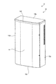
- FIG. 1 is a front view showing a casing for a power conditioner according to Embodiment 1 when a door is closed.
- FIG. FIG. 2 is a front view showing the power conditioner casing according to Embodiment 1 when the door is open.
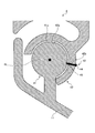
- FIG. 3 is a cross-sectional view showing the hinge portion according to the first embodiment when the door is open, cut along a virtual plane orthogonal to the rotation axis.
- FIG. 4 is a cross-sectional view showing the hinge portion according to the first embodiment when the door is closed, cut along a virtual plane orthogonal to the rotation axis.
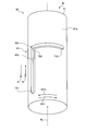
- FIG. 5 is an enlarged perspective view schematically showing the guide mechanism of the first embodiment.
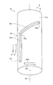
- FIG. 6 is an enlarged perspective view schematically showing the guide mechanism of the second embodiment.
- FIG. 7 is an enlarged perspective view schematically showing the guide mechanism of the third embodiment.
- FIG. 8 is a cross-sectional view of the hinge portion according to the fourth embodiment cut along a virtual plane perpendicular to the rotation axis.
- FIG. 9 is a perspective view schematically showing an enlarged guide groove of the fourth embodiment.
- FIG. 10 is an enlarged perspective view schematically showing the guide mechanism of the fifth embodiment.
- FIG. 11 is an enlarged perspective view schematically illustrating the guide mechanism of the sixth embodiment.
- FIG. 1 is a front view showing a casing for a power conditioner according to Embodiment 1 when a door is closed.
- FIG. FIG. 2 is a front view showing the power conditioner casing according to Embodiment 1 when the door is open.
- the power conditioner casing 1 according to the first embodiment includes a casing body 10 and a door 11 as shown in FIGS. 1 and 2.
- the housing body 10 includes a back plate 10a, a top plate 10b, a bottom plate 10c, and two side plates 10d.
- the top plate 10b, the bottom plate 10c, and the two side plates 10d are provided, for example, vertically on the same side surface of the back plate 10a.
- the top plate 10b and the bottom plate 10c are provided to face each other.
- the two side plates 10d are provided to face each other.
- the housing body 10 is formed in a box shape having an opening 10e by a back plate 10a, a top plate 10b, a bottom plate 10c, and two side plates 10d.
- the opening 10e includes an end portion of the top plate 10b opposite to the back plate 10a, an end portion of the bottom plate 10c opposite to the back plate 10a, and an end of the side plate 10d. It is an opening enclosed by the edge part on the opposite side to the backplate 10a among parts.
- power conditioner devices are stored in the box-shaped casing body 10.
- the door 11 is connected to one of the two side plates 10d so as to be rotatable about the rotation axis RL.
- the rotation axis RL is orthogonal to the top plate 10b and the bottom plate 10c.
- the door 11 is rotated about the rotation axis RL, so that the opening 10e is covered by the door 11 as shown in FIG. 1, or the opening 10e is opened as shown in FIG. 10e is released.
- the state in which the opening 10e is covered by the door 11 is referred to as a state where the door is closed, and the state in which the opening 10e is open is referred to as a state in which the door is open.
- a configuration of a connecting portion between the door 11 and the housing body 10, that is, a so-called hinge portion will be described.
- FIG. 3 is a cross-sectional view showing the hinge portion according to the first embodiment when the door is open, cut along a virtual plane perpendicular to the rotation axis.
- FIG. 4 is a cross-sectional view showing the hinge portion according to the first embodiment when the door is closed, cut along a virtual plane orthogonal to the rotation axis.
- the hinge portion of the power conditioner housing 1 includes a shaft body 13 and a bearing 14.
- the shaft body 13 has a circular cross section cut by a virtual plane orthogonal to the rotation axis RL.
- a cross section cut by a virtual plane orthogonal to the rotation axis RL is simply referred to as a cross section.
- the rotation axis RL passes through the center of the cross section of the shaft body 13.
- the shaft body 13 is provided on the door 11.
- the bearing 14 is formed in a shape that covers at least a part of the outer peripheral surface 13 a of the shaft body 13.
- the bearing 14 is formed in a shape in which a part of the cylindrical shape is missing while avoiding a connecting portion between the shaft body 13 and the door 11.
- the bearing 14 has a substantially C-shaped cross section.
- the bearing 14 is provided in the housing body 10 in the present embodiment. *
- the shaft 13 is inserted inside the bearing 14.
- the inner side is a space surrounded by a C-shaped portion of the bearing 14 having a substantially C-shaped cross section.
- the shaft body 13 is supported by the bearing 14 in the power conditioner casing 1 so that the shaft body 13 can move relative to the bearing 14 in the direction of the rotation axis RL.
- the casing 1 for the power conditioner can be supported by the hinge portion so that the door 11 can move in the direction of the rotation axis RL with respect to the casing body 10.
- the hinge portion is not limited to a configuration in which the shaft body 13 is provided on the door 11 and the bearing 14 is provided on the housing body 10.
- the shaft body 13 may be provided in the housing body 10, and the bearing 14 may be provided in the door 11.
- the hinge portion is formed with a relief portion 14 b in the bearing 14 or the housing body 10.
- the escape portion 14b is a portion where a part of the door 11 is taken in and out.
- the case 1 for the power conditioner is designed on the assumption that it is provided outdoors. Therefore, as shown in FIGS. 1 and 2, the power conditioner casing 1 has a rain protection portion 10 f at the end of the top plate 10 b opposite to the back plate 10 a.
- the rain prevention part 10f protrudes toward the bottom plate 10c side.
- the rain protection part 10f is formed, for example, by bending the top board 10b.
- the shaft body 13 is supported by the bearing 14 in the casing 1 for the power conditioner so that the shaft body 13 can move in the direction of the rotation axis RL relative to the bearing 14.
- casing 1 for power conditioners can move the door 11 to the rotation-axis RL direction so that when the door 11 is opened, the door 11 and the rain prevention part 10f do not interfere with each other.
- a direction in which the door 11 is separated from the rain protection portion 10 f in the rotation axis RL direction is defined as a predetermined direction A.
- the door 11 is rotated about the rotation axis RL, and the door 11 is opened.
- the casing 1 for the power conditioner has a guide mechanism 15 for restricting the movement of the door 11. The configuration of the guide mechanism 15 will be described below.
- FIG. 5 is an enlarged perspective view schematically showing the guide mechanism of the first embodiment.
- At least one guide mechanism 15 is provided at the hinge portion between the door 11 and the housing body 10.
- two guide mechanisms 15 are provided at the hinge portion between the door 11 and the housing body 10 as shown in FIG.
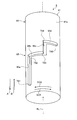
- the guide mechanism 15 includes a pin 16 and a guide hole 17 serving as a guide unit with which the pin 16 engages.
- the pin 16 is provided on the shaft body 13 in the present embodiment.
- the pin 16 is a protrusion that protrudes radially outward of the shaft body 13 from the outer peripheral surface 13 a of the shaft body 13 toward the bearing 14.
- the pin 16 is, for example, a bolt.
- a male screw portion is not formed in a portion that engages with the guide hole 17. That is, the pin 16 has a male screw portion formed only at the tip portion. Thereby, the fall of the durability of the guide hole 17 resulting from the male screw part of the pin 16 engaging with the guide hole 17 can be suppressed.
- the guide mechanism 15 has the female screw hole in which a female screw hole is formed in the outer peripheral surface 13 a of the shaft body 13 and the male screw portion formed in the pin 16 is formed in the outer peripheral surface 13 a of the shaft body 13.
- the pin 16 is attached to the shaft body 13 by being screwed into the hole.
- the guide hole 17 is formed in the bearing 14.
- the guide hole 17 is a hole that penetrates the bearing 14 in the radial direction of the bearing 14.
- the guide hole 17 includes an axial guide hole 17a as an axial portion of the guide means and a circumferential guide hole 17b as a circumferential portion of the guide means.
- the axial guide hole 17 a is a part of the guide hole 17 parallel to the rotation axis RL.
- the circumferential guide hole 17 b is a part formed in the circumferential direction of the bearing 14 in the guide hole 17.
- the circumferential direction here includes a direction inclined to the axial guide hole 17a in addition to a direction orthogonal to the axial guide hole 17a.
- the guide hole 17 intersects with the axial guide hole 17a and the circumferential guide hole 17b communicating with each other.
- the axial guide hole 17a and the circumferential guide hole 17b are orthogonal to each other.
- the guide hole 17 is formed in a substantially L shape.
- the shaft body 13 rotates about the rotation axis RL.
- the pin 16 attached to the shaft body 13 also rotates around the rotation axis RL.
- a direction in which the door 11 rotates when the door 11 is opened is referred to as a door rotation direction S01.
- the pin 16 is connected to the shaft body 13 and the pin 16 also rotates together with the door 11. Therefore, the door rotation direction S01 coincides with the direction in which the pin 16 tries to move when the door 11 is opened.
- the circumferential guide hole 17b is formed from the axial guide hole 17a toward the door rotation direction S01.
- the shaft body 13 is first attached to the bearing 14 in a state where the pin 16 is not attached to the shaft body 13.
- the shaft body 13 is positioned inside the bearing 14 so that the female screw hole formed in the outer peripheral surface 13a of the shaft body 13 and the guide hole 17 face each other.
- the pin 16 is screwed into the female screw hole formed in the outer peripheral surface 13a of the shaft body 13 through the guide hole 17 toward the rotation axis RL. In this manner, the guide mechanism 15 is assembled to the power conditioner casing 1.
- an end portion of the guide hole 17 where the axial guide hole 17a is closed is referred to as a first end portion T11.
- a portion of the guide hole 17 where the axial guide hole 17a and the circumferential guide hole 17b communicate with each other is defined as an intersection T12.
- occludes among the parts of the guide hole 17 be 2nd edge part T13.
- the first end T11 is formed closer to the rain shielding part 10f shown in FIG. 1 than the intersection T12.
- the second end T13 is formed away from the intersection T12 in the door rotation direction S01.
- the pin 16 engages with the guide hole 17 at the first end T11.
- the pin 16 is engaged with the axial guide hole 17a in the casing 1 for the power conditioner. Therefore, in the power conditioner casing 1, the movement of the pin 16 in the door rotation direction S01 is restricted by the axial guide hole 17a. Therefore, in the case 1 for the power conditioner, the door 11 does not rotate about the rotation axis RL. Thereby, the casing 1 for a power conditioner can suppress interference between the door 11 and the rain prevention part 10f shown in FIG.
- the user When opening the door 11, the user applies a force in a predetermined direction A to the door 11 in the direction of the rotation axis RL. At this time, the pin 16 moves toward the circumferential guide hole 17b along the axial guide hole 17a. That is, the pin 16 moves in the predetermined direction A from the first end T11 toward the intersection T12.
- the pin 16 In the case 1 for the power conditioner, when the pin 16 reaches the intersection T12, the pin 16 engages with the circumferential guide hole 17b. Then, the pin 16 cannot move in the predetermined direction A any more. Thereby, the casing 1 for the power conditioner can limit the amount of movement of the door 11 in the predetermined direction A.
- the user rotates the door 11 in the door rotation direction S01 about the rotation axis RL.
- the pin 16 moves in the door rotation direction S01 from the intersection T12 toward the second end T13 along the circumferential guide hole 17b.
- the casing 1 for the power conditioner can limit the rotation amount of the door 11 in the door rotation direction S01.
- the power conditioner casing 1 faces the axial guide hole 17a and the door rotation direction S01, which is the direction in which the pin 16 tends to move relative to the guide hole 17 when the door 11 is opened. And a circumferential guide hole 17b formed.
- the axial guide hole 17 a guides the shaft body 13 so that the door 11 is moved in the predetermined direction A.
- the casing 1 for the power conditioner allows the circumferential guide hole 17b to move in the opening direction S01 of the pin 16.
- the circumferential guide hole 17 b can guide the shaft body 13 so as to rotate the door 11 in the door rotation direction S ⁇ b> 01.
- the casing 1 for a power conditioner can suppress interference between the door 11 and the rain prevention part 10f shown in FIG.
- the casing 1 for the power conditioner can suppress a possibility that the user's trouble increases when the door 11 is opened and closed.
- the power conditioner casing 1 is provided with the guide mechanism 15 so that the amount of movement of the door 11 in the predetermined direction A can be regulated.
- the casing 1 for the power conditioner suppresses the possibility that the shaft body 13 moves excessively in the direction of the rotation axis RL, for example, the door 11 collides with the ground or the shaft body 13 comes off from the bearing 14. it can.
- the power conditioner casing 1 includes the guide mechanism 15, thereby restricting the amount of rotation of the door 11 in the door rotation direction S01. Thereby, the casing 1 for the power conditioner can set the maximum opening of the door 11.
- FIG. FIG. 6 is an enlarged perspective view schematically showing the guide mechanism of the second embodiment.
- the guide mechanism 23 of the power conditioner casing 2 according to the second embodiment is different from the guide mechanism 15 of the power conditioner casing 1 according to the first embodiment in the shape of the guide holes.
- the guide mechanism 23 includes a pin 16 and a guide hole 25 serving as a guide unit with which the pin 16 is engaged.
- the guide hole 25 is formed in the bearing 22.
- the guide hole 25 is a hole that penetrates the bearing 22 in the radial direction of the bearing 22.
- the guide hole 25 includes an axial guide hole 25a as an axial portion of the guide means and a circumferential guide hole 25b as a circumferential portion of the guide means.
- the axial guide hole 25a is formed in parallel to the rotation axis RL.
- the circumferential guide hole 25 b is formed toward the circumferential direction of the bearing 22. Further, the circumferential guide hole 25b is formed to be inclined with respect to the axial guide hole 25a.
- the circumferential guide hole 25b is formed from the axial guide hole 25a toward an intermediate direction between the door rotation direction S01 and the predetermined direction A.
- the guide hole 25 intersects with an axial guide hole 25a and a circumferential guide hole 25b communicating with each other.
- a portion of the guide hole 25 an end portion where the axial guide hole 25a is closed is referred to as a first end portion T21.
- a portion of the guide hole 25 where the axial guide hole 25a and the circumferential guide hole 25b communicate with each other is defined as an intersection T22.
- occludes among the parts of the guide hole 25 be 2nd edge part T23.
- the first end T21 is formed closer to the rain shielding part 10f shown in FIG. 1 than the intersection T22.
- the second end portion T23 is formed farther in the door rotation direction S01 than the intersection portion T22, and is formed farther from the rain protection portion 10f than the intersection portion T22.
- the pin 16 engages with the guide hole 25 at the first end T21.
- the pin 16 of the power conditioner casing 2 is engaged with the axial guide hole 25a. Therefore, in the power conditioner casing 2, the movement of the pin 16 in the door rotation direction S01 is restricted by the axial guide hole 25a. Therefore, in the case 2 for the power conditioner, the door 11 does not rotate around the rotation axis RL.
- casing 2 for power conditioners can suppress interference with the door 11 shown in FIG. 1, and the rain prevention part 10f.
- the user When opening the door 11, the user applies a force in a predetermined direction A to the door 11 in the direction of the rotation axis RL. At this time, the pin 16 moves in the predetermined direction A from the first end T21 toward the intersection T22 along the axial guide hole 25a.
- the pin 16 engages with the circumferential guide hole 25b. Then, the pin 16 is further restricted from moving in the predetermined direction A.
- casing 2 for power conditioners can restrict
- the power conditioner casing 2 has a bottom plate 10c shown in FIG.
- the predetermined direction A is a direction toward the lower side in the vertical direction
- the second end T23 is disposed on the lower side in the vertical direction than the intersection T22. Therefore, the guide mechanism 23 tends to move while being guided by the circumferential guide hole 25b toward the second end T23 by the dead weight of the door 11. As a result, the power conditioner casing 2 can reduce the force applied to the door 11 by the user in order to rotate the door 11 in the door rotation direction S01.
- the intersecting portion T22 is on the upper side in the vertical direction from the second end portion T23. Therefore, in the case 2 for the power conditioner, when the pin 16 reaches the second end T23, the pin 16 is pressed against the second end T23 by the dead weight of the door 11. Thereby, the guide mechanism 23 can regulate the rotation of the door 11 around the rotation axis RL. Therefore, for example, when the user (operator) opens the door 11 to perform maintenance / inspection of the power conditioner, the guide mechanism 23 can suppress the possibility that the door 11 is unintentionally closed.
- FIG. 7 is an enlarged perspective view schematically showing the guide mechanism of the third embodiment.
- the guide mechanism 33 of the power conditioner casing 3 according to the third embodiment is such that the shape of the guide hole is the guide mechanism 15 of the power conditioner casing 1 according to the first embodiment or the power conditioner according to the second embodiment. Different from the guide mechanism 23 of the housing 2.
- the guide mechanism 33 includes a pin 16 and a guide hole 35 serving as a guide unit with which the pin 16 engages.
- the guide hole 35 is formed in the bearing 32.
- the guide hole 35 is a hole that penetrates the bearing 32 in the radial direction of the bearing 32.
- the guide hole 35 includes a first axial guide hole 35a as a first axial portion of the guide means, a first circumferential guide hole 35b as a first circumferential portion of the guide means, and a second axial direction of the guide means. It includes a second axial guide hole 35c as a portion and a second circumferential guide hole 35d as a second circumferential portion of the guide means.
- the first axial guide hole 35a and the second axial guide hole 35c are formed in parallel to the rotation axis RL.
- the first axial guide hole 35 a and the second axial guide hole 35 c are formed at different positions in the circumferential direction of the bearing 32. In the present embodiment, the first axial guide hole 35a and the second axial guide hole 35c are formed in parallel to each other.
- the first circumferential guide hole 35 b and the second circumferential guide hole 35 d are formed toward the circumferential direction of the bearing 32.
- the first circumferential guide hole 35b and the second circumferential guide hole 35d are formed at different positions in the rotation axis RL direction of the bearing 32.
- the first circumferential guide hole 35b and the second circumferential guide hole 35d are formed in parallel to each other.
- the first circumferential guide hole 35b and the second circumferential guide hole 35d are formed orthogonal to the first axial guide hole 35a and the second axial guide hole 35c.
- one of the first circumferential guide holes 35b communicates with the first axial guide hole 35a, and the other of the first circumferential guide holes 35b communicates with the second axial guide hole 35c. Further, in the guide hole 35, one of the second circumferential guide holes 35d communicates with the second axial guide hole 35c, and the other of the second circumferential guide holes 35d is closed.
- first end portion T31 an end portion where the first axial guide hole 35a is closed is referred to as a first end portion T31.
- the part which the 1st axial direction guide hole 35a and the 1st circumferential direction guide hole 35b mutually connect among the parts of the guide hole 35 is set as 1st crossing part T32.
- a portion where the first circumferential guide hole 35b and the second axial guide hole 35c communicate with each other is defined as a second intersecting portion T33.
- a portion of the guide hole 35 where the second axial guide hole 35c and the second circumferential guide hole 35d communicate with each other is defined as a third intersection T34. Moreover, let the edge part which 35 d of 2nd circumferential direction guide holes close among the parts of the guide hole 35 be 2nd edge part T35.
- 1st edge part T31 is formed in the rain prevention part 10f side shown in FIG. 1 rather than the 1st cross
- the second intersection T33 is formed farther in the door rotation direction S01 than the first intersection T32.
- the third intersection T34 is formed farther from the rain shielding part 10f than the second intersection T33.
- the second end portion T35 is formed away from the third intersection portion T34 in the door rotation direction S01.
- the pin 16 engages with the first axial guide hole 35a at the first end T31.
- the pin 16 of the power conditioner casing 3 is engaged with the first axial guide hole 35a. Therefore, in the power conditioner casing 3, the movement of the pin 16 in the door rotation direction S01 is restricted by the first axial guide hole 35a. Therefore, the door 11 does not rotate around the rotation axis RL in the case 3 for the power conditioner.
- casing 3 for power conditioners can suppress interference with the door 11 shown in FIG. 1, and the rain prevention part 10f.
- the user When opening the door 11, the user applies a force in a predetermined direction A to the door 11 in the direction of the rotation axis RL. At this time, the pin 16 moves from the first end T31 toward the first intersection T32 along the first axial guide hole 35a. In the case 3 for the power conditioner, when the pin 16 reaches the first intersection T32, the pin 16 engages with the first circumferential guide hole 35b. Next, the user rotates the door 11 in the door rotation direction S01 about the rotation axis RL. As a result, the pin 16 moves from the first intersection T32 toward the second intersection T33 along the first circumferential guide hole 35b. At this time, since the door 11 is moved in the predetermined direction A, the door 11 does not interfere with the rain avoiding portion 10f as shown in FIG.
- the guide mechanism 33 causes the pin 16 to engage with the second axial guide hole 35c. Then, the pin 16 moves from the second intersection T33 toward the third intersection T34 along the second axial guide hole 35c. At this time, in the guide mechanism 33, the pin 16 moves in the predetermined direction A by the dead weight of the door 11.
- the pin 16 reaches the third intersection T34, the user rotates the door 11 in the door rotation direction S01 around the rotation axis RL. At this time, the pin 16 moves from the third intersection T34 toward the second end T35 along the second circumferential guide hole 35d. Thereby, the door 11 rotates in the door rotation direction S01 about the rotation axis RL.
- the power conditioner housing 3 when the pin 16 is engaged with the second circumferential guide hole 35d, that is, when the door 11 is opened, the power conditioner housing 3 has the second end T35 and the second end T35.
- the movement of the pin 16 in the circumferential direction is restricted by the three intersecting portion T34.
- the guide mechanism 33 can regulate the rotation about the rotation axis RL of the door 11 between the third intersection T34 and the second end T35. Therefore, for example, when the user (operator) opens the door 11 and performs maintenance / inspection of the power conditioner, the guide mechanism 33 can suppress the possibility that the door 11 is unintentionally closed.
- FIG. FIG. 8 is a cross-sectional view of the hinge portion according to the fourth embodiment cut along a virtual plane perpendicular to the rotation axis.
- the guide mechanism 43 of the power conditioner casing 4 according to the fourth embodiment is characterized in that a guide means is formed on the shaft body 41 and a pin 44 is provided on the bearing 42. As shown in FIG. 8, the guide mechanism 43 includes a pin 44 and a guide groove 45 as guide means with which the pin 44 engages.
- the pin 44 is provided on the bearing 42.
- the pin 44 is a protrusion that protrudes from the inner peripheral surface 42 a of the bearing 42 toward the shaft body 41.
- the pin 44 is, for example, a bolt.
- the male part of the pin 44 is not formed in the part engaged with the guide groove 45.
- the pin 44 is formed with a male screw portion only at the root portion.
- the guide mechanism 43 has a mounting hole 42 b formed in the bearing 42.
- the mounting hole 42b is a hole that penetrates the bearing 42 in the radial direction.
- a female screw is formed in the mounting hole 42b.
- the male screw portion formed on the pin 44 is screwed into the mounting hole 42 b formed in the bearing 42, so that the tip of the pin 44 projects from the inner peripheral surface 42 a of the bearing 42 toward the shaft body 41. To be attached.
- FIG. 9 is a perspective view schematically showing an enlarged guide groove of the fourth embodiment.
- the guide groove 45 is formed in the shaft body 41.
- the guide groove 45 is a groove that is recessed from the outer peripheral surface 41a of the shaft body 41 toward the rotation axis RL.
- the guide groove 45 includes an axial guide groove 45a as an axial portion of the guide means and a circumferential guide groove 45b as a circumferential portion of the guide means.
- the axial guide groove 45a is formed in parallel with the rotation axis RL.
- the circumferential guide groove 45 b is formed toward the circumferential direction of the bearing 42.
- the guide groove 45 intersects with the axial guide groove 45a and the circumferential guide groove 45b communicating with each other.
- the axial guide groove 45a and the circumferential guide groove 45b are orthogonal to each other.
- the shaft body 41 rotates about the rotation axis RL. Accordingly, in the guide mechanism 43, the guide groove 45 formed in the shaft body 41 rotates about the rotation axis RL.
- the guide mechanism 43 does not rotate the pin 44 attached to the bearing 42.
- the pin 44 moves relative to the guide groove 45 when the guide groove 45 moves relative to the pin 44.
- the movement of the guide groove 45 to change the position with respect to the pin 44 is expressed as “the pin 44 moves relative to the guide groove 45”.
- a direction in which the pin 44 tends to move relative to the guide groove 45 when the door 11 is opened is defined as a pin rotation direction S02.
- the circumferential guide groove 45b is formed from the axial guide groove 45a toward the pin rotation direction S02.
- the pin rotation direction S02 is opposite to the door rotation direction S01 shown in FIGS.
- the shaft body 41 is first attached to the bearing 42 in a state where the pin 44 is not attached to the bearing 42.
- the casing 4 for the power conditioner is disposed inside the bearing 42 so that the guide groove 45 formed on the outer peripheral surface 41a of the shaft body 41 and the mounting hole 42b formed on the bearing 42 face each other.
- the shaft body 41 is positioned.
- the pin 44 is screwed into the mounting hole 42 b toward the rotation axis RL until the tip of the pin 44 engages with the guide groove 45. In this way, the guide mechanism 43 is assembled to the power conditioner casing 4.
- first end portion T41 an end portion where the axial guide groove 45a is closed is referred to as a first end portion T41.
- a portion where the axial guide groove 45a and the circumferential guide groove 45b communicate with each other is defined as an intersection T42.
- occludes among the parts of the guide groove 45 be 2nd edge part T43.
- the first end portion T41 is formed farther from the rain shielding portion 10f shown in FIG. 1 than the intersecting portion T42.
- the second end portion T43 is formed away from the intersecting portion T42 in the pin rotation direction S02. *
- the pin 44 engages with the guide groove 45 at the first end T41.
- the pin 44 of the power conditioner casing 4 is engaged with the axial guide groove 45a. Therefore, in the power conditioner casing 4, the movement of the pin 44 in the pin rotation direction S02 is restricted by the axial guide groove 45a. Therefore, in the power conditioner casing 4, the door 11 does not rotate about the rotation axis RL. Thereby, the casing 4 for the power conditioner can suppress interference between the door 11 and the rain prevention part 10f shown in FIG.
- the user When opening the door 11, the user applies a force in a predetermined direction A to the door 11 in the direction of the rotation axis RL. At this time, the pin 44 moves relative to the guide groove 45 in the predetermined direction B from the first end T41 toward the intersection T42 along the axial guide groove 45a.
- the predetermined direction B is opposite to the predetermined direction A.
- the casing 4 for the power conditioner can limit the amount of movement of the door 11 in the predetermined direction A.
- the user rotates the door 11 in the door rotation direction S01 about the rotation axis RL.
- the pin 44 moves relative to the guide groove 45 from the intersecting portion T42 toward the second end portion T43 along the circumferential guide groove 45b.
- the casing 4 for the power conditioner can limit the amount of rotation of the door 11 in the door rotation direction S01.
- the power conditioner housing 4 has the axial guide groove 45a and the pin rotation direction that is the direction in which the pin 44 tends to move relative to the guide groove 45 when the door 11 is opened. And a circumferential guide groove 45b formed toward S02. Thereby, the casing 4 for the power conditioner first guides the shaft body 41 so as to move the door 11 toward the predetermined direction A.
- the casing 4 for the power conditioner allows the circumferential guide groove 45b to move in the opening direction S02 of the pin 44. That is, the casing 4 for the power conditioner can guide the shaft body 41 so as to rotate the door 11 in the door rotation direction S01. Therefore, the casing 4 for the power conditioner can suppress interference between the door 11 and the rain prevention part 10f shown in FIG. As described above, even when the power conditioner housing includes the rain protection portion 10f shown in FIGS. 1 and 2, the user can easily remove the door 11 without having to completely remove the door 11 from the housing body 10. Can be opened and closed. Therefore, the casing 5 for the power conditioner can suppress the possibility that the user's trouble increases when the door 11 is opened and closed.
- the casing 4 for the power conditioner can regulate the amount of movement of the door 11 in the predetermined direction A by including the guide mechanism 43.
- the casing 4 for the power conditioner suppresses the possibility that the shaft body 41 moves excessively in the direction of the rotation axis RL, for example, the door 11 collides with the ground or the shaft body 41 falls out of the bearing 42. it can.
- the casing 4 for the power conditioner includes the guide mechanism 43 so that the rotation amount of the door 11 in the door rotation direction S01 can be regulated. Thereby, the casing 4 for power conditioners can set the maximum opening degree of the door 11.
- FIG. FIG. 10 is an enlarged perspective view schematically showing the guide mechanism of the fifth embodiment.
- the guide mechanism 53 of the power conditioner casing 5 according to the fifth embodiment is different from the guide mechanism 43 of the power conditioner casing 4 according to the fourth embodiment in the shape of the guide groove.
- the guide mechanism 53 includes a pin 44 and a guide groove 55 serving as a guide unit with which the pin 44 engages.
- the guide groove 55 is formed in the shaft body 51.
- the guide groove 55 is a groove that is recessed from the outer peripheral surface 51 a of the shaft body 51 toward the rotation axis RL.
- the guide groove 55 includes an axial guide groove 55a as an axial portion of the guide means and a circumferential guide groove 55b as a circumferential portion of the guide means.
- the axial guide groove 55a is formed in parallel to the rotation axis RL.
- the circumferential guide groove 55 b is formed toward the circumferential direction of the bearing 42.
- the circumferential guide groove 55b is formed to be inclined with respect to the axial guide groove 55a.
- the guide groove 55 intersects with the axial guide groove 55a and the circumferential guide groove 55b communicating with each other.
- the circumferential guide groove 55b is formed from the axial guide groove 55a toward an intermediate direction between the pin rotation direction S02 and the predetermined direction B.
- an end portion where the axial guide groove 55a is closed is referred to as a first end portion T51.
- a portion of the guide groove 55 where the axial guide groove 55a and the circumferential guide groove 55b communicate with each other is defined as an intersection T52.
- occludes among the parts of the guide groove 55 be 2nd edge part T53.
- the first end portion T51 is formed farther from the rain shielding portion 10f shown in FIG. 1 than the intersection portion T52.
- the second end portion T53 is formed farther in the pin rotation direction S02 than the intersecting portion T52, and is formed closer to the rain protection portion 10f than the intersecting portion T52.
- the pin 44 engages with the guide groove 55 at the first end T51.
- the pin 44 of the power conditioner casing 5 is engaged with the axial guide groove 55a. Therefore, in the power conditioner casing 5, the movement of the pin 44 in the pin rotation direction S02 is restricted by the axial guide groove 55a. Accordingly, in the power conditioner casing 5, the door 11 does not rotate about the rotation axis RL. Thereby, the casing 5 for the power conditioner can suppress interference between the door 11 and the rain prevention part 10f shown in FIG.
- the user When opening the door 11, the user applies a force in a predetermined direction A to the door 11 in the direction of the rotation axis RL. At this time, the pin 44 moves relative to the guide groove 55 from the first end T51 toward the intersection T52 along the axial guide groove 55a. In the case 5 for the power conditioner, when the pin 44 reaches the intersection T52, the pin 44 engages with the circumferential guide groove 55b. Then, the pin 44 cannot move relative to the guide groove 55 in the predetermined direction B any more. Thereby, the casing 5 for the power conditioner can limit the amount of movement of the door 11 in the predetermined direction A.
- the user rotates the door 11 in the door rotation direction S01 about the rotation axis RL.
- the pin 44 moves relative to the guide mechanism 53 from the intersecting portion T52 toward the second end portion T53 along the circumferential guide groove 55b.
- the door 11 rotates in the door rotation direction S01 about the rotation axis RL while moving in the predetermined direction A.
- the bottom plate 10c shown in FIG. 2 is arranged on the lower side in the vertical direction.
- the predetermined direction A is a direction toward the lower side in the vertical direction, and the second end portion T53 is disposed above the intersecting portion T52 in the vertical direction. Therefore, in the guide mechanism 53, the guide groove 55 moves in the predetermined direction A with respect to the pin 44 by the weight of the door 11. As a result, the power conditioner casing 5 moves relative to the guide groove 55 toward the second end T53 while the pin 44 is guided by the circumferential guide groove 55b. As a result, the casing 5 for the power conditioner can open the door 11 even if the user does not give the door 11 a force for rotating the door 11 in the door rotation direction S01.
- the crossing portion T52 is on the lower side in the vertical direction than the second end portion T53. Therefore, when the pin 44 reaches the second end T53, the power conditioner casing 5 is in a state in which the pin 44 is pressed against the second end T53 upward in the vertical direction by the weight of the door 11. Thereby, the guide mechanism 53 can regulate the rotation of the door 11 around the rotation axis RL. Therefore, for example, when the user (operator) opens the door 11 and performs maintenance / inspection of the power conditioner, the guide mechanism 53 can suppress the possibility that the door 11 is unintentionally closed.
- FIG. 11 is an enlarged perspective view schematically illustrating the guide mechanism of the sixth embodiment.
- the guide mechanism 63 of the power conditioner casing 6 according to the sixth embodiment is such that the shape of the guide hole is the guide mechanism 43 of the power conditioner casing 4 according to the fourth embodiment or the power conditioner according to the fifth embodiment. Different from the guide mechanism 53 of the housing 5.
- the guide mechanism 63 includes a pin 44 and a guide groove 65 serving as guide means with which the pin 44 engages.
- the guide groove 65 is formed in the bearing 42.
- the guide groove 65 is a groove that is recessed from the outer peripheral surface 61 a of the shaft body 61 toward the rotation axis RL.
- the guide groove 65 includes a first axial guide groove 65a as a first axial portion of the guide means, a first circumferential guide groove 65b as a first circumferential portion of the guide means, and a second axial direction of the guide means. It includes a second axial guide groove 65c as a portion and a second circumferential guide groove 65d as a second circumferential portion of the guide means.
- the first axial guide groove 65a and the second axial guide groove 65c are formed in parallel to the rotation axis RL.
- the first axial guide groove 65 a and the second axial guide groove 65 c are formed at different positions in the circumferential direction of the bearing 42. In the present embodiment, the first axial guide groove 65a and the second axial guide groove 65c are formed in parallel to each other.
- the first circumferential guide groove 65b and the second circumferential guide groove 65d are formed toward the circumferential direction of the bearing 42.
- the first circumferential guide groove 65b and the second circumferential guide groove 65d are formed at different positions in the direction of the rotation axis RL of the bearing 42.
- the first circumferential guide groove 65b and the second circumferential guide groove 65d are formed in parallel to each other.
- the first circumferential guide groove 65b and the second circumferential guide groove 65d are formed orthogonal to the first axial guide groove 65a and the second axial guide groove 65c.
- one of the first circumferential guide grooves 65b communicates with the first axial guide groove 65a, and the other of the first circumferential guide grooves 65b communicates with the second axial guide groove 65c. Further, in the guide groove 65, one of the second circumferential guide grooves 65d communicates with the second axial guide groove 65c, and the other of the second circumferential guide grooves 65d is closed.
- first end portion T61 an end portion where the first axial guide groove 65a is closed is referred to as a first end portion T61.
- a portion of the guide groove 65 where the first axial guide groove 65a and the first circumferential guide groove 65b communicate with each other is defined as a first intersection T62.
- a portion where the first circumferential guide groove 65b and the second axial guide groove 65c communicate with each other is defined as a second intersecting portion T63.
- a portion where the second axial guide groove 65c and the second circumferential guide groove 65d communicate with each other is defined as a third intersecting portion T64.
- occludes among the parts of the guide groove 65 be 2nd edge part T65.
- the first end portion T61 is formed farther from the rain protection portion 10f shown in FIG. 1 than the first intersection portion T62. Further, the second intersection T63 is formed away from the first intersection T62 in the pin rotation direction S02. The third intersection T64 is formed closer to the rain protection part 10f than the second intersection T63. Further, the second end portion T65 is formed away from the third intersecting portion T64 in the pin rotation direction S02.
- the pin 44 engages with the first axial guide groove 65a at the first end T61.
- the pin 44 of the power conditioner housing 6 is engaged with the first axial guide groove 65a. Therefore, in the power conditioner casing 6, the movement of the pin 44 in the door rotation direction S01 is restricted by the first axial guide groove 65a. Accordingly, in the power conditioner casing 6, the door 11 does not rotate about the rotation axis RL. Thereby, the casing 6 for the power conditioner can suppress interference between the door 11 and the rain prevention part 10f shown in FIG.
- the user When opening the door 11, the user applies a force in a predetermined direction A to the door 11 in the direction of the rotation axis RL. At this time, the pin 44 moves relative to the guide groove 65 from the first end T61 toward the first intersection T62 along the first axial guide groove 65a. In the case 6 for the power conditioner, when the pin 44 reaches the first intersection T62, the pin 44 engages with the first circumferential guide groove 65b. Next, the user rotates the door 11 in the door rotation direction S01 about the rotation axis RL. As a result, the pin 44 moves relative to the guide groove 65 from the first intersecting portion T62 toward the second intersecting portion T63 along the first circumferential guide groove 65b. At this time, since the door 11 is moved in the predetermined direction A, the door 11 does not interfere with the rain avoiding part 10f as shown in FIG.
- the guide mechanism 63 causes the pin 44 to engage with the second axial guide groove 65c. Then, the pin 44 moves relative to the guide groove 65 from the second intersecting portion T63 toward the third intersecting portion T64 along the second axial guide groove 65c. At this time, since the shaft body 61 receives a vertical force due to the weight of the door 11, the guide mechanism 63 tends to move the pin 44 in the predetermined direction B relative to the guide groove 65. Next, when the pin 44 reaches the third intersection T64, the user rotates the door 11 in the door rotation direction S01 around the rotation axis RL.
- the pin 44 moves relative to the guide groove 65 from the third intersecting portion T64 toward the second end portion T65 along the second circumferential guide groove 65d. Thereby, the door 11 rotates in the door rotation direction S01 about the rotation axis RL.
- the power conditioner housing 6 when the pin 44 engages with the second circumferential guide groove 65d, that is, when the door 11 is opened, the power conditioner housing 6 has the second end T65 and the second end T65.
- the movement of the pin 44 in the circumferential direction is restricted by the three intersecting portion T64.
- the guide mechanism 63 can regulate the rotation about the rotation axis RL of the door 11 between the third intersection T64 and the second end T65. Therefore, for example, when the user (operator) opens the door 11 and performs maintenance / inspection of the power conditioner, the guide mechanism 63 can suppress the possibility that the door 11 is unintentionally closed.
- the power conditioner casing according to the present invention is useful for those installed outdoors, and is particularly suitable for reducing the effort of the user required to open and close the door.
Landscapes
- Engineering & Computer Science (AREA)
- Microelectronics & Electronic Packaging (AREA)
- Mechanical Engineering (AREA)
- Casings For Electric Apparatus (AREA)
- Pivots And Pivotal Connections (AREA)
Abstract
Description
図1は、扉が閉まっている際の実施の形態1に係るパワーコンディショナー用筐体を示す正面図である。図2は、扉が開いている際の実施の形態1に係るパワーコンディショナー用筐体を示す正面図である。実施の形態1に係るパワーコンディショナー用筐体1は、図1及び図2に示すように、筐体本体10と、扉11とを備える。筐体本体10は、図2に示すように、背板10aと、天板10bと、底板10cと、2つの側板10dとを含んで構成される。天板10bと、底板10cと、2つの側板10dとは、背板10aの同一側の面に、例えば垂直に設けられる。天板10bと、底板10cとは、互いに対向して設けられる。2つの側板10dは、互いに対向して設けられる。
図6は、実施の形態2のガイド機構を拡大して模式的に示す斜視図である。実施の形態2に係るパワーコンディショナー用筐体2のガイド機構23は、ガイド孔の形状が実施の形態1に係るパワーコンディショナー用筐体1のガイド機構15と異なる。ガイド機構23は、図6に示すように、ピン16と、ピン16が係合するガイド手段としてのガイド孔25とを含んで構成される。ガイド孔25は、軸受22に形成される。ガイド孔25は、軸受22の径方向に軸受22を貫通する孔である。
図7は、実施の形態3のガイド機構を拡大して模式的に示す斜視図である。実施の形態3に係るパワーコンディショナー用筐体3のガイド機構33は、ガイド孔の形状が実施の形態1に係るパワーコンディショナー用筐体1のガイド機構15や、実施の形態2に係るパワーコンディショナー用筐体2のガイド機構23と異なる。ガイド機構33は、図7に示すように、ピン16と、ピン16が係合するガイド手段としてのガイド孔35とを含んで構成される。ガイド孔35は、軸受32に形成される。ガイド孔35は、軸受32の径方向に軸受32を貫通する孔である。
図8は、実施の形態4に係るヒンジ部分を回動軸に直交する仮想平面で切って示す断面図である。実施の形態4に係るパワーコンディショナー用筐体4のガイド機構43は、軸体41にガイド手段が形成され、軸受42にピン44が設けられる点に特徴がある。ガイド機構43は、図8に示すように、ピン44と、ピン44が係合するガイド手段としてのガイド溝45とを含んで構成される。
図10は、実施の形態5のガイド機構を拡大して模式的に示す斜視図である。実施の形態5に係るパワーコンディショナー用筐体5のガイド機構53は、ガイド溝の形状が実施の形態4に係るパワーコンディショナー用筐体4のガイド機構43と異なる。ガイド機構53は、図10に示すように、ピン44と、ピン44が係合するガイド手段としてのガイド溝55とを含んで構成される。ガイド溝55は、軸体51に形成される。ガイド溝55は、軸体51の外周面51aから回動軸RLに向かって凹む溝である。
図11は、実施の形態6のガイド機構を拡大して模式的に示す斜視図である。実施の形態6に係るパワーコンディショナー用筐体6のガイド機構63は、ガイド孔の形状が実施の形態4に係るパワーコンディショナー用筐体4のガイド機構43や、実施の形態5に係るパワーコンディショナー用筐体5のガイド機構53と異なる。ガイド機構63は、図11に示すように、ピン44と、ピン44が係合するガイド手段としてのガイド溝65とを含んで構成される。ガイド溝65は、軸受42に形成される。ガイド溝65は、軸体61の外周面61aから回動軸RLに向かって凹む溝である。
10a 背板
10b 天板
10c 底板
10d 側板
10e 開口
10f 雨避部分
11 扉
1、2、3、4、5、6 パワーコンディショナー用筐体
13、41、51、61 軸体
13a、41a、51a、61a 外周面
14、22、32、42 軸受
14a、42a 内周面
14b 逃げ部
15、23、33、43、53、63 ガイド機構
16、44 ピン
17、25、35 ガイド孔
17a、25a 軸方向ガイド孔
17b、25b 周方向ガイド孔
35a 第1軸方向ガイド孔
35b 第1周方向ガイド孔
35c 第2軸方向ガイド孔
35d 第2周方向ガイド孔
42b 取付孔
45、55、65 ガイド溝
45a、55a 軸方向ガイド溝
45b、55b 周方向ガイド溝
65a 第1軸方向ガイド溝
65b 第1周方向ガイド溝
65c 第2軸方向ガイド溝
65d 第2周方向ガイド溝
A、B 所定方向
RL 回動軸
S01 扉回動方向
S02 ピン回動方向
T11、T21、T31、T41、T51、T61 第1端部
T12、T22、T42、T52 交差部
T13、T23、T35、T43、T53、T65 第2端部
T32、T62 第1交差部
T33、T63 第2交差部
T34、T64 第3交差部
Claims (5)
- 開口を有すると共にパワーコンディショナーの機器類が収められる筐体本体と、
前記筐体本体に取り付けられて、前記開口を覆うことができる扉と、
前記筐体本体と前記扉とのうちのいずれかに設けられる軸体と、
前記筐体本体と前記扉とのうち前記軸体が設けられない方に設けられ、前記軸体の外周面の少なくとも一部を覆って、前記軸体の回動軸を中心に前記軸体が回動でき、かつ、回動軸方向に前記軸体が移動できるように前記軸体を支持する軸受と、
前記軸体と前記軸受とのうちの一方に設けられ、他方に向かって突出する突起部と、
前記軸体と前記軸受とのうちの前記突起部が設けられていない方に形成されて前記突起部と係合するガイド手段と、
を備え、
前記ガイド手段は、
前記回動軸方向に沿って形成される軸方向部分と、
前記軸体と前記軸受とのうち前記ガイド手段が形成される方の周方向へ向かって前記軸方向部分に交差して形成され、前記扉が開かれる際の前記突起部の前記ガイド手段に対する前記周方向の相対的な移動を許す周方向部分と、
を含むことを特徴とするパワーコンディショナー用筐体。 - 前記ガイド手段は、
前記周方向部分と前記軸方向部分とが直交することを特徴とする請求項1に記載のパワーコンディショナー用筐体。 - 前記ガイド手段は、
前記周方向部分が前記軸方向部分に対して傾斜して交差することを特徴とする請求項1に記載のパワーコンディショナー用筐体。 - 前記軸方向部分は、
第1軸方向部分と、
前記第1軸方向部分とは前記周方向で異なる位置に形成される第2軸方向部分と、
を含んで構成され、
前記周方向部分は、
一方が前記第1軸方向部分と連通し、かつ、他方が前記第2軸方向部分と連通する第1周方向部分と、
前記第1周方向部分と前記回動軸方向で異なる位置に形成され、前記第2軸方向部分と連通する第2周方向部分と、
を含んで構成されることを特徴とする請求項1から請求項3のいずれか一項に記載のパワーコンディショナー用筐体。 - 前記ガイド手段は、
前記扉が前記開口を覆う際に、前記突起部が前記軸方向部分と係合することで、前記扉の前記回動軸方向の移動をガイドし、
前記突起部が前記周方向部分に向かって前記ガイド手段に対して相対的に移動した後に、前記突起部が前記周方向部分と係合することで、前記扉の前記回動軸を中心とした回動を許すことを特徴とする請求項1から請求項4のいずれか一項に記載のパワーコンディショナー用筐体。
Priority Applications (3)
| Application Number | Priority Date | Filing Date | Title |
|---|---|---|---|
| PCT/JP2009/061973 WO2011001513A1 (ja) | 2009-06-30 | 2009-06-30 | パワーコンディショナー用筐体 |
| JP2011520705A JP5153941B2 (ja) | 2009-06-30 | 2009-06-30 | パワーコンディショナー用筐体 |
| EP09846806A EP2451260A4 (en) | 2009-06-30 | 2009-06-30 | HOUSING FOR ENERGY CONDITIONER |
Applications Claiming Priority (1)
| Application Number | Priority Date | Filing Date | Title |
|---|---|---|---|
| PCT/JP2009/061973 WO2011001513A1 (ja) | 2009-06-30 | 2009-06-30 | パワーコンディショナー用筐体 |
Publications (1)
| Publication Number | Publication Date |
|---|---|
| WO2011001513A1 true WO2011001513A1 (ja) | 2011-01-06 |
Family
ID=43410611
Family Applications (1)
| Application Number | Title | Priority Date | Filing Date |
|---|---|---|---|
| PCT/JP2009/061973 Ceased WO2011001513A1 (ja) | 2009-06-30 | 2009-06-30 | パワーコンディショナー用筐体 |
Country Status (3)
| Country | Link |
|---|---|
| EP (1) | EP2451260A4 (ja) |
| JP (1) | JP5153941B2 (ja) |
| WO (1) | WO2011001513A1 (ja) |
Cited By (1)
| Publication number | Priority date | Publication date | Assignee | Title |
|---|---|---|---|---|
| WO2025083749A1 (ja) * | 2023-10-16 | 2025-04-24 | 三菱電機株式会社 | 給湯機 |
Families Citing this family (3)
| Publication number | Priority date | Publication date | Assignee | Title |
|---|---|---|---|---|
| WO2015023698A1 (en) * | 2013-08-13 | 2015-02-19 | FlatZen, Inc. | Hinge mechanisms and foldable furniture |
| US10247230B2 (en) | 2016-04-06 | 2019-04-02 | FlatZen, Inc. | Hinge mechanisms |
| CN106015307A (zh) * | 2016-05-13 | 2016-10-12 | 北京斯帝欧科技有限公司 | 合页和用于制造该合页的方法 |
Citations (6)
| Publication number | Priority date | Publication date | Assignee | Title |
|---|---|---|---|---|
| JPS5493672U (ja) * | 1977-12-15 | 1979-07-03 | ||
| JPS62189259U (ja) * | 1986-05-23 | 1987-12-02 | ||
| JPH0298177U (ja) * | 1989-01-20 | 1990-08-06 | ||
| JPH089555A (ja) * | 1994-06-16 | 1996-01-12 | Chugoku Electric Power Co Inc:The | 太陽光発電用パワーコンディショナ |
| JPH10299332A (ja) | 1997-04-25 | 1998-11-10 | Dantani Plywood Co Ltd | 折り畳み扉の揺れ止め具 |
| WO2007015544A1 (ja) * | 2005-08-04 | 2007-02-08 | Olympus Corporation | 開閉機構および係止機構 |
Family Cites Families (5)
| Publication number | Priority date | Publication date | Assignee | Title |
|---|---|---|---|---|
| GB1513376A (en) * | 1975-08-08 | 1978-06-07 | Reith G | Lockable hinge |
| US4843853A (en) * | 1988-07-07 | 1989-07-04 | Protocol, Inc. | Tamperproof lock for vending machines |
| US5481783A (en) * | 1994-06-29 | 1996-01-09 | Liou; Gaieter | Attachment device for gearshift lock |
| GB2315517B (en) * | 1996-07-23 | 1999-12-15 | Rover Group | Pivot means for a removeable vehicle window |
| US6959972B2 (en) * | 2002-11-15 | 2005-11-01 | American Standard International Inc. | Tri-action hinge and latching mechanism for a door panel |
-
2009
- 2009-06-30 WO PCT/JP2009/061973 patent/WO2011001513A1/ja not_active Ceased
- 2009-06-30 JP JP2011520705A patent/JP5153941B2/ja not_active Expired - Fee Related
- 2009-06-30 EP EP09846806A patent/EP2451260A4/en not_active Withdrawn
Patent Citations (6)
| Publication number | Priority date | Publication date | Assignee | Title |
|---|---|---|---|---|
| JPS5493672U (ja) * | 1977-12-15 | 1979-07-03 | ||
| JPS62189259U (ja) * | 1986-05-23 | 1987-12-02 | ||
| JPH0298177U (ja) * | 1989-01-20 | 1990-08-06 | ||
| JPH089555A (ja) * | 1994-06-16 | 1996-01-12 | Chugoku Electric Power Co Inc:The | 太陽光発電用パワーコンディショナ |
| JPH10299332A (ja) | 1997-04-25 | 1998-11-10 | Dantani Plywood Co Ltd | 折り畳み扉の揺れ止め具 |
| WO2007015544A1 (ja) * | 2005-08-04 | 2007-02-08 | Olympus Corporation | 開閉機構および係止機構 |
Non-Patent Citations (1)
| Title |
|---|
| See also references of EP2451260A4 |
Cited By (1)
| Publication number | Priority date | Publication date | Assignee | Title |
|---|---|---|---|---|
| WO2025083749A1 (ja) * | 2023-10-16 | 2025-04-24 | 三菱電機株式会社 | 給湯機 |
Also Published As
| Publication number | Publication date |
|---|---|
| EP2451260A1 (en) | 2012-05-09 |
| JP5153941B2 (ja) | 2013-02-27 |
| EP2451260A4 (en) | 2012-12-05 |
| JPWO2011001513A1 (ja) | 2012-12-10 |
Similar Documents
| Publication | Publication Date | Title |
|---|---|---|
| JP5153941B2 (ja) | パワーコンディショナー用筐体 | |
| US8794473B2 (en) | Console box | |
| JP2008138875A (ja) | ヒンジ機構 | |
| JP6531624B2 (ja) | バッテリー端子用カバー | |
| JP5219942B2 (ja) | パワーコンディショナー用筐体 | |
| US10498114B1 (en) | Arc resistant door with multi-latch system | |
| JP2013249926A (ja) | ヒンジ装置および携帯端末装置 | |
| JP5666058B2 (ja) | 電子機器 | |
| KR101823404B1 (ko) | 모듈화 책상 | |
| JP5805491B2 (ja) | 折り畳み式電子機器 | |
| JP6949201B2 (ja) | 防爆構造 | |
| JP6949422B2 (ja) | 電気機器収納用箱 | |
| KR20150121539A (ko) | 배터리 단자용 케이스의 힌지 장치 | |
| JP3738262B2 (ja) | 炊飯器の蓋ストッパ構造 | |
| CN201696462U (zh) | 能正反向旋转360度的双向枢纽器 | |
| US6730842B2 (en) | Self-extraction panel hinge | |
| JP4937354B2 (ja) | エレベーターの制御装置 | |
| KR102947723B1 (ko) | 구조물용 270도 힌지 장치 | |
| CN109373685B (zh) | 冰箱 | |
| CN219024268U (zh) | 一种反应釜防护装置 | |
| JP3179426U (ja) | 扉 | |
| CN115434589B (zh) | 一种铰链盒总成、底座总成及车辆 | |
| WO2023080185A1 (ja) | ハウジング | |
| JP2021058063A (ja) | ワイヤハーネス用プロテクタ | |
| JP5401278B2 (ja) | 折戸 |
Legal Events
| Date | Code | Title | Description |
|---|---|---|---|
| 121 | Ep: the epo has been informed by wipo that ep was designated in this application |
Ref document number: 09846806 Country of ref document: EP Kind code of ref document: A1 |
|
| ENP | Entry into the national phase |
Ref document number: 2011520705 Country of ref document: JP Kind code of ref document: A |
|
| REEP | Request for entry into the european phase |
Ref document number: 2009846806 Country of ref document: EP |
|
| WWE | Wipo information: entry into national phase |
Ref document number: 2009846806 Country of ref document: EP |
|
| NENP | Non-entry into the national phase |
Ref country code: DE |