WO2011001727A1 - 放電末電圧補正装置及び放電末電圧補正方法 - Google Patents
放電末電圧補正装置及び放電末電圧補正方法 Download PDFInfo
- Publication number
- WO2011001727A1 WO2011001727A1 PCT/JP2010/055688 JP2010055688W WO2011001727A1 WO 2011001727 A1 WO2011001727 A1 WO 2011001727A1 JP 2010055688 W JP2010055688 W JP 2010055688W WO 2011001727 A1 WO2011001727 A1 WO 2011001727A1
- Authority
- WO
- WIPO (PCT)
- Prior art keywords
- discharge
- parallel connection
- depth
- deriving
- connection body
- Prior art date
- Legal status (The legal status is an assumption and is not a legal conclusion. Google has not performed a legal analysis and makes no representation as to the accuracy of the status listed.)
- Ceased
Links
Images


Classifications
-
- H—ELECTRICITY
- H02—GENERATION; CONVERSION OR DISTRIBUTION OF ELECTRIC POWER
- H02J—ELECTRIC POWER NETWORKS; CIRCUIT ARRANGEMENTS OR SYSTEMS FOR SUPPLYING OR DISTRIBUTING ELECTRIC POWER; SYSTEMS FOR STORING ELECTRIC ENERGY
- H02J7/00—Circuit arrangements for charging or discharging batteries or for supplying loads from batteries
- H02J7/50—Circuit arrangements for charging or discharging batteries or for supplying loads from batteries acting upon multiple batteries simultaneously or sequentially
- H02J7/52—Circuit arrangements for charging or discharging batteries or for supplying loads from batteries acting upon multiple batteries simultaneously or sequentially for charge balancing, e.g. equalisation of charge between batteries
-
- G—PHYSICS
- G01—MEASURING; TESTING
- G01R—MEASURING ELECTRIC VARIABLES; MEASURING MAGNETIC VARIABLES
- G01R31/00—Arrangements for testing electric properties; Arrangements for locating electric faults; Arrangements for electrical testing characterised by what is being tested not provided for elsewhere
- G01R31/36—Arrangements for testing, measuring or monitoring the electrical condition of accumulators or electric batteries, e.g. capacity or state of charge [SoC]
- G01R31/367—Software therefor, e.g. for battery testing using modelling or look-up tables
-
- H—ELECTRICITY
- H01—ELECTRIC ELEMENTS
- H01M—PROCESSES OR MEANS, e.g. BATTERIES, FOR THE DIRECT CONVERSION OF CHEMICAL ENERGY INTO ELECTRICAL ENERGY
- H01M10/00—Secondary cells; Manufacture thereof
- H01M10/42—Methods or arrangements for servicing or maintenance of secondary cells or secondary half-cells
- H01M10/44—Methods for charging or discharging
- H01M10/441—Methods for charging or discharging for several batteries or cells simultaneously or sequentially
-
- H—ELECTRICITY
- H02—GENERATION; CONVERSION OR DISTRIBUTION OF ELECTRIC POWER
- H02J—ELECTRIC POWER NETWORKS; CIRCUIT ARRANGEMENTS OR SYSTEMS FOR SUPPLYING OR DISTRIBUTING ELECTRIC POWER; SYSTEMS FOR STORING ELECTRIC ENERGY
- H02J7/00—Circuit arrangements for charging or discharging batteries or for supplying loads from batteries
- H02J7/50—Circuit arrangements for charging or discharging batteries or for supplying loads from batteries acting upon multiple batteries simultaneously or sequentially
-
- H—ELECTRICITY
- H02—GENERATION; CONVERSION OR DISTRIBUTION OF ELECTRIC POWER
- H02J—ELECTRIC POWER NETWORKS; CIRCUIT ARRANGEMENTS OR SYSTEMS FOR SUPPLYING OR DISTRIBUTING ELECTRIC POWER; SYSTEMS FOR STORING ELECTRIC ENERGY
- H02J7/00—Circuit arrangements for charging or discharging batteries or for supplying loads from batteries
- H02J7/60—Circuit arrangements for charging or discharging batteries or for supplying loads from batteries including safety or protection arrangements
-
- G—PHYSICS
- G01—MEASURING; TESTING
- G01R—MEASURING ELECTRIC VARIABLES; MEASURING MAGNETIC VARIABLES
- G01R31/00—Arrangements for testing electric properties; Arrangements for locating electric faults; Arrangements for electrical testing characterised by what is being tested not provided for elsewhere
- G01R31/36—Arrangements for testing, measuring or monitoring the electrical condition of accumulators or electric batteries, e.g. capacity or state of charge [SoC]
- G01R31/382—Arrangements for monitoring battery or accumulator variables, e.g. SoC
- G01R31/3835—Arrangements for monitoring battery or accumulator variables, e.g. SoC involving only voltage measurements
-
- G—PHYSICS
- G01—MEASURING; TESTING
- G01R—MEASURING ELECTRIC VARIABLES; MEASURING MAGNETIC VARIABLES
- G01R31/00—Arrangements for testing electric properties; Arrangements for locating electric faults; Arrangements for electrical testing characterised by what is being tested not provided for elsewhere
- G01R31/36—Arrangements for testing, measuring or monitoring the electrical condition of accumulators or electric batteries, e.g. capacity or state of charge [SoC]
- G01R31/396—Acquisition or processing of data for testing or for monitoring individual cells or groups of cells within a battery
-
- H—ELECTRICITY
- H01—ELECTRIC ELEMENTS
- H01M—PROCESSES OR MEANS, e.g. BATTERIES, FOR THE DIRECT CONVERSION OF CHEMICAL ENERGY INTO ELECTRICAL ENERGY
- H01M10/00—Secondary cells; Manufacture thereof
- H01M10/36—Accumulators not provided for in groups H01M10/05-H01M10/34
- H01M10/39—Accumulators not provided for in groups H01M10/05-H01M10/34 working at high temperature
- H01M10/3909—Sodium-sulfur cells
-
- H—ELECTRICITY
- H01—ELECTRIC ELEMENTS
- H01M—PROCESSES OR MEANS, e.g. BATTERIES, FOR THE DIRECT CONVERSION OF CHEMICAL ENERGY INTO ELECTRICAL ENERGY
- H01M10/00—Secondary cells; Manufacture thereof
- H01M10/42—Methods or arrangements for servicing or maintenance of secondary cells or secondary half-cells
- H01M10/44—Methods for charging or discharging
- H01M10/448—End of discharge regulating measures
-
- Y—GENERAL TAGGING OF NEW TECHNOLOGICAL DEVELOPMENTS; GENERAL TAGGING OF CROSS-SECTIONAL TECHNOLOGIES SPANNING OVER SEVERAL SECTIONS OF THE IPC; TECHNICAL SUBJECTS COVERED BY FORMER USPC CROSS-REFERENCE ART COLLECTIONS [XRACs] AND DIGESTS
- Y02—TECHNOLOGIES OR APPLICATIONS FOR MITIGATION OR ADAPTATION AGAINST CLIMATE CHANGE
- Y02E—REDUCTION OF GREENHOUSE GAS [GHG] EMISSIONS, RELATED TO ENERGY GENERATION, TRANSMISSION OR DISTRIBUTION
- Y02E60/00—Enabling technologies; Technologies with a potential or indirect contribution to GHG emissions mitigation
- Y02E60/10—Energy storage using batteries
Definitions
- the present invention relates to an end-of-discharge voltage correction device and an end-of-discharge voltage correction method for correcting the end-of-discharge voltage of a parallel-connected body in which sodium-sulfur battery cells or series-connected bodies of cells are connected in parallel.
- Patent Document 1 and Patent Document 2 relate to correction of the end-of-discharge voltage that stops discharge of the sodium-sulfur battery.
- Patent Document 1 The correction of the end-of-discharge voltage in Patent Document 1 separates the internal resistance into an ohmic resistance and a polarization resistance, and calculates the product of the discharge current and the ohmic resistance and the product of the discharge current and the polarization resistance subjected to the time delay process.
- the discharge end voltage is taken from the open circuit voltage.
- the correction of the end-of-discharge voltage in Patent Document 2 is obtained by subtracting the product of the internal resistance and the discharge current from the end-of-discharge open voltage and setting the end-of-discharge voltage.
- the internal resistance is corrected by the number of charge / discharge cycles and the number of sound parallels.
- the conventional correction of the end-of-discharge voltage has a problem that the end-of-discharge voltage is not properly corrected because the internal resistance is not properly corrected. This is because the number of charge / discharge cycles and the number of sound parallels in the prior art may not accurately reflect the internal resistance.
- the present invention has been made to solve this problem, and an object of the present invention is to provide an end-of-discharge voltage correction device and an end-of-discharge voltage correction method in which the end-of-discharge voltage is appropriately corrected.
- the first invention is an end-of-discharge voltage correction device for correcting the end-of-discharge voltage of a first parallel connection body in which cells of a sodium-sulfur battery or a series connection body of cells are connected in parallel,
- a discharge depth deriving unit for deriving the discharge depth of the first parallel connection for each charge / discharge cycle, and an increment of the equivalent cycle number that increases as the discharge depth derived by the discharge depth deriving unit increases for each charge / discharge cycle.
- An incremental deriving unit for deriving, an equivalent cycle number deriving unit for deriving an equivalent cycle number by adding the increments derived by the increment deriving unit, and an information holding unit for retaining information indicating the relationship between the open circuit voltage and the discharge depth First, deriving the discharge depth of the first parallel connection body corresponding to the open circuit voltage after the end of the discharge of the first parallel connection body as the absolute depth with reference to the information held by the information holding unit After the discharge of the absolute depth deriving unit and the second parallel connection body connected in series to the first parallel connection body with reference to the information held by the information holding unit and referred to by the first absolute depth deriving unit
- a second absolute depth deriving unit for deriving the discharge depth of the second parallel connection body corresponding to the open circuit voltage as an absolute depth, and the number of healthy parallel connections of the first parallel connection body is the sound parallel of the second parallel connection body Assuming that the number is the same as the number, the first parallel connection body discharges the second parallel connection body with respect to the capacity discharged from the
- a ratio deriving unit for deriving a ratio of capacity to be discharged from the start to the absolute depth derived by the second absolute depth deriving unit; and a ratio derived by the ratio deriving unit The number of sound parallels multiplied by the soundness of the first parallel connection
- a healthy parallel number deriving unit for deriving the number of columns, and an estimated value of the ohmic resistance of the first parallel connection body is increased as the equivalent cycle number derived by the equivalent cycle number deriving unit is increased.
- Is corrected by the ohmic resistance correction unit that increases the estimated value of the ohmic resistance of the first parallel connection body, and the discharge current of the first parallel connection body and the ohmic resistance correction unit Is corrected by the ohmic resistance correction unit that increases the estimated value of the ohmic resistance of the first parallel connection body, and the discharge current of the first parallel connection body and the ohmic resistance correction unit.
- the product of the estimated value of the ohmic resistance of the first parallel connection body and the product of the discharge current of the first parallel connection body subjected to the time delay process and the polarization resistance of the first parallel connection body is the discharge end open voltage.
- an end-of-discharge voltage correcting unit for subtracting from the end-of-discharge voltage.
- the increment deriving unit decreases an increase coefficient of the increment with respect to the discharge depth as the discharge depth derived by the discharge depth deriving unit increases.
- the ohmic resistance correction unit is configured to provide an ohmic resistance to the equivalent cycle number as the equivalent cycle number derived by the equivalent cycle number deriving unit increases. Reduce the increase factor of the estimated resistance.
- a fourth aspect of the invention is a discharge end voltage correction method for correcting a discharge end voltage of a first parallel connection body in which cells of a sodium-sulfur battery or a series connection body of cells are connected in parallel.
- a step of deriving the discharge depth of the connected body for each charge / discharge cycle, and a step of deriving for each charge / discharge cycle an increase in the number of equivalent cycles that increases as the depth of discharge derived in step (a) increases.
- step (C) adding the increment derived in step (b) to derive the equivalent cycle number, and (d) referring to information indicating the relationship between the open-circuit voltage and the discharge depth, A step of deriving an absolute depth of the first parallel connection body corresponding to the open circuit voltage after the end of the discharge, and (e) ⁇ referring to the information referred to in the step (d) in series connection to the first parallel connection body Corresponding to the open circuit voltage after the end of the discharge of the second parallel connected body
- the step of deriving the absolute depth of the two parallel connections, and (f) the first parallel connection is assumed to be the same as the number of healthy parallel connections of the second parallel connection.
- the end-of-discharge voltage is accurately corrected.
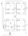
- FIG. 1 is a circuit diagram of a module 1102 of a sodium sulfur battery. As shown in FIG. 1, the module 1102 is a serial connection body in which blocks 1104 are connected in series, the block 1104 is a parallel connection body in which strings 1106 are connected in parallel, and the string 1106 is a direct connection in which cells 1108 are connected in series. It is a connected body.
- FIG. 1 shows a case where the number of serial connections of the block 1104 is 4, but the number of serial connections of the block 1104 is increased or decreased according to the module specifications.
- the number of parallel connections NP of strings 1106 is the same for all blocks 1104, and the number of series connections NS of cells 1108 is the same for all strings 1106.
- the number of parallel connections NP of the strings 1106 and the number of series connections NS of the cells 1108 are also increased or decreased according to the specifications of the module.
- the number of parallel connections NP of the strings 1106 and the number of series connections NS of the cells 1108 are typically 2 or more. However, correction of the ohmic resistance RO, which will be described later, can also be performed when the number NS of cells 1108 connected in series is 1, that is, when the block 1104 is a parallel connection of cells 1108.
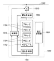
- FIG. 2 is a block diagram of the control device 1002 of the preferred embodiment for controlling the module 1102 and the charging / discharging of the module 1102. As shown in FIG. 2, the control device 1002 measures the temperature of each of the voltage measurement unit 1004 that measures the voltage of each block 1104, the current measurement unit 1006 that measures the charging / discharging current of the module 1102, and the block 1104.
- a temperature measuring unit 1008 that performs conversion from DC to AC when power is supplied from the module 1102 to the power system 1902 and conversion from AC to DC when power is supplied from the power system 1902 to the module 1102
- a direction converter 1010 and a control unit 1012 that acquires measurement results of the voltage measurement unit 1004, the current measurement unit 1006, and the temperature measurement unit 1008 and controls the bidirectional converter 1010. Since the module 1102 is a serial connection body of the block 1104, the charging / discharging current of the module 1102 measured by the current measuring unit 1006 is regarded as the charging / discharging current of the block 1104.
- control unit 1002 controls the bidirectional converter 1010 to stop the discharge of the module 1102.
- FIG. 3 is a block diagram of the control unit 1012. Each of the blocks in FIG. 3 may be realized by causing an embedded computer including at least a CPU and a memory to execute a program, or may be realized by hardware.
- the control unit 1012 includes an end-of-discharge voltage correction unit 1020 that corrects the end-of-discharge voltage VL.
- the end-of-discharge voltage correction unit 1020 separates the internal resistance R of the module 1102 into an ohmic resistance RO and a polarization resistance RP.
- the end-of-discharge voltage correction unit 1020 calculates the product I ⁇ RO of the discharge current I of the block 1104 and the ohmic resistance RO of the block 1104 obtained from the current measurement unit 1006 and the discharge current I of the block 1104 according to the equation (1).
- the product ITD ⁇ RP of the discharge current ITD subjected to the time delay process and the polarization resistance RP of the block 1104 is subtracted from the discharge end open voltage VLOC to be the end discharge voltage VL.
- the discharge current I is an actual measurement value measured by the current measurement unit 1006 and is a function of time.
- the time delay processing is processing such as integral average and moving average with respect to time.
- the discharge current ITD subjected to the time delay process is a calculated value reflecting the past discharge current I and is a function of time.
- the ohmic resistance RO is an estimated value estimated from the equivalent cycle number CY and the healthy parallel number NPS of the block 1104.
- the polarization resistance RP is a set value.
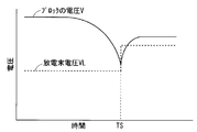
- FIG. 4 is a diagram for explaining a disadvantage in correcting the end-of-discharge voltage VL without considering the polarization resistance RP.
- FIG. 6 is a graph showing the change with time of the discharge current I in the block 1104.
- the voltage V of the block 1104 decreases with the passage of time, and after the timing TS, the block V The voltage V of 1104 recovers with time.
- the end-of-discharge voltage VL when correcting the end-of-discharge voltage VL without considering the polarization resistance RP, as shown in FIG. 4, the end-of-discharge voltage VL rapidly increases at the timing TS, so that the voltage of the block 1104 before the timing TS. Even though V is not lower than the end-of-discharge voltage VL, the voltage V of the block 1104 may fall below the end-of-discharge voltage VL after the timing TS.
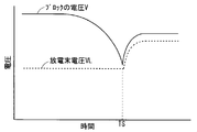
- the end-of-discharge voltage VL when the end-of-discharge voltage VL is corrected in consideration of the polarization resistance RP, as shown in FIG. 5, the end-of-discharge voltage VL does not rapidly increase at the timing TS, so the voltage V of the block 1104 before the timing TS. Is less than the end-of-discharge voltage VL, the voltage V of the block 1104 is less likely to fall below the end-of-discharge voltage VL after the timing TS. That is, erroneous detection of the end of discharge is suppressed.
- control unit 1012 further includes an ohmic resistance correction unit 1022 that corrects the ohmic resistance RO.
- the ohmic resistance correction unit 1022 increases the ohmic resistance RO as the equivalent cycle number CY derived by the equivalent cycle number deriving unit 1028 increases, and decreases as the healthy parallel number NPH derived by the healthy parallel number deriving unit 1038 decreases.
- Increase ohmic resistance RO “Derivation” refers to processing such as computation by an arithmetic expression in a built-in computer that executes a control program, conversion by a table, computation by an analog arithmetic circuit, and the like.
- the equivalent cycle number CY is the number of charge / discharge cycles in which the block 1104 deteriorates to approximately the same degree of deterioration when discharge of approximately the same capacity as the rated capacity is repeated for each charge / discharge cycle.
- the equivalent cycle number CY takes a value different from the actual charge / discharge cycle number and takes a value other than the natural number.
- the equivalent cycle number CY increases as the number of charge / discharge cycles increases.
- the increment ⁇ CY of the number of equivalent cycles CY in each charge / discharge cycle takes a value from 0 to 1, and increases as the discharge depth DD increases.
- the equivalent cycle number CY more appropriately reflects the deterioration of the block 1104 than the charge / discharge cycle number. For this reason, when the ohmic resistance RO is corrected based on the equivalent cycle number CY, the ohmic resistance RO is accurately corrected, so that the end-of-discharge voltage VL is accurately corrected.
- the sound parallel number NPH is the number of parallel strings 1106 that can obtain the same capacity when the block 1104 is a parallel connection body including only the sound strings 1106.
- the healthy parallel number NPH takes a value different from the actual parallel number NP of the string 1106 and takes a value other than a natural number.
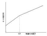
- FIG. 7 is a graph showing a desirable relationship between the equivalent cycle number CY and the ohmic resistance RO when the healthy parallel number NPH does not change.
- the increase coefficient dRO / dCY of the ohmic resistance RO relative to the equivalent cycle CY that is, the slope of the graph of FIG. It is desirable to make it smaller.
- the increase coefficient dRO / dCY and the threshold value TCY depend on the specifications of the cell 1108.
- the increase coefficient dRO / dCY may be switched to three or more stages instead of switching to two stages.
- the ohmic resistance RO is the sum of the first term depending on the equivalent cycle number CY and the healthy parallel number NPH and the second term depending on the temperature TEMP of the module 1102, as shown in the equation (2).
- the set values K1, K2, and K3 depend on the specifications of the cell 1108.
- the temperature TEMP is an actual measurement value measured by the temperature measurement unit 1008 and is a function of time.
- the variation factor RCN of the first term depending on the equivalent cycle number CY and the healthy parallel number NPH is derived according to the equation (3) when the equivalent cycle number CY is less than the threshold value TCY, and the equivalent cycle number CY is calculated as the threshold value TCY. If this is the case, it is derived according to equation (4).
- the variation factor RCN is a linear function of the equivalent cycle number CY, and is a ⁇ 1 order function of the healthy parallel number NPH.
- the set values K4, K5, K6, and K7 depend on the specifications of the cell 1108. In order to make the increase coefficient dRO / dCY smaller when the equivalent cycle number CY exceeds the threshold value TCY than when the equivalent cycle number CY falls below the threshold value TCY, the set value K7 is made smaller than the set value K5.
- the control unit 1012 calculates a discharge depth derivation unit 1024 that derives the discharge depth DD of the block 1104 for each charge / discharge cycle, and an increment ⁇ CY of the equivalent cycle number CY.
- An increment deriving unit 1026 for deriving each charge / discharge cycle and an equivalent cycle number deriving unit 1028 for deriving the equivalent cycle number CY are provided.
- the discharge depth deriving unit 1024 integrates the discharge current I of the block 1104 at time t from the discharge start time T0 to the discharge end time T1 according to the equation (5), and the discharge depth expressed by the discharged capacity (Ah). DC is derived. In order to reduce the error, the integration of the discharge current I may be stopped while the discharge current I is below the threshold value.
- the discharge depth deriving unit 1024 derives the discharge depth DD expressed as a ratio to the rated capacity DCR of the block 1104 according to the equation (6). This conversion of the expression of the depth of discharge is not always necessary.
- the increment deriving unit 1026 increases the increment ⁇ CY of the equivalent cycle number CY as the discharge depth DD derived by the discharge depth deriving unit 1024 becomes deeper.
- FIG. 8 is a graph showing a desirable relationship between the discharge depth DD and the increment ⁇ CY.
- the increase coefficient d ⁇ CY / dDD of the increase ⁇ CY relative to the discharge depth DD that is, the slope of the graph of FIG. 8 is smaller when the discharge depth DD is higher than the threshold TDD1 than when the discharge depth DD is lower than the threshold TDD1. It is desirable.
- the increase coefficient d ⁇ CY / dDD is further reduced when the discharge depth DD exceeds the threshold value TDD2 than when the discharge depth DD falls below the threshold value TDD2 set larger than the threshold value TDD1.
- the ohmic resistance RO is accurately corrected by decreasing the increase coefficient d ⁇ CY / dDD as the discharge depth DD becomes deeper, so that the end-of-discharge voltage VL is accurately corrected.
- the specific values of the increase coefficient d ⁇ CY / dDD and the threshold values TDD 1 and TDD 2 depend on the specifications of the cell 1108.
- the increase coefficient d ⁇ CY / dDD may be switched to two stages or four or more stages instead of switching to three stages.
- the increment ⁇ CY is derived according to Equation (7) when the discharge depth DD is less than the threshold value TDD1, and is derived according to Equation (8) when the discharge depth DD is equal to or greater than the threshold value TDD1 and less than TDD2.
- DD is equal to or greater than threshold value TDD2
- it is calculated according to equation (9).
- the set values K8, K9, and K10 depend on the specifications of the cell 1108. In order to decrease the increase coefficient d ⁇ CY / dDD as the discharge depth DD becomes deeper, the set value K10 is set larger than 0 and smaller than the set value K8.
- the equivalent cycle number deriving unit 1028 adds the increment ⁇ CY derived by the increment deriving unit 1026 to derive the equivalent cycle number CY.
- the equivalent cycle number CY (n) in the nth charge / discharge cycle is the increment in the nth charge / discharge cycle to the equivalent cycle number CY (n-1) in the n ⁇ 1th charge / discharge cycle according to the equation (10). It is derived by adding ⁇ CY (n).
- the control unit 1012 derives the healthy parallel number NPH, an information holding unit 1030 that holds information indicating the relationship between the discharge depth and the open circuit voltage, and a target for correcting the end-of-discharge voltage VL.
- Target block absolute depth deriving unit 1032 for deriving absolute depth ADS after the end of discharge of block 1104 (hereinafter referred to as “target block”), and block 1104 serving as a reference for comparison (hereinafter referred to as “reference block”) )
- a reference block absolute depth derivation unit 1034 for deriving an absolute depth ADR after the end of discharge a ratio derivation unit 1036 for deriving a ratio R of the healthy parallel number NPH of the target block to the healthy parallel number NPHR of the reference block, and a target A sound parallel number deriving unit 1038 for deriving a healthy parallel number NPH of a block, and a reference block selecting unit 104 for selecting a reference block And, equipped with a.
- the controller 1012 derives the healthy parallel number NPH of all the blocks 1104 for each charge / discharge cycle.
- the information holding unit 1030 holds information indicating the relationship between the open circuit voltage of the block 1104 and the discharge depth of the cells 1108 that constitute the block 1104.
- the depth of discharge is expressed by the discharged capacity (Ah).
- the information may be stored as a numerical table or may be stored as an arithmetic expression.
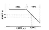
- FIG. 9 is a graph showing information on the relationship between the open circuit voltage of the block 1104 held in the information holding unit 1030 and the discharge depth of the cells 1108 constituting the block 1104.
- the open-circuit voltage is increased even when the discharge depth is deep. Is generally constant.
- the open circuit voltage decreases as the discharge depth increases. Therefore, if the open circuit voltage of the block 1104 after the end of discharge is known, the absolute depth of the block 1104 is derived by referring to the information on the relationship between the open circuit voltage of the block 1104 and the discharge depth of the cells 1108 constituting the block 1104. Is done.
- the “absolute depth” of the block 1104 indicates where the cell 1108 belonging to the healthy string 1106 constituting the block 1104 is on the horizontal axis of the graph of FIG. Therefore, even if the discharged capacity of the block 1104 is the same, if the healthy parallel number NPH increases, the absolute depth of the block 1104 becomes shallow (to the left in the graph of FIG. 9), and the healthy parallel number NPH decreases. If this is the case, the absolute depth of the block 1104 will be deeper (to the right in the graph of FIG. 9). This means that the healthy parallel number NPH is obtained from the absolute depth after the end of discharge of the target block and the reference block having the same actual capacity from the start of discharge to the end of discharge, that is, the target block and reference block connected in series. It means to go.
- Information on the relationship between the open circuit voltage of the block 1104 and the discharge depth of the cell 1108 constituting the block 1104 is determined by the specification of the cell 1108 and does not depend on the healthy parallel number NPH.
- the information indicating the relationship between the open circuit voltage of the block 1104 and the discharge depth of the cell 1108 constituting the block 1104 is used.
- the relationship between the open circuit voltage of the block 1104 and the discharge depth of the block 1104 is illustrated.
- Information may be used. This is because the information indicating the relationship between the open circuit voltage of the block 1104 and the discharge depth of the block 1104 is only represented by a graph obtained by multiplying the graph of FIG. 9 by the number NP of parallel connections of the strings 1106 in the horizontal axis direction.
- the healthy parallel number NPH is actually calculated between the target block and the reference block.
- the target block absolute depth deriving unit 1032 refers to the information held by the information holding unit 1030 and, as shown in FIG. 9, determines the absolute discharge depth of the target block corresponding to the open circuit voltage VS after the discharge of the target block is completed. Derived as depth ADS.
- the “open circuit voltage after the end of discharge” may be an actually measured value after a sufficient time has elapsed from the end of discharge, or an estimated value estimated from fluctuations in the open circuit voltage after the end of discharge. Also good.
- the reference block absolute depth deriving unit 1034 refers to the information held by the information holding unit 1030 and, as shown in FIG. 9, calculates the absolute discharge depth of the target block corresponding to the open circuit voltage VR after the completion of the discharge of the reference block. Derived as depth ADR.
- the “open circuit voltage after the end of discharge” may also be an actually measured value or an estimated value.
- the information referred to by the reference block absolute depth deriving unit 1034 is the same information as the information referred to by the target block absolute depth deriving unit 1032.
- the capacity (hereinafter referred to as “used capacity”) DC that the block 1104 actually discharges from the start of discharge to the end of discharge is the DC between the target block and the reference block.
- the open circuit voltage VS after the end of the discharge of the target block is the open circuit voltage after the end of the discharge of the reference block.
- the absolute depth ADS derived by the target block absolute depth deriving unit 1032 becomes lower than the VR and becomes deeper than the absolute depth ADR derived by the reference block absolute depth deriving unit 1034.
- the ratio deriving unit 1036 derives the capacity CPS of the target block that is discharged until the target block reaches the absolute depth ADR when it is assumed that the healthy parallel number NPH of the target block is the same as the healthy parallel number NPHR of the reference block. .
- the capacity CPS of the target block for example, the capacity difference obtained by multiplying the difference ADS ⁇ ADR between the absolute depth ADS and the absolute depth ADR by the healthy parallel number NPHR (n ⁇ 1) derived in the previous charge / discharge cycle of the reference block The sum of (ADS ⁇ ADR) ⁇ NPHR (n ⁇ 1) and the used capacity DC + (ADS ⁇ ADR) ⁇ NPHR (n ⁇ 1) is employed.
- the information indicating the relationship between the open circuit voltage of the block 1104 and the discharge depth of the block 1104 it is not necessary to multiply the healthy parallel number NPHR (n ⁇ 1) of the reference block.
- the ratio deriving unit 1036 derives the capacity CPR of the reference block that is discharged from the start of discharge to the absolute depth ADR.
- the used capacity DC itself is employed as the capacity CPR of the reference block.
- the ratio deriving unit 1036 derives the ratio R of the capacity CPR of the reference block to the capacity CPS of the target block according to the equation (11).
- the ratio deriving unit 1036 multiplies the derived ratio R by the healthy parallel number NPHR (n ⁇ 1) derived in the previous charging / discharging cycle of the reference block according to the equation (12), and the current charging of the target block.
- the healthy parallel number NPHS (n) of the discharge cycle is derived.
- the reference block selection unit 1040 selects a block 1104 with less deterioration as a reference block. For example, the reference block selection unit 1040 sets one block 1104 having the largest healthy parallel number NPH derived in the previous charge / discharge cycle as the reference block. Alternatively, the reference block selection unit 1040 sets one block 1104 selected from two or more blocks 1104 having a relatively large healthy parallel number NPH derived in the previous charge / discharge cycle as a reference block.
- one block 1104 is selected from the blocks 1104 as a reference block.
- the temporary healthy parallel number NPH of the second block 1104 is derived using the first block 1104 as a temporary reference block.
- the first block 1104 is regarded as a reference block and the second block 1104 is regarded as a target block, and the expressions (11) and (12) described above are used.
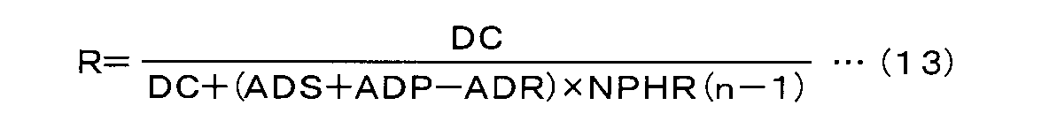
- the equation (13) further introducing the parameter ADP for suppressing the first block 1104 from being determined to be deteriorated may be used. desirable.
- the provisional healthy parallel number NPH of the second block 1104 derived according to the equations (12) and (13) is compared with the healthy parallel number NPH of the second block 1104 derived in the previous charge / discharge cycle.
- the former is greater than the latter, the second block 1104 is the reference block, otherwise, the first block 1104 is the reference block.
Landscapes
- Engineering & Computer Science (AREA)
- Power Engineering (AREA)
- Manufacturing & Machinery (AREA)
- Chemical & Material Sciences (AREA)
- Chemical Kinetics & Catalysis (AREA)
- Electrochemistry (AREA)
- General Chemical & Material Sciences (AREA)
- Physics & Mathematics (AREA)
- General Physics & Mathematics (AREA)
- Secondary Cells (AREA)
- Charge And Discharge Circuits For Batteries Or The Like (AREA)
Abstract
放電末電圧が適切に補正される放電末電圧補正装置及び放電末電圧補正方法を提供する。放電末電圧補正部は、ブロックの放電電流Iとブロックのオーミック抵抗ROとの積I×RO及びブロックの放電電流Iに対して時間遅れ処理を施した放電電流ITDとブロックの分極抵抗RPとの積ITD×RPを放電末開放電圧VLOCから引き放電末電圧VLとする。オーミック抵抗ROは、等価サイクル数CYが増加するほど増加し、健全並列数NPHが減少するほど増加する。充放電サイクルの各々における等価サイクル数CYの増分ΔCYは、放電深度DDが深くなるほど大きくなる。健全並列数NPHは、対象ブロックの容量CPSに対する基準ブロックの容量CPRの比を基準ブロックの健全並列数NPHRに掛けることにより導出される。
Description
本発明は、ナトリウムイオウ電池のセル又はセルの直列接続体を並列接続した並列接続体の放電末電圧を補正する放電末電圧補正装置及び放電末電圧補正方法に関する。
特許文献1及び特許文献2は、ナトリウムイオウ電池の放電を中止する放電末電圧の補正に関する。
特許文献1の放電末電圧の補正は、内部抵抗をオーミック抵抗と分極抵抗とに分離し、放電電流とオーミック抵抗との積及び時間遅れ処理を施した放電電流と分極抵抗との積を放電末開放電圧から引き放電末電圧とする。
また、特許文献2の放電末電圧の補正は、内部抵抗と放電電流との積を放電末開放電圧から引き放電末電圧とする。内部抵抗は、充放電サイクル数及び健全並列数で補正される。
従来の放電末電圧の補正には、内部抵抗が適切に補正されないため、放電末電圧が適切に補正されないという問題がある。これは、従来の技術における充放電サイクル数及び健全並列数が内部抵抗を正確に反映しない場合があるからである。
本発明は、この問題を解決するためになされたもので、放電末電圧が適切に補正される放電末電圧補正装置及び放電末電圧補正方法を提供することを目的とする。
上記課題を解決するため、第1の発明は、ナトリウムイオウ電池のセル又はセルの直列接続体を並列接続した第1の並列接続体の放電末電圧を補正する放電末電圧補正装置であって、第1の並列接続体の放電深度を充放電サイクルごとに導出する放電深度導出部と、前記放電深度導出部により導出された放電深度が深くなるほど大きくなる等価サイクル数の増分を充放電サイクルごとに導出する増分導出部と、前記増分導出部により導出された増分を加算し等価サイクル数を導出する等価サイクル数導出部と、開放電圧と放電深度との関係を示す情報を保持する情報保持部と、前記情報保持部により保持された情報を参照し第1の並列接続体の放電終了の後の開放電圧に対応する第1の並列接続体の放電深度を絶対深度として導出する第1の絶対深度導出部と、前記情報保持部により保持され前記第1の絶対深度導出部により参照される情報を参照し第1の並列接続体に直列接続された第2の並列接続体の放電終了後の開放電圧に対応する第2の並列接続体の放電深度を絶対深度として導出する第2の絶対深度導出部と、第1の並列接続体の健全並列数が第2の並列接続体の健全並列数と同じであると仮定した場合に第1の並列接続体が放電開始から前記第1の絶対深度導出部により導出された絶対深度に至るまでに放電する容量に対する第2の並列接続体が放電開始から前記第2の絶対深度導出部により導出された絶対深度に至るまでに放電する容量の比を導出する比導出部と、前記比導出部により導出された比を第2の並列接続体の健全並列数に掛け第1の並列接続体の健全並列数を導出する健全並列数導出部と、前記等価サイクル数導出部により導出された等価サイクル数が増加するほど第1の並列接続体のオーミック抵抗の推定値を増加させ前記健全並列数導出部により導出された健全並列数が減少するほど第1の並列接続体のオーミック抵抗の推定値を増加させるオーミック抵抗補正部と、第1の並列接続体の放電電流と前記オーミック抵抗補正部により補正された第1の並列接続体のオーミック抵抗の推定値との積及び時間遅れ処理を施した第1の並列接続体の放電電流と第1の並列接続体の分極抵抗との積を放電末開放電圧から引き放電末電圧とする放電末電圧補正部と、を備える。
第2の発明は、第1の発明の放電末電圧補正装置において、前記増分導出部は、前記放電深度導出部により導出された放電深度が深くなるほど放電深度に対する増分の増加係数を小さくする。
第3の発明は、第1又は第2の発明の放電末電圧補正装置において、前記オーミック抵抗補正部は、前記等価サイクル数導出部により導出された等価サイクル数が増加するほど等価サイクル数に対するオーミック抵抗の推定値の増加係数を小さくする。
第4の発明は、ナトリウムイオウ電池のセル又はセルの直列接続体を並列接続した第1の並列接続体の放電末電圧を補正する放電末電圧補正方法であって、(a) 第1の並列接続体の放電深度を充放電サイクルごとに導出する工程と、(b) 前記工程(a)により導出された放電深度が深くなるほど大きくなる等価サイクル数の増分を充放電サイクルごとに導出する工程と、(c) 前記工程(b)により導出された増分を加算し等価サイクル数を導出する工程と、(d) 開放電圧と放電深度との関係を示す情報を参照し第1の並列接続体の放電終了の後の開放電圧に対応する第1の並列接続体の絶対深度を導出する工程と、(e) 前記工程(d)により参照された情報を参照し第1の並列接続体に直列接続された第2の並列接続体の放電終了後の開放電圧に対応する第2の並列接続体の絶対深度を導出する工程と、(f) 第1の並列接続体の健全並列数が第2の並列接続体の健全並列数と同じであると仮定した場合に第1の並列接続体が放電開始から前記工程(d)により導出された絶対深度に至るまでに放電する容量に対する第2の並列接続体が放電開始から前記工程(e)により導出された絶対深度に至るまでに放電する容量の比を導出する工程と、(g) 前記工程(f)により導出された比を第2の並列接続体の健全並列数に掛け第1の並列接続体の健全並列数を導出する工程と、(h) 前記工程(c)により導出された等価サイクル数が増加するほど第1の並列接続体のオーミック抵抗の推定値を増加させ前記工程(g)により導出された健全並列数が減少するほど第1の並列接続体のオーミック抵抗の推定値を増加させる工程と、(i) 第1の並列接続体の放電電流と前記工程(g)により補正された第1の並列接続体のオーミック抵抗の推定値との積及び時間遅れ処理を施した第1の並列接続体の放電電流と第1の並列接続体の分極抵抗との積を放電末開放電圧から引き放電末電圧とする工程と、を備える。
本発明によれば、オーミック抵抗が正確に補正されるので、放電末電圧が正確に補正される。
この発明の目的、特徴、局面及び利点は、以下の詳細な説明と添付図面とによって、より明白となる。
(ナトリウムイオウ電池のモジュール1102)
図1は、ナトリウムイオウ電池のモジュール1102の回路図である。図1に示すように、モジュール1102は、ブロック1104を直列接続した直列接続体であり、ブロック1104は、ストリング1106を並列接続した並列接続体であり、ストリング1106は、セル1108を直列接続した直接接続体である。
図1は、ナトリウムイオウ電池のモジュール1102の回路図である。図1に示すように、モジュール1102は、ブロック1104を直列接続した直列接続体であり、ブロック1104は、ストリング1106を並列接続した並列接続体であり、ストリング1106は、セル1108を直列接続した直接接続体である。
図1は、ブロック1104の直列接続数が4である場合を示しているが、ブロック1104の直列接続数はモジュールの仕様に応じて増減される。
ストリング1106の並列接続数NPは全部のブロック1104について同じであり、セル1108の直列接続数NSは全部のストリング1106について同じである。ストリング1106の並列接続数NP及びセル1108の直列接続数NSもモジュールの仕様に応じて増減される。ストリング1106の並列接続数NP及びセル1108の直列接続数NSは、典型的には、2以上である。ただし、後述するオーミック抵抗ROの補正は、セル1108の直列接続数NSが1である場合、すなわち、ブロック1104がセル1108の並列接続体である場合にも実施しうる。
(制御装置1002の概略)
図2は、モジュール1102及びモジュール1102の充放電を制御する望ましい実施形態の制御装置1002のブロック図である。図2に示すように、制御装置1002は、ブロック1104の各々の電圧を測定する電圧計測部1004と、モジュール1102の充放電電流を計測する電流計測部1006と、ブロック1104の各々の温度を測定する温度計測部1008と、モジュール1102から電力系統1902へ電力を供給するときに直流から交流への変換を行い電力系統1902からモジュール1102へ電力を供給するときに交流から直流への変換を行う双方向変換器1010と、電圧計測部1004、電流計測部1006及び温度計測部1008の計測結果を取得し、双方向変換器1010を制御する制御部1012とを備える。モジュール1102はブロック1104の直列接続体であるので、電流計測部1006により計測されるモジュール1102の充放電電流はブロック1104の充放電電流とみなされる。
図2は、モジュール1102及びモジュール1102の充放電を制御する望ましい実施形態の制御装置1002のブロック図である。図2に示すように、制御装置1002は、ブロック1104の各々の電圧を測定する電圧計測部1004と、モジュール1102の充放電電流を計測する電流計測部1006と、ブロック1104の各々の温度を測定する温度計測部1008と、モジュール1102から電力系統1902へ電力を供給するときに直流から交流への変換を行い電力系統1902からモジュール1102へ電力を供給するときに交流から直流への変換を行う双方向変換器1010と、電圧計測部1004、電流計測部1006及び温度計測部1008の計測結果を取得し、双方向変換器1010を制御する制御部1012とを備える。モジュール1102はブロック1104の直列接続体であるので、電流計測部1006により計測されるモジュール1102の充放電電流はブロック1104の充放電電流とみなされる。
(放電の中止)
制御部1002は、電圧計測部1004から取得したブロック1104の電圧が放電末電圧VLを下回ると、双方向変換器1010を制御し、モジュール1102の放電を中止させる。
制御部1002は、電圧計測部1004から取得したブロック1104の電圧が放電末電圧VLを下回ると、双方向変換器1010を制御し、モジュール1102の放電を中止させる。
(制御部1012の概略)
図3は、制御部1012のブロック図である。図3のブロックの各々は、少なくともCPU及びメモリを備える組み込みコンピュータにプログラムを実行させることにより実現されてもよいし、ハードウエアにより実現されてもよい。
図3は、制御部1012のブロック図である。図3のブロックの各々は、少なくともCPU及びメモリを備える組み込みコンピュータにプログラムを実行させることにより実現されてもよいし、ハードウエアにより実現されてもよい。
(放電末電圧補正部1020)
図3に示すように、制御部1012は、放電末電圧VLを補正する放電末電圧補正部1020を備える。放電末電圧補正部1020は、モジュール1102の内部抵抗Rをオーミック抵抗ROと分極抵抗RPとに分離する。放電末電圧補正部1020は、式(1)にしたがって、電流計測部1006から取得したブロック1104の放電電流Iとブロック1104のオーミック抵抗ROとの積I×RO及びブロック1104の放電電流Iに対して時間遅れ処理を施した放電電流ITDとブロック1104の分極抵抗RPとの積ITD×RPを放電末開放電圧VLOCから引き放電末電圧VLとする。
図3に示すように、制御部1012は、放電末電圧VLを補正する放電末電圧補正部1020を備える。放電末電圧補正部1020は、モジュール1102の内部抵抗Rをオーミック抵抗ROと分極抵抗RPとに分離する。放電末電圧補正部1020は、式(1)にしたがって、電流計測部1006から取得したブロック1104の放電電流Iとブロック1104のオーミック抵抗ROとの積I×RO及びブロック1104の放電電流Iに対して時間遅れ処理を施した放電電流ITDとブロック1104の分極抵抗RPとの積ITD×RPを放電末開放電圧VLOCから引き放電末電圧VLとする。
放電電流Iは、電流計測部1006により計測される実測値であり、時間の関数である。時間遅れ処理は、時間についての積分平均、移動平均等の処理である。時間遅れ処理を施した放電電流ITDは、過去の放電電流Iを反映する演算値であり、時間の関数である。オーミック抵抗ROは、ブロック1104の等価サイクル数CY及び健全並列数NPSから推定される推定値である。分極抵抗RPは設定値である。
(分極抵抗RPを考慮して放電末電圧VLを補正する利点)
図4は、分極抵抗RPを考慮しないで放電末電圧VLを補正する場合の不利な点を説明する図である。図5は、分極抵抗RPを考慮して放電末電圧VLを補正する場合の有利な点を説明する図である。図4及び図5は、ブロック1104の電圧V及び放電末電圧VLの時間変化を示すグラフである。図6は、ブロック1104の放電電流Iの時間変化を示すグラフである。
図4は、分極抵抗RPを考慮しないで放電末電圧VLを補正する場合の不利な点を説明する図である。図5は、分極抵抗RPを考慮して放電末電圧VLを補正する場合の有利な点を説明する図である。図4及び図5は、ブロック1104の電圧V及び放電末電圧VLの時間変化を示すグラフである。図6は、ブロック1104の放電電流Iの時間変化を示すグラフである。
図6に示すブロック1104の放電が中止されるタイミングTSより前においては、図4及び図5に示すように、ブロック1104の電圧Vは時間の経過とともに低下し、タイミングTSより後においては、ブロック1104の電圧Vは時間の経過とともに回復する。
このため、分極抵抗RPを考慮しないで放電末電圧VLを補正する場合は、図4に示すように、タイミングTSに放電末電圧VLが急激に上昇するので、タイミングTSより前においてブロック1104の電圧Vが放電末電圧VLを下回っていないにもかかわらず、タイミングTSより後においてブロック1104の電圧Vが放電末電圧VLを下回ることがある。
一方、分極抵抗RPを考慮して放電末電圧VLを補正する場合は、図5に示すように、タイミングTSに放電末電圧VLが急激に上昇しないので、タイミングTSより前においてブロック1104の電圧Vが放電末電圧VLを下回っていないにもかかわらず、タイミングTSより後においてブロック1104の電圧Vが放電末電圧VLを下回ることが少なくなる。つまり、放電末の誤検出が抑制される。
(オーミック抵抗補正部1022)
図3に示すように、制御部1012は、オーミック抵抗ROを補正するオーミック抵抗補正部1022をさらに備える。オーミック抵抗補正部1022は、等価サイクル数導出部1028により導出された等価サイクル数CYが増加するほどオーミック抵抗ROを増加させ、健全並列数導出部1038により導出された健全並列数NPHが減少するほどオーミック抵抗ROを増加させる。「導出」とは、制御プログラムを実行する組み込みコンピュータにおける演算式による演算やテーブルによる変換、アナログ演算回路による演算等の処理をいう。
図3に示すように、制御部1012は、オーミック抵抗ROを補正するオーミック抵抗補正部1022をさらに備える。オーミック抵抗補正部1022は、等価サイクル数導出部1028により導出された等価サイクル数CYが増加するほどオーミック抵抗ROを増加させ、健全並列数導出部1038により導出された健全並列数NPHが減少するほどオーミック抵抗ROを増加させる。「導出」とは、制御プログラムを実行する組み込みコンピュータにおける演算式による演算やテーブルによる変換、アナログ演算回路による演算等の処理をいう。
(等価サイクル数CY)
等価サイクル数CYは、定格容量と略同一の容量の放電を充放電サイクルごとに繰り返した場合に略同一の劣化の度合いまでブロック1104が劣化する充放電サイクル数である。等価サイクル数CYは、実際の充放電サイクル数とは異なる値をとり、自然数以外の値もとる。
等価サイクル数CYは、定格容量と略同一の容量の放電を充放電サイクルごとに繰り返した場合に略同一の劣化の度合いまでブロック1104が劣化する充放電サイクル数である。等価サイクル数CYは、実際の充放電サイクル数とは異なる値をとり、自然数以外の値もとる。
等価サイクル数CYは、充放電サイクル数が増加するほど増加する。充放電サイクルの各々における等価サイクル数CYの増分ΔCYは、0から1までの値をとり、放電深度DDが深くなるほど大きくなる。等価サイクル数CYは、充放電サイクル数よりもブロック1104の劣化を適切に反映する。このため、等価サイクル数CYに基づいてオーミック抵抗ROを補正すると、オーミック抵抗ROが正確に補正されるので、放電末電圧VLが正確に補正される。
(健全並列数NPH)
健全並列数NPHは、ブロック1104が健全なストリング1106のみからなる並列接続体である場合に同一の容量が得られるストリング1106の並列数である。健全並列数NPHは、ストリング1106の実際の並列数NPとは異なる値をとり、自然数以外の値もとる。
健全並列数NPHは、ブロック1104が健全なストリング1106のみからなる並列接続体である場合に同一の容量が得られるストリング1106の並列数である。健全並列数NPHは、ストリング1106の実際の並列数NPとは異なる値をとり、自然数以外の値もとる。
(等価サイクル数CYとオーミック抵抗ROとの関係)
図7は、健全並列数NPHが変化しない場合の等価サイクル数CYとオーミック抵抗ROとの望ましい関係を示すグラフである。図7に示すように、等価サイクル数CYが閾値TCYを下回る場合よりも閾値TCYを上回る場合の方が等価サイクルCYに対するオーミック抵抗ROの増加係数dRO/dCY、すなわち、図7のグラフの傾きが小さくなることが望ましい。このように等価サイクル数CYが増加するほど増加係数dRO/dCYを小さくすることにより、オーミック抵抗ROが正確に補正されるので、放電末電圧VLが正確に補正される。増加係数dRO/dCY及び閾値TCYの具体値は、セル1108の仕様に左右される。増加係数dRO/dCYを2段階に切り替えるのではなく3段階以上に切り替えてもよい。
図7は、健全並列数NPHが変化しない場合の等価サイクル数CYとオーミック抵抗ROとの望ましい関係を示すグラフである。図7に示すように、等価サイクル数CYが閾値TCYを下回る場合よりも閾値TCYを上回る場合の方が等価サイクルCYに対するオーミック抵抗ROの増加係数dRO/dCY、すなわち、図7のグラフの傾きが小さくなることが望ましい。このように等価サイクル数CYが増加するほど増加係数dRO/dCYを小さくすることにより、オーミック抵抗ROが正確に補正されるので、放電末電圧VLが正確に補正される。増加係数dRO/dCY及び閾値TCYの具体値は、セル1108の仕様に左右される。増加係数dRO/dCYを2段階に切り替えるのではなく3段階以上に切り替えてもよい。
(オーミック抵抗ROの補正式の例)
オーミック抵抗ROの補正式の例を説明する。ただし、ここで説明する補正式以外の補正式も採用しうる。
オーミック抵抗ROの補正式の例を説明する。ただし、ここで説明する補正式以外の補正式も採用しうる。
オーミック抵抗ROは、式(2)に示すように、等価サイクル数CY及び健全並列数NPHに依存する第1項とモジュール1102の温度TEMPに依存する第2項との和である。設定値K1,K2,K3は、セル1108の仕様に左右される。温度TEMPは、温度計測部1008により計測される実測値であり、時間の関数である。

等価サイクル数CY及び健全並列数NPHに依存する第1項の変動因子RCNは、等価サイクル数CYが閾値TCY未満である場合は、式(3)にしたがって導出され、等価サイクル数CYが閾値TCY以上である場合は、式(4)にしたがって導出される。変動因子RCNは、等価サイクル数CYの1次の関数であり、健全並列数NPHの-1次の関数である。設定値K4,K5,K6,K7は、セル1108の仕様に左右される。等価サイクル数CYが閾値TCYを下回る場合よりも閾値TCYを上回る場合の方が増加係数dRO/dCYが小さくなるようにするためには、設定値K7を設定値K5よりも小さくする。


(等価サイクル数CYの導出)
図3に示すように、制御部1012は、等価サイクル数CYを導出するため、ブロック1104の放電深度DDを充放電サイクルごとに導出する放電深度導出部1024と、等価サイクル数CYの増分ΔCYを充放電サイクルごとに導出する増分導出部1026と、等価サイクル数CYを導出する等価サイクル数導出部1028と、を備える。
図3に示すように、制御部1012は、等価サイクル数CYを導出するため、ブロック1104の放電深度DDを充放電サイクルごとに導出する放電深度導出部1024と、等価サイクル数CYの増分ΔCYを充放電サイクルごとに導出する増分導出部1026と、等価サイクル数CYを導出する等価サイクル数導出部1028と、を備える。
(放電深度導出部1024)
放電深度導出部1024は、式(5)にしたがって、ブロック1104の放電電流Iを時間tで放電開始時T0から放電終了時T1まで積分し、放電された容量(Ah)で表現された放電深度DCを導出する。誤差を減らすため、放電電流Iが閾値を下回っている間は放電電流Iの積分を停止してもよい。
放電深度導出部1024は、式(5)にしたがって、ブロック1104の放電電流Iを時間tで放電開始時T0から放電終了時T1まで積分し、放電された容量(Ah)で表現された放電深度DCを導出する。誤差を減らすため、放電電流Iが閾値を下回っている間は放電電流Iの積分を停止してもよい。

また、放電深度導出部1024は、式(6)にしたがって、ブロック1104の定格容量DCRに対する比で表現された放電深度DDを導出する。この放電深度の表現の変換は、必ずしも必要ではない。

(増分導出部1026)
増分導出部1026は、放電深度導出部1024により導出された放電深度DDが深くなるほど等価サイクル数CYの増分ΔCYを大きくする。
増分導出部1026は、放電深度導出部1024により導出された放電深度DDが深くなるほど等価サイクル数CYの増分ΔCYを大きくする。
(放電深度DDと増分ΔCYと関係)
図8は、放電深度DDと増分ΔCYとの望ましい関係を示すグラフである。図8に示すように、放電深度DDが閾値TDD1を下回る場合よりも閾値TDD1を上回る場合の方が放電深度DDに対する増分ΔCYの増加係数dΔCY/dDD、すなわち、図8のグラフの傾きが小さくなることが望ましい。また、放電深度DDが閾値TDD1より大きく設定された閾値TDD2を下回る場合よりも閾値TDD2を上回る場合の方が増加係数dΔCY/dDDがさらに小さくなることが望ましい。このように放電深度DDが深くなるほど増加係数dΔCY/dDDを小さくすることにより、オーミック抵抗ROが正確に補正されるので、放電末電圧VLが正確に補正される。増加係数dΔCY/dDD及び閾値TDD1,TDD2の具体値は、セル1108の仕様に左右される。増加係数dΔCY/dDDを3段階に切り替えるのではなく、2段階又は4段階以上に切り替えてもよい。
図8は、放電深度DDと増分ΔCYとの望ましい関係を示すグラフである。図8に示すように、放電深度DDが閾値TDD1を下回る場合よりも閾値TDD1を上回る場合の方が放電深度DDに対する増分ΔCYの増加係数dΔCY/dDD、すなわち、図8のグラフの傾きが小さくなることが望ましい。また、放電深度DDが閾値TDD1より大きく設定された閾値TDD2を下回る場合よりも閾値TDD2を上回る場合の方が増加係数dΔCY/dDDがさらに小さくなることが望ましい。このように放電深度DDが深くなるほど増加係数dΔCY/dDDを小さくすることにより、オーミック抵抗ROが正確に補正されるので、放電末電圧VLが正確に補正される。増加係数dΔCY/dDD及び閾値TDD1,TDD2の具体値は、セル1108の仕様に左右される。増加係数dΔCY/dDDを3段階に切り替えるのではなく、2段階又は4段階以上に切り替えてもよい。
(増分ΔCYの導出式の例)
増分ΔCYの導出式の例を説明する。ただし、ここで説明する導出式以外の導出式も採用しうる。
増分ΔCYの導出式の例を説明する。ただし、ここで説明する導出式以外の導出式も採用しうる。
増分ΔCYは、放電深度DDが閾値TDD1未満である場合は、式(7)にしたがって導出され、放電深度DDが閾値TDD1以上TDD2未満である場合は、式(8)にしたがって導出され、放電深度DDが閾値TDD2以上である場合は、式(9)にしたがって算出される。設定値K8,K9,K10は、セル1108の仕様に左右される。放電深度DDが深くなるほど増加係数dΔCY/dDDを小さくするためには、設定値K10を0より大きくし設定値K8よりも小さくする。


(等価サイクル数導出部1028)
等価サイクル数導出部1028は、増分導出部1026により導出された増分ΔCYを加算し等価サイクル数CYを導出する。n番目の充放電サイクルにおける等価サイクル数CY(n)は、式(10)にしたがって、n-1番目の充放電サイクルにおける等価サイクル数CY(n-1)にn番目の充放電サイクルにおける増分ΔCY(n)を加算し導出される。
等価サイクル数導出部1028は、増分導出部1026により導出された増分ΔCYを加算し等価サイクル数CYを導出する。n番目の充放電サイクルにおける等価サイクル数CY(n)は、式(10)にしたがって、n-1番目の充放電サイクルにおける等価サイクル数CY(n-1)にn番目の充放電サイクルにおける増分ΔCY(n)を加算し導出される。
(健全並列数NPHの導出)
図3に示すように、制御部1012は、健全並列数NPHを導出するため、放電深度と開放電圧との関係を示す情報を保持する情報保持部1030と、放電末電圧VLを補正する対象となるブロック1104(以下では、「対象ブロック」という)の放電終了の後の絶対深度ADSを導出する対象ブロック絶対深度導出部1032と、比較の基準となるブロック1104(以下では、「基準ブロック」という)の放電終了の後の絶対深度ADRを導出する基準ブロック絶対深度導出部1034と、基準ブロックの健全並列数NPHRに対する対象ブロックの健全並列数NPHの比Rを導出する比導出部1036と、対象ブロックの健全並列数NPHを導出する健全並列数導出部1038と、基準ブロックを選択する基準ブロック選択部1040と、を備える。制御部1012は、充放電サイクルごとに全部のブロック1104の健全並列数NPHを導出する。
図3に示すように、制御部1012は、健全並列数NPHを導出するため、放電深度と開放電圧との関係を示す情報を保持する情報保持部1030と、放電末電圧VLを補正する対象となるブロック1104(以下では、「対象ブロック」という)の放電終了の後の絶対深度ADSを導出する対象ブロック絶対深度導出部1032と、比較の基準となるブロック1104(以下では、「基準ブロック」という)の放電終了の後の絶対深度ADRを導出する基準ブロック絶対深度導出部1034と、基準ブロックの健全並列数NPHRに対する対象ブロックの健全並列数NPHの比Rを導出する比導出部1036と、対象ブロックの健全並列数NPHを導出する健全並列数導出部1038と、基準ブロックを選択する基準ブロック選択部1040と、を備える。制御部1012は、充放電サイクルごとに全部のブロック1104の健全並列数NPHを導出する。
(情報保持部1030に保持される情報)
情報保持部1030は、ブロック1104の開放電圧とブロック1104を構成するセル1108の放電深度との関係を示す情報を保持する。放電深度は、放電された容量(Ah)で表現される。当該情報は、数値テーブルとして保持されてもよいし、演算式として保持されてもよい。
情報保持部1030は、ブロック1104の開放電圧とブロック1104を構成するセル1108の放電深度との関係を示す情報を保持する。放電深度は、放電された容量(Ah)で表現される。当該情報は、数値テーブルとして保持されてもよいし、演算式として保持されてもよい。
図9は、情報保持部1030に保持されるブロック1104の開放電圧とブロック1104を構成するセル1108の放電深度と関係の情報をグラフであらわした図である。
図9に示すように、ナトリウムイオウ電池においては、正極活物質としてナトリウム硫化物(Na2S5)及び単体イオウ(S)が存在する二相域においては、放電深度が深くなっても開放電圧は概ね一定である。一方、正極活物質としてナトリウム硫化物(Na2Sx)のみが存在する一相域においては、放電深度が深くなると開放電圧は低下する。したがって、放電終了の後のブロック1104の開放電圧がわかれば、ブロック1104の開放電圧とブロック1104を構成するセル1108の放電深度との関係の情報を参照することにより、ブロック1104の絶対深度が導出される。
(絶対深度)
ブロック1104の「絶対深度」とは、ブロック1104を構成する健全なストリング1106に属するセル1108が図9のグラフの横軸上のどの位置にあるのかを示す。したがって、ブロック1104が放電した容量が同じであっても、健全並列数NPHが多くなれば、ブロック1104の絶対深度は浅くなるし(図9のグラフにおいて左寄りになる)、健全並列数NPHが少なくなれば、ブロック1104の絶対深度は深くなる(図9のグラフにおいて右寄りになる)。このことは、放電開始から放電終了までに実際に放電した容量が同じ対象ブロック及び基準ブロック、すなわち、直列接続された対象ブロック及び基準ブロックの放電終了の後の絶対深度から健全並列数NPHを知りうることを意味する。
ブロック1104の「絶対深度」とは、ブロック1104を構成する健全なストリング1106に属するセル1108が図9のグラフの横軸上のどの位置にあるのかを示す。したがって、ブロック1104が放電した容量が同じであっても、健全並列数NPHが多くなれば、ブロック1104の絶対深度は浅くなるし(図9のグラフにおいて左寄りになる)、健全並列数NPHが少なくなれば、ブロック1104の絶対深度は深くなる(図9のグラフにおいて右寄りになる)。このことは、放電開始から放電終了までに実際に放電した容量が同じ対象ブロック及び基準ブロック、すなわち、直列接続された対象ブロック及び基準ブロックの放電終了の後の絶対深度から健全並列数NPHを知りうることを意味する。
ブロック1104の開放電圧とブロック1104を構成するセル1108の放電深度と関係の情報は、セル1108の仕様によって決まり、健全並列数NPHに依存しない。
上述の説明では、ブロック1104の開放電圧とブロック1104を構成するセル1108の放電深度との関係を示す情報を用いると述べたが、ブロック1104の開放電圧とブロック1104の放電深度との関係を示す情報を用いてもよい。ブロック1104の開放電圧とブロック1104の放電深度との関係を示す情報は、図9のグラフを横軸方向にストリング1106の並列接続数NP倍したグラフであらわされるにすぎないからである。もちろん、ブロック1104の開放電圧とブロック1104の放電深度との関係を示す情報を用いる場合、対象ブロック及び基準ブロックの絶対深度を導出するときには、対象ブロックと基準ブロックとで健全並列数NPHが実際には異なっていても、同じブロック1104の開放電圧とブロック1104の放電深度との関係を示す情報を参照する必要がある。
(対象ブロック絶対深度導出部1032)
対象ブロック絶対深度導出部1032は、情報保持部1030により保持された情報を参照し、図9に示すように、対象ブロックの放電終了の後の開放電圧VSに対応する対象ブロックの放電深度を絶対深度ADSとして導出する。「放電終了の後の開放電圧」は、放電終了から十分な時間が経過してから実測した実測値であってもよいし、放電終了の後の開放電圧の変動から推測した推測値であってもよい。
対象ブロック絶対深度導出部1032は、情報保持部1030により保持された情報を参照し、図9に示すように、対象ブロックの放電終了の後の開放電圧VSに対応する対象ブロックの放電深度を絶対深度ADSとして導出する。「放電終了の後の開放電圧」は、放電終了から十分な時間が経過してから実測した実測値であってもよいし、放電終了の後の開放電圧の変動から推測した推測値であってもよい。
(基準ブロック絶対深度導出部1034)
基準ブロック絶対深度導出部1034は、情報保持部1030により保持された情報を参照し、図9に示すように、基準ブロックの放電終了の後の開放電圧VRに対応する対象ブロックの放電深度を絶対深度ADRとして導出する。「放電終了の後の開放電圧」は、やはり、実測値であってもよいし、推定値であってもよい。
基準ブロック絶対深度導出部1034は、情報保持部1030により保持された情報を参照し、図9に示すように、基準ブロックの放電終了の後の開放電圧VRに対応する対象ブロックの放電深度を絶対深度ADRとして導出する。「放電終了の後の開放電圧」は、やはり、実測値であってもよいし、推定値であってもよい。
基準ブロック絶対深度導出部1034が参照する情報は、対象ブロック絶対深度導出部1032が参照する情報と同じ情報である。また、対象ブロックと基準ブロックとは直列接続されるので、放電開始から放電終了までブロック1104が実際に放電する容量(以下では、「使用容量」)という)DCは、対象ブロックと基準ブロックとで同じである。したがって、基準ブロックよりも対象ブロックの方が健全並列数NPHが少ない場合は、図9に示すように、対象ブロックの放電終了の後の開放電圧VSは、基準ブロックの放電終了の後の開放電圧VRよりも低くなり、対象ブロック絶対深度導出部1032により導出される絶対深度ADSは、基準ブロック絶対深度導出部1034により導出される絶対深度ADRよりも深くなる。
(比導出部1036)
比導出部1036は、対象ブロックの健全並列数NPHが基準ブロックの健全並列数NPHRと同じであると仮定した場合に対象ブロックが絶対深度ADRに至るまでに放電する対象ブロックの容量CPSを導出する。対象ブロックの容量CPSとしては、例えば、絶対深度ADSと絶対深度ADRとの差ADS-ADRに基準ブロックの前回の充放電サイクルにおいて導出された健全並列数NPHR(n-1)を掛けた容量差(ADS-ADR)×NPHR(n-1)と使用容量DCとの和DC+(ADS-ADR)×NPHR(n-1)が採用される。ブロック1104の開放電圧とブロック1104の放電深度との関係を示す情報を用いる場合は、基準ブロックの健全並列数NPHR(n-1)を掛ける必要はない。
比導出部1036は、対象ブロックの健全並列数NPHが基準ブロックの健全並列数NPHRと同じであると仮定した場合に対象ブロックが絶対深度ADRに至るまでに放電する対象ブロックの容量CPSを導出する。対象ブロックの容量CPSとしては、例えば、絶対深度ADSと絶対深度ADRとの差ADS-ADRに基準ブロックの前回の充放電サイクルにおいて導出された健全並列数NPHR(n-1)を掛けた容量差(ADS-ADR)×NPHR(n-1)と使用容量DCとの和DC+(ADS-ADR)×NPHR(n-1)が採用される。ブロック1104の開放電圧とブロック1104の放電深度との関係を示す情報を用いる場合は、基準ブロックの健全並列数NPHR(n-1)を掛ける必要はない。
また、比導出部1036は、基準ブロックが放電開始から絶対深度ADRに至るまでに放電する基準ブロックの容量CPRを導出する。基準ブロックの容量CPRとしては、例えば、使用容量DCそのものが採用される。
さらに、比導出部1036は、対象ブロックの容量CPSに対する基準ブロックの容量CPRの比Rを式(11)にしたがって導出する。

加えて、比導出部1036は、式(12)にしたがって、導出した比Rを基準ブロックの前回の充放電サイクルにおいて導出された健全並列数NPHR(n-1)に掛け対象ブロックの今回の充放電サイクルの健全並列数NPHS(n)を導出する。

(基準ブロック選択部1040)
基準ブロック選択部1040は、劣化が少ないブロック1104を基準ブロックとして選択する。例えば、基準ブロック選択部1040は、ひとつ前の充放電サイクルにおいて導出された健全並列数NPHが最も多い1個のブロック1104を基準ブロックとする。又は、基準ブロック選択部1040は、ひとつ前の充放電サイクルにおいて導出された健全並列数NPHが相対的に多い2個以上のブロック1104の中から選択した1個のブロック1104を基準ブロックとする。
基準ブロック選択部1040は、劣化が少ないブロック1104を基準ブロックとして選択する。例えば、基準ブロック選択部1040は、ひとつ前の充放電サイクルにおいて導出された健全並列数NPHが最も多い1個のブロック1104を基準ブロックとする。又は、基準ブロック選択部1040は、ひとつ前の充放電サイクルにおいて導出された健全並列数NPHが相対的に多い2個以上のブロック1104の中から選択した1個のブロック1104を基準ブロックとする。
以下では、ひとつ前の充放電サイクルにおいて導出された健全並列数NPHが1番目に多い第1のブロック1104及びひとつ前の充放電サイクルにおいて導出された健全並列数NPHが2番目に多い第2のブロック1104から1個のブロック1104を選択し基準ブロックとする場合を説明する。ひとつ前の充放電サイクルにおいて導出された健全並列数NPHが同じであるために健全並列数NPHが多い順にブロック1104に順位を付けることができない場合は、健全並列数NPHが同じブロック1104について放電終了の後の開放電圧が高い順にブロック1104に順位を付けることが望ましい。
基準ブロックの選択にあたっては、まず、第1のブロック1104を仮の基準ブロックとして、第2のブロック1104の仮の健全並列数NPHを導出する。第2のブロック1104の仮の健全並列数NPHの導出は、第1のブロック1104を基準ブロック、第2のブロック1104を対象ブロックとみなし、先述した式(11)及び式(12)を援用して行ってもよいが、式(11)に代えて、第1のブロック1104が劣化したと判断されることを抑制するためのパラメータADPをさらに導入した式(13)を使用して行うことが望ましい。
式(12)及び式(13)にしたがって導出された第2のブロック1104の仮の健全並列数NPHは、ひとつ前の充放電サイクルにおいて導出された第2のブロック1104の健全並列数NPHと比較され、前者が後者より増加しているときは、第2のブロック1104が基準ブロックとなり、そうでない場合は、第1のブロック1104が基準ブロックとなる。
これにより、適切な基準ブロックが選択され、オーミック抵抗がより正確に補正される。
(その他)
この発明は詳細に説明されたが、上述の説明は全ての局面において例示であって、この発明は上述の説明に限定されない。例示されていない無数の変形例が、この発明の範囲から外れることなく想定されうる。
この発明は詳細に説明されたが、上述の説明は全ての局面において例示であって、この発明は上述の説明に限定されない。例示されていない無数の変形例が、この発明の範囲から外れることなく想定されうる。
Claims (4)
- ナトリウムイオウ電池のセル又はセルの直列接続体を並列接続した第1の並列接続体の放電末電圧を補正する放電末電圧補正装置であって、
第1の並列接続体の放電深度を充放電サイクルごとに導出する放電深度導出部と、
前記放電深度導出部により導出された放電深度が深くなるほど大きくなる等価サイクル数の増分を充放電サイクルごとに導出する増分導出部と、
前記増分導出部により導出された増分を加算し等価サイクル数を導出する等価サイクル数導出部と、
開放電圧と放電深度との関係を示す情報を保持する情報保持部と、
前記情報保持部により保持された情報を参照し第1の並列接続体の放電終了の後の開放電圧に対応する第1の並列接続体の放電深度を絶対深度として導出する第1の絶対深度導出部と、
前記情報保持部により保持され前記第1の絶対深度導出部により参照される情報を参照し第1の並列接続体に直列接続された第2の並列接続体の放電終了後の開放電圧に対応する第2の並列接続体の放電深度を絶対深度として導出する第2の絶対深度導出部と、
第1の並列接続体の健全並列数が第2の並列接続体の健全並列数と同じであると仮定した場合に第1の並列接続体が放電開始から前記第1の絶対深度導出部により導出された絶対深度に至るまでに放電する容量に対する第2の並列接続体が放電開始から前記第2の絶対深度導出部により導出された絶対深度に至るまでに放電する容量の比を導出する比導出部と、
前記比導出部により導出された比を第2の並列接続体の健全並列数に掛け第1の並列接続体の健全並列数を導出する健全並列数導出部と、
前記等価サイクル数導出部により導出された等価サイクル数が増加するほど第1の並列接続体のオーミック抵抗の推定値を増加させ前記健全並列数導出部により導出された健全並列数が減少するほど第1の並列接続体のオーミック抵抗の推定値を増加させるオーミック抵抗補正部と、
第1の並列接続体の放電電流と前記オーミック抵抗補正部により補正された第1の並列接続体のオーミック抵抗の推定値との積及び時間遅れ処理を施した第1の並列接続体の放電電流と第1の並列接続体の分極抵抗との積を放電末開放電圧から引き放電末電圧とする放電末電圧補正部と、
を備える放電末電圧補正装置。 - 請求項1の放電末電圧補正装置において、
前記増分導出部は、
前記放電深度導出部により導出された放電深度が深くなるほど放電深度に対する増分の増加係数を小さくする、
放電末電圧補正装置。 - 請求項1又は請求項2の放電末電圧補正装置において、
前記オーミック抵抗補正部は、
前記等価サイクル数導出部により導出された等価サイクル数が増加するほど等価サイクル数に対するオーミック抵抗の推定値の増加係数を小さくする、
放電末電圧補正装置。 - ナトリウムイオウ電池のセル又はセルの直列接続体を並列接続した第1の並列接続体の放電末電圧を補正する放電末電圧補正方法であって、
(a) 第1の並列接続体の放電深度を充放電サイクルごとに導出する工程と、
(b) 前記工程(a)により導出された放電深度が深くなるほど大きくなる等価サイクル数の増分を充放電サイクルごとに導出する工程と、
(c) 前記工程(b)により導出された増分を加算し等価サイクル数を導出する工程と、
(d) 開放電圧と放電深度との関係を示す情報を参照し第1の並列接続体の放電終了の後の開放電圧に対応する第1の並列接続体の放電深度を絶対深度として導出する工程と、
(e) 前記工程(d)により参照された情報を参照し第1の並列接続体に直列接続された第2の並列接続体の放電終了後の開放電圧に対応する第2の並列接続体の放電深度を絶対深度として導出する工程と、
(f) 第1の並列接続体の健全並列数が第2の並列接続体の健全並列数と同じであると仮定した場合に第1の並列接続体が放電開始から前記工程(d)により導出された絶対深度に至るまでに放電する容量に対する第2の並列接続体が放電開始から前記工程(e)により導出された絶対深度に至るまでに放電する容量の比を導出する工程と、
(g) 前記工程(f)により導出された比を第2の並列接続体の健全並列数に掛け第1の並列接続体の健全並列数を導出する工程と、
(h) 前記工程(c)により導出された等価サイクル数が増加するほど第1の並列接続体のオーミック抵抗の推定値を増加させ前記工程(g)により導出された健全並列数が減少するほど第1の並列接続体のオーミック抵抗の推定値を増加させる工程と、
(i) 第1の並列接続体の放電電流と前記工程(g)により補正された第1の並列接続体のオーミック抵抗の推定値との積及び時間遅れ処理を施した第1の並列接続体の放電電流と第1の並列接続体の分極抵抗との積を放電末開放電圧から引き放電末電圧とする工程と、
を備える放電末電圧補正方法。
Priority Applications (4)
| Application Number | Priority Date | Filing Date | Title |
|---|---|---|---|
| JP2011520817A JP5416770B2 (ja) | 2009-06-29 | 2010-03-30 | 放電末電圧補正装置及び放電末電圧補正方法 |
| EP10793898.7A EP2451003B1 (en) | 2009-06-29 | 2010-03-30 | End-of-discharge voltage correction device and end-of-discharge voltage correction method |
| CN201080027605.XA CN102804479B (zh) | 2009-06-29 | 2010-03-30 | 放电末期电压修正装置和放电末期电压修正方法 |
| US13/328,317 US8866446B2 (en) | 2009-06-29 | 2011-12-16 | End-of-discharge voltage correction device and end-of-discharge voltage correction method |
Applications Claiming Priority (2)
| Application Number | Priority Date | Filing Date | Title |
|---|---|---|---|
| JP2009-153545 | 2009-06-29 | ||
| JP2009153545 | 2009-06-29 |
Related Child Applications (1)
| Application Number | Title | Priority Date | Filing Date |
|---|---|---|---|
| US13/328,317 Continuation US8866446B2 (en) | 2009-06-29 | 2011-12-16 | End-of-discharge voltage correction device and end-of-discharge voltage correction method |
Publications (1)
| Publication Number | Publication Date |
|---|---|
| WO2011001727A1 true WO2011001727A1 (ja) | 2011-01-06 |
Family
ID=43410811
Family Applications (1)
| Application Number | Title | Priority Date | Filing Date |
|---|---|---|---|
| PCT/JP2010/055688 Ceased WO2011001727A1 (ja) | 2009-06-29 | 2010-03-30 | 放電末電圧補正装置及び放電末電圧補正方法 |
Country Status (5)
| Country | Link |
|---|---|
| US (1) | US8866446B2 (ja) |
| EP (1) | EP2451003B1 (ja) |
| JP (1) | JP5416770B2 (ja) |
| CN (1) | CN102804479B (ja) |
| WO (1) | WO2011001727A1 (ja) |
Families Citing this family (5)
| Publication number | Priority date | Publication date | Assignee | Title |
|---|---|---|---|---|
| JP2014057398A (ja) * | 2012-09-11 | 2014-03-27 | Panasonic Corp | 蓄電池管理装置および蓄電池管理方法 |
| CN103121015B (zh) * | 2012-12-12 | 2015-04-01 | 上海电气钠硫储能技术有限公司 | 一种单体钠硫电池的活化筛选方法 |
| US20170214266A1 (en) * | 2014-09-29 | 2017-07-27 | Nec Corporation | Electric power storage device, control device, electric power storage system, method for controlling electric power storage device, and non-transitory computer-readable medium storing control program |
| JP7096193B2 (ja) * | 2019-04-04 | 2022-07-05 | 矢崎総業株式会社 | 電池制御ユニット及び電池システム |
| US11063448B2 (en) * | 2019-09-16 | 2021-07-13 | Zebra Technologies Corporation | Methods and system for dynamically modifying charging settings for a battery assembly |
Citations (9)
| Publication number | Priority date | Publication date | Assignee | Title |
|---|---|---|---|---|
| JPH03158781A (ja) * | 1989-11-15 | 1991-07-08 | Hitachi Ltd | ナトリウム―硫黄電池の残存容量推定方法 |
| JPH05258779A (ja) * | 1992-03-12 | 1993-10-08 | Ngk Insulators Ltd | 集合電池の過充放電監視方法 |
| JPH0850930A (ja) * | 1994-05-31 | 1996-02-20 | Tokyo Electric Power Co Inc:The | ナトリウム−硫黄電池の残存容量及び残存電力量判定方法並びに充放電制御方法 |
| JPH09306551A (ja) * | 1996-05-13 | 1997-11-28 | Ngk Insulators Ltd | ナトリウム−硫黄電池からなるバッテリーの運転制御システム及び運転方法 |
| JP2000048865A (ja) * | 1998-07-31 | 2000-02-18 | Hitachi Ltd | 電池システム |
| JP2000182662A (ja) | 1998-10-07 | 2000-06-30 | Ngk Insulators Ltd | ナトリウム―硫黄電池の運転方法 |
| JP2002228730A (ja) * | 2001-02-06 | 2002-08-14 | Shikoku Electric Power Co Inc | 二次電池の残存電力量の推定装置 |
| JP2003288950A (ja) * | 2002-03-28 | 2003-10-10 | Ngk Insulators Ltd | ナトリウム−硫黄電池の制御装置 |
| JP2008251291A (ja) | 2007-03-29 | 2008-10-16 | Ngk Insulators Ltd | ナトリウム−硫黄電池の制御方法 |
Family Cites Families (5)
| Publication number | Priority date | Publication date | Assignee | Title |
|---|---|---|---|---|
| JP2005147987A (ja) * | 2003-11-19 | 2005-06-09 | Yazaki Corp | 飽和分極推定方法及び装置、並びに、放電可能容量推定方法 |
| US7443140B2 (en) * | 2005-08-02 | 2008-10-28 | Texas Instruments Incorporated | Method and apparatus for operating a battery to avoid damage and maximize use of battery capacity by terminating battery discharge |
| FR2901070B1 (fr) * | 2006-05-11 | 2013-04-26 | Commissariat Energie Atomique | Procede de gestion d'une batterie ou d'un parc de batteries rechargeables utilisant l'effet coup de fouet en charge |
| CN101397969B (zh) * | 2007-09-25 | 2010-12-08 | 三菱电机株式会社 | 内燃机控制装置 |
| EP2434573B1 (en) * | 2009-05-20 | 2014-08-20 | NGK Insulators, Ltd. | Method for calculating number of healthy strings of sodium-sulfur battery and failure detection method using same |
-
2010
- 2010-03-30 JP JP2011520817A patent/JP5416770B2/ja active Active
- 2010-03-30 WO PCT/JP2010/055688 patent/WO2011001727A1/ja not_active Ceased
- 2010-03-30 CN CN201080027605.XA patent/CN102804479B/zh active Active
- 2010-03-30 EP EP10793898.7A patent/EP2451003B1/en active Active
-
2011
- 2011-12-16 US US13/328,317 patent/US8866446B2/en active Active
Patent Citations (9)
| Publication number | Priority date | Publication date | Assignee | Title |
|---|---|---|---|---|
| JPH03158781A (ja) * | 1989-11-15 | 1991-07-08 | Hitachi Ltd | ナトリウム―硫黄電池の残存容量推定方法 |
| JPH05258779A (ja) * | 1992-03-12 | 1993-10-08 | Ngk Insulators Ltd | 集合電池の過充放電監視方法 |
| JPH0850930A (ja) * | 1994-05-31 | 1996-02-20 | Tokyo Electric Power Co Inc:The | ナトリウム−硫黄電池の残存容量及び残存電力量判定方法並びに充放電制御方法 |
| JPH09306551A (ja) * | 1996-05-13 | 1997-11-28 | Ngk Insulators Ltd | ナトリウム−硫黄電池からなるバッテリーの運転制御システム及び運転方法 |
| JP2000048865A (ja) * | 1998-07-31 | 2000-02-18 | Hitachi Ltd | 電池システム |
| JP2000182662A (ja) | 1998-10-07 | 2000-06-30 | Ngk Insulators Ltd | ナトリウム―硫黄電池の運転方法 |
| JP2002228730A (ja) * | 2001-02-06 | 2002-08-14 | Shikoku Electric Power Co Inc | 二次電池の残存電力量の推定装置 |
| JP2003288950A (ja) * | 2002-03-28 | 2003-10-10 | Ngk Insulators Ltd | ナトリウム−硫黄電池の制御装置 |
| JP2008251291A (ja) | 2007-03-29 | 2008-10-16 | Ngk Insulators Ltd | ナトリウム−硫黄電池の制御方法 |
Also Published As
| Publication number | Publication date |
|---|---|
| EP2451003A4 (en) | 2017-06-28 |
| CN102804479B (zh) | 2014-12-03 |
| JP5416770B2 (ja) | 2014-02-12 |
| US20120086403A1 (en) | 2012-04-12 |
| CN102804479A (zh) | 2012-11-28 |
| JPWO2011001727A1 (ja) | 2012-12-13 |
| EP2451003A1 (en) | 2012-05-09 |
| US8866446B2 (en) | 2014-10-21 |
| EP2451003B1 (en) | 2018-09-19 |
Similar Documents
| Publication | Publication Date | Title |
|---|---|---|
| EP2320242B1 (en) | Apparatus and method for cell balancing using the voltage variation behavior of battery cell | |
| JP5537992B2 (ja) | 二次電池の充電方法、二次電池の充電制御装置及びパック電池 | |
| CN102386454B (zh) | 二次电池的充电方法及电池组 | |
| KR101414890B1 (ko) | 2차 배터리용 용량 추정 장치 | |
| JP6256609B2 (ja) | バッテリー劣化度推定装置およびバッテリー劣化度推定方法 | |
| RU2690724C1 (ru) | Устройство оценки коэффициента емкости или способ оценки коэффициента емкости | |
| JP5416770B2 (ja) | 放電末電圧補正装置及び放電末電圧補正方法 | |
| JP6578815B2 (ja) | 二次電池の性能推定装置および二次電池の性能推定方法 | |
| JPWO2019026142A1 (ja) | 劣化状態演算方法及び劣化状態演算装置 | |
| JP6708287B2 (ja) | 蓄電装置 | |
| US20180246174A1 (en) | Deterioration degree estimation device and deterioration degree estimation method | |
| JP6770933B2 (ja) | 蓄電システム | |
| JPWO2015115044A1 (ja) | 電池状態推定装置、及び電源装置 | |
| JP2012057998A (ja) | 二次電池の充電率算出装置および充電率算出方法 | |
| JP2021125320A (ja) | バッテリー制御装置、方法、プログラム、及び車両 | |
| JP2015224975A (ja) | バッテリ充放電電流検出装置 | |
| JP2007113953A (ja) | 二次電池用の制御装置及び二次電池の劣化判定方法 | |
| JP6826152B2 (ja) | 二次電池の充電状態推定方法および推定装置 | |
| JP2015010962A (ja) | 蓄電池の劣化判定方法および蓄電池の劣化判定装置 | |
| WO2022162777A1 (ja) | 蓄電池管理装置および電池装置の管理方法 | |
| JP2003284253A (ja) | 二次電池の容量調整方式 | |
| JP2018189579A (ja) | 二次電池の劣化推定装置 | |
| JP6531501B2 (ja) | 蓄電池制御装置 | |
| CN114636945B (zh) | 一种储能系统及其soh检测方法 | |
| JP2017169366A (ja) | 電池装置、セルバランス装置およびセルバランス方法 |
Legal Events
| Date | Code | Title | Description |
|---|---|---|---|
| WWE | Wipo information: entry into national phase |
Ref document number: 201080027605.X Country of ref document: CN |
|
| 121 | Ep: the epo has been informed by wipo that ep was designated in this application |
Ref document number: 10793898 Country of ref document: EP Kind code of ref document: A1 |
|
| WWE | Wipo information: entry into national phase |
Ref document number: 2011520817 Country of ref document: JP |
|
| WWE | Wipo information: entry into national phase |
Ref document number: 2010793898 Country of ref document: EP |
|
| NENP | Non-entry into the national phase |
Ref country code: DE |