WO2011001729A1 - 遠心分離機、遠心分離機用ロータ - Google Patents
遠心分離機、遠心分離機用ロータ Download PDFInfo
- Publication number
- WO2011001729A1 WO2011001729A1 PCT/JP2010/056380 JP2010056380W WO2011001729A1 WO 2011001729 A1 WO2011001729 A1 WO 2011001729A1 JP 2010056380 W JP2010056380 W JP 2010056380W WO 2011001729 A1 WO2011001729 A1 WO 2011001729A1
- Authority
- WO
- WIPO (PCT)
- Prior art keywords
- rotor
- male member
- rotating shaft
- center
- force
- Prior art date
- Legal status (The legal status is an assumption and is not a legal conclusion. Google has not performed a legal analysis and makes no representation as to the accuracy of the status listed.)
- Ceased
Links
Images






Classifications
-
- B—PERFORMING OPERATIONS; TRANSPORTING
- B04—CENTRIFUGAL APPARATUS OR MACHINES FOR CARRYING-OUT PHYSICAL OR CHEMICAL PROCESSES
- B04B—CENTRIFUGES
- B04B9/00—Drives specially designed for centrifuges; Arrangement or disposition of transmission gearing; Suspending or balancing rotary bowls
- B04B9/08—Arrangement or disposition of transmission gearing ; Couplings; Brakes
-
- B—PERFORMING OPERATIONS; TRANSPORTING
- B04—CENTRIFUGAL APPARATUS OR MACHINES FOR CARRYING-OUT PHYSICAL OR CHEMICAL PROCESSES
- B04B—CENTRIFUGES
- B04B9/00—Drives specially designed for centrifuges; Arrangement or disposition of transmission gearing; Suspending or balancing rotary bowls
- B04B9/12—Suspending rotary bowls ; Bearings; Packings for bearings
-
- B—PERFORMING OPERATIONS; TRANSPORTING
- B04—CENTRIFUGAL APPARATUS OR MACHINES FOR CARRYING-OUT PHYSICAL OR CHEMICAL PROCESSES
- B04B—CENTRIFUGES
- B04B5/00—Other centrifuges
- B04B5/04—Radial chamber apparatus for separating predominantly liquid mixtures, e.g. butyrometers
-
- B—PERFORMING OPERATIONS; TRANSPORTING
- B04—CENTRIFUGAL APPARATUS OR MACHINES FOR CARRYING-OUT PHYSICAL OR CHEMICAL PROCESSES
- B04B—CENTRIFUGES
- B04B9/00—Drives specially designed for centrifuges; Arrangement or disposition of transmission gearing; Suspending or balancing rotary bowls
- B04B9/08—Arrangement or disposition of transmission gearing ; Couplings; Brakes
- B04B2009/085—Locking means between drive shaft and rotor
Definitions
- the present invention relates to a centrifuge having a rotary head attached to an upper part of a rotary shaft whose axis is in a vertical direction and a rotor disposed on the upper part of the rotary head.
- the present invention relates to a method for attaching and detaching a rotor and a rotary head and a fixing method.
- the centrifuge consists of a rotating shaft whose axis is vertical, a motor for rotating the rotating shaft, a rotating head attached to the top of the rotating shaft, a rotor for containing a sample, a lid covering the top of the rotor, the whole It is composed of a casing that covers The rotor can be attached to and detached from the rotating shaft.
- the most common method of attaching and detaching is screwing, but a centrifugal separator that utilizes the centrifugal force generated when the rotating shaft, rotating head, and rotor rotate so that the rotor does not come off the rotating head during rotation.
- Patent Document 1 Patent Document 2
- Patent Document 3 Patent Document 3
- the centrifuges of Patent Document 1, Patent Document 2, and Patent Document 3 utilize the fact that any member moves outward by centrifugal force so that the rotor does not come off the rotating head during rotation.
- the force generated by the rotation is not only centrifugal force, but also lift force at high speed rotation.
- an unexpected force for separating the rotor lifting force generated by rotation of the rotor, vibration and the like lifting the rotor
- the structure using only the centrifugal force as in Patent Document 1, Patent Document 2, and Patent Document 3 cannot secure sufficient safety when rotating at high speed.
- the present invention has been made in view of such a situation, and in the centrifuge, both simple attachment and detachment of the rotor and the rotating head and reliable fixing of the rotor and the rotating head in consideration of the force for separating the rotor are performed. It aims to be realized.
- the centrifuge of the present invention includes a rotating head attached to the upper part of a rotating shaft whose axis is in the vertical direction, and a rotor disposed on the upper part of the rotating head.
- the rotor includes a rotor hole into which the rotary head is inserted and a male member.
- the male member is rotatable about a rotation shaft disposed horizontally inside the rotor hole, has a center of gravity below the rotation shaft, and has a convex portion on the opposite side of the rotation shaft below the center of gravity.
- the rotary head has a cylindrical shape centered on the axis of the rotary shaft at the top, and a rotor coupling portion having an annular recess on the inner surface.
- the male member When the rotor is disposed on the rotating head with the rotating shaft stopped, the male member is inside the rotor coupling portion, and the convex portion of the male member faces the concave portion of the rotor coupling portion. is doing.
- the rotating shaft rotates, the convex portion moves so as to fit into the concave portion.
- a force that separates the rotor from the rotary head is applied when the convex portion is fitted in the concave portion, a force is applied to the convex portion in a direction of fitting into the concave portion.
- the normal line of the upper surface of the recess which is the upper surface of the recess, is formed so as to pass through a position closer to the axial center than the center of the rotation axis.
- a rotating shaft is arranged so as to pass through a close position.
- the centrifuge of the present invention it is not necessary to stop the screw when attaching the rotor to the rotary head. Also, it is not necessary to remove the screws when removing the rotor from the rotary head. Furthermore, even when a force that causes a rotor that is not assumed during rotation to be detached from the rotary head is applied, the convex portion and the concave portion are not separated. Therefore, both simple attachment and detachment and reliable fixing can be realized.
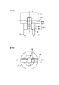
- FIG. 3A is a plan view of the frame as viewed from above.
- 3B is a cross-sectional view taken along line AA in FIG. 3A.
- FIG. 3C is a side view when viewed from the direction B of FIG. 3A.
- Sectional drawing which shows the relationship between the male type
- FIG. 5A is a diagram showing a relationship of forces when the concave upper surface 11 is horizontal.
- FIG. 5B is a diagram showing a relationship of forces when the normal drawn from the contact point between the concave upper surface 11 and the convex part 62-1 passes through a position farther from the axis 9 than the center 33-1 of the rotation axis.
- FIG. 5C shows a case where the normal drawn from the contact point between the concave upper surface 11 and the convex part 62-1 passes through a position closer to the axis 9 than the center 33-1 of the rotating shaft, and no separation force is generated. The figure which shows the relationship of force when.
- FIG. 5C shows a case where the normal drawn from the contact point between the concave upper surface 11 and the convex part 62-1 passes through a position closer to the axis 9 than the center 33-1 of the rotating shaft, and no separation force is generated. The figure which shows the relationship of force when.
- FIG. 5C shows a case where the normal drawn from the contact point between the concave upper surface 11 and the convex part 62-1 passes through a position closer to the axis 9
- 5D shows a case where the normal drawn from the contact point between the concave upper surface 11 and the convex part 62-1 passes through a position closer to the axis 9 than the center 33-1 of the rotation axis, and a separation force is generated.
- FIG. 9A is a side view of the frame 21 of Modification 2 as viewed from the C side in FIG. 8.
- FIG. 9B is a side view of the frame 21 of Modification 2 as viewed from the D side in FIG. 8.
- FIG. 10A is an enlarged cross-sectional view of a rotor frame, a male member portion, and a rotary head portion according to Modification 2;
- FIG. 10B is a diagram showing a force applied to the second male member 40.
- FIG. 10C is a diagram showing a force applied to the male member 23-1.
- FIG. 15A is an enlarged side view of a frame, a male member, and a guide pin of Modification 4.
- FIG. 15B is an enlarged bottom view of the frame, the male member, and the guide pin of Modification 4.
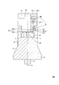
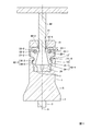
- FIG. 1 is a cross-sectional view showing the internal configuration of the centrifuge of the present invention.
- the rotary shaft 3 whose axis 9 is vertical
- the rotary head 2 attached to the upper part of the rotary shaft 3
- the rotor 20 arranged on the upper part of the rotary head 2, and the upper part of the rotor 20 are shown.
- a covering lid 25 is shown.
- a motor for rotating the rotary shaft 3 and a casing for covering the whole are components of the centrifuge 1.
- the upper side of the rotor 20 is a portion for inserting a sample, and includes a plurality of sample insertion portions 36.
- the rotor 20 also includes rotor holes 28 and 29 into which the rotary head 2 is inserted, a frame 21, male members 23-1 and 23-2, guide pins 24, and the like.
- the rotor hole 28 is a circular hole with a constant diameter
- the rotor hole 29 is a circular hole with a diameter that is smaller toward the inside of the hole.
- two male members are arranged, but one member may be used, or three or more members may be used. The number of male members may be appropriately determined in consideration of the size of the rotor 20 and the like.
- the male mold members 23-1, 23-2 are rotatable around rotation shafts 22-1, 22-2 disposed horizontally inside the rotor hole 28, and their center of gravity is the rotation shafts 22-1, 22-2. 2 below.
- the male members 23-1 and 23-2 have convex portions 62-1 and 62-2 on the opposite side of the axis 9 of the rotary shaft 3 below the center of gravity.
- the male members 23-1 and 23-2 are first attached to the frame 21, and then the frame 21 is attached to the rotor 20 for easy manufacture.
- the rotor 20 also includes through holes 30 and 31 having a circular cross section around the axis 9. Screws (threaded portions) are formed in the through holes 31 formed in the frame 21.
- the rotary head 2 includes a rotor coupling portion 6 and a drive pin 7 at the top.
- the rotor coupling portion 6 has a cylindrical shape centered on the axis 9 of the rotating shaft, and has an annular recess 8 on the inner surface.
- the rotary head 2 has a circular section 4 having a constant diameter and a circular section that fits in the rotor hole 28 and a circular truncated cone section that has a diameter that fits in the rotor hole 29 is increased toward the bottom.
- the lid 25 has a knob 26 and a screw portion 27. By rotating the knob 26, the through hole 31 and the screw portion 27 of the frame 21 are screwed, and the lid 25 is fixed to the rotor 20.
- the guide pin 24 can move only between the drive pins 7, when the rotary head 2 rotates, power is transmitted from the drive pin 7 to the guide pins 24, and the rotor 20 rotates. Even when the rotary head 2 stops, the drive pin 7 limits the movement range of the guide pin 24, so the rotor 20 stops together with the rotary head 2.
- the center of gravity of the male members 23-1, 23-2 is directly below the rotary shafts 22-1, 22-2.
- the male members 23-1 and 23-2 are inside the rotor coupling portion 6, and the convex portions 62-1 and 62-2 of the male members 23-1 and 23-2 are the rotor coupling portion 6. This is opposed to the concave portion 8.
- the convex parts 62-1 and 62-2 move so as to fit into the concave part 8. Then, when a force for separating the rotor 20 from the rotary head 2 is applied when the convex portions 62-1 and 62-2 are fitted in the concave portion 8, the convex portions 62-1 and 62-2 are fitted in the concave portion 8. Force is applied in the direction.
- the normal line of the recess upper surface 11 that is the upper surface of the recesses 62-1 and 62-2 may be formed so as to pass through a position closer to the axis than the center of the rotation axis.
- the rotating shafts 22-1 and 22-2 may be arranged so that the drawn normal line passes through a position closer to the axis 9 than the centers 33-1 and 33-2 of the rotating shaft.
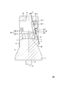
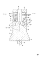
- FIG. 2 is an enlarged cross-sectional view of the rotor frame and the male member and the rotary head
- FIG. 3 is an enlarged view of the rotor frame and the male member
- FIG. 4 is the male when rotating. It is sectional drawing which shows the relationship between a mold member and a rotary head.
- 3A is a plan view of the frame as viewed from above
- FIG. 3B is a cross-sectional view when cut along the line AA
- FIG. 3C is a side view when viewed from the direction B of FIG. 3A.
- 2 and 4 show only the male member 23-1, only one male member may be used as described above, or two male members may be provided as shown in FIGS. Alternatively, three or more may be provided as described above.
- the concave portion 8 includes a concave bottom surface 10 that is recessed from the inner surface of the rotor coupling portion 6, a concave top surface 11 that contacts the convex portion 62-1 when a separation force is generated in the rotor 20, and an uppermost portion of the rotor coupling portion 6. It is comprised by the recessed part cylindrical part 12 located in.
- the convex portion 62-1 contacts the concave bottom surface 10 when the rotor 20 rotates, and the convex portion positioning surface 34-1 determines the posture (position) of the male member 23-1, and the rotor 20 generates a separation force.
- the convex portion contact surface 35-1 that comes into contact with the concave portion upper surface 11 is formed. As shown in FIG. 4, the normal line drawn from the contact portion of the concave upper surface 11 with the convex contact surface 35-1 passes through a position closer to the axis 9 than the center 33-1 of the rotation axis.
- the centrifuge of the present invention has such a structure, it is not necessary to stop the screw when attaching the rotor to the rotary head. Also, it is not necessary to remove the screws when removing the rotor from the rotary head. Furthermore, even when a force that causes a rotor that is not assumed during rotation to be detached from the rotary head is applied, the convex portion and the concave portion are not separated. Therefore, both simple attachment and detachment and reliable fixing can be realized.
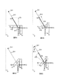
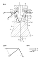
- FIG. 5 is a schematic diagram for explaining this principle.
- the convex portion 62-1 is represented by a circle
- the male member 23-1 is represented by a line.
- 5A shows a case where the concave upper surface 11 is horizontal
- FIG. 5B shows a case where the concave upper surface 11 is horizontal
- FIG. 5B shows that the normal drawn from the contact point between the concave upper surface 11 and the convex 62-1 passes through a position farther from the axis 9 than the center 33-1 of the rotation axis.
- FIG. 5C shows a case where the normal drawn from the contact point between the concave upper surface 11 and the convex part 62-1 passes through a position closer to the axial center 9 than the center 33-1 of the rotating shaft, and the separation force is generated.
- FIG. 5D shows a case where the normal drawn from the contact point between the concave upper surface 11 and the convex part 62-1 passes through a position closer to the axis 9 than the center 33-1 of the rotation axis. It shows when force is generated.
- FIG. 5 shows a force F1 due to gravity, a force F2 due to centrifugal force, and a force F3 received by the convex portion 62-1 due to a force that causes the rotor 20 to be detached among the forces acting on the convex portion 62-1.
- the convex portion 62-1 has a reaction force in which the concave bottom surface 10 and the concave top surface 11 push back the convex portion 62-1, and a male member 23-1 has a force to pull the convex portion 62-1.
- these forces are generated in order to balance F1 to F3, and are not shown in the figure.
- the direction of the force F1 is downward, and the direction of the force F2 is the right direction in the figure. Further, since the male member 23-1 is rotatable around the rotation axis, the direction of the force F3 is the direction of the center 33-1 of the rotation axis. Since the convex portion 62-1 tends to move in the direction of the sum of these forces, it tries to move counterclockwise or clockwise. When trying to move counterclockwise, the convex portion 62-1 tends to fit into the concave portion 8. As a result, the convex portion 62-1 is pressed against the concave top surface 11 or the concave bottom surface 10.
- the reaction force from the concave top surface 11 or the concave bottom surface 10 is also applied as a force acting on the convex portion 62-1, and the force acting on the convex portion 62-1 is balanced.
- the convex portion 62-1 is detached from the concave portion 8, and the rotor 20 may be detached.
- the convex portion 62-1 tries to move so that the total direction of the force F1 and the force F2 coincides with the line of the male member 23-1. Therefore, when the rotational speed is increased and F2 is sufficiently large, the convex portion 62-1 fits into the concave portion 8.
- F2 is 10 times or more F1 at a position 1 cm away from the axis 9.
- the normal line drawn from the contact point between the concave upper surface 11 and the convex part 62-1 passes through a position closer to the axis 9 than the center 33-1 of the rotation axis.
- the convex portion 62-1 is in contact with only the bottom surface 10 of the recess, and there is a gap between the top surface 11 of the recess.
- force F3 when force F3 is applied, the force relationship changes.
- the force F3 is perpendicular to the recess upper surface 11 and the force F31 is parallel to the force F32. If the rotation speed is constant, the force F1 and the force F2 are constant. However, a force F3 that is not expected in an accident in which the rotor 20 comes off is applied. That is, when the force F3 is increased, it can be determined in what direction the upper surface 11 of the concave portion 11 should be oriented by confirming whether or not the force that causes the convex portion 62-1 to fit into the concave portion 8 is applied.
- the force parallel to the concave upper surface 11 is examined.
- the force F3 increases, the force F32 also increases, so that the force with which the convex portion 62-1 attempts to fit into the concave portion 8 becomes weak.
- the force F3 is an unexpected force, it is impossible to design how much force the convex portion 62-1 tries to fit into the concave portion 8 remains. Therefore, there is a risk that force is applied in the direction of disengagement.
- the force for separating the rotor 20 can be converted into a force in the direction in which the convex portion 62-1 fits into the concave portion 8, so Even when a force for separating from the rotary head is applied, the convex portion and the concave portion are not separated.
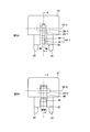
- FIG. 8 is an enlarged cross-sectional view of the rotor frame, the male member portion, and the rotary head portion of the second modification example with the rotary shaft stopped
- FIG. 9 is a diagram showing the frame 21 of the second modification example.
- 10 is an enlarged cross-sectional view of the rotor frame, the male member portion, and the rotary head portion of the modified example 2 with the rotating shaft rotated.
- 9A is a side view of the frame 21 viewed from the C side of FIG. 8
- FIG. 9B is a side view of the frame 21 viewed from the D side of FIG. 10A is an enlarged cross-sectional view of the rotor frame, the male member, and the rotary head, FIG.
- FIG. 10B is a diagram illustrating the force applied to the second male member 40
- FIG. 10C is applied to the male member 23-1. It is a figure which shows force.
- the rotor 20 also includes a second male member 40.
- the second male member 40 is rotatable about a rotating shaft 22-2 disposed horizontally inside the rotor hole 28, and has a center of gravity below the rotating shaft 22-2 and rotates below the center of gravity.
- a second convex portion 41 is provided on the side opposite to the shaft 3.
- the thickness of the male member 23-1 is w / 2 with respect to the thickness w of the second male member 40.
- the second male member 40 When the rotor 20 is disposed on the rotary head 2 with the rotary shaft 3 stopped, the center of gravity of the second male member 40 is directly below the rotary shaft 22-2. At this time, the second male member 40 is inside the rotor coupling portion 6, and the second convex portion 41 of the second male member 40 faces the concave portion 8 of the rotor coupling portion 6.
- the second convex portion 41 moves so as to come into contact with a part of the concave portion (in FIG. 10, the concave portion upper surface 11 and the concave portion boundary line 42 of the concave cylindrical portion 12).
- the male member 23-1 also moves as described in the first embodiment, and the convex portion 62-1 contacts the concave bottom surface 10.
- the male member 23-1 and the second male member 40 are asymmetric, a delicate force imbalance occurs, and a force that the rotor 20 presses somewhere on the rotary head 2 is generated. Since this force acts, the minute gaps between the rotor holes 28 and 29, the cylindrical portion 4 and the truncated cone portion 5 are moved to one side, so that vibration can be reduced.
- the male member 23-1 becomes lighter than the second male member 40. Accordingly, the centrifugal force F1 of the second male member 40 that acts during rotation is greater than the centrifugal force F4 of the male member 23-1.
- the second convex portion 41 and the concave boundary line 42 are in contact is not parallel to the axis 9, the second convex portion 41 is forced from the concave boundary line 42 by the force F 2 (contact) unless friction is considered.
- the force in the normal direction of the surface is The force F2 tries to turn the rotating shaft 22-2 counterclockwise.
- the moments generated by these forces are balanced. Therefore, the total force F3 of the centrifugal force F1 and the force F2 is applied to the rotating shaft 22-2.
- the centrifugal force F4 tries to turn the rotating shaft 22-1 counterclockwise.
- the concave bottom surface 10 is a surface parallel to the axis 9, the convex portion 62-1 receives the force F5 in the direction opposite to the centrifugal force F4.
- the force F5 tries to turn the rotating shaft 22-1 clockwise.
- the moments generated by these forces are balanced. Therefore, the total force F6 of the centrifugal force F4 and the force F5 is applied to the rotating shaft 22-1. That is, the force F3 and the force F6 are applied to the rotor 20, and the rotor 20 is generally pressed in the lower left direction in FIG.
- a more complicated force is applied due to the addition of friction and the like, but in any case, a subtle force generated by making the male member 23-1 and the second male member 40 asymmetrical.
- the vibration is reduced by the unbalance (the force that the second male member 40 receives by the rotation of the rotating shaft 3 and the force that the male member 23-1 receives by the rotation of the rotating shaft 3 are not balanced). It is thought that.
- the rotor 20 is provided with a male member 23-1 and a second male member 40 which are members that are moved by centrifugal force. Therefore, since the degree of unbalance can be adjusted optimally in consideration of the weight and shape of the rotor, vibration can be sufficiently reduced for each type of rotor.
- FIG. 11 is an enlarged cross-sectional view of the rotor frame, the male member, and the rotary head in a state in which the male member does not return to the inside of the rotor coupling portion even when the rotating shaft is stopped.
- FIG. 12 is a male member.
- FIG. 5 is an enlarged cross-sectional view of a rotor frame, a male member portion, and a rotary head portion in a state where the rotor is returned to the inside of the rotor coupling portion.
- the male members 23-1, 23-2 are positioned above the rotary shafts 22-1, 22-2 and when the convex portions 62-1 and 62-2 are fitted in the concave portion 8.
- Protrusions 43-1 and 43-2 that protrude inside the through holes 31 are provided.
- the male members 23-1 and 23-2 may be returned to the inside of the rotor coupling portion 6 as follows. . First, the lid 25 is removed so that the through holes 30 and 31 can be seen. Then, the release shaft 44 whose tip is thin is inserted into the through holes 30 and 31. Since the release shaft 44 has a thin tip and gradually becomes thicker near the handle, the protrusion 43-1 is pushed in the right direction in the figure and the protrusion 43-2 is pushed in the left direction in the figure. Accordingly, if the release shaft 44 is pushed deeply as shown in FIG. 12, the male members 23-1 and 23-2 can be returned to the inside of the rotor coupling portion 6. If a screw is formed in a portion of the release shaft 44 that contacts the through hole 31 and the release shaft 44 is pushed in by using the screw formed in the through hole 31 of the frame 21, the release shaft can be easily pushed. 44 can be pushed in.
- FIG. 13 is an enlarged cross-sectional view of a rotor frame, a male member, a guide pin portion, and a rotary head portion of a fourth modification.
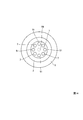
- FIG. 14 is a plan view of the rotary head of the fourth modification as viewed from above. These are the figures which expanded the flame
- 15A is a side view
- FIG. 15B is a bottom view as seen from the lower side. Although only one male member is shown in FIGS. 13 and 15, two or more male members may be provided.
- the guide pin 53 of this modification is longer than the guide pin 24 of the first embodiment.
- the rotary head 2 includes a drive hole 51 into which the guide pin 53 is inserted.
- the rotor 20 of this modification also includes a guide pin 53 that enters the inside of the rotor coupling portion 6 in the vicinity of the male member 23-1.
- the rotary head 2 also includes a drive hole 51 into which the guide pin 53 is inserted.
- the guide pin 53 is limited by the drive pin 7 in the range of the rotation direction with the axis 9 as the rotation axis.
- the tip of the guide pin 53 is inserted into the drive hole 51. Since the position of the guide pin 53 is limited to the drive hole 51, the position of the guide pin 53 is determined.
- the air hole 54 plays a role of releasing the air trapped between the frame 21 and the rotor coupling portion 6 to the outside.
- the air trapped between the frame 21 and the rotor coupling portion 6 causes the rotor 20 not to descend smoothly onto the rotary head 2, causing air to escape. Therefore, it may descend slowly. If it descends slowly in this way, an extra time is spent for the operator, and it is easy to lead to an installation error of the rotor 20. Therefore, such a problem can be solved by providing the air holes 54.
- the present invention can be used for a centrifuge provided with a rotary head attached to the upper part of a rotary shaft whose axis is in the vertical direction and a rotor arranged on the upper part of the rotary head.
Landscapes
- Centrifugal Separators (AREA)
Abstract
Description
次に、ロータ20を離脱させる力を、凸部62-1が凹部8に嵌る方向の力に変換する原理を説明する。図5は、この原理を説明するための模式図である。この図では、凸部62-1を円、雄型部材23-1を線で表している。また、これらの図では、雄型部材23-1の質量は凸部62-1に集中しているものとする。図5Aは凹部上面11が水平の場合を、図5Bは凹部上面11と凸部62-1との接点から引いた法線が回転軸の中心33-1よりも軸心9から遠い位置を通る場合を、図5Cは凹部上面11と凸部62-1との接点から引いた法線が回転軸の中心33-1よりも軸心9に近い位置を通る場合であって、離脱力が発生していないときを、図5Dは凹部上面11と凸部62-1との接点から引いた法線が回転軸の中心33-1よりも軸心9に近い位置を通る場合であって、離脱力が発生しているときを示している。
実施例1では、雄型部材23-1、23-2の重心が回転軸22-1、22-2の真下となったときに、雄型部材23-1、23-2はロータ結合部6の内側にあるように配置されていた。しかし、設計上の都合から、回転シャフト3が停止した状態での重心の位置を回転軸22-1、22-2の真下ではない位置に調整したい場合もある。図6は変形例1のロータのフレームと雄型部材の部分および回転ヘッドの部分を拡大した断面図、図7は変形例1のロータのフレームと雄型部材の部分および回転ヘッドの部分を拡大した断面斜視図である。本変形例では、回転シャフト3が停止した状態での重心の位置を、回転軸22-1、22-2の真下よりも軸心9に近い位置に調整した例を示す。本変形例では、フレーム21に環状の弾性体61が備えられており、雄型部材23-1、23-2を軸心9側に押している。
このように、回転シャフト3が停止した状態での重心の位置を調整できるので、設計自由度を増加させることができる。
小型ロータ(概ね5kg以下)は高速回転(18000~22000回転)するとロータ穴28、29と回転ヘッド2の円柱部分4と円錐台部分5の間にある微小な隙間が原因となって、振動が生じることがある。本変形例では、この課題を解決する。
これまでの実施例、変形例での説明では、回転シャフト3の回転が止まれば雄型部材23-1、23-2は、重力などによってロータ結合部6の内側に戻るので、ロータ20を容易に取り外すことができると説明した。しかし、試料などが漏れてしまい、雄型部材23-1、23-2の周辺に付着してしまうことがある。このような場合に、回転シャフト3の回転が止まっても、雄型部材23-1、23-2がロータ結合部6の内側に戻らないことも想定される。本変形例ではこの課題を解決する。
実施例1の場合、ロータ20と回転ヘッド2との位置関係は、ガイドピン24が駆動ピン7の間に拘束されることによって決まる。しかし、ガイドピン24は駆動ピン7の間では移動可能なので、ロータ20と回転ヘッド2との間にはすべりが生じる。また、ロータ20は回転ヘッド2の上部に配置されているが、ロータ20は、円錐台部分5に支えられている。したがって、前述のすべりによって、特にロータ穴29と円錐台部分5に摩耗が生じることになる。本変形例では、ロータ20と回転ヘッド2との間のすべりをなくす。
3 回転シャフト 4 円柱部分
5 円錐台部分 6 ロータ結合部
7 駆動ピン 8 凹部
9 軸心 10 凹部底面
11 凹部上面 12 凹部円筒部
20 ロータ 21 フレーム
22 回転軸 23 雄型部材
24 ガイドピン 25 蓋
26 つまみ 27 ネジ部
28、29 ロータ穴 30、31 貫通穴
33 回転軸の中心 34 凸部位置決め面
35 凸部接触面 36 試料挿入部
40 第2雄型部材 41 第2凸部
42 凹部境界線 43 突起部
44 解除シャフト 51 駆動穴
53 ガイドピン 54 空気穴
61 弾性体 62 凸部
Claims (8)
- 軸心が鉛直方向である回転シャフトの上部に取り付けられた回転ヘッドと、前記回転ヘッドの上部に配置されるロータとを備えた遠心分離機であって、
前記ロータは、
前記回転ヘッドが挿入されるロータ穴と、
前記ロータ穴の内部に水平に配置された回転軸を中心として回転自在であり、重心が前記回転軸の下方にあり、重心よりも下方の前記回転シャフトの反対側に凸部を有する雄型部材と
を備え、
前記回転ヘッドは、上部に前記回転シャフトの軸心を中心とする円筒状であり、内側面に環状の凹部を有するロータ結合部を備え、
前記回転シャフトが停止した状態で前記ロータが前記回転ヘッドの上に配置されているときには、前記雄型部材は前記ロータ結合部の内側にあり、かつ、前記雄型部材の凸部が前記ロータ結合部の凹部と対向し、
前記回転シャフトの回転によって前記凸部が前記凹部に嵌るように可動し、
前記凸部が前記凹部に嵌っているときに、前記ロータを前記回転ヘッドから離脱させる力が加わった場合に、前記凸部には前記凹部に嵌る方向に力が加わる
ことを特徴とする遠心分離機。 - 軸心が鉛直方向である回転シャフトの上部に取り付けられた回転ヘッドと、前記回転ヘッドの上部に配置されるロータとを備えた遠心分離機であって、
前記ロータは、
前記回転ヘッドが挿入されるロータ穴と、
前記ロータ穴の内部に水平に配置された回転軸を中心として回転自在であり、重心が前記回転軸の下方にあり、重心よりも下方の前記回転シャフトと反対側に凸部を有する雄型部材と
を備え、
前記回転ヘッドは、上部に前記回転シャフトの軸心を中心とする円筒状であり、内側面に環状の凹部を有するロータ結合部を備え、
前記回転シャフトが停止した状態で前記ロータが前記回転ヘッドの上に配置されているときには、前記雄型部材は前記ロータ結合部の内側にあり、かつ、前記雄型部材の凸部が前記ロータ結合部の凹部と対向し、
前記回転シャフトの回転によって前記凸部が前記凹部に嵌るように可動し、
前記凹部の上側の面である凹部上面の法線は、前記回転軸の中心よりも前記軸心に近い位置を通る
ことを特徴とする遠心分離機。 - 請求項1または2記載の遠心分離機であって、
前記ロータは、
前記回転シャフトが停止した状態で前記ロータが前記回転ヘッドの上に配置されているときには、前記雄型部材は前記ロータ結合部の内側にあるように、前記雄型部材を軸心方向に押えるための環状の弾性体も備える
ことを特徴とする遠心分離機。 - 請求項1から3のいずれかに記載の遠心分離機であって、
前記ロータは、前記ロータ穴の内部に水平に配置された回転軸を中心として回転自在であり、重心が前記回転軸の下方にあり、重心よりも下方の前記回転シャフトと反対側に第2凸部を有する第2雄型部材も備え、
前記回転シャフトが停止した状態で前記ロータが前記回転ヘッドの上に配置されているときには、前記第2雄型部材は前記ロータ結合部の内側にあり、かつ、前記第2雄型部材の第2凸部が前記ロータ結合部の凹部と対向し、
前記回転シャフトの回転によって前記第2凸部が前記凹部の一部と接触するように可動し、前記第2雄型部材が前記回転シャフトの回転によって受ける力と、前記雄型部材が前記回転シャフトの回転によって受ける力とはバランスが取れない
ことを特徴とする遠心分離機。 - 請求項1から3のいずれかに記載の遠心分離機であって、
前記ロータは、前記ロータ穴の内部に水平に配置された回転軸を中心として回転自在であり、重心が前記回転軸の下方にあり、重心よりも下方の前記回転シャフトと反対側に第2凸部を有する第2雄型部材も備え、
前記回転シャフトが停止した状態で前記ロータが前記回転ヘッドの上に配置されているときには、前記第2雄型部材は前記ロータ結合部の内側にあり、かつ、前記第2雄型部材の第2凸部が前記ロータ結合部の凹部と対向し、
前記回転シャフトの回転によって前記第2凸部が前記凹部の一部と接触するように可動し、前記凹部の一部が前記第2凸部に前記ロータを前記第2雄型部材側に寄せる力を加える
ことを特徴とする遠心分離機。 - 請求項1から5のいずれかに記載の遠心分離機であって、
前記ロータは、前記軸心を中心とした断面円形の貫通穴も備え、
前記雄型部材は、前記回転軸よりも上方に、前記凸部が前記凹部に嵌った状態のときに前記貫通穴の内側に出る突起部を有している
ことを特徴とする遠心分離機。 - 請求項1から6のいずれかに記載の遠心分離機であって、
前記ロータは、前記雄型部材の近傍に前記ロータ結合部の内側に入るガイドピンも備え、
前記回転ヘッドは、前記ガイドピンが挿入される駆動穴も備えている
ことを特徴とする遠心分離機。 - 軸心が鉛直方向である回転シャフトと、
上部に前記回転シャフトの軸心を中心とする円筒状であり、内側面に環状の凹部を有するロータ結合部を備え、前記回転シャフトの上部に取り付けられた回転ヘッド
を備えた遠心分離機の前記回転ヘッドの上部に配置される遠心分離機用ロータであって、
前記回転ヘッドが挿入されるロータ穴と、
前記ロータ穴の内部に水平に配置された回転軸を中心として回転自在であり、重心が前記回転軸の下方にあり、重心よりも下方の前記回転シャフトと反対側に凸部を有する雄型部材と
を備え、
前記回転シャフトが停止した状態で前記ロータが前記回転ヘッドの上に配置されているときには、前記雄型部材は前記ロータ結合部の内側にあり、かつ、前記雄型部材の凸部が前記ロータ結合部の凹部と対向し、
前記回転シャフトの回転によって前記凸部が前記凹部に嵌るように可動し、
前記凹部の上側の面である凹部上面と前記凸部とが接触するときには、接触面の法線は、前記回転軸の中心よりも前記軸心に近い位置を通る
ことを特徴とする遠心分離機用ロータ。
Priority Applications (2)
| Application Number | Priority Date | Filing Date | Title |
|---|---|---|---|
| KR1020117015003A KR101214104B1 (ko) | 2009-06-30 | 2010-04-08 | 원심분리기, 원심분리기용 로터 |
| CN201080004902.2A CN102292161B (zh) | 2009-06-30 | 2010-04-08 | 离心分离机、离心分离机用转子 |
Applications Claiming Priority (2)
| Application Number | Priority Date | Filing Date | Title |
|---|---|---|---|
| JP2009155610A JP5442337B2 (ja) | 2009-06-30 | 2009-06-30 | 遠心分離機、遠心分離機用ロータ |
| JP2009-155610 | 2009-06-30 |
Publications (1)
| Publication Number | Publication Date |
|---|---|
| WO2011001729A1 true WO2011001729A1 (ja) | 2011-01-06 |
Family
ID=43410813
Family Applications (1)
| Application Number | Title | Priority Date | Filing Date |
|---|---|---|---|
| PCT/JP2010/056380 Ceased WO2011001729A1 (ja) | 2009-06-30 | 2010-04-08 | 遠心分離機、遠心分離機用ロータ |
Country Status (4)
| Country | Link |
|---|---|
| JP (1) | JP5442337B2 (ja) |
| KR (1) | KR101214104B1 (ja) |
| CN (1) | CN102292161B (ja) |
| WO (1) | WO2011001729A1 (ja) |
Cited By (11)
| Publication number | Priority date | Publication date | Assignee | Title |
|---|---|---|---|---|
| WO2012059151A1 (de) * | 2010-11-01 | 2012-05-10 | Sigma Laborzentrifugen Gmbh | Rotorlagerung für eine laborzentrifuge |
| US20130331253A1 (en) * | 2012-06-08 | 2013-12-12 | Thermo Electron Led Gmbh | Centrifuge Drive Head For Releasably Connecting A Driving System To A Rotor Of A Centrifuge, A Set And A Centrifuge Comprising The Drive Head |
| US20140329658A1 (en) * | 2013-05-02 | 2014-11-06 | Afi Centrifuge | Laboratory centrifuge comprising means for the locking in translation of a rotor on a driving motor shaft |
| EP2850982A1 (fr) | 2013-09-20 | 2015-03-25 | Santos | Dispositif d'entrainement d'un outil rotatif pour appareil de traitement alimentaire, et appareil de traitement alimentaire pourvu d'un tel dispositif d'entrainement |
| DE102014008219A1 (de) | 2014-05-28 | 2015-12-03 | Thermo Electron Led Gmbh | Antriebskopf zur lösbaren Verbindung eines Antriebes mit einem Rotor einer Zentrifuge, diesen umfassendes Set und Zentrifuge |
| US20160107171A1 (en) * | 2014-10-21 | 2016-04-21 | Sigma Laborzentrifugen Gmbh | Coupling Device for a Laboratory Centrifuge Actuated by Centrifugal Force |
| WO2019238711A1 (de) * | 2018-06-14 | 2019-12-19 | Andreas Hettich Gmbh & Co. Kg | Zentrifuge |
| EP3669992A1 (de) * | 2018-12-18 | 2020-06-24 | Eppendorf AG | Verbindungskonstruktion |
| EP3669993A1 (de) * | 2018-12-18 | 2020-06-24 | Eppendorf AG | Verbindungskonstruktion |
| US11731144B2 (en) * | 2017-12-20 | 2023-08-22 | Eppendorf Se | Centrifuge rotor with locking levers providing visual indication of cover closure |
| EP4487961A1 (de) | 2023-07-04 | 2025-01-08 | Sigma Laborzentrifugen GmbH | Zentrifuge, rotor für eine zentrifuge und antriebskopf für eine zentrifuge |
Families Citing this family (6)
| Publication number | Priority date | Publication date | Assignee | Title |
|---|---|---|---|---|
| FR2951964B1 (fr) * | 2009-11-04 | 2012-04-06 | Bms Internat | Centrifugeuse comprenant des moyens d'indication visuelle et/ou tactile du montage correct du rotor sur l'arbre d'entrainement, et rotor correspondant |
| JP6228895B2 (ja) * | 2014-06-16 | 2017-11-08 | 株式会社久保田製作所 | 遠心分離機とロータ体 |
| JP6192860B1 (ja) * | 2016-07-13 | 2017-09-06 | 株式会社久保田製作所 | ロータの取付構造及び遠心分離機 |
| CN111298923B (zh) * | 2018-12-11 | 2021-11-30 | 中国食品药品检定研究院 | 破碎离心一体装置 |
| CN109939843B (zh) * | 2019-05-05 | 2023-09-29 | 中国工程物理研究院总体工程研究所 | 一种高加速度离心机用电机联锁定位装置 |
| EP4561755A1 (en) * | 2022-07-28 | 2025-06-04 | Fiberlite Centrifuge LLC | Interlocking cones system for attaching a rotor |
Citations (5)
| Publication number | Priority date | Publication date | Assignee | Title |
|---|---|---|---|---|
| JPS4218399Y1 (ja) * | 1964-04-28 | 1967-10-24 | ||
| JPH0664737U (ja) * | 1993-02-26 | 1994-09-13 | 日立工機株式会社 | 回転体の係合機構 |
| JPH11197549A (ja) * | 1997-10-23 | 1999-07-27 | Jouan Sa | 脱着可能なロータを有する遠心分離機と、ロータの軸方向を駆動ヘッドに固定する装置と、遠心分離機用ロータ |
| JP2000107643A (ja) * | 1998-09-30 | 2000-04-18 | Hitachi Koki Co Ltd | 遠心分離機用ロータの着脱機構 |
| JP2006159005A (ja) * | 2004-12-02 | 2006-06-22 | Hitachi Koki Co Ltd | 遠心機 |
Family Cites Families (5)
| Publication number | Priority date | Publication date | Assignee | Title |
|---|---|---|---|---|
| JPH0218399Y2 (ja) * | 1985-05-14 | 1990-05-23 | ||
| US5562554A (en) * | 1992-10-09 | 1996-10-08 | E. I. Du Pont De Nemours And Company | Centrifuge rotor having a fused web |
| GB2388563B (en) * | 2002-05-17 | 2004-05-19 | Hitachi Koki Kk | Bio cell cleaning centrifuge having bio cell cleaning rotor provided with cleaning liquid distributor |
| DE202005007162U1 (de) * | 2005-05-02 | 2006-09-21 | Hengst Gmbh & Co.Kg | Rotor für eine Zentrifuge |
| DE102006020467A1 (de) * | 2006-04-28 | 2007-10-31 | Westfalia Separator Ag | Separator mit Direktantrieb |
-
2009
- 2009-06-30 JP JP2009155610A patent/JP5442337B2/ja active Active
-
2010
- 2010-04-08 KR KR1020117015003A patent/KR101214104B1/ko active Active
- 2010-04-08 CN CN201080004902.2A patent/CN102292161B/zh active Active
- 2010-04-08 WO PCT/JP2010/056380 patent/WO2011001729A1/ja not_active Ceased
Patent Citations (5)
| Publication number | Priority date | Publication date | Assignee | Title |
|---|---|---|---|---|
| JPS4218399Y1 (ja) * | 1964-04-28 | 1967-10-24 | ||
| JPH0664737U (ja) * | 1993-02-26 | 1994-09-13 | 日立工機株式会社 | 回転体の係合機構 |
| JPH11197549A (ja) * | 1997-10-23 | 1999-07-27 | Jouan Sa | 脱着可能なロータを有する遠心分離機と、ロータの軸方向を駆動ヘッドに固定する装置と、遠心分離機用ロータ |
| JP2000107643A (ja) * | 1998-09-30 | 2000-04-18 | Hitachi Koki Co Ltd | 遠心分離機用ロータの着脱機構 |
| JP2006159005A (ja) * | 2004-12-02 | 2006-06-22 | Hitachi Koki Co Ltd | 遠心機 |
Cited By (33)
| Publication number | Priority date | Publication date | Assignee | Title |
|---|---|---|---|---|
| US8852070B2 (en) | 2010-11-01 | 2014-10-07 | Sigma Laborzentrifugen Gmbh | Locking system for axially securing a rotor onto a rotatably mounted shaft |
| WO2012059151A1 (de) * | 2010-11-01 | 2012-05-10 | Sigma Laborzentrifugen Gmbh | Rotorlagerung für eine laborzentrifuge |
| DE102012011531B4 (de) * | 2012-06-08 | 2016-11-10 | Thermo Electron Led Gmbh | Set aus Antriebskopf und Nabe zur lösbaren Verbindung eines Antriebes mit einem Rotor einer Zentrifuge für einen weiten Drehzahlbereich |
| US20130331253A1 (en) * | 2012-06-08 | 2013-12-12 | Thermo Electron Led Gmbh | Centrifuge Drive Head For Releasably Connecting A Driving System To A Rotor Of A Centrifuge, A Set And A Centrifuge Comprising The Drive Head |
| DE102012011531A1 (de) * | 2012-06-08 | 2013-12-12 | Thermo Electron Led Gmbh | Antriebskopf zur lösbaren Verbindung eines Antriebes mit einem Rotor einer Zentrifuge für einen weiten Drehzahlbereich |
| US9718067B2 (en) | 2012-06-08 | 2017-08-01 | Thermo Electron Led Gmbh | Centrifuge drive head for releasably connecting a driving system to a rotor of a centrifuge, a set and a centrifuge comprising the drive head |
| US20140329658A1 (en) * | 2013-05-02 | 2014-11-06 | Afi Centrifuge | Laboratory centrifuge comprising means for the locking in translation of a rotor on a driving motor shaft |
| US9539588B2 (en) * | 2013-05-02 | 2017-01-10 | Afi Centrifuge | Laboratory centrifuge with locking system for locking in translation of rotor on driving motor shaft |
| EP2850982A1 (fr) | 2013-09-20 | 2015-03-25 | Santos | Dispositif d'entrainement d'un outil rotatif pour appareil de traitement alimentaire, et appareil de traitement alimentaire pourvu d'un tel dispositif d'entrainement |
| FR3010886A1 (fr) * | 2013-09-20 | 2015-03-27 | Santos | Dispositif d'entrainement d'un outil rotatif pour appareil de traitement alimentaire, et appareil de traitement alimentaire pourvu d'un tel dispositif d'entrainement |
| US9551381B2 (en) | 2013-09-20 | 2017-01-24 | Santos | Device for driving a rotary tool for a food processing appliance and food processing appliance provided with such a driving device |
| JP2015231618A (ja) * | 2014-05-28 | 2015-12-24 | サーモ エレクトロン エルエーデー ゲーエムベーハー | 遠心分離機の駆動部とロータとを着脱可能に接続するドライブヘッド、ドライブヘッドを含むキット、及び遠心分離機 |
| CN105289858A (zh) * | 2014-05-28 | 2016-02-03 | 热电子Led有限公司 | 驱动头、包括该驱动头的套件、以及离心机 |
| DE102014008219A1 (de) | 2014-05-28 | 2015-12-03 | Thermo Electron Led Gmbh | Antriebskopf zur lösbaren Verbindung eines Antriebes mit einem Rotor einer Zentrifuge, diesen umfassendes Set und Zentrifuge |
| DE102014008219B4 (de) | 2014-05-28 | 2018-08-02 | Thermo Electron Led Gmbh | Antriebskopf zur lösbaren Verbindung eines Antriebes mit einem Rotor einer Zentrifuge, diesen umfassendes Set und Zentrifuge |
| US9452436B2 (en) | 2014-05-28 | 2016-09-27 | Thermo Electron Led Gmbh | Drive head for detachable connection of a drive with a rotor of a centrifuge, kit comprising the drive head, and centrifuge |
| EP3012027A1 (de) | 2014-10-21 | 2016-04-27 | Sigma Laborzentrifugen GmbH | Zentrifugalkraftbetätigte Kupplungseinrichtung für eine Laborzentrifuge |
| US20160107171A1 (en) * | 2014-10-21 | 2016-04-21 | Sigma Laborzentrifugen Gmbh | Coupling Device for a Laboratory Centrifuge Actuated by Centrifugal Force |
| US9782783B2 (en) * | 2014-10-21 | 2017-10-10 | Sigma Laborzentrifugen Gmbh | Coupling device for a laboratory centrifuge actuated by centrifugal force |
| US11731144B2 (en) * | 2017-12-20 | 2023-08-22 | Eppendorf Se | Centrifuge rotor with locking levers providing visual indication of cover closure |
| CN112313011A (zh) * | 2018-06-14 | 2021-02-02 | 安德烈斯黑蒂希股份有限公司 | 离心机 |
| WO2019238711A1 (de) * | 2018-06-14 | 2019-12-19 | Andreas Hettich Gmbh & Co. Kg | Zentrifuge |
| US11986842B2 (en) | 2018-06-14 | 2024-05-21 | Andreas Hettich Gmbh & Co. Kg | Centrifuge |
| WO2020127104A1 (de) * | 2018-12-18 | 2020-06-25 | Eppendorf Ag | Verbindungskonstruktion |
| WO2020127121A1 (de) * | 2018-12-18 | 2020-06-25 | Eppendorf Ag | Verbindungskonstruktion |
| US20220040709A1 (en) * | 2018-12-18 | 2022-02-10 | Eppendorf Ag | Connection construction |
| JP2022514582A (ja) * | 2018-12-18 | 2022-02-14 | エッペンドルフ エスイー | 接続構造 |
| JP2022514749A (ja) * | 2018-12-18 | 2022-02-15 | エッペンドルフ エスイー | 接続構造 |
| JP7250140B2 (ja) | 2018-12-18 | 2023-03-31 | エッペンドルフ エスイー | 接続構造 |
| JP7270043B2 (ja) | 2018-12-18 | 2023-05-09 | エッペンドルフ エスイー | 接続構造 |
| EP3669993A1 (de) * | 2018-12-18 | 2020-06-24 | Eppendorf AG | Verbindungskonstruktion |
| EP3669992A1 (de) * | 2018-12-18 | 2020-06-24 | Eppendorf AG | Verbindungskonstruktion |
| EP4487961A1 (de) | 2023-07-04 | 2025-01-08 | Sigma Laborzentrifugen GmbH | Zentrifuge, rotor für eine zentrifuge und antriebskopf für eine zentrifuge |
Also Published As
| Publication number | Publication date |
|---|---|
| KR101214104B1 (ko) | 2012-12-20 |
| JP5442337B2 (ja) | 2014-03-12 |
| CN102292161A (zh) | 2011-12-21 |
| CN102292161B (zh) | 2013-08-07 |
| KR20110091793A (ko) | 2011-08-12 |
| JP2011011118A (ja) | 2011-01-20 |
Similar Documents
| Publication | Publication Date | Title |
|---|---|---|
| JP5442337B2 (ja) | 遠心分離機、遠心分離機用ロータ | |
| CN104025429B (zh) | 飞轮组件 | |
| US9718067B2 (en) | Centrifuge drive head for releasably connecting a driving system to a rotor of a centrifuge, a set and a centrifuge comprising the drive head | |
| US20130237399A1 (en) | Centrifuge comprising visual and/or tactile indicator for indicating the accurate mounting of the rotor on the drive shaft, and corresponding rotor | |
| JP2018500507A (ja) | ロック機構と、ロック機構を有するプロペラおよび航空機 | |
| TW200916196A (en) | Centrifuge | |
| CN205770110U (zh) | 无人机电池舱盖结构及无人机 | |
| JP2012505494A (ja) | 電池パックを固定するシステム及び関連する組付/分解の自動化方法 | |
| WO2016204175A1 (ja) | 遠心分離機のスイング型ロータ用バケット | |
| JP3861476B2 (ja) | 遠心分離機 | |
| JP2021506577A (ja) | 遠心機ロータ | |
| JP5199186B2 (ja) | 取付機構、特に血液を分離する遠心分離機用の取付機構 | |
| EP0114835B1 (en) | Ultracentrifuge rotor with breakaway base | |
| JP2010042398A5 (ja) | ||
| CN110902368B (zh) | 抓持机构以及组装装置 | |
| JP6192860B1 (ja) | ロータの取付構造及び遠心分離機 | |
| KR101441446B1 (ko) | 회전 안정성 및 소음 방지 기능을 갖는 버 고정모듈 및 이를 구비한 치과용 핸드피스 | |
| US20250387793A1 (en) | Radial locking system for attaching a rotor | |
| EP4234091B1 (en) | Locking mechanism for a lid of a rotor of a centrifuge and centrifuge rotor | |
| JP5006833B2 (ja) | 遠心分離機用ロータ | |
| CN206218220U (zh) | 锁定机构、螺旋桨、电机、动力系统组件及飞行器 | |
| CN216105782U (zh) | 一种用于免爬器带限速功能的分体式防坠落装置 | |
| US20260021494A1 (en) | Rotational locking system for attaching a rotor | |
| JP2007319579A (ja) | 洗濯機 | |
| JP3755768B2 (ja) | 遠心分離機用スイングロータ |
Legal Events
| Date | Code | Title | Description |
|---|---|---|---|
| WWE | Wipo information: entry into national phase |
Ref document number: 201080004902.2 Country of ref document: CN |
|
| 121 | Ep: the epo has been informed by wipo that ep was designated in this application |
Ref document number: 10793900 Country of ref document: EP Kind code of ref document: A1 |
|
| ENP | Entry into the national phase |
Ref document number: 20117015003 Country of ref document: KR Kind code of ref document: A |
|
| NENP | Non-entry into the national phase |
Ref country code: DE |
|
| 122 | Ep: pct application non-entry in european phase |
Ref document number: 10793900 Country of ref document: EP Kind code of ref document: A1 |