WO2011002017A1 - フライホイールエネルギー貯蔵装置 - Google Patents
フライホイールエネルギー貯蔵装置 Download PDFInfo
- Publication number
- WO2011002017A1 WO2011002017A1 PCT/JP2010/061134 JP2010061134W WO2011002017A1 WO 2011002017 A1 WO2011002017 A1 WO 2011002017A1 JP 2010061134 W JP2010061134 W JP 2010061134W WO 2011002017 A1 WO2011002017 A1 WO 2011002017A1
- Authority
- WO
- WIPO (PCT)
- Prior art keywords
- flywheel
- energy storage
- storage device
- rotating shaft
- superconducting
- Prior art date
- Legal status (The legal status is an assumption and is not a legal conclusion. Google has not performed a legal analysis and makes no representation as to the accuracy of the status listed.)
- Ceased
Links
Images


Classifications
-
- F—MECHANICAL ENGINEERING; LIGHTING; HEATING; WEAPONS; BLASTING
- F03—MACHINES OR ENGINES FOR LIQUIDS; WIND, SPRING, OR WEIGHT MOTORS; PRODUCING MECHANICAL POWER OR A REACTIVE PROPULSIVE THRUST, NOT OTHERWISE PROVIDED FOR
- F03G—SPRING, WEIGHT, INERTIA OR LIKE MOTORS; MECHANICAL-POWER PRODUCING DEVICES OR MECHANISMS, NOT OTHERWISE PROVIDED FOR OR USING ENERGY SOURCES NOT OTHERWISE PROVIDED FOR
- F03G3/00—Other motors, e.g. gravity or inertia motors
- F03G3/08—Other motors, e.g. gravity or inertia motors using flywheels
-
- F—MECHANICAL ENGINEERING; LIGHTING; HEATING; WEAPONS; BLASTING
- F16—ENGINEERING ELEMENTS AND UNITS; GENERAL MEASURES FOR PRODUCING AND MAINTAINING EFFECTIVE FUNCTIONING OF MACHINES OR INSTALLATIONS; THERMAL INSULATION IN GENERAL
- F16C—SHAFTS; FLEXIBLE SHAFTS; ELEMENTS OR CRANKSHAFT MECHANISMS; ROTARY BODIES OTHER THAN GEARING ELEMENTS; BEARINGS
- F16C32/00—Bearings not otherwise provided for
- F16C32/04—Bearings not otherwise provided for using magnetic or electric supporting means
- F16C32/0406—Magnetic bearings
- F16C32/0408—Passive magnetic bearings
- F16C32/0436—Passive magnetic bearings with a conductor on one part movable with respect to a magnetic field, e.g. a body of copper on one part and a permanent magnet on the other part
- F16C32/0438—Passive magnetic bearings with a conductor on one part movable with respect to a magnetic field, e.g. a body of copper on one part and a permanent magnet on the other part with a superconducting body, e.g. a body made of high temperature superconducting material such as YBaCuO
-
- F—MECHANICAL ENGINEERING; LIGHTING; HEATING; WEAPONS; BLASTING
- F16—ENGINEERING ELEMENTS AND UNITS; GENERAL MEASURES FOR PRODUCING AND MAINTAINING EFFECTIVE FUNCTIONING OF MACHINES OR INSTALLATIONS; THERMAL INSULATION IN GENERAL
- F16C—SHAFTS; FLEXIBLE SHAFTS; ELEMENTS OR CRANKSHAFT MECHANISMS; ROTARY BODIES OTHER THAN GEARING ELEMENTS; BEARINGS
- F16C2361/00—Apparatus or articles in engineering in general
- F16C2361/55—Flywheel systems
Definitions
- the present invention relates to a flywheel energy storage device in which a rotating shaft connected to a flywheel is rotatably supported by a superconducting thrust bearing.
- flywheel energy storage devices have been developed that temporarily store energy so that it can be taken out when necessary.
- This flywheel energy storage device has a configuration in which a rotating shaft is rotatably supported by a superconducting thrust bearing and a flywheel is connected to the rotating shaft (see, for example, Patent Document 1).
- the rotating shaft may bend due to the centrifugal force of the flywheel, which may cause rotation loss.
- the flywheel energy storage device in which the rotary shaft connected to the flywheel is rotatably supported by the superconducting thrust bearing, the flywheel is connected to the middle portion of the rotary shaft,
- the rotary shaft is supported by a superconducting thrust bearing in a rotatable manner before and after the wheel, and the flywheel is supported by a superconducting thrust bearing in a rotatable manner.
- the flywheel arranges the torus at a position eccentric from the rotation center of the rotation shaft, and Spokes arranged at equal intervals in the circumferential direction are interposed between the rotating shaft and the spokes are slidably connected to the rotating shaft in the radial direction, while the spoke is circumferentially connected to the torus. It was decided to connect so that it could be moved and locked toward.
- a guide rail is formed on the annular body and a stopper is formed at a predetermined position of the guide rail, while the guide rail is formed on the spoke.
- a wheel that slides along the guide rail is provided, and the spoke can move in the circumferential direction by sliding along the guide rail, and the spoke can be locked by contacting the wheel and the stopper. .
- a flywheel energy storage device in which a rotary shaft to which a flywheel is connected is rotatably supported by a superconducting thrust bearing, the flywheel is connected in the middle of the rotary shaft, and is rotated before and after the flywheel. Since the shaft is supported rotatably by the superconducting thrust bearing, and the flywheel is supported rotatably by the superconducting thrust bearing, the rotating shaft is bent due to the centrifugal force of the flywheel. This can prevent the rotation loss, and can increase the energy storage time and storage amount of the flywheel energy storage device.
- the torus is arranged at a position eccentric from the rotation center of the rotating shaft, and the spokes are arranged at equal intervals in the circumferential direction between the torus and the rotating shaft.
- the spoke is connected to the rotating shaft so as to be slidable in the radial direction, while the spoke is connected to the annular body so as to be movable and lockable in the circumferential direction.
- the rotational shaft and the flywheel can be linked and connected without bending the rotational shaft while absorbing the rotational difference between the shaft and the flywheel.
- the guide rail is formed on the torus and the stopper is formed at a predetermined position of the guide rail, while the spoke is provided with a wheel that slides along the guide rail, and the wheel slides along the guide rail. Therefore, the spoke can be moved in the circumferential direction, and the spoke can be locked by contacting the wheel and the stopper. Therefore, the interlock mechanism of the rotating shaft and the flywheel can be easily assembled. It can be a structure.
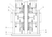
- FIG. 1 is a front view showing a flywheel energy storage device according to Embodiment 1.
- FIG. FIG. 1 is a front view showing a flywheel energy storage device according to Embodiment 1.
- FIG. The right side view. The center end view. The front side end view.
- FIG. FIG. 1 is a front view showing a flywheel energy storage device according to Embodiment 1.
- the front side end view which shows the flywheel energy storage apparatus which concerns on Example 2.
- the flywheel energy storage device 1 can freely rotate a rotating shaft 3 extending forward and backward in a casing 2 via a pair of front and rear superconducting thrust bearings 4 and 4.
- the flywheel 5 is connected to the center of the rotary shaft 3, and the flywheel 5 is rotatably attached to the casing 2 via a superconducting thrust bearing 6.
- the casing 2 is provided with a pair of front and rear plate-like support bases 8.9 on the left side of the front and rear ends of the rectangular plate-like base 7 to support the superconducting thrust bearings 4 and 4 with the support bases 8 and 9.
- a plate-like support base 10 is erected at the center of the base 7 and the superconducting thrust bearing 6 is supported by the support base 10.
- the rotary shaft 3 is formed in a hollow cylindrical shape and is rotatably supported by superconducting thrust bearings 4 and 4 attached to the casing 2 at a front position and a rear position from the flywheel 5.
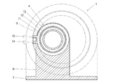
- the superconducting thrust bearings 4 and 4 are provided with an annular rotor-side permanent magnet 11 attached to the outer peripheral portion of the rotary shaft 3, while a hollow annular case 12 is attached to the upper part of the support bases 8 and 9 of the casing 2.
- a plurality of superconductors 13 on the stator side made of a superconducting material are embedded in the inner peripheral surface of the twelve inner circumferential surfaces at intervals in the circumferential direction.
- the case 12 and the superconductor 13 are formed separately, but may be formed integrally.
- Superconducting thrust bearings 4 and 4 are formed with an inlet 14 and an outlet 15 communicating with the hollow portion on the left side of case 12, and a refrigerant such as liquid nitrogen for cooling superconductor 13. Is injected into the hollow portion from the inlet 14 of the case 12, and the refrigerant can be discharged from the hollow portion of the case 12 to the outlet 15.
- a refrigerant such as liquid nitrogen for cooling superconductor 13.
- the superconducting thrust bearings 4 and 4 cause the superconducting phenomenon by the action of the refrigerant filled in the hollow portion of the case 12, and the rotating shaft 3 rotates without moving in the axial direction by the superconducting pinning effect phenomenon. I support it freely.
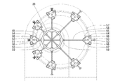
- the flywheel 5 rotatably supports an annular ring body 16 by a superconducting thrust bearing 6 at a position eccentric from the rotation center of the rotary shaft 3, and the outer side (front side and rear side) of the ring body 16. And a pair of front and rear spokes 17 disposed at equal intervals in the circumferential direction.
- the annular body 16 has annular guide bodies 18 attached to the front and rear surfaces thereof, groove-shaped guide rails 19 and 20 are formed on the inner and outer peripheral surfaces of each guide body 18, and the outer guide rail 20 has 2
- the stoppers 21 are formed at intervals in the circumferential direction. The number of stoppers 21 may be one or more.
- the spoke 17 is attached to the rotary shaft 3 with a pair of left and right rods 22 slidably in the radial direction via bearings 23, and a weight 24 is attached to one end of the rod 22 via a damper 25.
- the rod 26 is slidably mounted along the rod 22, and a weight 26 is slidably mounted along the rod 22 at the other end of the rod 22, and the rods 24 and 26 are extended in parallel with the rotary shaft 3.
- a base end portion of the support body 27 is attached, and a substantially triangular plate-like frame 28 is attached to the front end portion of the support body 27 so as to be rotatable in a direction orthogonal to the rotation shaft 3, and an inner guide rail is provided on the inner peripheral side of the frame 28.
- Wheels 29 that slide along 19 are rotatably attached, and wheels 30 and 30 that slide along the outer guide rail 20 are rotatably attached to the outer peripheral side of the frame 28.
- the flywheel 5 slidably connects the spoke 17 to the rotary shaft 3 in the radial direction, and the wheels 29 and 30 slide along the guide rails 19 and 20 so that the spoke 17 is circumferentially connected.
- the spokes 17 can be locked when the wheels 30 and the stoppers 21 come into contact with each other, and the spokes 17 are connected to the annular body 16 so as to be movable and lockable in the circumferential direction. ing.
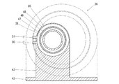
- the superconducting thrust bearing 6 has an annular rotor-side permanent magnet 31 attached to the outer periphery of an annular body 16, while a hollow annular case 32 is attached to the upper part of the support 10 of the casing 2.
- a plurality of stator-side superconductors 33 are embedded in the circumferential surface at intervals in the circumferential direction.
- the annular body 16 and the permanent magnet 31 are formed separately, but may be formed integrally.
- the case 32 and the superconductor 33 may be formed integrally.
- the superconducting thrust bearing 6 is formed with an inlet 34 and an outlet 35 communicating with the hollow portion on the left side of the case 32, and a refrigerant such as liquid nitrogen for cooling the superconductor 33 is provided in the case.
- the refrigerant can be injected into the hollow portion from the 32 injection ports 34, and the refrigerant can be discharged from the hollow portion of the case 32 to the discharge port 35.
- the superconducting thrust bearing 6 causes a superconducting phenomenon by the action of the refrigerant filled in the hollow portion of the case 32, and can rotate freely without moving the flywheel 5 in the axial direction by the superconducting pinning effect phenomenon. To support.
- the flywheel 5 is connected to the middle part (central part) of the rotary shaft 3, and the rotary shaft 3 is superconducted before and after the flywheel 5.
- the thrust bearings 4 and 4 are rotatably supported, and the flywheel 5 is rotatably supported by the superconducting thrust bearing 6.
- the torus 16 is disposed at a position eccentric from the rotation center of the rotating shaft 3, and the outer side (front side and rear side) of the torus 16 and the rotating shaft 3 are arranged.
- a pair of front and rear spokes 17 arranged at equal intervals in the circumferential direction is interposed between the spokes 17 and the spokes 17 connected to the rotating body 3 while being slidable in the radial direction. 17 is connected so as to be movable and lockable in the circumferential direction.
- the guide rail 20 is formed on the torus 16 and the stopper 21 is formed at a predetermined position of the guide rail 20, while the wheel 30 is slid along the guide rail 20 on the spoke 17.
- the spokes 17 can be moved in the circumferential direction by sliding the wheels 30 along the guide rails 20, and the spokes 17 can be locked by contacting the wheels 30 and the stoppers 21.
- the flywheel energy storage device 36 is capable of rotating a rotating shaft 38 extending forward and backward in a casing 37 via a pair of front and rear superconducting thrust bearings 39 and 39.
- the flywheel 40 is connected to the central portion of the rotary shaft 38, and the flywheel 40 is rotatably attached to the casing 37 via a pair of front and rear superconductive thrust bearings 41 and 41.
- the casing 37 is provided with a pair of front and rear plate-like support bases 43 and 44 on the left side of the front and rear ends of the rectangular plate-like base 42, and supports the superconducting thrust bearings 39 and 39 with the support bases 43 and 44.
- a pair of front and rear plate-like support bases 45 and 46 are erected at a central portion of the base 42 with a space in the front and rear directions, and the superconducting thrust bearings 41 and 41 are supported by the support bases 45 and 46.
- the rotary shaft 38 is formed in a hollow cylindrical shape and is rotatably supported by superconducting thrust bearings 39 and 39 attached to the casing 37 at a front position and a rear position from the flywheel 40.
- the superconducting thrust bearings 39 and 39 are provided with a ring-shaped rotor-side permanent magnet 47 attached to the outer peripheral portion of the rotary shaft 38, while a hollow annular case 48 is attached to the upper part of the support bases 43 and 44 of the casing 37.
- a plurality of stator-side superconductors 49 made of a superconducting material are embedded in the inner peripheral surface of the 48 at intervals in the circumferential direction.
- the case 48 and the superconductor 49 are formed separately, but may be formed integrally.
- the superconducting thrust bearings 39, 39 are formed with an inlet 50 and an outlet 51 communicating with the hollow portion on the left side of the case 48, and a refrigerant such as liquid nitrogen for cooling the superconductor 49. Is injected into the hollow portion from the injection port 50 of the case 48, and the refrigerant can be discharged from the hollow portion of the case 48 to the discharge port 51.
- a refrigerant such as liquid nitrogen for cooling the superconductor 49.
- the superconducting thrust bearings 39, 39 cause a superconducting phenomenon by the action of the refrigerant filled in the hollow portion of the case 48, and the rotating shaft 38 rotates without moving in the axial direction due to the superconducting pinning effect phenomenon. I support it freely.
- the flywheel 40 rotatably supports a pair of front and rear annular rings 52 and 52 by superconducting thrust bearings 41 and 41 at a position eccentric from the rotation center of the rotation shaft 38, and a pair of front and rear circles.
- the pair of front and rear toric bodies 52, 52 has an annular guide body 54 attached to the inner side surfaces (the rear surface of the front torus 52 and the front surface of the rear toroid 52).
- Groove-shaped guide rails 55 and 56 are formed on the inner and outer peripheral surfaces, and two stoppers 57 are formed on the outer guide rail 56 at intervals in the circumferential direction.
- the number of stoppers 21 may be one or more.
- the spoke 53 has a rod body 58 attached to the rotary shaft 38 through a bearing 59 so as to be slidable in the radial direction, and a rectangular box-shaped weight 60 extending forward and backward at one end portion of the rod body 58.
- a rectangular box-shaped weight 62 extending back and forth is attached to the other end of the rod body 58 in a slidable manner along the rod body 58.
- base ends of rod-like supports 63, 63 extending in parallel with the rotary shaft 38 are attached, and a substantially triangular plate frame 64 is attached to the tip of each support 63.
- the wheels 65 that slide along the inner guide rails 55 are rotatably attached to the inner peripheral side of each frame 64, and the outer guides are attached to the outer peripheral side of the respective frames 64. Wheels 66 and 66 that slide along the rail 56 are rotatably mounted.
- the flywheel 40 slidably connects the spoke 53 to the rotary shaft 38 in the radial direction, and the wheels 65 and 66 slide along the guide rails 55 and 56 so that the spoke 53 is circumferentially connected.
- the spokes 53 can be locked by the wheels 66 and the stoppers 57 coming into contact with each other, and the spokes 53 can be moved in the circumferential direction and engaged with the pair of front and rear toroids 52, 52. Connection is possible.
- the superconducting thrust bearings 41, 41 are attached to the outer periphery of the annular members 52, 52 by attaching an annular rotor-side permanent magnet 67, while the hollow annular case 68, A plurality of superconductors 69 on the stator side are embedded in the inner peripheral surface of each case 68 at intervals in the circumferential direction.
- the annular body 52 and the permanent magnet 67 are formed separately, but may be formed integrally.
- the case 68 and the superconductor 69 may be formed integrally.
- Superconducting thrust bearings 41 and 41 are formed with an inlet 70 and an outlet 71 communicating with the hollow portion on the left side of case 68, and a refrigerant such as liquid nitrogen for cooling superconductor 69. Is injected into the hollow portion from the inlet 70 of the case 68, and the refrigerant can be discharged from the hollow portion of the case 68 to the outlet 71.
- a refrigerant such as liquid nitrogen for cooling superconductor 69.
- the superconducting thrust bearings 41 and 41 cause the superconducting phenomenon by the action of the refrigerant filled in the hollow portion of the case 68, and the flywheel 40 rotates without moving in the axial direction due to the superconducting pinning effect phenomenon. I support it freely.
- the flywheel 40 is connected to the middle part (central part) of the rotary shaft 38 and the rotary shaft 38 is superconducted before and after the flywheel 40.
- the thrust bearings 39 and 39 are rotatably supported, and the flywheel 40 is rotatably supported by a pair of front and rear superconducting thrust bearings 41 and 41.
- a pair of front and rear toric bodies 52, 52 are arranged at a position eccentric from the rotation center of the rotating shaft 38, and the inner side of each toroidal body 52 ( Spokes 53 arranged at equal intervals in the circumferential direction are interposed between the rotating shaft 38 between the rear side of the front annular body 52 and the front side of the rear annular body 52) and the rotating shaft 38. While the spokes 53 are slidably connected in the radial direction, the spokes 53 are connected to the respective annular members 52 so as to be movable and lockable in the circumferential direction.
- a guide rail 56 is formed on each annular body 52 and a stopper 57 is formed at a predetermined position of the guide rail 56, while a wheel that slides along the guide rail 56 on the spoke 53.
- the spokes 53 can be moved in the circumferential direction by the wheels 66 sliding along the guide rails 56, and the spokes 53 can be locked by the wheels 66 and the stoppers 57 coming into contact with each other.
- the flywheel energy storage devices 1 and 36 according to the first and second embodiments are configured as described above, and the centrifugal force that acts on the flywheels 5 and 40 by rotating the rotary shafts 3 and 38 is configured.
- the rotating shafts 3,38 are continuously rotated for a long time using force, thereby storing energy, and then removing the energy from the rotating shafts 3,38 when necessary.
- the mechanism for rotating the rotary shafts 3 and 38 is not particularly limited, and a motor connected via a power interrupting mechanism such as a clutch may be used, or the rotary shafts 3 and 38 may be driven by vibration or wind power. You may make it rotate using etc.
- the mechanism for taking out energy from the rotary shafts 3, 38 is not particularly limited, and a generator connected via a power interrupting mechanism such as a clutch may be used, or the flywheel energy storage device 1 may be used. You may comprise so that power may be taken out directly from the rotating shafts 3 and 38 as a power source.
- the flywheel 5, 40 is connected to the middle part (central part) of the rotary shaft 3, 38, and the rotary shaft is placed before and after the flywheel 5, 40.
- 3 and 38 are rotatably supported by superconducting thrust bearings 4, 4, 39 and 39, and flywheels 5 and 40 are rotatably supported by superconducting thrust bearings 6, 41 and 41. Yes.
- the rotary shafts 3 and 38 are supported by the centrifugal force of the flywheels 5 and 40 by supporting the flywheels 5 and 40 with the superconducting thrust bearings 6, 41 and 41. It is possible to prevent bending, which can reduce the rotational loss of the flywheel energy storage device 1,36 and increase the energy storage time and storage amount of the flywheel energy storage device 1,36. Can be made.
- the toric bodies 16, 52, 52 are arranged at positions eccentric from the rotation center of the rotating shafts 3, 38, and the toric bodies 16, 52, 52 Spokes 17 and 53 arranged at equal intervals in the circumferential direction between the rotating shafts 3 and 38 are interposed, and the spokes 17 and 53 are slidably connected to the rotating shafts 3 and 38 in the radial direction.
- the spokes 17, 53 are connected to the toric bodies 16, 52, 52 so as to be movable and lockable in the circumferential direction.
- the rotational shafts 3 and 38 are not deflected while absorbing the rotational difference between the rotational shafts 3 and 38 and the flywheels 5 and 40.
- the flywheels 5 and 40 can be linked together.
- the guide rails 20, 56 are formed on the toric bodies 16, 52, 52 and the stoppers 21, 57 are formed at predetermined positions of the guide rails 20, 56, while the spokes 17 and 53 are provided with wheels 30 and 66 which slide along the guide rails 20 and 56, and the wheels 30 and 66 slide along the guide rails 20 and 56 to move the spokes 17 and 53 in the circumferential direction.
- the spokes 17, 53 can be locked by the wheels 30, 66 and the stoppers 21, 57 coming into contact with each other.
- the interlocking mechanism between the rotary shafts 3 and 38 and the flywheels 5 and 40 can be easily assembled.
Landscapes
- Engineering & Computer Science (AREA)
- General Engineering & Computer Science (AREA)
- Chemical & Material Sciences (AREA)
- Combustion & Propulsion (AREA)
- Mechanical Engineering (AREA)
- Magnetic Bearings And Hydrostatic Bearings (AREA)
Abstract
本発明では、フライホイールエネルギー貯蔵装置の回転損失を低減させ、フライホイールエネルギー貯蔵装置のエネルギーの貯蔵時間や貯蔵量を増大させることを目的とする。 本発明では、フライホイール(5、40)を接続した回転軸(3、38)を超伝導スラスト軸受(4、39)で回動自在に支持したフライホイールエネルギー貯蔵装置(1、36)において、回転軸(3、38)の中途部にフライホイール(5、40)を接続し、フライホイール(5、40)の前後で回転軸(3、38)を超伝導スラスト軸受(4、4、39、39)で回動自在に支持するとともに、フライホイール(5、40)を超伝導スラスト軸受(6、41、41)で回動自在に支持することにした。
Description
本発明は、フライホイールを接続した回転軸を超伝導スラスト軸受で回動自在に支持したフライホイールエネルギー貯蔵装置に関するものである。
近年、エネルギーを一時的に貯蔵しておき必要時に取出せるようにしたフライホイールエネルギー貯蔵装置が開発されている。
このフライホイールエネルギー貯蔵装置は、回転軸を超伝導スラスト軸受で回動自在に支持するとともに、回転軸にフライホイールを接続した構成となっている(たとえば、特許文献1参照。)。
そして、余剰エネルギーなどを利用して回転軸を回転させ、フライホイールに作用する遠心力を利用して長時間にわたって回転軸を回転させ続け、これによりエネルギーを貯蔵し、その後、必要となったときに回転軸からエネルギーを取出すようにしていた。
従来のフライホイールエネルギー貯蔵装置にあっては、回転損失を低減させることによってエネルギーの貯蔵時間や貯蔵量を増大させることが課題となっていた。
特に、従来のフライホイールエネルギー貯蔵装置では、フライホイールの遠心力によって回転軸が撓み、回転損失が生じてしまうおそれがあった。
そこで、請求項1に係る本発明では、フライホイールを接続した回転軸を超伝導スラスト軸受で回動自在に支持したフライホイールエネルギー貯蔵装置において、回転軸の中途部にフライホイールを接続し、フライホイールの前後で回転軸を超伝導スラスト軸受で回動自在に支持するとともに、フライホイールを超伝導スラスト軸受で回動自在に支持することにした。
また、請求項2に係る本発明では、前記請求項1に係る本発明において、前記フライホイールは、回転軸の回転中心から偏芯させた位置に円環体を配置するとともに、円環体と回転軸との間に円周方向に向けて等間隔に配置したスポークを介設し、回転軸にスポークを半径方向に向けて摺動自在に接続する一方、円環体にスポークを円周方向に向けて移動可能かつ係止可能に接続することにした。
また、請求項3に係る本発明では、前記請求項2に係る本発明において、前記円環体にガイドレールを形成するとともにガイドレールの所定位置にストッパーを形成する一方、前記スポークにガイドレールに沿って滑動する車輪を設け、車輪がガイドレールに沿って滑動することでスポークを円周方向に向けて移動可能とし、車輪とストッパーとが当接することでスポークを係止可能とすることにした。
そして、本発明では、以下に記載する効果を奏する。
すなわち、本発明では、フライホイールを接続した回転軸を超伝導スラスト軸受で回動自在に支持したフライホイールエネルギー貯蔵装置において、回転軸の中途部にフライホイールを接続し、フライホイールの前後で回転軸を超伝導スラスト軸受で回動自在に支持するとともに、フライホイールを超伝導スラスト軸受で回動自在に支持することにしているために、フライホイールの遠心力によって回転軸が撓んでしまうのを防止することができ、回転損失を低減させることができ、フライホイールエネルギー貯蔵装置のエネルギーの貯蔵時間や貯蔵量を増大させることができる。
また、本発明では、回転軸の回転中心から偏芯させた位置に円環体を配置するとともに、円環体と回転軸との間に円周方向に向けて等間隔に配置したスポークを介設し、回転軸にスポークを半径方向に向けて摺動自在に接続する一方、円環体にスポークを円周方向に向けて移動可能かつ係止可能に接続することにしているために、回転軸とフライホイールとの回転差を吸収しながら回転軸を撓ませることなく回転軸とフライホイールとを連動連結させることができる。
また、本発明では、円環体にガイドレールを形成するとともにガイドレールの所定位置にストッパーを形成する一方、スポークにガイドレールに沿って滑動する車輪を設け、車輪がガイドレールに沿って滑動することでスポークを円周方向に向けて移動可能とし、車輪とストッパーとが当接することでスポークを係止可能とすることにしているために、回転軸とフライホイールとの連動機構を組立容易な構造とすることができる。
以下に、本発明に係るフライホイールエネルギー貯蔵装置の具体的な構造を実施例1及び実施例2に分けて図面を参照しながら説明する。
[実施例1]
図1~図6に示すように、実施例1に係るフライホイールエネルギー貯蔵装置1は、ケーシング2に前後に伸延する回転軸3を前後一対の超伝導スラスト軸受4,4を介して回動自在に取付けるとともに、回転軸3の中央部にフライホイール5を接続し、フライホイール5をケーシング2に超伝導スラスト軸受6を介して回動自在に取付けている。
図1~図6に示すように、実施例1に係るフライホイールエネルギー貯蔵装置1は、ケーシング2に前後に伸延する回転軸3を前後一対の超伝導スラスト軸受4,4を介して回動自在に取付けるとともに、回転軸3の中央部にフライホイール5を接続し、フライホイール5をケーシング2に超伝導スラスト軸受6を介して回動自在に取付けている。
ケーシング2は、矩形板状の基台7の前後端左側部に前後一対の板状の支持台8.9を立設して支持台8,9で超伝導スラスト軸受4,4を支持するとともに、基台7の中央部に板状の支持台10を立設して支持台10で超伝導スラスト軸受6を支持している。
回転軸3は、中空円筒状に形成しており、フライホイール5よりも前方位置及び後方位置でケーシング2に取付けた超伝導スラスト軸受4,4で回動自在に支持されている。
超伝導スラスト軸受4,4は、回転軸3の外周部に円環状のローター側の永久磁石11を取付ける一方、ケーシング2の支持台8,9の上部に中空円環状のケース12を取付け、ケース12の内周面に超伝導物質からなるステーター側の超伝導体13を円周方向に間隔をあけて複数個埋設している。なお、ここではケース12と超伝導体13とを別体で形成しているが、一体的に形成するようにしてもよい。
また、超伝導スラスト軸受4,4は、ケース12の左側部に中空部へ連通する注入口14と排出口15とを形成しており、超伝導体13を冷却するための液体窒素等の冷媒をケース12の注入口14から中空部に注入したり、冷媒をケース12の中空部から排出口15に排出できるようにしている。
これにより、超伝導スラスト軸受4,4は、ケース12の中空部に充填した冷媒の作用で超伝導現象を生起させ、回転軸3を超伝導ピン止め効果現象により軸線方向に移動させることなく回動自在に支持するようにしている。
フライホイール5は、回転軸3の回転中心から偏芯させた位置で円環状の円環体16を超伝導スラスト軸受6によって回動自在に支持し、円環体16の外側(前側及び後側)と回転軸3との間に円周方向に向けて等間隔に配置した前後一対の8個のスポーク17を介設している。
ここで、円環体16は、前後面に円環状のガイド体18を取付け、各ガイド体18の内外周面に溝状のガイドレール19,20を形成するとともに、外側のガイドレール20に2個のストッパー21を円周方向に間隔をあけて形成している。なお、ストッパー21は、1個でもよく、また、複数個でもよい。
一方、スポーク17は、回転軸3に左右一対の棒体22をベアリング23を介して半径方向に向けて摺動自在に取付け、棒体22の一端部に錘24をダンパー25を介して棒体22に沿って摺動自在に取付けるとともに、棒体22の他端部に錘26を棒体22に沿って摺動自在に取付け、各錘24,26に回転軸3と平行に伸延させた棒状の支持体27の基端部を取付け、支持体27の先端部に略三角板状のフレーム28を回転軸3と直交する方向に回動自在に取付け、フレーム28の内周側に内側のガイドレール19に沿って滑動する車輪29を回動自在に取付け、フレーム28の外周側に外側のガイドレール20に沿って滑動する車輪30,30を回動自在に取付けている。
これにより、フライホイール5は、回転軸3にスポーク17を半径方向に向けて摺動自在に接続するとともに、車輪29,30がガイドレール19,20に沿って滑動することでスポーク17を円周方向に向けて移動可能とし、車輪30とストッパー21とが当接することでスポーク17を係止可能として、円環体16にスポーク17を円周方向に向けて移動可能かつ係止可能に接続している。
超伝導スラスト軸受6は、円環体16の外周部に円環状のローター側の永久磁石31を取付ける一方、ケーシング2の支持台10の上部に中空円環状のケース32を取付け、ケース32の内周面にステーター側の超伝導体33を円周方向に間隔をあけて複数個埋設している。なお、ここでは、円環体16と永久磁石31とを別体で形成しているが、一体的に形成するようにしてもよい。また、ケース32と超伝導体33も一体的に形成するようにしてもよい。
また、超伝導スラスト軸受6は、ケース32の左側部に中空部へ連通する注入口34と排出口35とを形成しており、超伝導体33を冷却するための液体窒素等の冷媒をケース32の注入口34から中空部に注入したり、冷媒をケース32の中空部から排出口35に排出できるようにしている。
これにより、超伝導スラスト軸受6は、ケース32の中空部に充填した冷媒の作用で超伝導現象を生起させ、フライホイール5を超伝導ピン止め効果現象により軸線方向に移動させることなく回動自在に支持するようにしている。
以上に説明したように、実施例1に係るフライホイールエネルギー貯蔵装置1では、回転軸3の中途部(中央部)にフライホイール5を接続し、フライホイール5の前後で回転軸3を超伝導スラスト軸受4,4で回動自在に支持するとともに、フライホイール5を超伝導スラスト軸受6で回動自在に支持した構成となっている。
また、上記フライホイールエネルギー貯蔵装置1では、回転軸3の回転中心から偏芯させた位置に円環体16を配置するとともに、円環体16の外側(前側及び後側)と回転軸3との間に円周方向に向けて等間隔に配置した前後一対のスポーク17を介設し、回転軸3にスポーク17を半径方向に向けて摺動自在に接続する一方、円環体16にスポーク17を円周方向に向けて移動可能かつ係止可能に接続している。
さらに、上記フライホイールエネルギー貯蔵装置1では、円環体16にガイドレール20を形成するとともにガイドレール20の所定位置にストッパー21を形成する一方、スポーク17にガイドレール20に沿って滑動する車輪30を設け、車輪30がガイドレール20に沿って滑動することでスポーク17を円周方向に向けて移動可能とし、車輪30とストッパー21とが当接することでスポーク17を係止可能としている。
[実施例2]
図1~図6に示すように、実施例2に係るフライホイールエネルギー貯蔵装置36は、ケーシング37に前後に伸延する回転軸38を前後一対の超伝導スラスト軸受39,39を介して回動自在に取付けるとともに、回転軸38の中央部にフライホイール40を接続し、フライホイール40をケーシング37に前後一対の超伝導スラスト軸受41,41を介して回動自在に取付けている。
図1~図6に示すように、実施例2に係るフライホイールエネルギー貯蔵装置36は、ケーシング37に前後に伸延する回転軸38を前後一対の超伝導スラスト軸受39,39を介して回動自在に取付けるとともに、回転軸38の中央部にフライホイール40を接続し、フライホイール40をケーシング37に前後一対の超伝導スラスト軸受41,41を介して回動自在に取付けている。
ケーシング37は、矩形板状の基台42の前後端左側部に前後一対の板状の支持台43,44を立設して支持台43,44で超伝導スラスト軸受39,39を支持するとともに、基台42の中央部に前後一対の板状の支持台45,46を前後に間隔をあけて立設して支持台45,46で超伝導スラスト軸受41,41を支持している。
回転軸38は、中空円筒状に形成しており、フライホイール40よりも前方位置及び後方位置でケーシング37に取付けた超伝導スラスト軸受39,39で回動自在に支持されている。
超伝導スラスト軸受39,39は、回転軸38の外周部に円環状のローター側の永久磁石47を取付ける一方、ケーシング37の支持台43,44の上部に中空円環状のケース48を取付け、ケース48の内周面に超伝導物質からなるステーター側の超伝導体49を円周方向に間隔をあけて複数個埋設している。なお、ここではケース48と超伝導体49とを別体で形成しているが、一体的に形成するようにしてもよい。
また、超伝導スラスト軸受39,39は、ケース48の左側部に中空部へ連通する注入口50と排出口51とを形成しており、超伝導体49を冷却するための液体窒素等の冷媒をケース48の注入口50から中空部に注入したり、冷媒をケース48の中空部から排出口51に排出できるようにしている。
これにより、超伝導スラスト軸受39,39は、ケース48の中空部に充填した冷媒の作用で超伝導現象を生起させ、回転軸38を超伝導ピン止め効果現象により軸線方向に移動させることなく回動自在に支持するようにしている。
フライホイール40は、回転軸38の回転中心から偏芯させた位置で前後一対の円環状の円環体52,52を超伝導スラスト軸受41,41によって回動自在に支持し、前後一対の円環体52,52の内側(前側の円環体52の後側及び後側の円環体52の前側)と回転軸38との間に円周方向に向けて等間隔に配置した前後一対の8個のスポーク53を介設している。
ここで、前後一対の円環体52,52は、内側面(前側の円環体52の後面及び後側の円環体52の前面)に円環状のガイド体54を取付け、各ガイド体54の内外周面に溝状のガイドレール55,56を形成するとともに、外側のガイドレール56に2個のストッパー57を円周方向に間隔をあけて形成している。なお、ストッパー21は、1個でもよく、また、複数個でもよい。
一方、スポーク53は、回転軸38に棒体58をベアリング59を介して半径方向に向けて摺動自在に取付け、棒体58の一端部に前後に伸延する矩形箱型状の錘60をダンパー61を介して棒体58に沿って摺動自在に取付けるとともに、棒体58の他端部に前後に伸延する矩形箱型状の錘62を棒体58に沿って摺動自在に取付け、各錘60,62の前後端部に回転軸38と平行に伸延させた棒状の支持体63,63の基端部を取付け、各支持体63の先端部に略三角板状のフレーム64を回転軸38と直交する方向に回動自在にそれぞれ取付け、各フレーム64の内周側に内側のガイドレール55に沿って滑動する車輪65を回動自在にそれぞれ取付け、各フレーム64の外周側に外側のガイドレール56に沿って滑動する車輪66,66を回動自在にそれぞれ取付けている。
これにより、フライホイール40は、回転軸38にスポーク53を半径方向に向けて摺動自在に接続するとともに、車輪65,66がガイドレール55,56に沿って滑動することでスポーク53を円周方向に向けて移動可能とし、車輪66とストッパー57とが当接することでスポーク53を係止可能として、前後一対の円環体52,52にスポーク53を円周方向に向けて移動可能かつ係止可能に接続している。
超伝導スラスト軸受41,41は、円環体52,52の外周部に円環状のローター側の永久磁石67を取付ける一方、ケーシング37の支持台45,46の上部に中空円環状のケース68,68を取付け、各ケース68の内周面にステーター側の超伝導体69を円周方向に間隔をあけてそれぞれ複数個埋設している。なお、ここでは、円環体52と永久磁石67とを別体で形成しているが、一体的に形成するようにしてもよい。また、ケース68と超伝導体69も一体的に形成するようにしてもよい。
また、超伝導スラスト軸受41,41は、ケース68の左側部に中空部へ連通する注入口70と排出口71とを形成しており、超伝導体69を冷却するための液体窒素等の冷媒をケース68の注入口70から中空部に注入したり、冷媒をケース68の中空部から排出口71に排出できるようにしている。
これにより、超伝導スラスト軸受41,41は、ケース68の中空部に充填した冷媒の作用で超伝導現象を生起させ、フライホイール40を超伝導ピン止め効果現象により軸線方向に移動させることなく回動自在に支持するようにしている。
以上に説明したように、実施例2に係るフライホイールエネルギー貯蔵装置36では、回転軸38の中途部(中央部)にフライホイール40を接続し、フライホイール40の前後で回転軸38を超伝導スラスト軸受39,39で回動自在に支持するとともに、フライホイール40を前後一対の超伝導スラスト軸受41,41で回動自在に支持した構成となっている。
また、上記フライホイールエネルギー貯蔵装置36では、回転軸38の回転中心から偏芯させた位置に前後一対の円環体52,52を間隔をあけて配置するとともに、各円環体52の内側(前側の円環体52の後側及び後側の円環体52の前側)と回転軸38との間に円周方向に向けて等間隔に配置したスポーク53を介設し、回転軸38にスポーク53を半径方向に向けて摺動自在に接続する一方、各円環体52にスポーク53を円周方向に向けて移動可能かつ係止可能に接続している。
さらに、上記フライホイールエネルギー貯蔵装置36では、各円環体52にガイドレール56を形成するとともにガイドレール56の所定位置にストッパー57を形成する一方、スポーク53にガイドレール56に沿って滑動する車輪66を設け、車輪66がガイドレール56に沿って滑動することでスポーク53を円周方向に向けて移動可能とし、車輪66とストッパー57とが当接することでスポーク53を係止可能としている。
実施例1及び実施例2に係るフライホイールエネルギー貯蔵装置1,36は、以上に説明したように構成しており、回転軸3,38を回転させることで、フライホイール5,40に作用する遠心力を利用して長時間にわたって回転軸3,38を回転させ続け、これによりエネルギーを貯蔵し、その後、必要となったときに回転軸3,38からエネルギーを取出すようにしている。
なお、回転軸3,38を回転させる機構は特に限定されるものではなく、クラッチ等の動力断続機構を介して接続したモータなどを用いてもよく、或いは、回転軸3,38を振動や風力などを利用して回転させるようにしてもよい。
また、回転軸3,38からエネルギーを取出す機構も特に限定されるものではなく、クラッチ等の動力断続機構を介して接続した発電機などを用いてもよく、或いは、フライホイールエネルギー貯蔵装置1を動力源とし回転軸3,38から直接動力を取出すように構成してもよい。
以上に説明したように、上記フライホイールエネルギー貯蔵装置1,36では、回転軸3,38の中途部(中央部)にフライホイール5,40を接続し、フライホイール5,40の前後で回転軸3,38を超伝導スラスト軸受4,4,39,39で回動自在に支持するとともに、フライホイール5,40を超伝導スラスト軸受6,41,41で回動自在に支持した構成となっている。
そのため、上記構成のフライホイールエネルギー貯蔵装置1,36では、超伝導スラスト軸受6,41,41でフライホイール5,40を支持することでフライホイール5,40の遠心力によって回転軸3,38が撓んでしまうのを防止することができ、これにより、フライホイールエネルギー貯蔵装置1,36の回転損失を低減させることができ、フライホイールエネルギー貯蔵装置1,36のエネルギーの貯蔵時間や貯蔵量を増大させることができる。
また、上記フライホイールエネルギー貯蔵装置1,36では、回転軸3,38の回転中心から偏芯させた位置に円環体16,52,52を配置するとともに、円環体16,52,52と回転軸3,38との間に円周方向に向けて等間隔に配置したスポーク17,53を介設し、回転軸3,38にスポーク17,53を半径方向に向けて摺動自在に接続する一方、円環体16,52,52にスポーク17,53を円周方向に向けて移動可能かつ係止可能に接続している。
そのため、上記構成のフライホイールエネルギー貯蔵装置1,36では、回転軸3,38とフライホイール5,40との回転差を吸収しながら回転軸3,38を撓ませることなく回転軸3,38とフライホイール5,40とを連動連結させることができる。
さらに、上記フライホイールエネルギー貯蔵装置1,36では、円環体16,52,52にガイドレール20,56を形成するとともにガイドレール20,56の所定位置にストッパー21,57を形成する一方、スポーク17,53にガイドレール20,56に沿って滑動する車輪30,66を設け、車輪30,66がガイドレール20,56に沿って滑動することでスポーク17,53を円周方向に向けて移動可能とし、車輪30,66とストッパー21,57とが当接することでスポーク17,53を係止可能としている。
そのため、上記構成のフライホイールエネルギー貯蔵装置1,36では、回転軸3,38とフライホイール5,40との連動機構を組立容易な構造とすることができる。
1,36 フライホイールエネルギー貯蔵装置 2,37 ケーシング
3,38 回転軸 4,39 超伝導スラスト軸受
5,40 フライホイール 6,41 超伝導スラスト軸受
7,42 基台 8~10,43~46 支持台
11,47 永久磁石 12,48 ケース
13,49 超伝導体 14,50 注入口
15,51 排出口 16,52 円環体
17,53 スポーク 18,54 ガイド体
19,20,55,56 ガイドレール 21,57 ストッパー
22,58 棒体 23,59 ベアリング
24,60 錘 25,61 ダンパー
26,62 錘 27,63 支持体
28,64 フレーム 29,30,65,66 車輪
31,67 永久磁石 32,68 ケース
33,69 超伝導体 34,70 注入口
35,71 排出口
Claims (3)
- フライホイールを接続した回転軸を超伝導スラスト軸受で回動自在に支持したフライホイールエネルギー貯蔵装置において、
回転軸の中途部にフライホイールを接続し、フライホイールの前後で回転軸を超伝導スラスト軸受で回動自在に支持するとともに、フライホイールを超伝導スラスト軸受で回動自在に支持したことを特徴とするフライホイールエネルギー貯蔵装置。 - 前記フライホイールは、回転軸の回転中心から偏芯させた位置に円環体を配置するとともに、円環体と回転軸との間に円周方向に向けて等間隔に配置したスポークを介設し、回転軸にスポークを半径方向に向けて摺動自在に接続する一方、円環体にスポークを円周方向に向けて移動可能かつ係止可能に接続したことを特徴とする請求項1に記載のフライホイールエネルギー貯蔵装置。
- 前記円環体にガイドレールを形成するとともにガイドレールの所定位置にストッパーを形成する一方、前記スポークにガイドレールに沿って滑動する車輪を設け、車輪がガイドレールに沿って滑動することでスポークを円周方向に向けて移動可能とし、車輪とストッパーとが当接することでスポークを係止可能としたことを特徴とする請求項2に記載のフライホイールエネルギー貯蔵装置。
Priority Applications (1)
| Application Number | Priority Date | Filing Date | Title |
|---|---|---|---|
| JP2011520954A JP5602732B2 (ja) | 2009-07-01 | 2010-06-30 | フライホイールエネルギー貯蔵装置 |
Applications Claiming Priority (2)
| Application Number | Priority Date | Filing Date | Title |
|---|---|---|---|
| JP2009-157213 | 2009-07-01 | ||
| JP2009157213A JP2012072660A (ja) | 2009-07-01 | 2009-07-01 | フライホイールエネルギー貯蔵装置 |
Publications (1)
| Publication Number | Publication Date |
|---|---|
| WO2011002017A1 true WO2011002017A1 (ja) | 2011-01-06 |
Family
ID=43411088
Family Applications (1)
| Application Number | Title | Priority Date | Filing Date |
|---|---|---|---|
| PCT/JP2010/061134 Ceased WO2011002017A1 (ja) | 2009-07-01 | 2010-06-30 | フライホイールエネルギー貯蔵装置 |
Country Status (2)
| Country | Link |
|---|---|
| JP (2) | JP2012072660A (ja) |
| WO (1) | WO2011002017A1 (ja) |
Families Citing this family (1)
| Publication number | Priority date | Publication date | Assignee | Title |
|---|---|---|---|---|
| JP2012072660A (ja) * | 2009-07-01 | 2012-04-12 | Tomesan:Kk | フライホイールエネルギー貯蔵装置 |
Citations (3)
| Publication number | Priority date | Publication date | Assignee | Title |
|---|---|---|---|---|
| JPH0549191A (ja) * | 1991-08-13 | 1993-02-26 | Kumagai Gumi Co Ltd | 電力貯蔵装置 |
| JPH07501197A (ja) * | 1991-07-26 | 1995-02-02 | アーチ ディベロプメント コーポレイション | 超伝導磁気軸受けを用いたフライホイールのエネルギー貯蔵 |
| JP2010196495A (ja) * | 2009-02-23 | 2010-09-09 | Fukuo Kanezaki | 動力発生装置 |
Family Cites Families (1)
| Publication number | Priority date | Publication date | Assignee | Title |
|---|---|---|---|---|
| JP2012072660A (ja) * | 2009-07-01 | 2012-04-12 | Tomesan:Kk | フライホイールエネルギー貯蔵装置 |
-
2009
- 2009-07-01 JP JP2009157213A patent/JP2012072660A/ja not_active Withdrawn
-
2010
- 2010-06-30 WO PCT/JP2010/061134 patent/WO2011002017A1/ja not_active Ceased
- 2010-06-30 JP JP2011520954A patent/JP5602732B2/ja not_active Expired - Fee Related
Patent Citations (3)
| Publication number | Priority date | Publication date | Assignee | Title |
|---|---|---|---|---|
| JPH07501197A (ja) * | 1991-07-26 | 1995-02-02 | アーチ ディベロプメント コーポレイション | 超伝導磁気軸受けを用いたフライホイールのエネルギー貯蔵 |
| JPH0549191A (ja) * | 1991-08-13 | 1993-02-26 | Kumagai Gumi Co Ltd | 電力貯蔵装置 |
| JP2010196495A (ja) * | 2009-02-23 | 2010-09-09 | Fukuo Kanezaki | 動力発生装置 |
Also Published As
| Publication number | Publication date |
|---|---|
| JP5602732B2 (ja) | 2014-10-08 |
| JP2012072660A (ja) | 2012-04-12 |
| JPWO2011002017A1 (ja) | 2012-12-13 |
Similar Documents
| Publication | Publication Date | Title |
|---|---|---|
| US10050510B2 (en) | Magnetic gear device | |
| US9667109B2 (en) | Permanent magnet electrical machine rotors with stacked annular magnets and retainers and construction methods therefor | |
| JP5137915B2 (ja) | 磁気ギヤおよびそれを搭載した車両 | |
| US7456534B2 (en) | Rotating electrical machine | |
| US9127643B2 (en) | Rotary motor actuator and horizontal axis wind turbine | |
| US8704398B2 (en) | Electric generator and process for assembling a wind turbine equipped with the generator | |
| CN106481659A (zh) | 减速轴承和电动机 | |
| JP2020029959A (ja) | 減速装置及び電気機器 | |
| US9762104B2 (en) | Drive apparatus | |
| JP5608721B2 (ja) | マグネットモータ及び駆動機構 | |
| JP5602732B2 (ja) | フライホイールエネルギー貯蔵装置 | |
| JP6284519B2 (ja) | 真空ポンプの為のローター装置及びその製造方法 | |
| RU2321138C1 (ru) | Силовой мини-привод | |
| US10670143B2 (en) | Motor | |
| JP6253700B2 (ja) | 真空ポンプのローター装置 | |
| US20100181878A1 (en) | Power output device and power enhancement member | |
| JP6170537B2 (ja) | リニア変速動力伝達機構 | |
| CN203774949U (zh) | 防震型外转子马达 | |
| JP4821211B2 (ja) | 風力発電装置 | |
| US20220006371A1 (en) | Permanent Magnet Motor | |
| KR20120045573A (ko) | 플라이휠 및 이를 포함하는 에너지 저장 장치 | |
| WO1991012901A2 (fr) | Generateur electromecanique de vibrations et dispositif utilisant ce generateur | |
| JP2017192288A (ja) | 電気モータ、及びこれを使用する電気装置 | |
| WO2025151106A1 (en) | Magnet motor | |
| KR20250089128A (ko) | 마그네틱 기어장치 |
Legal Events
| Date | Code | Title | Description |
|---|---|---|---|
| 121 | Ep: the epo has been informed by wipo that ep was designated in this application |
Ref document number: 10794185 Country of ref document: EP Kind code of ref document: A1 |
|
| WWE | Wipo information: entry into national phase |
Ref document number: 2011520954 Country of ref document: JP |
|
| NENP | Non-entry into the national phase |
Ref country code: DE |
|
| 122 | Ep: pct application non-entry in european phase |
Ref document number: 10794185 Country of ref document: EP Kind code of ref document: A1 |