WO2011004606A1 - 燃料電池システム - Google Patents
燃料電池システム Download PDFInfo
- Publication number
- WO2011004606A1 WO2011004606A1 PCT/JP2010/004458 JP2010004458W WO2011004606A1 WO 2011004606 A1 WO2011004606 A1 WO 2011004606A1 JP 2010004458 W JP2010004458 W JP 2010004458W WO 2011004606 A1 WO2011004606 A1 WO 2011004606A1
- Authority
- WO
- WIPO (PCT)
- Prior art keywords
- water
- path
- fuel cell
- cell system
- purifier
- Prior art date
- Legal status (The legal status is an assumption and is not a legal conclusion. Google has not performed a legal analysis and makes no representation as to the accuracy of the status listed.)
- Ceased
Links
Images





Classifications
-
- C—CHEMISTRY; METALLURGY
- C01—INORGANIC CHEMISTRY
- C01B—NON-METALLIC ELEMENTS; COMPOUNDS THEREOF; METALLOIDS OR COMPOUNDS THEREOF NOT COVERED BY SUBCLASS C01C
- C01B3/00—Hydrogen; Gaseous mixtures containing hydrogen; Separation of hydrogen from mixtures containing it; Purification of hydrogen; Reversible storage of hydrogen
- C01B3/02—Production of hydrogen; Production of gaseous mixtures containing hydrogen
- C01B3/32—Production of hydrogen; Production of gaseous mixtures containing hydrogen by reaction of gaseous or liquid organic compounds with gasifying agents, e.g. water, carbon dioxide or air
- C01B3/34—Production of hydrogen; Production of gaseous mixtures containing hydrogen by reaction of gaseous or liquid organic compounds with gasifying agents, e.g. water, carbon dioxide or air by reaction of hydrocarbons with gasifying agents
- C01B3/38—Production of hydrogen; Production of gaseous mixtures containing hydrogen by reaction of gaseous or liquid organic compounds with gasifying agents, e.g. water, carbon dioxide or air by reaction of hydrocarbons with gasifying agents using catalysts
- C01B3/384—Production of hydrogen; Production of gaseous mixtures containing hydrogen by reaction of gaseous or liquid organic compounds with gasifying agents, e.g. water, carbon dioxide or air by reaction of hydrocarbons with gasifying agents using catalysts with external heating of the catalyst
-
- H—ELECTRICITY
- H01—ELECTRIC ELEMENTS
- H01M—PROCESSES OR MEANS, e.g. BATTERIES, FOR THE DIRECT CONVERSION OF CHEMICAL ENERGY INTO ELECTRICAL ENERGY
- H01M8/00—Fuel cells; Manufacture thereof
- H01M8/04—Auxiliary arrangements, e.g. for control of pressure or for circulation of fluids
- H01M8/04007—Auxiliary arrangements, e.g. for control of pressure or for circulation of fluids related to heat exchange
- H01M8/04029—Heat exchange using liquids
-
- H—ELECTRICITY
- H01—ELECTRIC ELEMENTS
- H01M—PROCESSES OR MEANS, e.g. BATTERIES, FOR THE DIRECT CONVERSION OF CHEMICAL ENERGY INTO ELECTRICAL ENERGY
- H01M8/00—Fuel cells; Manufacture thereof
- H01M8/04—Auxiliary arrangements, e.g. for control of pressure or for circulation of fluids
- H01M8/04291—Arrangements for managing water in solid electrolyte fuel cell systems
-
- H—ELECTRICITY
- H01—ELECTRIC ELEMENTS
- H01M—PROCESSES OR MEANS, e.g. BATTERIES, FOR THE DIRECT CONVERSION OF CHEMICAL ENERGY INTO ELECTRICAL ENERGY
- H01M8/00—Fuel cells; Manufacture thereof
- H01M8/06—Combination of fuel cells with means for production of reactants or for treatment of residues
- H01M8/0606—Combination of fuel cells with means for production of reactants or for treatment of residues with means for production of gaseous reactants
- H01M8/0612—Combination of fuel cells with means for production of reactants or for treatment of residues with means for production of gaseous reactants from carbon-containing material
- H01M8/0618—Reforming processes, e.g. autothermal, partial oxidation or steam reforming
-
- C—CHEMISTRY; METALLURGY
- C01—INORGANIC CHEMISTRY
- C01B—NON-METALLIC ELEMENTS; COMPOUNDS THEREOF; METALLOIDS OR COMPOUNDS THEREOF NOT COVERED BY SUBCLASS C01C
- C01B2203/00—Integrated processes for the production of hydrogen or synthesis gas
- C01B2203/02—Processes for making hydrogen or synthesis gas
- C01B2203/0205—Processes for making hydrogen or synthesis gas containing a reforming step
- C01B2203/0227—Processes for making hydrogen or synthesis gas containing a reforming step containing a catalytic reforming step
- C01B2203/0233—Processes for making hydrogen or synthesis gas containing a reforming step containing a catalytic reforming step the reforming step being a steam reforming step
-
- C—CHEMISTRY; METALLURGY
- C01—INORGANIC CHEMISTRY
- C01B—NON-METALLIC ELEMENTS; COMPOUNDS THEREOF; METALLOIDS OR COMPOUNDS THEREOF NOT COVERED BY SUBCLASS C01C
- C01B2203/00—Integrated processes for the production of hydrogen or synthesis gas
- C01B2203/06—Integration with other chemical processes
- C01B2203/066—Integration with other chemical processes with fuel cells
-
- C—CHEMISTRY; METALLURGY
- C01—INORGANIC CHEMISTRY
- C01B—NON-METALLIC ELEMENTS; COMPOUNDS THEREOF; METALLOIDS OR COMPOUNDS THEREOF NOT COVERED BY SUBCLASS C01C
- C01B2203/00—Integrated processes for the production of hydrogen or synthesis gas
- C01B2203/08—Methods of heating or cooling
- C01B2203/0805—Methods of heating the process for making hydrogen or synthesis gas
- C01B2203/0811—Methods of heating the process for making hydrogen or synthesis gas by combustion of fuel
- C01B2203/0822—Methods of heating the process for making hydrogen or synthesis gas by combustion of fuel the fuel containing hydrogen
-
- C—CHEMISTRY; METALLURGY
- C01—INORGANIC CHEMISTRY
- C01B—NON-METALLIC ELEMENTS; COMPOUNDS THEREOF; METALLOIDS OR COMPOUNDS THEREOF NOT COVERED BY SUBCLASS C01C
- C01B2203/00—Integrated processes for the production of hydrogen or synthesis gas
- C01B2203/08—Methods of heating or cooling
- C01B2203/0805—Methods of heating the process for making hydrogen or synthesis gas
- C01B2203/0811—Methods of heating the process for making hydrogen or synthesis gas by combustion of fuel
- C01B2203/0827—Methods of heating the process for making hydrogen or synthesis gas by combustion of fuel at least part of the fuel being a recycle stream
-
- C—CHEMISTRY; METALLURGY
- C01—INORGANIC CHEMISTRY
- C01B—NON-METALLIC ELEMENTS; COMPOUNDS THEREOF; METALLOIDS OR COMPOUNDS THEREOF NOT COVERED BY SUBCLASS C01C
- C01B2203/00—Integrated processes for the production of hydrogen or synthesis gas
- C01B2203/12—Feeding the process for making hydrogen or synthesis gas
- C01B2203/1258—Pre-treatment of the feed
-
- C—CHEMISTRY; METALLURGY
- C02—TREATMENT OF WATER, WASTE WATER, SEWAGE, OR SLUDGE
- C02F—TREATMENT OF WATER, WASTE WATER, SEWAGE, OR SLUDGE
- C02F1/00—Treatment of water, waste water, or sewage
- C02F1/42—Treatment of water, waste water, or sewage by ion-exchange
-
- H—ELECTRICITY
- H01—ELECTRIC ELEMENTS
- H01M—PROCESSES OR MEANS, e.g. BATTERIES, FOR THE DIRECT CONVERSION OF CHEMICAL ENERGY INTO ELECTRICAL ENERGY
- H01M8/00—Fuel cells; Manufacture thereof
- H01M8/10—Fuel cells with solid electrolytes
- H01M2008/1095—Fuel cells with polymeric electrolytes
-
- H—ELECTRICITY
- H01—ELECTRIC ELEMENTS
- H01M—PROCESSES OR MEANS, e.g. BATTERIES, FOR THE DIRECT CONVERSION OF CHEMICAL ENERGY INTO ELECTRICAL ENERGY
- H01M8/00—Fuel cells; Manufacture thereof
- H01M8/06—Combination of fuel cells with means for production of reactants or for treatment of residues
- H01M8/0662—Treatment of gaseous reactants or gaseous residues, e.g. cleaning
-
- Y—GENERAL TAGGING OF NEW TECHNOLOGICAL DEVELOPMENTS; GENERAL TAGGING OF CROSS-SECTIONAL TECHNOLOGIES SPANNING OVER SEVERAL SECTIONS OF THE IPC; TECHNICAL SUBJECTS COVERED BY FORMER USPC CROSS-REFERENCE ART COLLECTIONS [XRACs] AND DIGESTS
- Y02—TECHNOLOGIES OR APPLICATIONS FOR MITIGATION OR ADAPTATION AGAINST CLIMATE CHANGE
- Y02E—REDUCTION OF GREENHOUSE GAS [GHG] EMISSIONS, RELATED TO ENERGY GENERATION, TRANSMISSION OR DISTRIBUTION
- Y02E60/00—Enabling technologies; Technologies with a potential or indirect contribution to GHG emissions mitigation
- Y02E60/30—Hydrogen technology
- Y02E60/50—Fuel cells
-
- Y—GENERAL TAGGING OF NEW TECHNOLOGICAL DEVELOPMENTS; GENERAL TAGGING OF CROSS-SECTIONAL TECHNOLOGIES SPANNING OVER SEVERAL SECTIONS OF THE IPC; TECHNICAL SUBJECTS COVERED BY FORMER USPC CROSS-REFERENCE ART COLLECTIONS [XRACs] AND DIGESTS
- Y02—TECHNOLOGIES OR APPLICATIONS FOR MITIGATION OR ADAPTATION AGAINST CLIMATE CHANGE
- Y02P—CLIMATE CHANGE MITIGATION TECHNOLOGIES IN THE PRODUCTION OR PROCESSING OF GOODS
- Y02P20/00—Technologies relating to chemical industry
- Y02P20/10—Process efficiency
Definitions
- the present invention relates to a fuel cell system including a purifier for purifying water in a water tank.
- the fuel cell system is usually provided with a reformer for generating a hydrogen-containing gas.
- a hydrogen-containing gas is generated by subjecting a raw material gas (a gas containing an organic compound (for example, city gas)) and water to a steam reforming reaction in a reforming catalyst.
- the water supplied to the reformer is preferably supplied with purified water in order to suppress deterioration of the reformer and the fuel cell.
- an activated carbon filter for purifying water, a reverse osmosis membrane, a water tank for storing water, an ion exchange resin for purifying water, and water that has passed through the ion exchange resin are supplied to the reformer.
- a fuel cell device in which water pumps are sequentially connected toward a reformer see Patent Document 1.
- tap water and the like are stored in a water tank after being purified by circulating through an activated carbon filter and a reverse osmosis membrane, and ions are extracted from the water tank according to the amount required for the steam reforming reaction.
- the water responsiveness can be improved by supplying water to the reformer through a purifier having an exchange resin (see, for example, Patent Document 1).
- the present invention solves the above-mentioned conventional problems, and an object of the present invention is to provide a fuel cell system capable of reducing the power consumption of a water supply device required for water filling a purifier compared to the conventional one.
- the water path from the purifier to the first water supply is the first water path, and the purification is performed.
- At least one of the purifier and the first water path may be provided with an exhaust port configured to exhaust the gas in the purifier to the atmosphere.
- the fuel cell system according to a third aspect of the present invention is the fuel cell system according to the second aspect of the present invention, further comprising a degassing path connecting the exhaust port and the water tank, and the water tank is opened to the atmosphere. It may be.
- the degassing path may be provided with a first valve that opens and closes the degassing path.
- the fuel cell system according to the fifth aspect of the present invention is the fuel cell system according to the fourth aspect of the present invention, further comprising a controller, wherein the controller opens the first valve when the purifier is filled with water.
- the first valve may be controlled to be closed when the reformer performs a hydrogen generation operation.
- the purifier is provided downstream of the first water supplier, and the first water supplier In the water path, water may be arranged in the first water supply device by its own weight when the water tank is full.
- the fuel cell system according to the eighth aspect of the present invention may include the first water level detector that detects the water level of the purifier in the fuel cell system according to the first aspect of the present invention.
- the first water level detector detects the water level of the water tank and detects the water level of the purifier. It may be configured to.
- a fuel cell system according to a tenth aspect of the present invention is the fuel cell system according to the ninth aspect of the present invention, comprising a water supply device for supplying water to the water tank, and a controller.
- a water supply device for supplying water to the water tank
- a controller for supplying water to the water tank
- the water level detector detects an increase in the water level
- the water supply of the water supply device may be stopped.
- the water utilization device is an evaporator that generates the water vapor, from the purifier to the evaporator.
- the water path is a second water path, and the fuel cell system is branched from the second water path and has an open end that is open to the atmosphere, and the first water supplier is the evaporator.
- a first switch that is selectively connected to the open end of the third water path, and a controller, wherein the controller is such that the first water level detector is full of water in the purifier.
- the first water supply device may be operated with the first switch connected to the first water supply device and the open end of the third water path.
- the water utilization device stores cooling water that stores water supplied to the fuel cell via a cooling water path.
- the fuel cell system includes: an evaporator that generates the water vapor; a second water level detector that detects a water level in the cooling water tank; and a fourth that connects the cooling water path and the evaporator.
- the fuel cell system according to the fourteenth aspect of the present invention is the fuel cell system according to the thirteenth aspect of the present invention.
- the controller may operate the second water supply unit and the cooling water supply unit.
- the water purifier when the water tank is at the full water level, the water purifier is arranged to be filled with water by its own weight. It is possible to reduce the power consumption of the conventional apparatus.
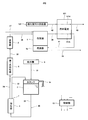
- FIG. 1 is a schematic diagram showing a schematic configuration of a fuel cell system according to Embodiment 1 of the present invention.
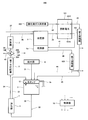
- FIG. 2 is a schematic diagram showing a schematic configuration of a fuel cell system according to Embodiment 2 of the present invention.
- FIG. 3 is a schematic diagram showing a schematic configuration of a fuel cell system according to Modification 1 of the present invention.
- FIG. 4 is a schematic diagram showing a schematic configuration of a fuel cell system according to Embodiment 3 of the present invention.
- FIG. 5 is a schematic diagram showing a schematic configuration of a fuel cell system according to Embodiment 4 of the present invention.
- FIG. 6 is a schematic diagram showing a schematic configuration of a fuel cell system according to Embodiment 5 of the present invention.
- FIG. 7 is a schematic diagram showing a schematic configuration of a fuel cell system according to Embodiment 6 of the present invention.
- FIG. 8 is a schematic diagram showing a schematic configuration of a fuel cell system according to Embodiment
- a fuel cell system includes a reformer that generates a fuel gas containing hydrogen from raw material gas and water vapor, a fuel cell that generates electric power using the fuel gas, a water tank that stores water, A water utilization device that uses water supplied from a water tank, a first water supply device that is provided in a water path from the water tank to the water utilization device, and that supplies water in the water tank to the water utilization device, and a water passage And a purifier for purifying water flowing through the water path, wherein the purifier has water in the purifier due to its own weight when the water tank is full in the water path. It is arranged to be stretched.
- the “full water level of the water tank” means the water level when the filling of the water tank is completed, and does not necessarily mean that the upper end of the water tank is filled with water.
- water is filled in the purifier
- the purifier is filled with water
- Embodiment 1 of this invention shows an example of the form whose water utilization apparatus is an evaporator.
- FIG. 1 is a schematic diagram showing a schematic configuration of a fuel cell system according to Embodiment 1 of the present invention.
- a fuel cell system 200 includes a reformer 1, a fuel cell 101, a water tank 3, an evaporator 2 that is a water utilization device, and a first water supplier 5. And the purifier 4, and the purifier 4 is disposed so that water is stretched in the purifier 4 by the weight of water when the water tank 3 is at the full water level.
- the full water level of the water tank 3 may be provided with a water level detector that detects the water level of the water tank 3, and the predetermined water level detected by the water level detector may be defined as the full water level. May be defined by providing in the water tank 3.
- the water tank 6 is connected to the water tank 3 through a water supply path 31.
- the water supply 6 is connected to, for example, a water pipe or a water tap (not shown), and the water supply 6 supplies water (here, tap water) to the water tank 3 through the water supply path 31.
- a water feeder 6 for example, a flow rate adjustment valve, an on-off valve, and a pump can be used.
- the upstream end of the water supply path 32 is connected to the lower part of the water tank 3 (here, the lower end surface of the water tank 3).
- the downstream end of the water supply path 32 is connected to the lower part (here, the lower end surface) of the purifier 4.
- the purifier 4 may be in any form as long as it can purify water.
- the purifier 4 is composed of a casing filled with an ion exchange resin.
- the purifier 4 is provided outside the water tank 3 and purifies the impurities (mainly ions) contained in the water by adsorbing them to the ion exchange resin.
- the form using an activated carbon filter or a reverse osmosis membrane is mentioned as forms other than the said ion exchange resin.
- the upstream end of the first water path 34 is connected to the upper part (here, the upper end surface) of the purifier 4, and the downstream end of the first water path 34 is connected to the first water supplier 5.
- the water supply path 32 is connected to the lower part of the purifier 4 and the first water path 34 is connected to the upper part of the purifier 4.
- the connection point between the path 32 and the first water path 34 may be any part of the purifier 4. However, from the viewpoint of sufficiently purifying the water supplied to the purifier 4, it is preferable that the connection points of the water supply path 32 and the first water path 34 are separated from each other.
- the first water supply device 5 may be in any form as long as it can adjust the flow rate of water supplied from the water tank 3 to the evaporator 2 which is a water-using device.
- the first water supply unit 5 may be constituted by a single flow rate adjustment valve or a single pump, or may be constituted by a combination of a pump and a flow rate adjustment valve.
- the evaporator 2 only needs to be configured to vaporize the water purified by the purifier 4 into water vapor.
- the vaporizer 2 vaporizes water by heat transfer of combustion exhaust gas generated by the combustor 1a described later. It may be configured as follows. Further, the evaporator 2 is connected to the reformer 1 through a steam supply path 36. As a result, the water purified by the purifier 4 is vaporized into steam by the evaporator 2, and the steam is supplied from the evaporator 2 to the reformer 1.
- a raw material gas supply path 37 is connected to the reformer 1, and the raw material gas supply path 37 is supplied from a raw material gas source (not shown) to the reformer 1 (for example, city gas mainly composed of methane). Supply.
- a raw material gas source for example, city gas mainly composed of methane.
- the source gas source include city gas (natural gas) infrastructure and LPG cylinders.
- a gas containing an organic compound having at least carbon and hydrogen as constituent elements can be used. Specific examples include gases containing hydrocarbons such as ethane and propane, gases containing gaseous alcohol, and the like.
- the reformer 1 is provided with a combustor 1a.
- the combustor 1 a is supplied with a combustion gas (combustible gas) such as a hydrogen-containing gas discharged from the reformer 1 or a fuel gas not used in the fuel cell 101 described later, and combustion air. It is configured to be.
- a combustion gas such as a hydrogen-containing gas discharged from the reformer 1 or a fuel gas not used in the fuel cell 101 described later
- combustion air It is configured to be.
- combustible exhaust gas is produced
- each apparatus such as the reformer 1 and the evaporator 2
- the combustion exhaust gas flows through the combustion exhaust gas path 39 and is discharged out of the fuel cell system 200 (in the atmosphere).
- a reforming catalyst (not shown) is provided in the internal space of the reformer 1, and the raw material gas supplied from the raw material gas supply path 37 and the steam supplied from the evaporator 2 are converted into a steam reforming reaction. Thus, a hydrogen-containing gas containing hydrogen is generated. Then, the hydrogen-containing gas generated in the reformer 1 is supplied as fuel gas to the fuel cell 101 through the fuel gas supply path 38.
- the hydrogen-containing gas generated in the reformer 1 is configured to be supplied to the fuel cell 101 as it is.
- the reformer 1 is provided downstream of the reformer 1. You may employ
- the fuel cell 101 has a fuel gas internal channel 101A and an oxidant gas internal channel 101B.
- a fuel gas supply path 38 is connected to the upstream end of the fuel gas internal flow path 101 ⁇ / b> A, and a combustor 1 a is connected to the downstream end thereof via an off fuel gas path 41.
- the upstream end of the oxidant gas internal flow passage 101B is connected to the oxidant gas supply device 102 via the oxidant gas supply passage 42, and the off-oxidant gas passage 43 is connected to the downstream end thereof.
- the oxidant gas supply unit 102 is configured to be able to supply an oxidant gas (for example, air) to the fuel cell 101.
- an oxidant gas for example, air
- fans such as a fan and a blower can be used. Note that the downstream end of the off-oxidant gas path 43 is open to the atmosphere.
- the fuel gas generated in the reformer 1 is supplied to the fuel gas internal flow path 101A of the fuel cell 101 via the fuel gas supply path 38. Further, the oxidant gas is supplied from the oxidant gas supply device 102 to the oxidant gas internal flow path 101 ⁇ / b> B of the fuel cell 101 through the oxidant gas supply path 42.
- the fuel gas supplied to the fuel gas internal channel 101A is supplied to the anode (not shown), and the oxidant gas supplied to the oxidant gas internal channel 101B is supplied to the cathode (not shown). Supplied.
- the fuel gas supplied to the anode and the oxidant gas supplied to the cathode react electrochemically to generate electricity and heat.
- the fuel gas that has not been used in the anode (hereinafter referred to as “off fuel gas”) is supplied to the combustor 1 a via the off fuel gas path 41 and used as a combustible gas for combustion.
- oxidant gas hereinafter referred to as off-oxidant gas
- off-oxidant gas oxidant gas that has not been used in the cathode flows through the off-oxidant gas path 43 and is discharged into the atmosphere.
- the type of fuel cell in the fuel cell system 200 is not limited.
- a polymer electrolyte fuel cell, a phosphoric acid fuel cell, a solid oxide fuel cell and the like are exemplified.
- the solid oxide fuel cell may be an external reforming type in which the reformer 1 and the fuel cell 101 are different, or an internal reforming type in which the reformer 1 and the fuel cell 101 are integrated. It doesn't matter.
- the fuel cell system 200 includes a controller 10.
- the controller 10 is constituted by, for example, a microcomputer and performs various controls relating to the fuel cell system 200.
- FIG. 1 shows the operation of the fuel cell system 200 according to the first embodiment, in particular, after the installation of the fuel cell system 200 or after long-term storage, or after the ion exchange resin of the purifier 4 is replaced.
- the description will be given with reference.
- the following operation is performed by the controller 10 controlling the fuel cell system 200.
- the water supply 6 supplies water to the water tank 3 through the water supply path 31.
- a part of the water supplied (stored) to the water tank 3 is supplied to the purifier 4 through the water supply path 32 (water filling of the purifier 4).
- the purifier 4 since the purifier 4 is located below the water surface in the water tank 3, the water in the water tank 3 is pumped to the purifier 4 by the position head. Then, by continuing the water supply to the water tank 3, it is possible to fill the purifier 4 with water without operating the first water supply device 5. That is, the fuel cell system 200 according to Embodiment 1 can perform the water filling of the purifier 4 by reducing the work amount of the first water supply device 5 as compared with the conventional fuel cell system.
- the fuel cell system 200 according to Embodiment 1 can suppress the consumption of electric power energy required for water filling of the purifier 4 as compared with the conventional fuel cell system.
- the controller 10 stores a water supply time that is obtained in advance through experiments or the like, in which the water level of the water tank 3 is full and the purifier 4 is filled with water. The water supply from the vessel 6 is stopped.
- the fuel cell system 200 according to the first embodiment is not limited to a mode in which the first water supply unit 5 is not operated at all in the water filling of the purifier 4. You may operate the 1st water supply device 5 in the range by which the power consumption of the 1st water supply device 5 required for water filling of the purifier 4 is suppressed compared with the conventional fuel cell system.
- the water feeder 6 stops supplying water.
- combustible gas and combustion air are supplied to the combustor 1a, and the combustor 1a burns the combustible gas and air to generate combustion exhaust gas.
- the combustion exhaust gas heats the reformer 1 and the evaporator 2, flows through the combustion exhaust gas path 39, and is discharged out of the fuel cell system 200.
- the combustion exhaust gas generation in the combustor 1 a may be performed simultaneously with the supply of water to the water tank 3 of the water supply device 6.
- the first water supply unit 5 is operated, and the water purified by the purifier 4 is supplied to the evaporator 2 via the first water path 34 and the second water path 35.
- the supplied water is vaporized into water vapor.
- the vaporized water vapor flows through the water vapor supply path 36 and is supplied to the reformer 1.
- the reformer 1 is supplied with a source gas via a source gas supply path 37.
- the raw material gas and steam undergo a steam reforming reaction to generate a hydrogen-containing gas containing hydrogen (hydrogen generation operation in the reformer 1).
- the hydrogen-containing gas generated in the reformer 1 flows as a fuel gas through the fuel gas supply path 38 and is supplied to the fuel gas internal flow path 101A of the fuel cell 101. Further, the oxidant gas is supplied from the oxidant gas supply device 102 to the oxidant gas internal flow path 101 ⁇ / b> B of the fuel cell 101 through the oxidant gas supply path 42.
- the fuel gas supplied to the anode and the oxidant gas supplied to the cathode react electrochemically to generate electricity and heat.
- the generated power is supplied to an external power load by a power regulator including at least one of an inverter and a converter.
- the off-fuel gas that has not been used at the anode is supplied to the combustor 1a via the off-fuel gas path 41 and used as a combustible gas for combustion.
- the off-oxidant gas that has not been used at the cathode flows through the off-oxidant gas path 43 and is discharged into the atmosphere.
- the fuel cell system 200 according to Embodiment 1 can suppress the power consumption of the first water supply device 5 compared to the prior art and perform water filling of the purifier 4, thereby improving energy saving performance. Can be made.
- the first water supply device 5 is provided on the downstream side of the purifier 4.
- the present invention is not limited to this, and the first water supply device 5 is disposed more than the purifier 4. You may employ
- Embodiment 2 of the present invention shows an example of a mode in which an exhaust port configured to exhaust gas in the purifier to the atmosphere is disposed in the purifier.
- the purifier is provided with an exhaust port configured to exhaust the gas in the purifier to the atmosphere.
- the exhaust port only needs to be able to exhaust the gas in the purifier to the atmosphere, and may be exhausted directly from the exhaust port to the atmosphere, or indirectly, for example, via a path communicating with the exhaust port. You may exhaust to air
- the fuel cell system according to Embodiment 2 includes a gas vent path that connects the exhaust port and the water tank, and the water tank is open to the atmosphere.
- FIG. 2 is a schematic diagram showing a schematic configuration of a fuel cell system according to Embodiment 2 of the present invention.
- the fuel cell system 200 according to Embodiment 2 of the present invention has the same basic configuration as the fuel cell system 200 according to Embodiment 1, but an overflow path 3a is provided in the water tank 3.
- the difference is that the exhaust port 7 is provided in the purifier 4 and the venting path 33 connecting the exhaust port 7 and the water tank 3 is provided.
- an overflow path 3a for defining the full position of the water tank 3 is provided in the water tank 3, and the downstream end of the overflow path 3a is open to the atmosphere.
- the purifier 4 is provided with an exhaust port 7, and the exhaust port 7 is connected to the water tank 3 through a gas vent path 33. More specifically, the downstream end of the gas vent path 33 is connected to a portion above the upstream end of the overflow path 3 a of the water tank 3. Thereby, when water is filled in the purifier 4, the gas (mainly air) in the purifier 4 is discharged from the exhaust port 7 to the atmosphere via the gas vent path 33 and the overflow path 3 a of the water tank 3. The That is, in the first embodiment, the water tank 3 is opened to the atmosphere by the overflow path 3a.
- the fuel cell system 200 according to the second embodiment configured as described above has the same effects as the fuel cell system 200 according to the first embodiment. Further, in the fuel cell system 200 according to Embodiment 2, since the purifier 4 is open to the atmosphere, when the purifier 4 is filled with water, an increase in the internal pressure of the water path including the purifier 4 is suppressed. The water supply to the purifier 4 can be made smoother.
- the atmosphere and the purifier 4 are configured to communicate with the atmosphere through the exhaust port 7, the gas vent path 33, the space on the water surface of the water tank 3, and the overflow pipe 3a.
- the present invention is not limited to this.
- a mode of simply communicating with the atmosphere via the exhaust port 7 may be employed. In this case, whether or not the overflow pipe 3a is provided is arbitrary.
- the modification of the second embodiment shows an example in which an exhaust port is provided in the first water path.
- FIG. 3 is a schematic diagram showing a schematic configuration of a fuel cell system according to Modification 1 of the present invention.
- the exhaust port 7 is provided in the middle of the first water path 34, and the upstream end of the gas vent path 33 is the first water path 34.
- the exhaust port 7 is connected.
- the gas vent path 33 is not provided and the air is simply communicated with the atmosphere via the exhaust port 7 may be employed.
- whether or not the overflow pipe 3a is provided is arbitrary.
- Embodiment 3 of the present invention shows an example in which the first valve is provided in the gas vent path.
- the fuel cell system according to Embodiment 3 is provided with a first valve that opens and closes the degassing path in the degassing path.
- the first valve opens and closes the gas venting path means that it is configured to permit / block the flow of gas and the like in the gas venting path by the opening and closing operation.
- an on-off valve such as an electromagnetic valve can be used as the “first valve”.
- the fuel cell system according to Embodiment 3 includes a controller.
- the controller opens the first valve when the purifier is filled with water, and operates to improve the reformer to generate a hydrogen-containing gas.
- the first valve is controlled to be closed when the hydrogen generation operation in the mass device is performed.
- the controller only needs to be able to control the first water supply device and the first valve.
- the controller can be constituted by, for example, a microcomputer, a logic circuit, or the like. Further, the controller means not only a single controller but also a controller group in which a plurality of controllers cooperate to execute control of the fuel cell system. For this reason, the controller does not need to be composed of a single controller, and a plurality of controllers may be arranged in a distributed manner so that they cooperate to control the fuel cell system.
- “to fill the purifier with water” means to supply water to the purifier and fill the purifier with water.
- the purifier when the purifier is filled with water, the gas in the purifier is discharged to the water tank via the gas venting path, so that water can be smoothly supplied to the purifier.
- the fuel cell system performs a power generation operation (reformer hydrogen generation operation)
- the first valve closes the degassing path, so that water and gas in the water tank flows back through the degassing path for purification. Mixing in the vessel is suppressed. For this reason, supply of water that has not been sufficiently purified to the evaporator is reduced. Further, the possibility that gas is mixed into the first water path and the first water path and the like are blocked is reduced. Furthermore, the possibility that gas is mixed into the first water supply unit and the supply amount thereof fluctuates (so-called air biting) is reduced.
- the fuel cell system according to Embodiment 3 includes a first water level detector that detects the water level of the purifier.
- the first water level detector may be in any form as long as it can detect the water level of the purifier and output the detected water level to the controller.
- the water level may be detected, or the water level of the purifier may be detected indirectly.
- a float switch can be used as the first water level detector.
- FIG. 4 is a schematic diagram showing a schematic configuration of the fuel cell system according to the third embodiment.
- the fuel cell system 200 according to the third embodiment of the present invention has the same basic configuration as the fuel cell system 200 according to the second embodiment, 1 valve 11 is provided, and the 1st water level detector 12 which detects the water level of the purifier 4 differs.
- the degassing path 33 has a degassing path upstream part 33A and a degassing path downstream part 33B, and the water level is connected to the degassing path upstream part 33A and the degassing path downstream part 33B.
- a detection tank 13 is provided.
- the water level detection tank 13 is provided so as to cover a predetermined range including the height of the upstream end of the overflow path 3 a of the water tank 3.
- the water level detection tank 13 is provided with a first water level detector 12 that detects the water level of the water level detection tank 13.
- the first water level detector 12 detects the water level of the water level detection tank 13. To do. Conversely, when the first water level detector 12 detects the water level in the water level detection tank 13, the purifier 4 is filled with water, and the first water level detector 12 indicates that the water level of the purifier 4 is It can be detected that the water level is full.
- the first valve 11 is provided in the middle of the degassing path upstream portion 33A, but is not limited thereto, and may be provided in the middle of the degassing path downstream portion 33B. Good.
- the controller 10 controls the first valve 11 to open the gas vent path 33 (more precisely, the gas vent path upstream portion 33A).
- water is supplied from the water supply 6 to the water tank 3.
- the purifier 4 is filled with water, flows through the degassing path upstream portion 33A, and water is supplied to the water level detection tank 13, the first water level detector 12 detects the water level of the water level detection tank 13. Then, a detection signal is output to the controller 10.
- the controller 10 determines that the water in the purifier 4 is filled, stops the water supply 6, and controls the first valve 11. Thus, the gas vent path 33 (more precisely, the gas vent path upstream portion 33A) is closed. Next, the controller 10 operates the first water supply device 5 so that the water purified by the purifier 4 is supplied to the evaporator 2 via the first water path 34 and the second water path 35. At this time, since the first valve 11 closes the gas vent path 33, water and gas (mainly air) in the water level detection tank 13 flows back through the gas vent path upstream portion 33 ⁇ / b> A and enters the purifier 4. Is suppressed.
- the controller 10 operates the water supply 6. And if the 1st water level detector 12 detects that the water level in the water level detection tank 13 increased to the predetermined
- the first water level detector 12 detects the water level (full water level) of the purifier 4 to easily detect that the water filling of the purifier 4 has ended. can do.
- the water level detection tank 13 is provided and the first water level detector 12 is disposed in the water level detection tank 13.
- the present invention is not limited to this, and the water level detection tank 13 is directly in the purifier 4.
- the first water level detector 12 may be arranged, or the first water level detector 12 may be arranged in the gas vent path 33.
- Embodiment 4 of the present invention shows an example in which the first water level detector indirectly detects the water level of the purifier.
- the first water level detector correlated with the water level of the purifier is configured to detect the water level of the water tank.
- the fuel cell system according to Embodiment 4 includes a water supply device that supplies water to the water tank, and a controller.
- the controller Stop water supply.
- the controller restarts the water supply when the first water level detector detects a drop in the water level after stopping the water supply of the water supply.
- FIG. 5 is a schematic diagram showing a schematic configuration of a fuel cell system according to Embodiment 4 of the present invention.
- the fuel cell system 200 according to Embodiment 4 of the present invention has the same basic configuration as the fuel cell system 200 according to Embodiment 2, but the first water level detector 12 is water The difference is that it is provided in the tank 3. Specifically, the first water level detector 12 is configured to detect the water level in the water tank 3 when the purifier 4 is filled with water.
- the water supply device 6 supplies water to the water tank 3 through the water supply path 31.
- a part of the water supplied (stored) to the water tank 3 is supplied to the purifier 4 via the water supply path 32.
- the first water level detector 12 detects the water level in the water tank 3 and outputs a detection signal to the controller 10.
- the controller 10 determines that the purifier 4 is filled with water, and stops the supply of water from the water supply 6 to the water tank 3. .
- the controller 10 causes the combustor 1a to supply combustible gas and combustion air, and causes the combustor 1a to generate combustion exhaust gas.
- the controller 10 operates the first water supply unit 5.
- the first water supply unit 5 When the first water supply unit 5 is activated, water is supplied from the water tank 3 to the purifier 4. Further, after the operation of the first water supply device 5, the first water level detector 12 outputs a detection signal to the controller 10 when detecting that the water level of the water tank 3 has fallen by a predetermined amount, for example.
- the controller 10 When the detection signal from the first water level detector 12 is input, the controller 10 operates the water supply 6. Then, when water is supplied to the water tank 3 and the first water level detector 12 detects that the water level of the water tank 3 has increased by a predetermined amount, for example, a detection signal is output to the controller 10. As described above, the controller 10 controls the operation of the water feeder 6 according to the water level of the water tank 3 detected by the first water level detector 12, so that water can be stably stored in the water tank 3. . For this reason, the supply stop of the steam to the reformer 1 due to the absence of water in the water tank 3 is suppressed, and the hydrogen generation operation can be performed stably.
- the water supplied to the purifier 4 is purified, vaporized into water vapor by the evaporator 2, and supplied to the reformer 1.
- a hydrogen generation operation is performed in which the raw material supplied via the raw material gas supply path 37 reacts with water vapor to generate a hydrogen-containing gas.
- the fuel cell system 200 according to the fourth embodiment configured as described above has the same effects as the fuel cell system 200 according to the first embodiment. Further, in the fuel cell system 200 according to Embodiment 4, when the first water level detector 12 detects the water level (full water level) of the purifier 4, it is easily detected that the water filling of the purifier 4 has been completed. can do.
- the first valve 11 is not provided in the gas vent path 33.
- the present invention is not limited to this, and the first valve 11 may be provided as in the third embodiment. Good.
- the controller 10 opens the first valve 11 when the purifier 4 is filled with water, and performs an operation (hydrogen generation operation) in which the reformer 1 generates a hydrogen-containing gas.
- the first valve 11 is controlled to be closed.
- the gas mainly air
- route 34 etc. will be obstruct
- the possibility that gas is mixed into the first water supply device 5 and the supply amount thereof fluctuates (so-called air biting) is reduced.
- Embodiment 5 of the present invention shows an example in which a third water path having an open end opened to the atmosphere is provided in the middle of the second water path connecting the first water supply unit and the evaporator. Is.
- the fuel cell system according to Embodiment 5 uses the water path from the purifier to the evaporator as the second water path, the third water path having an open end branched from the second water path and opened to the atmosphere, A first switching device that selectively connects the first water supply device to the evaporator and the open end of the third water path; and a controller, wherein the first water level detector is the water level of the purifier. When it is detected that the water is full, the first water supply device is operated with the first switch connected to the first water supply device and the open end of the third water path.
- the gas (mainly air) in the first water supplier can be discharged to the atmosphere, and the possibility that the supply amount of the first water supplier will fluctuate is reduced. Moreover, possibility that gas will mix into a 2nd water path
- FIG. 6 is a schematic diagram showing a schematic configuration of a fuel cell system according to Embodiment 5 of the present invention.
- the fuel cell system 200 according to Embodiment 5 of the present invention has the same basic configuration as the fuel cell system 200 according to Embodiment 4, but is branched from the second water path 35.
- the third water path 40 and the first switch 14 that selectively connects the first water supply device 5 to the evaporator 2 and the open end of the third water path 40 are different.
- the second water path 35 has a second water path upstream part 35A and a second water path downstream part 35B, and connects the second water path upstream part 35A and the second water path downstream part 35B.
- a first switch 14 configured by a three-way valve is provided. More specifically, the second water path upstream portion 35A connects the first water feeder 5 and the first port 14A of the first switch 14, and the second water path downstream portion 35B is connected to the first switch 14. The third port 14C and the evaporator 2 are connected. Further, the upstream end of the third water path 40 is connected to the second port 14B of the first switch 14. The downstream end of the third water path 40 is open to the atmosphere.
- the fuel cell system 200 includes a first condenser 103 and a second condenser 104.
- the first condenser 103 is provided in the middle of the combustion exhaust gas path 39
- the second condenser 104 is provided in the middle of the off-oxidant gas path 43.
- the first condenser 103 can use, for example, a heat exchanger, and is configured such that water vapor contained in the combustion exhaust gas is condensed into water.
- the second condenser 104 can use, for example, a heat exchanger, and is configured such that water vapor contained in the off-oxidant gas is condensed into water.
- the flue gas generated in the combustor 1 a is supplied to the first condenser 103 via the flue gas path 39, and the water condensed in the first condenser 103 passes through the first condensed water path 44.
- the water is supplied to the water tank 3.
- the off-oxidant gas is supplied to the second condenser 104 via the off-oxidant gas path 43, and the water condensed in the second condenser 104 flows through the second condensed water path 45 to form water. It is supplied to the tank 3.
- the controller 10 supplies water from the water supply 6 to the water tank 3. Then, when the first water level detector 12 detects that the purifier 4 has reached the full water level, the controller 10 stops the water supply device 6.
- the controller 10 connects the first port 14A and the second port 14B of the first switch 14 and shuts off the third port 14C, so that the first water supply unit 5 and the third water path are connected.
- the 40 open ends (downstream ends) are connected.
- the controller 10 operates the first water supply device 5 to remove the water purified by the purifier 4 from the first water path 34, the first water supply device 5, the second water path upstream portion 35A, and the first water path 35A.
- Three water paths 40 are made to flow.
- the gas mainly air
- the gas present in the first water path 34, the first water supplier 5, and the second water path upstream portion 35 ⁇ / b> A is discharged from the open end of the third water path 40 to the atmosphere.
- the amount of water supplied from the first water supply device 5 to the evaporator 2 may fluctuate, or the first water path 34 and the second water path 35. Is less likely to be occluded.
- the controller 10 causes the first port 14A and the third port 14C of the first switch 14 to communicate with each other after a predetermined time has elapsed, shuts off the second port 14B, and supplies water to the evaporator 2.
- the predetermined time is a time obtained in advance through experiments or the like, and the water purified by the purifier 4 is upstream of the first water path 34, the first water supply unit 5, and the second water path. The time required to discharge the gas present in the portion 35A from the open end of the third water path 40 to the extent that the first water path 34 and the second water path 35 are not likely to be blocked.
- the water supplied to the purifier 4 is purified, vaporized into water vapor by the evaporator 2, and supplied to the reformer 1.
- the fuel cell system 200 according to the fifth embodiment configured as described above has the same effects as the fuel cell system 200 according to the fourth embodiment. Further, in the fuel cell system 200 according to Embodiment 5, there is a possibility that the amount of water supplied from the first water supplier 5 to the evaporator 2 varies after the supply of water to the evaporator 2 is started. The possibility that the first water path 34 and the second water path 35 are blocked is reduced.
- the first water level detector 12 is provided in the water tank 3.
- the water level detection tank 13 may be provided in the middle of 33 and the first water level detector 12 may be provided in the water level detection tank 13, and the first water level detector 12 may be provided in the purifier 4 or the gas vent path 33. It is good also as a structure which provides.
- the first condenser 103 and the second condenser 104 are provided.
- the present invention is not limited to this, and one of the first condenser 103 and the second condenser 104 is used. You may employ
- Embodiment 6 of the present invention shows an example in which the water utilization device is a cooling water tank that stores cooling water for cooling the fuel cell.
- the fuel cell system according to Embodiment 6 of the present invention includes an exhaust port in which a cooling water tank that is a water-using device is opened to the atmosphere.
- the purifier when the purifier is water-filled, the gas in the purifier is discharged through the cooling water tank, so that water can be smoothly supplied to the purifier.
- the purifier when the water tank is full in the water path from the water tank to the cooling water tank, the purifier has water in the purifier due to its own weight. It is arranged to be stretched.
- the first water supplier is provided on the upstream side of the purifier, and the first water supplier is in the water path from the water tank to the cooling water tank.
- the first water supply unit is arranged so that water is stretched by its own weight.
- FIG. 7 is a schematic diagram showing a schematic configuration of a fuel cell system according to Embodiment 6 of the present invention.
- the fuel cell system 200 according to the sixth embodiment of the present invention has the same basic configuration as the fuel cell system 200 according to the first embodiment.
- the difference is that 105 is provided.
- the cooling water tank 105 is connected to the water tank 3 through the water path 30 and is configured to store water purified by the purifier 4 as cooling water.
- the purifier 4 is disposed on the downstream side of the first water supply unit 5.
- an overflow path 105 a is connected to the cooling water tank 105.
- the downstream end of the overflow path 105a is open to the atmosphere.
- the gas (mainly air) in the purifier 4 is discharged into the atmosphere via the water path 30 and the overflow path 105 a of the cooling water tank 105. That is, in the sixth embodiment, the cooling water tank 105 is opened to the atmosphere by the overflow path 105a.
- the overflow path 105a is an example of an exhaust port provided in the cooling water tank 105, and is not limited to this.
- a configuration in which the cooling water tank 105 is not provided with the overflow path 105a as an exhaust port but the cooling water tank 105 is directly provided with an exhaust port may be employed.
- the cooling water tank 105 is provided on the cooling water path 50 through which the cooling water flows.
- the cooling water path 50 that flows inside the fuel cell 101 is the cooling water internal path 101C.
- the cooling water in the cooling water tank 105 is supplied to the fuel cell 101 via the cooling water path 50, and the heat generated in the fuel cell 101 during the flow through the cooling water internal flow path 101C is recovered to produce the fuel.
- the battery 101 is discharged.
- water may be supplied to the evaporator 2 from a branch path provided in the water path 30. Further, as will be described later, the cooling water may be supplied from the cooling water tank 105 to the evaporator 2.
- the water supply device 6 supplies water to the water tank 3 through the water supply path 31.
- a part of the water supplied (stored) to the water tank 3 is supplied to the purifier 4 via the water path 30.
- the purifier 4 since the purifier 4 is located below the water surface in the water tank 3, the water in the water tank 3 is pumped to the purifier 4 by the position head.
- the first water supply unit 5 is provided in the water path 30 upstream of the purifier 4 and the first water supply unit 5 is located below the water surface in the water tank 3, so that the The water in the tank 3 is also pumped to the first water supplier 5. Then, by continuing the water supply to the water tank 3, the purifier 4 and the first water supply device 5 can be filled with water without operating the first water supply device 5.
- the purifier 4 is opened to the atmosphere via the overflow path 105a of the cooling water tank 105.
- the supply of water to the purifier 4 can be made smoother. This is because when the cooling water tank 105 is not provided with an exhaust port, the internal pressure of the water passage 30 increases with the supply of water to the purifier 4, and water filling of the purifier 4 is hindered.
- the fuel cell system 200 according to the sixth embodiment configured as described above has the same effects as the fuel cell system 200 according to the first embodiment. Further, in the fuel cell system 200 according to Embodiment 6, the power consumption of the first water supplier 5 is reduced as compared with the conventional case, and not only the purifier 4 but also the first water supplier 5 is filled with water. Is possible. Further, in the fuel cell system 200 according to Embodiment 6, since the inside of the first water supplier 5 can be filled with water, it is possible to reduce the occurrence of air biting and idling of the first water supplier 5. it can.
- the fuel cell system 200 according to Embodiment 6 is not limited to a mode in which the first water supply unit 5 is not operated at all in the water filling of the purifier 4. Even if the first water supply 5 is operated in a range where the power consumption of the first water supply 5 required for water filling of the purifier 4 and the first water supply 5 is suppressed as compared with the conventional fuel cell system. I do not care.
- the cooling water tank 105 is provided with an exhaust port.
- the exhaust port may be provided at any location as long as it is a purifier and a downstream water path. Examples of the downstream water path include water paths such as the water path 30, the cooling water tank 105, and the cooling water path 50.
- a mode in which an exhaust port is provided in the purifier 4 may be adopted.
- an embodiment in which an exhaust port is provided in the water path 30 downstream of the purifier 4 may be employed.
- Embodiment 7 of the present invention shows an example of a form in which the water utilization device is a cooling water tank and water is supplied from the cooling water tank to the evaporator.
- the water utilization device is a cooling water tank, and the second water level detector that detects the water level in the cooling water tank, the cooling water path, and the evaporator are connected.
- a fourth water path, a second water feeder provided in the fourth water path, a branch path having an open end branched from the fourth water path and opened to the atmosphere, and the second water feeder as an evaporator A second switch that is selectively connected to the branch path; and a controller.
- the controller detects that the water level of the cooling water tank is a predetermined water level, the controller detects the second level.
- the second water supply unit is operated in a state where the second water supply unit and the open end of the branch path are connected by the switch.
- the second water supply unit may be in any form as long as the flow rate of water can be adjusted and supplied to the evaporator.
- the second water supply unit may be configured by a single flow rate adjustment valve or a single pump.
- it may be configured by a combination of a pump and a flow rate adjusting valve.
- the second water level detector may be in any form as long as it can detect the water level of the cooling water tank and output the detected water level to the controller.
- the second water level detector directly controls the water level of the cooling water tank.
- the water level of the cooling water tank may be detected indirectly.
- a float switch can be used as the second water level detector.
- the second switching device may be in any form as long as the second water supply device can be selectively connected to the evaporator and the open end of the branch path, and is composed of, for example, a three-way valve.
- the second water feeder can be selectively used as an evaporator and an open end of the branch path. You may connect to.
- the gas in the second water supplier can be discharged to the atmosphere, and the water (cooling water) can be smoothly supplied to the evaporator.
- the fuel cell system according to Embodiment 7 of the present invention includes a cooling water supplier, and the controller is configured to operate the second water supplier and the cooling water supplier. .
- the 2nd water supply device can reduce idling.
- the cooling water supply device may be in any form as long as the flow rate of the cooling water can be adjusted and supplied to the fuel cell.
- the cooling water supply device may be constituted by a single flow rate adjustment valve or a single pump. Moreover, it may be configured by a combination of a pump and a flow rate adjusting valve.
- FIG. 8 is a schematic diagram showing a schematic configuration of a fuel cell system according to Embodiment 7 of the present invention.
- the fuel cell system 200 according to Embodiment 7 of the present invention has the same basic configuration as the fuel cell system 200 according to Embodiment 6, but the second water level detector 106, The difference is that a two-water supply unit 107, a second switching unit 108, a fourth water path 48, and a branch path 49 are provided.
- the fourth water path 48 has an upstream end connected to the cooling water path 50 and a downstream end connected to the evaporator 2.
- a second water supply device 107 is provided in the middle of the fourth water path 48.
- the second water supply unit 107 may take any form as long as it is configured to supply the water in the cooling water path 50 and the water in the cooling water tank 105 to the evaporator 2. It may be.
- a second switch 108 is provided in a portion of the fourth water path 48 on the downstream side of the second water supplier 107.
- a branch path 49 is connected to the second switch 108.
- the fuel cell system 200 includes a cooling water supply device 109, and the cooling water supply device 109 is provided in the cooling water path 50.
- the cooling water supplier 109 may have any form as long as it is configured to supply the water in the cooling water tank 105 to the cooling water internal flow path 101C via the cooling water supply path 50.
- a pump having a large discharge amount may be used.
- the controller 10 supplies water from the water supply device 6 to the water tank 3 to fill the first water supply device 5 and the purifier 4 with water.
- the water tank 3 reaches a predetermined water level (for example, full water level)
- the first water supply unit 5 is operated to supply the water in the water tank 3 to the cooling water tank 105.
- the water flowing through the water path 30 is purified by the purifier 4 and supplied to the cooling water tank 105.
- the water feeder 6 may be stopped when the water tank 3 reaches a predetermined water level, or may operate so as to maintain the predetermined water level.
- the controller 10 detects the second water supply 107 and the open end (downstream end) of the branch path 49. Connect to. Next, the controller 10 operates the second water supply unit 107 to pass the water (cooling water) in the cooling water tank 105 to the fourth water path 48 via the cooling water path 50. As a result, the gas in the water path A from the cooling water tank 105 to the second switching device 108 is discharged to the atmosphere, and after the supply of water to the evaporator 2 is started, the second water supply device 107 is engaged with air. The fluctuation of the flow rate can be suppressed.
- the controller 10 also operates the cooling water supply 109 in order to reduce the inflow of gas from the cooling water path 50 to the fourth water path 48 during the degassing operation of the water path A. Thereby, the inflow amount of the gas to the 4th water path 48 is reduced, and the idling of the 2nd water supply device 107 can be reduced.
- the controller 10 operates the second switch 108 to connect the second water supplier 107 to the evaporator 2 and supply water to the evaporator 2.
- the predetermined time refers to a time required for releasing the gas in the water path A to the atmosphere via the branch path 49.
- the water supplied to the evaporator 2 is vaporized into water vapor by the evaporator 2 and supplied to the reformer 1.
- the first water supply device 5 is disposed downstream of the purifier 4.
- the present invention is not limited to this, and a form in which the first water supply device 5 is disposed upstream of the purifier 4 may be employed.
- the first water supply device 5 is disposed upstream of the purifier 4, but is not limited thereto.
- the first water supply device 5 may be disposed downstream of the purifier 4.
- the cooling water tank 105 is provided with an exhaust port as one mode of providing the exhaust port in at least one of the purifier and the downstream water path. It was adopted. However, the present invention is not limited to this, and a mode in which no exhaust port is provided in any of the purifier and the downstream water path may be adopted.
- the fuel cell system of the present invention is arranged so that water is stretched on the purifier by its own weight when the water tank is at the full water level, the consumption of the water supply required for water filling the purifier Since electric power can be reduced as compared with the prior art, it is useful in the field of fuel cells.
Landscapes
- Chemical & Material Sciences (AREA)
- Chemical Kinetics & Catalysis (AREA)
- Engineering & Computer Science (AREA)
- Sustainable Development (AREA)
- General Chemical & Material Sciences (AREA)
- Electrochemistry (AREA)
- Sustainable Energy (AREA)
- Life Sciences & Earth Sciences (AREA)
- Manufacturing & Machinery (AREA)
- Organic Chemistry (AREA)
- General Health & Medical Sciences (AREA)
- Inorganic Chemistry (AREA)
- Combustion & Propulsion (AREA)
- Health & Medical Sciences (AREA)
- Fuel Cell (AREA)
Abstract
Description
本発明の実施の形態1は、水利用機器が蒸発器である形態の一例を示すものである。
図1は、本発明の実施の形態1に係る燃料電池システムの概略構成を示す模式図である。
次に、本実施の形態1に係る燃料電池システム200の動作、特に、燃料電池システム200の設置後や長期保管後、または、浄化器4のイオン交換樹脂を交換後の動作について、図1を参照しながら説明する。なお、以下の動作は、制御器10が燃料電池システム200を制御することにより遂行される。
本発明の実施の形態2は、浄化器に該浄化器内のガスを大気に排気するように構成された排気口が配設されている形態の一例を示すものである。
次に、実施の形態2に係る燃料電池システム200の変形例について説明する。
本発明の実施の形態3は、ガス抜き経路に第1弁が設けられた形態の一例を示すものである。
次に、本発明の実施の形態3に係る燃料電池システムの構成について、図4を参照しながら説明する。
次に、本実施の形態4に係る燃料電池システムの動作について、図4を参照しながら説明する。なお、改質器1の水素生成運転以降の動作については、実施の形態1と同様に行われるので、その詳細な説明は省略する。
本発明の実施の形態4は、第1水位検知器が、間接的に浄化器の水位を検知する形態の一例を示すものである。
図5は、本発明の実施の形態4に係る燃料電池システムの概略構成を示す模式図である。
次に、本実施の形態4に係る燃料電池システムの動作について、図5を参照しながら説明する。なお、改質器1の水素生成運転以降の動作については、実施の形態1と同様に行われるので、その詳細な説明は省略する。
本発明の実施の形態5は、第1水供給器と蒸発器とを接続する第2水経路の途中に、大気開放された開放端を有する第3水経路が設けられた形態の一例を示すものである。
図6は、本発明の実施の形態5に係る燃料電池システムの概略構成を示す模式図である。
次に、本実施の形態5に係る燃料電池システム200の動作について、図6を参照しながら説明する。なお、改質器1の水素生成運転以降の動作については、実施の形態1と同様に行われるので、その詳細な説明は省略する。
本発明の実施の形態6は、水利用機器が燃料電池を冷却する冷却水を貯える冷却水タンクである形態の一例を示すものである。
図7は、本発明の実施の形態6に係る燃料電池システムの概略構成を示す模式図である。
次に、本実施の形態6に係る燃料電池システム200の動作について、図7を参照しながら説明する。なお、改質器1の水素生成運転以降の動作については、実施の形態1と同様に行われるので、その詳細な説明は省略する。
本発明の実施の形態7は、水利用機器が冷却水タンクであり、冷却水タンクから蒸発器に水を供給する形態の一例を示すものである。
図8は、本発明の実施の形態7に係る燃料電池システムの概略構成を示す模式図である。
次に、本実施の形態7に係る燃料電池システム200の動作について、図8を参照しながら説明する。なお、水素生成装置100の水素生成運転以降の動作については、実施の形態1と同様に行われるので、その詳細な説明は省略する。
1a 燃焼器
2 蒸発器
3 水タンク
3a オーバーフロー路
4 浄化器
5 第1水供給器
6 給水器
7 排気口
10 制御器
11 第1弁
12 第1水位検知器
13 水位検知タンク
14 第1切り替え器
14A 第1ポート
14B 第2ポート
14C 第3ポート
30 水経路
31 給水経路
32 水供給路
33 ガス抜き経路
33A ガス抜き経路上流部
33B ガス抜き経路下流部
34 第1水経路
35 第2水経路
35A 第2水経路上流部
35B 第2水経路下流部
36 水蒸気供給路
37 原料ガス供給路
38 燃料ガス供給路
39 燃焼排ガス経路
40 第3水経路
41 オフ燃料ガス経路
42 酸化剤ガス供給路
43 オフ酸化剤ガス経路
44 第1凝縮水経路
45 第2凝縮水経路
48 第4水経路
49 分岐経路
50 冷却水経路
101 燃料電池
101A 燃料ガス内部流路
101B 酸化剤ガス内部流路
101C 冷却水内部流路
102 酸化剤ガス供給器
103 第1凝縮器
104 第2凝縮器
105 冷却水タンク
105a オーバーフロー路
106 第2水位検知器
107 第2水供給器
108 第2切り替え器
109 冷却水供給器
200 燃料電池システム
Claims (14)
- 原料ガスと水蒸気から水素を含む燃料ガスを生成する改質器と、
前記燃料ガスを用いて発電する燃料電池と、
水を貯水する水タンクと、
前記水タンクから供給された前記水を利用する水利用機器と、
前記水タンクから前記水利用機器までの水経路に設けられ、前記水タンク内の前記水を前記水利用機器に供給する第1水供給器と、
前記水経路を通流する前記水を浄化する浄化器と、を備え、
前記浄化器は、前記水経路において、前記水タンクが満水位であるときに前記水の自重により該浄化器内に水が張られるように配設されている、燃料電池システム。 - 前記浄化器から前記第1水供給器までの前記水経路を第1水経路とし、
前記浄化器及び前記第1水経路の少なくともいずれか一方には、前記浄化器内のガスを大気に排気するように構成された排気口が配設されている、請求項1に記載の燃料電池システム。 - 前記排気口と前記水タンクとを接続するガス抜き経路を備え、
前記水タンクは大気開放されている、請求項2に記載の燃料電池システム。 - 前記ガス抜き経路には、該ガス抜き経路を開閉する第1弁が設けられている、請求項3に記載の燃料電池システム。
- 制御器を備え、
前記制御器は、前記浄化器の水張りをするときには前記第1弁を開放し、
前記改質器の水素生成運転をするときには前記第1弁を閉鎖するように制御する、請求項4に記載の燃料電池システム。 - 前記水利用機器は大気開放されている、請求項1に記載の燃料電池システム。
- 前記浄化器は前記第1水供給器よりも下流側に設けられ、
前記第1水供給器は、前記水経路において、前記水タンクの満水位時に前記水の自重により該第1水供給器内に水が張られるように配設されている、請求項1に記載の燃料電池システム。 - 前記浄化器の水位を検知する第1水位検知器を備える、請求項1に記載の燃料電池システム。
- 前記第1水位検知器は前記水タンクの水位を検知して、前記浄化器の水位を検知するように構成されている、請求項8に記載の燃料電池システム。
- 前記水タンクに給水する給水器と、制御器と、を備え、
前記制御器は、前記第1水位検知器が前記水位の上昇を検知すると、前記給水器の給水を停止させる、請求項9に記載の燃料電池システム。 - 前記制御器は、前記給水器の給水を停止させた後に、前記第1水位検知器が前記水位の下降を検知すると、前記給水器の給水を再開させる、請求項10に記載の燃料電池システム。
- 前記水利用機器は、前記水蒸気を生成する蒸発器であり、
前記浄化器から前記蒸発器までの前記水経路を第2水経路とし、
前記燃料電池システムは、
前記第2水経路から分岐され、大気開放された開放端を有する第3水経路と、
前記第1水供給器を前記蒸発器と前記第3水経路の開放端とに選択的に接続する第1切り替え器と、
制御器と、を備え、
前記制御器は、前記第1水位検知器が前記浄化器の水位が満水であることを検知すると、前記第1切り替え器を前記第1水供給器と前記第3水経路の開放端とを接続させた状態で、前記第1水供給器を作動させる、請求項8に記載の燃料電池システム。 - 前記水利用機器は、前記燃料電池に冷却水経路を介して供給される水を貯える冷却水タンクであり、
前記燃料電池システムは、
前記水蒸気を生成する蒸発器と、
前記冷却水タンク内の水位を検知する第2水位検知器と、
前記冷却水経路と前記蒸発器とを接続する第4水経路と、
前記第4水経路に設けられ、前記蒸発器に前記水を供給する第2水供給器と、
前記第4水経路から分岐され、大気開放された開放端を有する分岐経路と、
前記第2水供給器を前記蒸発器と前記分岐経路の開放端とに選択的に接続する第2切り替え器と、
制御器と、を備え、
前記制御器は、前記第2水位検知器が前記冷却水タンクの水位が所定の水位であることを検知すると、前記第2切り替え器を前記第2水供給器と前記分岐経路の開放端とを接続させた状態で、前記第2水供給器を作動させる、請求項1に記載の燃料電池システム。 - 前記冷却水経路に設けられ、前記燃料電池に前記冷却水タンクの水を供給する冷却水供給器を備え、
前記制御器は、前記第2水供給器を作動させるとともに、前記冷却水供給器を作動させる、請求項13に記載の燃料電池システム。
Priority Applications (4)
| Application Number | Priority Date | Filing Date | Title |
|---|---|---|---|
| US13/382,385 US8962199B2 (en) | 2009-07-08 | 2010-07-08 | Fuel cell system |
| EP10796917.2A EP2452917B1 (en) | 2009-07-08 | 2010-07-08 | Fuel cell system |
| JP2011521824A JP5604429B2 (ja) | 2009-07-08 | 2010-07-08 | 燃料電池システム |
| CN2010800304971A CN102471055A (zh) | 2009-07-08 | 2010-07-08 | 燃料电池系统 |
Applications Claiming Priority (2)
| Application Number | Priority Date | Filing Date | Title |
|---|---|---|---|
| JP2009161968 | 2009-07-08 | ||
| JP2009-161968 | 2009-07-08 |
Publications (1)
| Publication Number | Publication Date |
|---|---|
| WO2011004606A1 true WO2011004606A1 (ja) | 2011-01-13 |
Family
ID=43429033
Family Applications (1)
| Application Number | Title | Priority Date | Filing Date |
|---|---|---|---|
| PCT/JP2010/004458 Ceased WO2011004606A1 (ja) | 2009-07-08 | 2010-07-08 | 燃料電池システム |
Country Status (5)
| Country | Link |
|---|---|
| US (1) | US8962199B2 (ja) |
| EP (1) | EP2452917B1 (ja) |
| JP (3) | JP5604429B2 (ja) |
| CN (1) | CN102471055A (ja) |
| WO (1) | WO2011004606A1 (ja) |
Cited By (3)
| Publication number | Priority date | Publication date | Assignee | Title |
|---|---|---|---|---|
| JP2012156039A (ja) * | 2011-01-27 | 2012-08-16 | Panasonic Corp | 燃料電池システム |
| JP2012155849A (ja) * | 2011-01-21 | 2012-08-16 | Aisin Seiki Co Ltd | 燃料電池システム |
| JP2017105700A (ja) * | 2015-12-07 | 2017-06-15 | パナソニックIpマネジメント株式会社 | 水素生成システムおよび燃料電池システム |
Families Citing this family (5)
| Publication number | Priority date | Publication date | Assignee | Title |
|---|---|---|---|---|
| US9437890B2 (en) * | 2013-06-25 | 2016-09-06 | Ford Global Technologies, Llc | Purge assembly for a fuel cell system |
| JP6235377B2 (ja) * | 2014-02-28 | 2017-11-22 | 日本特殊陶業株式会社 | 燃料電池システム及び燃料電池システムの制御装置並びに燃料電池システムの制御方法 |
| JP6534116B2 (ja) * | 2015-05-22 | 2019-06-26 | パナソニックIpマネジメント株式会社 | 固体酸化物形燃料電池システム |
| EP3660967B1 (en) * | 2017-07-27 | 2022-05-25 | Dainichi Co., Ltd. | Fuel cell device |
| CN111377403B (zh) * | 2020-04-23 | 2024-07-19 | 大方元素(广东)科技有限公司 | 一种静默紧凑型可移动甲醇低温液相重整制氢系统 |
Citations (8)
| Publication number | Priority date | Publication date | Assignee | Title |
|---|---|---|---|---|
| JPH07320766A (ja) * | 1994-05-26 | 1995-12-08 | Toshiba Corp | 燃料電池水回収システム |
| JPH10223246A (ja) * | 1997-02-06 | 1998-08-21 | Toshiba Corp | リン酸型燃料電池発電プラント |
| JP2001338668A (ja) | 2000-05-26 | 2001-12-07 | Matsushita Electric Ind Co Ltd | 燃料電池発電装置 |
| JP2005100693A (ja) * | 2003-09-22 | 2005-04-14 | Toyota Industries Corp | 燃料電池の冷却システム |
| JP2005166404A (ja) * | 2003-12-02 | 2005-06-23 | Nissan Motor Co Ltd | 燃料電池システム |
| JP2005235586A (ja) * | 2004-02-19 | 2005-09-02 | Aisin Seiki Co Ltd | 燃料電池システム |
| JP2008135271A (ja) | 2006-11-28 | 2008-06-12 | Kyocera Corp | 燃料電池装置 |
| WO2009047897A1 (ja) * | 2007-10-11 | 2009-04-16 | Panasonic Corporation | 燃料電池システム |
Family Cites Families (23)
| Publication number | Priority date | Publication date | Assignee | Title |
|---|---|---|---|---|
| JP2800286B2 (ja) | 1989-07-26 | 1998-09-21 | 富士電機株式会社 | 燃料電池の生成水回収装置 |
| DE4425634C1 (de) * | 1994-07-20 | 1995-10-26 | Daimler Benz Ag | Verfahren und Vorrichtung zum dosierten Zuführen von flüssigen Reaktanden zu einem Brennstoffzellensystem |
| JP2776279B2 (ja) * | 1994-11-30 | 1998-07-16 | 三浦工業株式会社 | 軟水器の制御方法 |
| JP2002177932A (ja) | 2000-12-15 | 2002-06-25 | Fuji Electric Co Ltd | 廃棄物処理用凝縮器 |
| JP2003031255A (ja) * | 2001-07-18 | 2003-01-31 | Matsushita Electric Ind Co Ltd | 燃料電池発電装置、及び凝縮水の貯水タンクへの供給方法 |
| JP2003249255A (ja) * | 2002-02-21 | 2003-09-05 | Matsushita Electric Ind Co Ltd | 燃料電池システム |
| JP2004234965A (ja) | 2003-01-29 | 2004-08-19 | Nissan Motor Co Ltd | 燃料電池システム |
| JP4585449B2 (ja) | 2003-07-01 | 2010-11-24 | ヤマハ発動機株式会社 | ダイレクトメタノール型燃料電池システム |
| JP5001511B2 (ja) | 2003-09-29 | 2012-08-15 | トヨタ自動車株式会社 | 燃料電池システム |
| JP2006107893A (ja) | 2004-10-05 | 2006-04-20 | Matsushita Electric Ind Co Ltd | 燃料電池発電システム |
| JP2006164837A (ja) | 2004-12-09 | 2006-06-22 | Toshiba Fuel Cell Power Systems Corp | 固体高分子型燃料電池システム |
| US20090130529A1 (en) | 2005-02-18 | 2009-05-21 | Matsushita Electric Industrial Co., Ltd. | Fuel Cell System and Operation Method Thereof |
| JP2007257953A (ja) | 2006-03-22 | 2007-10-04 | Matsushita Electric Ind Co Ltd | 燃料電池システム |
| JP2008027684A (ja) | 2006-07-20 | 2008-02-07 | Toyota Motor Corp | イオン交換器 |
| JP2008053158A (ja) | 2006-08-28 | 2008-03-06 | Toyota Motor Corp | 燃料電池システム |
| JP5162118B2 (ja) * | 2006-10-20 | 2013-03-13 | アイシン精機株式会社 | 燃料電池システム |
| JP2008175072A (ja) | 2007-01-16 | 2008-07-31 | Mitsubishi Heavy Ind Ltd | 湿分分離加熱器のドレン処理装置 |
| JP2008269807A (ja) * | 2007-04-16 | 2008-11-06 | Toshiba Fuel Cell Power Systems Corp | 燃料電池発電システム |
| JP5132205B2 (ja) * | 2007-06-27 | 2013-01-30 | 京セラ株式会社 | 燃料電池装置 |
| JP2009037830A (ja) | 2007-08-01 | 2009-02-19 | Aisin Seiki Co Ltd | 燃料電池システム |
| JP2009081084A (ja) * | 2007-09-27 | 2009-04-16 | Fuji Electric Holdings Co Ltd | 燃料電池発電装置 |
| JP2009129874A (ja) | 2007-11-28 | 2009-06-11 | Aisin Seiki Co Ltd | 燃料電池システム |
| JP5057295B2 (ja) * | 2008-10-24 | 2012-10-24 | 東芝ホームテクノ株式会社 | 燃料電池装置 |
-
2010
- 2010-07-08 EP EP10796917.2A patent/EP2452917B1/en not_active Not-in-force
- 2010-07-08 CN CN2010800304971A patent/CN102471055A/zh active Pending
- 2010-07-08 JP JP2011521824A patent/JP5604429B2/ja not_active Expired - Fee Related
- 2010-07-08 WO PCT/JP2010/004458 patent/WO2011004606A1/ja not_active Ceased
- 2010-07-08 US US13/382,385 patent/US8962199B2/en active Active
-
2013
- 2013-09-19 JP JP2013194228A patent/JP5877386B2/ja not_active Expired - Fee Related
- 2013-09-19 JP JP2013194227A patent/JP5793697B2/ja not_active Expired - Fee Related
Patent Citations (8)
| Publication number | Priority date | Publication date | Assignee | Title |
|---|---|---|---|---|
| JPH07320766A (ja) * | 1994-05-26 | 1995-12-08 | Toshiba Corp | 燃料電池水回収システム |
| JPH10223246A (ja) * | 1997-02-06 | 1998-08-21 | Toshiba Corp | リン酸型燃料電池発電プラント |
| JP2001338668A (ja) | 2000-05-26 | 2001-12-07 | Matsushita Electric Ind Co Ltd | 燃料電池発電装置 |
| JP2005100693A (ja) * | 2003-09-22 | 2005-04-14 | Toyota Industries Corp | 燃料電池の冷却システム |
| JP2005166404A (ja) * | 2003-12-02 | 2005-06-23 | Nissan Motor Co Ltd | 燃料電池システム |
| JP2005235586A (ja) * | 2004-02-19 | 2005-09-02 | Aisin Seiki Co Ltd | 燃料電池システム |
| JP2008135271A (ja) | 2006-11-28 | 2008-06-12 | Kyocera Corp | 燃料電池装置 |
| WO2009047897A1 (ja) * | 2007-10-11 | 2009-04-16 | Panasonic Corporation | 燃料電池システム |
Non-Patent Citations (1)
| Title |
|---|
| See also references of EP2452917A4 * |
Cited By (3)
| Publication number | Priority date | Publication date | Assignee | Title |
|---|---|---|---|---|
| JP2012155849A (ja) * | 2011-01-21 | 2012-08-16 | Aisin Seiki Co Ltd | 燃料電池システム |
| JP2012156039A (ja) * | 2011-01-27 | 2012-08-16 | Panasonic Corp | 燃料電池システム |
| JP2017105700A (ja) * | 2015-12-07 | 2017-06-15 | パナソニックIpマネジメント株式会社 | 水素生成システムおよび燃料電池システム |
Also Published As
| Publication number | Publication date |
|---|---|
| JP5793697B2 (ja) | 2015-10-14 |
| JP2014041829A (ja) | 2014-03-06 |
| JP2014038854A (ja) | 2014-02-27 |
| JPWO2011004606A1 (ja) | 2012-12-20 |
| EP2452917B1 (en) | 2017-05-03 |
| JP5877386B2 (ja) | 2016-03-08 |
| CN102471055A (zh) | 2012-05-23 |
| EP2452917A1 (en) | 2012-05-16 |
| EP2452917A4 (en) | 2012-12-19 |
| US8962199B2 (en) | 2015-02-24 |
| US20120107703A1 (en) | 2012-05-03 |
| JP5604429B2 (ja) | 2014-10-08 |
Similar Documents
| Publication | Publication Date | Title |
|---|---|---|
| JP5793697B2 (ja) | 燃料電池システム | |
| US9118053B2 (en) | Fuel cell system and method for performing maintenance on fuel cell system | |
| JP5528451B2 (ja) | 燃料電池装置 | |
| JP5422780B1 (ja) | 燃料電池システム | |
| JP2017068913A (ja) | 燃料電池システム | |
| JP2009252594A (ja) | 燃料電池システム | |
| US20120219872A1 (en) | Fuel cell system and method of controlling fuel cell system | |
| WO2012132181A1 (ja) | 燃料電池システム及びその運転方法 | |
| JP2019029323A (ja) | 燃料電池システム | |
| JP5796227B2 (ja) | 燃料電池発電システム及び燃料電池発電システムの運転停止方法 | |
| WO2012153484A1 (ja) | 燃料電池システム及びその運転方法 | |
| US20070104997A1 (en) | Fuel cell system | |
| JP2008276948A (ja) | 燃料電池装置 | |
| JP2014191965A (ja) | 燃料電池システム | |
| JP2014002883A (ja) | 燃料電池システム | |
| US9640820B2 (en) | Power generation system and method of operating the same | |
| JP2013114849A (ja) | 燃料電池システム | |
| JP5145313B2 (ja) | 燃料電池システム | |
| JP2011029116A (ja) | 燃料電池装置 | |
| JP2008159467A (ja) | 燃料電池装置 | |
| JP2004213985A (ja) | 燃料電池システム | |
| JP2016152191A (ja) | 燃料電池システム | |
| JP2009129886A (ja) | 加湿制御装置 | |
| JP2014135125A (ja) | 燃料電池システム | |
| JP2016162701A (ja) | 燃料電池システム |
Legal Events
| Date | Code | Title | Description |
|---|---|---|---|
| WWE | Wipo information: entry into national phase |
Ref document number: 201080030497.1 Country of ref document: CN |
|
| 121 | Ep: the epo has been informed by wipo that ep was designated in this application |
Ref document number: 10796917 Country of ref document: EP Kind code of ref document: A1 |
|
| DPE1 | Request for preliminary examination filed after expiration of 19th month from priority date (pct application filed from 20040101) | ||
| REEP | Request for entry into the european phase |
Ref document number: 2010796917 Country of ref document: EP |
|
| WWE | Wipo information: entry into national phase |
Ref document number: 2010796917 Country of ref document: EP |
|
| WWE | Wipo information: entry into national phase |
Ref document number: 2011521824 Country of ref document: JP |
|
| WWE | Wipo information: entry into national phase |
Ref document number: 13382385 Country of ref document: US |
|
| NENP | Non-entry into the national phase |
Ref country code: DE |