WO2011007467A1 - Roue et machine rotative - Google Patents
Roue et machine rotative Download PDFInfo
- Publication number
- WO2011007467A1 WO2011007467A1 PCT/JP2010/001056 JP2010001056W WO2011007467A1 WO 2011007467 A1 WO2011007467 A1 WO 2011007467A1 JP 2010001056 W JP2010001056 W JP 2010001056W WO 2011007467 A1 WO2011007467 A1 WO 2011007467A1
- Authority
- WO
- WIPO (PCT)
- Prior art keywords
- impeller
- hub
- blade
- flow path
- fluid
- Prior art date
- Legal status (The legal status is an assumption and is not a legal conclusion. Google has not performed a legal analysis and makes no representation as to the accuracy of the status listed.)
- Ceased
Links
Images



Classifications
-
- F—MECHANICAL ENGINEERING; LIGHTING; HEATING; WEAPONS; BLASTING
- F04—POSITIVE - DISPLACEMENT MACHINES FOR LIQUIDS; PUMPS FOR LIQUIDS OR ELASTIC FLUIDS
- F04D—NON-POSITIVE-DISPLACEMENT PUMPS
- F04D29/00—Details, component parts, or accessories
- F04D29/66—Combating cavitation, whirls, noise, vibration or the like; Balancing
- F04D29/68—Combating cavitation, whirls, noise, vibration or the like; Balancing by influencing boundary layers
-
- F—MECHANICAL ENGINEERING; LIGHTING; HEATING; WEAPONS; BLASTING
- F04—POSITIVE - DISPLACEMENT MACHINES FOR LIQUIDS; PUMPS FOR LIQUIDS OR ELASTIC FLUIDS
- F04D—NON-POSITIVE-DISPLACEMENT PUMPS
- F04D29/00—Details, component parts, or accessories
- F04D29/18—Rotors
- F04D29/22—Rotors specially for centrifugal pumps
- F04D29/24—Vanes
-
- F—MECHANICAL ENGINEERING; LIGHTING; HEATING; WEAPONS; BLASTING
- F04—POSITIVE - DISPLACEMENT MACHINES FOR LIQUIDS; PUMPS FOR LIQUIDS OR ELASTIC FLUIDS
- F04D—NON-POSITIVE-DISPLACEMENT PUMPS
- F04D29/00—Details, component parts, or accessories
- F04D29/26—Rotors specially for elastic fluids
- F04D29/28—Rotors specially for elastic fluids for centrifugal or helico-centrifugal pumps for radial-flow or helico-centrifugal pumps
- F04D29/281—Rotors specially for elastic fluids for centrifugal or helico-centrifugal pumps for radial-flow or helico-centrifugal pumps for fans or blowers
-
- F—MECHANICAL ENGINEERING; LIGHTING; HEATING; WEAPONS; BLASTING
- F04—POSITIVE - DISPLACEMENT MACHINES FOR LIQUIDS; PUMPS FOR LIQUIDS OR ELASTIC FLUIDS
- F04D—NON-POSITIVE-DISPLACEMENT PUMPS
- F04D29/00—Details, component parts, or accessories
- F04D29/26—Rotors specially for elastic fluids
- F04D29/28—Rotors specially for elastic fluids for centrifugal or helico-centrifugal pumps for radial-flow or helico-centrifugal pumps
- F04D29/284—Rotors specially for elastic fluids for centrifugal or helico-centrifugal pumps for radial-flow or helico-centrifugal pumps for compressors
-
- F—MECHANICAL ENGINEERING; LIGHTING; HEATING; WEAPONS; BLASTING
- F04—POSITIVE - DISPLACEMENT MACHINES FOR LIQUIDS; PUMPS FOR LIQUIDS OR ELASTIC FLUIDS
- F04D—NON-POSITIVE-DISPLACEMENT PUMPS
- F04D29/00—Details, component parts, or accessories
- F04D29/26—Rotors specially for elastic fluids
- F04D29/28—Rotors specially for elastic fluids for centrifugal or helico-centrifugal pumps for radial-flow or helico-centrifugal pumps
- F04D29/30—Vanes
Definitions
- the present invention relates to an impeller and a rotary machine, and particularly relates to a flow path shape thereof.
- Impeller performance needs to be improved. Therefore, in recent years, in order to improve the performance of the impeller, an impeller has been proposed in which a concave portion is provided at the front edge between the blade tip and the hub to effectively suppress the secondary flow and separation (for example, refer to Patent Document 1). .
- a plurality of grooves are formed in the hub surface between the blades so that the boundary layer of the flow along the hub surface does not expand so that the flow along the hub surface.
- An impeller 201 of a conventional centrifugal compressor shown in FIGS. 9 to 11 includes a pressure surface p and a suction surface n of adjacent blades 203 formed on a hub surface 204 of a hub 202, a hub surface 204, and a shroud.
- a fluid channel 210 is formed by the surface 205.
- the shroud in the vicinity of the outlet 207 of the impeller 201 is changed.
- a boundary layer develops on the surface 205.
- the boundary layer is attracted to the shroud surface 205 and the suction surface n and gradually accumulates, and the suction surface on the shroud surface 205 in the vicinity of the outlet 207.
- a mass k of low energy fluid accumulates on the n side.
- the centrifugal type compressor has been described as an example.
- a mass k of low energy fluid accumulates for the same reason.
- the mass k of the low energy fluid gradually expands toward the outlet 207, thereby causing a flow loss from the second half 211 on the outlet 207 side of the fluid flow path 210 to the outlet 207.
- the mass k of the low energy fluid increases as the flow rate decreases, it also becomes a factor that degrades the performance on the small flow rate side.
- the present invention has been made in view of the above circumstances, and provides an impeller and a rotary machine that can reduce a flow loss by reducing a mass of low-energy fluid generated in the latter half of a fluid flow path. is there.
- the present invention adopts the following configuration in order to solve the above-described problems and achieve the object.
- the impeller according to the present invention (for example, the impeller 1 in the embodiment) has a flow direction from the axial direction to the radial direction as it goes from the radially inner side to the radially outer side of the fluid channel (for example, the impeller channel 10 in the embodiment).
- An impeller of a rotating machine that gradually changes as follows: a hub surface that forms at least a part of the fluid flow path (for example, the hub surface 4 in the embodiment), and a blade surface that forms at least a part of the fluid flow path (For example, the pressure surface p and the negative pressure surface n in the embodiment), the front half of the fluid flow path on the inlet (for example, the inlet 6 in the embodiment) side, and the rear half on the outlet (for example, the outlet 7 in the embodiment) side. (For example, the corner portions 12 and 22 in the embodiment) where the hub surface and the blade surface located in the latter half portion which is one of the latter half portions 11 in the embodiment are in contact with each other.
- the bulging portion which bulges toward the inner side of the serial fluid flow path (e.g., bulge portion b in the embodiment) and a.
- the bulging portion is provided so as to bulge toward the inside of the fluid flow path from the corner where the hub surface and the blade surface are in contact with each other in the latter half of the fluid flow path.
- the fluid flowing through the flow path gets over the bulge in the latter half, and the mass of the low energy fluid generated on the opposite surface of the bulge is pressed against the high energy fluid that got over the bulge and shrinks. Therefore, it is possible to reduce the flow loss due to accumulation of a mass of low energy fluid.
- the low-energy fluid tends to increase as the flow rate decreases, but the flow velocity increases due to the bulging portion, so that the efficiency can be improved especially when a low-flow rate fluid flows in, and the fluid stalls.
- Surge margin is also expanded.
- wing in which the bulging part is formed, and the hub can be increased by providing a bulging part in a corner part.
- an increase in the number of parts can be suppressed by forming the blade and the hub integrally.
- the corner of the impeller of the present invention may be a corner (for example, the corner 12 in the embodiment) formed by the suction surface of the blade and the hub surface.
- the bulging portion is provided at the corner of the suction surface and the hub surface that are relatively close to the mass of the low-energy fluid accumulated near the corner portion between the suction surface and the shroud surface of the blade, The low energy fluid can be efficiently pressed and reduced by the high energy fluid that has passed the part.
- the corner of the impeller of the present invention may be a corner (for example, the corner 22 in the embodiment) formed by the pressure surface of the blade and the hub surface.
- the bulging portion even when the bulging portion is provided at the corner formed by the pressure surface of the blade and the hub surface, the low energy fluid can be pressed and reduced by the fluid that has passed over the bulging portion. Further, when the bulging portions are provided at both the corners of the pressure surface and the hub surface and the corners of the negative pressure surface and the hub surface, it is possible to further reduce the low energy fluid.
- a slidable portion (for example, an implementation) that smoothly connects the bulging portion, the hub surface, and the blade surface to at least one of the upstream side or the downstream side of the fluid flow path of the bulging portion.
- a rubbed portion 13) in the form may be provided. In this case, since the bulging portion and the hub surface and the blade surface are smoothly connected by the rubbed portion, the flow loss when the fluid gets over the bulging portion can be suppressed.
- a rotating machine according to the present invention includes the impeller according to the present invention. According to the rotating machine according to the present invention, since the above-described impeller of the present invention is provided, the loss of the rotating machine can be further reduced.
- the fluid channel It is possible to reduce the mass of the low-energy fluid generated along the shroud surface in the vicinity of the suction surface of the blades in the latter half portion. Therefore, there is an effect that it is possible to reduce the flow loss caused by the expansion of the mass of the low energy fluid.
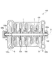
- FIG. 1 is a cross-sectional view of a centrifugal compressor according to an embodiment of the present invention.
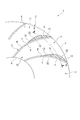
- FIG. 2 is an enlarged front view showing a main part of the impeller in the embodiment of the present invention.
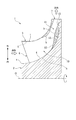
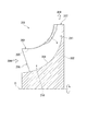
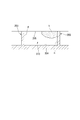
- FIG. 3 is a cross-sectional view taken along line AA in FIG. 4 is a cross-sectional view taken along line BB in FIG.
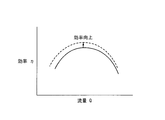
- FIG. 5 is a graph showing efficiency characteristics with respect to the flow rate of the impeller in the embodiment of the present invention.
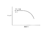
- FIG. 6 is a graph showing the head characteristics with respect to the flow rate of the impeller in the embodiment of the present invention.
- FIG. 7 is a front view of an impeller in another example of the embodiment of the present invention.
- FIG. 8 is a cross-sectional view taken along line B′-B ′ of FIG.
- FIG. 9 is a front view of a conventional impeller corresponding to FIG. 10 is a cross-sectional view taken along line AA in FIG.
- FIG. 11 is a sectional view taken along line BB in FIG.
- the impeller of this embodiment will be described by taking as an example an impeller of a centrifugal compressor that is a rotating machine.
- a centrifugal compressor 100 that is a rotating machine according to the present embodiment mainly includes a shaft 102 that is rotated around an axis O, and a process that uses centrifugal force attached to the shaft 102.
- the impeller 1 that compresses the gas (gas) G
- the casing 105 that supports the shaft 102 rotatably and has a flow path 104 that allows the process gas G to flow from the upstream side to the downstream side are formed.
- the casing 105 is formed so as to form a substantially cylindrical outline, and the shaft 102 is disposed so as to penetrate the center.
- Journal bearings 105a are provided at both ends of the shaft 102 in the axial direction, and thrust bearings 105b are provided at one end.
- the journal bearing 105a and the thrust bearing 105b support the shaft 102 in a rotatable manner. That is, the shaft 102 is supported by the casing 105 via the journal bearing 105a and the thrust bearing 105b.
- a suction port 105c through which the process gas G flows from the outside is provided at one end side in the axial direction of the casing 105, and a discharge port 105d through which the process gas G flows out to the outside is provided at the other end side.
- an internal space that communicates with the suction port 105c and the discharge port 105d, respectively, and repeats the diameter reduction and the diameter expansion is provided.
- This internal space functions as a space for accommodating the impeller 1 and also functions as the flow path 104. That is, the suction port 105 c and the discharge port 105 d communicate with each other via the impeller 1 and the flow path 104.
- a plurality of impellers 1 are arranged at intervals in the axial direction of the shaft 102. In the illustrated example, six impellers 1 are provided, but it is sufficient that at least one impeller 1 is provided.
- the impeller 1 of the centrifugal compressor 100 shows the impeller 1 of the centrifugal compressor 100, and the impeller 1 includes a hub 2 and a plurality of blades 3.
- the hub 2 is formed in a substantially circular shape when viewed from the front, and is rotatable around the axis about the axis O described above.
- a hub surface 4 is curvedly formed on the hub 2 from a predetermined position S on the radially inner side that is slightly spaced radially outward from the axis O toward the radially outer side.
- the curved hub surface 4 is formed such that a surface positioned radially inward is formed along the axis O and gradually along the radial direction toward the radially outer side.
- the hub 2 has an axial thickness dimension that decreases from one of the axial end faces (upstream side) from the radially inner position S slightly spaced from the axis O toward the radially outer side. The size is larger toward the inner side and smaller toward the outer side.
- the radial direction of the hub 2 is indicated by an arrow.
- a plurality of blades 3 are arranged substantially radially on the hub surface 4 described above, and are erected substantially perpendicular to the hub surface 4 as shown in FIG.
- the blade 3 is formed to have a substantially uniform thickness from the hub end h to the tip end t, and in the direction of rotation of the hub 2 (indicated by an arrow in FIG. 2) from the hub end h (see FIG. 3) to the tip end t. It has a curved shape with a slightly convex surface.
- the blade surface on the convex side of the concave blade side and the convex blade surface of the curved blade 3 becomes the pressure surface p, while the blade surface on the concave surface on the back side of the convex surface is negative. It becomes the pressure surface n.
- the tip end t of the blade 3 is curved from the radially inner side to the radially outer side of the hub 2. More specifically, like the hub surface 4 described above, it is formed in a concave shape along the axis O toward the radially inner side and gradually along the radial direction toward the radially outer side.
- the blade 3 is formed such that its height dimension is higher on the inner side in the radial direction of the hub 2 and lower on the outer side in the radial direction with respect to the hub surface 4.
- the tip end t side of the blade 3 is covered with a casing 105 (see FIG. 1), and the shroud surface 5 constituted by the casing 105 and the pressure surface p and negative pressure of the adjacent blade 3 described above.
- the impeller channel 10 of the impeller 1 is configured by the pressure surface n and the hub surface 4 between the pressure surface p and the negative pressure surface n. Then, as the impeller 1 rotates, fluid flows in the axial direction from the inlet 6 of the impeller flow path 10 located on the radially inner side of the hub 2, and from the outlet 7 located on the radially outer side by centrifugal force. The fluid flows outward along the radial direction.
- the impeller channel 10 having the above-described configuration has its flow direction gradually changed from the axial direction to the radial direction from the radially inner side to the radially outer side of the hub 2. Curved formation. Since the impeller channel 10 is curved in this way, a low-energy fluid mass k (FIG. 3, FIG. 3) is formed on the shroud surface 5 side near the negative pressure surface n of the rear half part 11 on the outlet 7 side of the impeller channel 10. 4) is easily accumulated.
- a bulge portion b that bulges toward the inside of the impeller flow path 10 is formed at a corner portion 12 where the hub surface 4 and the negative pressure surface n of the blade 3 are in contact.
- the bulging portion b is formed integrally with the hub surface 4 and the negative pressure surface n (see FIGS. 2 and 4).
- the maximum width of the bulging portion b is set to about 25% of the width of the impeller flow path 10 and about 30% of the height of the blade 3. It is desirable that the maximum width and the maximum height are obtained at a position of about 65% of the flow path length from the inlet 6 to the outlet 7 of the impeller flow path 10.
- a rubbed portion 13 that smoothly connects the hub surface 4 and the negative pressure surface n is provided around the bulging portion b.
- the rubbed portion 13 swells as the width and height gradually increase from the position of about 30% of the channel length toward the outlet 7 side with respect to the negative pressure surface n. It leads to the exit part b. Further, on the outlet 7 side of the bulging portion b, the width and height are gradually reduced in the direction of the outlet 7, and consideration is given to connection to a diffuser (not shown) disposed at the rear stage of the impeller 1 and the like. At the outlet 7, it converges to the suction surface n and the width and height dimensions return to zero.
- the shape and position of the bulging part b mentioned above are examples, and are not restricted to said position, Moreover, the starting position of the rubbed part 13 is not restricted to the said position.
- FIG. 5 is a graph showing the efficiency characteristics of a rotating machine using the impeller 1 and a conventional impeller.
- the vertical axis represents the efficiency ⁇ and the horizontal axis represents the flow rate Q.
- the efficiency of the rotary machine provided with the impeller which is not provided with the bulging part b is shown by a solid line
- the efficiency of the rotary machine provided with the impeller 1 provided with the bulge part b is shown by a broken line.
- the efficiency on the small flow rate side is greatly improved.
- FIG. 6 is a graph showing the head (work) characteristics of the rotary machine using the impeller 1 and the conventional impeller, with the head (work) on the vertical axis and the flow rate Q on the horizontal axis.
- the head of the rotary machine provided with the impeller which is not provided with the bulging part b is shown by a solid line
- the head of the rotary machine provided with the impeller 1 provided with the bulge part b is shown by a broken line.
- the above-described impeller 1 provided with the bulging portion b is more than the surge point (indicated by a filled circle in the drawing) of the rotating machine provided with the impeller not provided with the bulging portion b.
- the surge point (indicated by a white circle in the figure) of the rotating machine provided is displaced to the lower flow rate side and the surge margin is expanded.
- the efficiency improvement and the reduction of the surge point flow rate in FIGS. 5 and 6 reduce the mass k of the low energy fluid in the rear half 11 of the impeller flow path 10 by being pressed against the high energy fluid that has passed over the bulging portion b. This is because the stall of the fluid is suppressed.
- the surge point is a minimum flow rate necessary for the rotating machine to operate normally without surging.
- the bulging portion b is in the impeller flow path from the corner 12 where the hub surface 4 and the negative pressure surface n of the blade 3 are in contact in the rear half portion 11 of the impeller flow path 10.
- the fluid flowing through the impeller channel 10 gets over the bulged portion b in the rear half portion 11. Since the high energy fluid that has passed over the bulge b is pressed against the mass k of the low energy fluid generated on the opposite surface of the bulge b, the mass k of the low energy fluid is reduced, so that the mass k of the low energy fluid accumulates. This can reduce the flow loss. Further, the mass k of the low energy fluid tends to increase as the flow rate decreases.
- the efficiency can be improved particularly when a low flow rate fluid is introduced. Surge margin is also increased because the stall is suppressed. Further, by providing the bulging portion b at the corner portion 12, the strength of the portion where the blade 3 and the hub 2 where the bulging portion b is formed can be increased. Furthermore, the hub 2 and the blade
- the corner portion where the negative pressure surface n and the hub surface 4 are in contact with each other which is relatively close to the portion where the mass k of the low energy fluid is accumulated near the corner portion between the negative pressure surface n of the blade 3 and the shroud surface 5 on the tip end t side. Since the bulging part b is provided in 12, the high-energy fluid that has passed over the bulging part b can be efficiently reduced by pressing the mass k of the low-energy fluid. Furthermore, since the bulging portion b is smoothly connected to the hub surface 4 and the negative pressure surface n by the rubbed portion 13, it is possible to suppress a loss when the high energy fluid gets over the bulging portion b.
- the bulging portion b is provided in the corner 12 where the negative pressure surface n located in the rear half portion 11 of the impeller flow channel 10 and the hub surface 4 are in contact. It is not limited.
- a bulging portion b may be provided at the corner 22 where the pressure surface p located at the rear half 11 of the impeller flow channel 10 and the hub surface 4 are in contact. Good.
- the bulging portion b is overcome by the low energy fluid mass k accumulated near the corner portion of the suction surface n and the shroud surface 5 of the blade 3.
- the rubbed portion 13 is not limited to this.
- the impeller of the centrifugal rotary machine has been described as an example.
- the impeller is not limited to this, and may be an impeller of a mixed flow type rotary machine.
- it is not restricted to a compressor, You may apply to impellers, such as an air blower and a turbine.
- a so-called open type impeller in which the opposite side of the hub surface 4 is covered by the shroud surface 5 has been described as an example.
- a closed type including a wall that covers the tip end t side integrally formed with the blade 3 is provided. It may be applied to the impeller.
- the shroud surface 5 of the above-described embodiment may be read as the inner surface of the wall covering the tip end t.
- the fillet R due to the roundness of the tip of the cutting cutter tool is slightly attached to the boundary portion between the hub surface 4 and the blade surface (negative pressure surface n, pressure surface p) other than the bulging portion b as usual.
- the fluid channel when the bulging portion is provided at the corner where the hub surface and the blade surface are in contact with each other, when the fluid flowing through the fluid channel gets over the bulging portion, the fluid channel
- the mass of the low energy fluid generated along the shroud surface in the vicinity of the suction surface of the latter half of the blade can be reduced, so that the flow loss caused by the expansion of the mass of the low energy fluid can be reduced.
Landscapes
- Engineering & Computer Science (AREA)
- Mechanical Engineering (AREA)
- General Engineering & Computer Science (AREA)
- Structures Of Non-Positive Displacement Pumps (AREA)
Abstract
L'invention concerne une roue disposée dans une machine rotative, dans laquelle la direction d'écoulement passe progressivement de la direction axiale à la direction radiale, l'écoulement s'écoulant simultanément du côté interne dans la direction radiale vers le côté externe dans la direction radiale de conduits de fluide. La roue comprend des surfaces de moyeu qui configurent au moins une partie des conduits de fluide précités ; des surfaces d'aube qui configurent au moins une partie des conduits de fluide précités ; et des parties saillantes qui font saillie vers l'intérieur des conduits de fluide au niveau des angles situés là où les surfaces de moyeu viennent en contact avec les surfaces d'aube au niveau des dernières moitiés, qui sont les dernières moitiés vers les sorties opposées aux premières moitiés vers les entrées des conduits de fluide.
Priority Applications (3)
| Application Number | Priority Date | Filing Date | Title |
|---|---|---|---|
| US13/259,286 US9163642B2 (en) | 2009-07-13 | 2010-02-18 | Impeller and rotary machine |
| CN201080015579.9A CN102365463B (zh) | 2009-07-13 | 2010-02-18 | 叶轮及旋转机械 |
| EP10799531.8A EP2402616A4 (fr) | 2009-07-13 | 2010-02-18 | Roue et machine rotative |
Applications Claiming Priority (2)
| Application Number | Priority Date | Filing Date | Title |
|---|---|---|---|
| JP2009-164781 | 2009-07-13 | ||
| JP2009164781A JP2011021491A (ja) | 2009-07-13 | 2009-07-13 | インペラおよび回転機械 |
Publications (1)
| Publication Number | Publication Date |
|---|---|
| WO2011007467A1 true WO2011007467A1 (fr) | 2011-01-20 |
Family
ID=43449080
Family Applications (1)
| Application Number | Title | Priority Date | Filing Date |
|---|---|---|---|
| PCT/JP2010/001056 Ceased WO2011007467A1 (fr) | 2009-07-13 | 2010-02-18 | Roue et machine rotative |
Country Status (5)
| Country | Link |
|---|---|
| US (1) | US9163642B2 (fr) |
| EP (1) | EP2402616A4 (fr) |
| JP (1) | JP2011021491A (fr) |
| CN (1) | CN102365463B (fr) |
| WO (1) | WO2011007467A1 (fr) |
Families Citing this family (23)
| Publication number | Priority date | Publication date | Assignee | Title |
|---|---|---|---|---|
| US8998582B2 (en) * | 2010-11-15 | 2015-04-07 | Sundyne, Llc | Flow vector control for high speed centrifugal pumps |
| JP6064310B2 (ja) * | 2011-06-10 | 2017-01-25 | 株式会社Ihi | タービン及び車両用過給機 |
| DE102012106810B4 (de) * | 2012-07-26 | 2020-08-27 | Ihi Charging Systems International Gmbh | Laufrad für eine Fluidenergiemaschine |
| US9707369B2 (en) | 2013-06-28 | 2017-07-18 | Vyaire Medical Capital Llc | Modular flow cassette |
| US9433743B2 (en) | 2013-06-28 | 2016-09-06 | Carefusion 303, Inc. | Ventilator exhalation flow valve |
| US9962514B2 (en) | 2013-06-28 | 2018-05-08 | Vyaire Medical Capital Llc | Ventilator flow valve |
| US9795757B2 (en) | 2013-06-28 | 2017-10-24 | Vyaire Medical Capital Llc | Fluid inlet adapter |
| CN104251231A (zh) * | 2013-06-28 | 2014-12-31 | 苏州宝时得电动工具有限公司 | 离心式叶轮及包括该离心式叶轮的吹吸装置 |
| US9541098B2 (en) * | 2013-06-28 | 2017-01-10 | Vyaire Medical Capital Llc | Low-noise blower |
| US9746359B2 (en) | 2013-06-28 | 2017-08-29 | Vyaire Medical Capital Llc | Flow sensor |
| JP5705945B1 (ja) * | 2013-10-28 | 2015-04-22 | ミネベア株式会社 | 遠心式ファン |
| DE102015214854A1 (de) * | 2015-08-04 | 2017-02-09 | Bosch Mahle Turbo Systems Gmbh & Co. Kg | Verdichterrad für einen Abgasturbolader |
| CN106382255A (zh) * | 2016-11-23 | 2017-02-08 | 广东威灵电机制造有限公司 | 叶轮 |
| CN106382254A (zh) * | 2016-11-23 | 2017-02-08 | 广东威灵电机制造有限公司 | 叶轮 |
| JP6988215B2 (ja) * | 2017-07-12 | 2022-01-05 | 株式会社Ihi | 遠心圧縮機インペラ及び遠心圧縮機 |
| US10962021B2 (en) * | 2018-08-17 | 2021-03-30 | Rolls-Royce Corporation | Non-axisymmetric impeller hub flowpath |
| US11181123B2 (en) * | 2019-03-22 | 2021-11-23 | Apergy Esp Systems, Llc | Downhole centrifugal pump diffuser with protuberant vanes |
| US11952875B2 (en) * | 2019-10-25 | 2024-04-09 | Schlumberger Technology Corporation | Non-axisymmetric hub and shroud profile for electric submersible pump stage |
| CN110725808B (zh) * | 2019-10-31 | 2021-03-02 | 中国科学院工程热物理研究所 | 离心叶轮叶片及构型方法与离心压气机 |
| JP7591871B2 (ja) | 2020-03-27 | 2024-11-29 | 三菱重工コンプレッサ株式会社 | 遠心圧縮機用のインペラ、及び遠心圧縮機 |
| CN112648232A (zh) * | 2021-01-11 | 2021-04-13 | 泛仕达机电股份有限公司 | 一种具有错列叶片的后向离心风机叶片及后向离心风机 |
| DE102021133772B3 (de) | 2021-12-18 | 2023-01-19 | Borgwarner Inc. | Verdichterrad |
| CN115289062A (zh) * | 2022-08-25 | 2022-11-04 | 华帝股份有限公司 | 叶轮及具有其的离心风机 |
Citations (6)
| Publication number | Priority date | Publication date | Assignee | Title |
|---|---|---|---|---|
| JP2005163640A (ja) | 2003-12-03 | 2005-06-23 | Mitsubishi Heavy Ind Ltd | 圧縮機のインペラ |
| JP2005180372A (ja) | 2003-12-22 | 2005-07-07 | Mitsubishi Heavy Ind Ltd | 圧縮機のインペラ |
| JP2006002689A (ja) | 2004-06-18 | 2006-01-05 | Hitachi Home & Life Solutions Inc | 送風機 |
| JP2006077723A (ja) * | 2004-09-13 | 2006-03-23 | Matsushita Electric Ind Co Ltd | 多翼ファン |
| JP2007192034A (ja) * | 2006-01-17 | 2007-08-02 | Matsushita Electric Ind Co Ltd | 電動送風機及びそれを用いた電気掃除機 |
| JP2009164781A (ja) | 2007-12-28 | 2009-07-23 | Pioneer Electronic Corp | 電話機 |
Family Cites Families (4)
| Publication number | Priority date | Publication date | Assignee | Title |
|---|---|---|---|---|
| US2918254A (en) * | 1954-05-10 | 1959-12-22 | Hausammann Werner | Turborunner |
| EP1290236B1 (fr) * | 2000-04-28 | 2009-11-04 | Elliott Company | Procede de soudage, composition de metal d'apport et article fabrique a partir de ladite composition |
| JP2003013895A (ja) | 2001-06-27 | 2003-01-15 | Mitsubishi Heavy Ind Ltd | 遠心圧縮機 |
| CN1278046C (zh) * | 2002-11-15 | 2006-10-04 | 乐金电子(天津)电器有限公司 | 涡轮风扇 |
-
2009
- 2009-07-13 JP JP2009164781A patent/JP2011021491A/ja not_active Withdrawn
-
2010
- 2010-02-18 CN CN201080015579.9A patent/CN102365463B/zh not_active Expired - Fee Related
- 2010-02-18 WO PCT/JP2010/001056 patent/WO2011007467A1/fr not_active Ceased
- 2010-02-18 EP EP10799531.8A patent/EP2402616A4/fr not_active Withdrawn
- 2010-02-18 US US13/259,286 patent/US9163642B2/en not_active Expired - Fee Related
Patent Citations (6)
| Publication number | Priority date | Publication date | Assignee | Title |
|---|---|---|---|---|
| JP2005163640A (ja) | 2003-12-03 | 2005-06-23 | Mitsubishi Heavy Ind Ltd | 圧縮機のインペラ |
| JP2005180372A (ja) | 2003-12-22 | 2005-07-07 | Mitsubishi Heavy Ind Ltd | 圧縮機のインペラ |
| JP2006002689A (ja) | 2004-06-18 | 2006-01-05 | Hitachi Home & Life Solutions Inc | 送風機 |
| JP2006077723A (ja) * | 2004-09-13 | 2006-03-23 | Matsushita Electric Ind Co Ltd | 多翼ファン |
| JP2007192034A (ja) * | 2006-01-17 | 2007-08-02 | Matsushita Electric Ind Co Ltd | 電動送風機及びそれを用いた電気掃除機 |
| JP2009164781A (ja) | 2007-12-28 | 2009-07-23 | Pioneer Electronic Corp | 電話機 |
Also Published As
| Publication number | Publication date |
|---|---|
| US20120100003A1 (en) | 2012-04-26 |
| EP2402616A4 (fr) | 2018-02-28 |
| JP2011021491A (ja) | 2011-02-03 |
| US9163642B2 (en) | 2015-10-20 |
| CN102365463B (zh) | 2014-07-16 |
| EP2402616A1 (fr) | 2012-01-04 |
| CN102365463A (zh) | 2012-02-29 |
Similar Documents
| Publication | Publication Date | Title |
|---|---|---|
| WO2011007467A1 (fr) | Roue et machine rotative | |
| CN102365464B (zh) | 叶轮和旋转机械 | |
| CN104105886B (zh) | 回转机械 | |
| JPWO2010047259A1 (ja) | ラジアルタービンのスクロール構造 | |
| WO2014115417A1 (fr) | Machine à rotation centrifuge | |
| JP5029024B2 (ja) | 遠心圧縮機 | |
| JP2009133267A (ja) | 圧縮機のインペラ | |
| WO2015053051A1 (fr) | Roue et machine tournante munie de ladite roue | |
| JP2018173020A (ja) | 遠心圧縮機 | |
| WO2019172422A1 (fr) | Aube de diffuseur et compresseur centrifuge | |
| JP6763804B2 (ja) | 遠心圧縮機 | |
| JP2019007425A (ja) | 遠心圧縮機、ターボチャージャ | |
| WO2018155458A1 (fr) | Machine rotative centrifuge | |
| WO2014122819A1 (fr) | Compresseur centrifuge | |
| JP2021011828A (ja) | 多段遠心圧縮機 | |
| WO2025238941A1 (fr) | Compresseur centrifuge | |
| JP6265000B2 (ja) | 遠心圧縮機 | |
| JPWO2018179173A1 (ja) | インペラ及び遠心圧縮機 | |
| CN110234888B (zh) | 压缩机的涡旋形状以及增压器 | |
| JP6935312B2 (ja) | 多段遠心圧縮機 | |
| JP2017057779A (ja) | ターボチャージャ | |
| JP6768172B1 (ja) | 遠心圧縮機 | |
| JP2022151994A (ja) | 回転機械 | |
| JP2020197132A (ja) | 回転機械 | |
| WO2017170285A1 (fr) | Roue centrifuge et machine à fluide centrifuge équipée de celle-ci |
Legal Events
| Date | Code | Title | Description |
|---|---|---|---|
| WWE | Wipo information: entry into national phase |
Ref document number: 201080015579.9 Country of ref document: CN |
|
| 121 | Ep: the epo has been informed by wipo that ep was designated in this application |
Ref document number: 10799531 Country of ref document: EP Kind code of ref document: A1 |
|
| WWE | Wipo information: entry into national phase |
Ref document number: 13259286 Country of ref document: US |
|
| WWE | Wipo information: entry into national phase |
Ref document number: 2010799531 Country of ref document: EP |
|
| NENP | Non-entry into the national phase |
Ref country code: DE |