WO2011007617A1 - ガラス板の製造方法及び製造装置 - Google Patents
ガラス板の製造方法及び製造装置 Download PDFInfo
- Publication number
- WO2011007617A1 WO2011007617A1 PCT/JP2010/058670 JP2010058670W WO2011007617A1 WO 2011007617 A1 WO2011007617 A1 WO 2011007617A1 JP 2010058670 W JP2010058670 W JP 2010058670W WO 2011007617 A1 WO2011007617 A1 WO 2011007617A1
- Authority
- WO
- WIPO (PCT)
- Prior art keywords
- molding chamber
- opening
- glass ribbon
- width direction
- glass
- Prior art date
- Legal status (The legal status is an assumption and is not a legal conclusion. Google has not performed a legal analysis and makes no representation as to the accuracy of the status listed.)
- Ceased
Links
Images
Classifications
-
- C—CHEMISTRY; METALLURGY
- C03—GLASS; MINERAL OR SLAG WOOL
- C03B—MANUFACTURE, SHAPING, OR SUPPLEMENTARY PROCESSES
- C03B17/00—Forming molten glass by flowing-out, pushing-out, extruding or drawing downwardly or laterally from forming slits or by overflowing over lips
- C03B17/06—Forming glass sheets
- C03B17/064—Forming glass sheets by the overflow downdraw fusion process; Isopipes therefor
-
- C—CHEMISTRY; METALLURGY
- C03—GLASS; MINERAL OR SLAG WOOL
- C03B—MANUFACTURE, SHAPING, OR SUPPLEMENTARY PROCESSES
- C03B17/00—Forming molten glass by flowing-out, pushing-out, extruding or drawing downwardly or laterally from forming slits or by overflowing over lips
- C03B17/06—Forming glass sheets
- C03B17/067—Forming glass sheets combined with thermal conditioning of the sheets
-
- C—CHEMISTRY; METALLURGY
- C03—GLASS; MINERAL OR SLAG WOOL
- C03B—MANUFACTURE, SHAPING, OR SUPPLEMENTARY PROCESSES
- C03B17/00—Forming molten glass by flowing-out, pushing-out, extruding or drawing downwardly or laterally from forming slits or by overflowing over lips
- C03B17/06—Forming glass sheets
- C03B17/068—Means for providing the drawing force, e.g. traction or draw rollers
-
- C—CHEMISTRY; METALLURGY
- C03—GLASS; MINERAL OR SLAG WOOL
- C03B—MANUFACTURE, SHAPING, OR SUPPLEMENTARY PROCESSES
- C03B18/00—Shaping glass in contact with the surface of a liquid
- C03B18/02—Forming sheets
- C03B18/04—Changing or regulating the dimensions of the molten glass ribbon
- C03B18/06—Changing or regulating the dimensions of the molten glass ribbon using mechanical means, e.g. restrictor bars, edge rollers
-
- C—CHEMISTRY; METALLURGY
- C03—GLASS; MINERAL OR SLAG WOOL
- C03B—MANUFACTURE, SHAPING, OR SUPPLEMENTARY PROCESSES
- C03B33/00—Severing cooled glass
- C03B33/02—Cutting or splitting sheet glass or ribbons; Apparatus or machines therefor
- C03B33/0215—Cutting or splitting sheet glass or ribbons; Apparatus or machines therefor the ribbon being in a substantially vertical plane
Definitions
- the present invention relates to a glass plate manufacturing method and manufacturing apparatus.
- a method called a fusion method has been known as a method for producing a high-quality glass plate.
- molten glass is allowed to flow down along both side surfaces of a wedge-shaped molded body that converges downward, and these molten glasses are merged and integrated directly below the lower edge of the molded body.
- This is a method of forming a plate-like glass ribbon to a target thickness by pulling downward while cooling.
- a partition is provided immediately below the molded body, and the two partition walls can be formed from both sides of the glass ribbon to the glass ribbon as much as possible.
- a technique for arranging them so as to approach each other is known (for example, see Patent Documents 1 and 2).
- This invention was made in view of the said subject, Comprising: It aims at providing the manufacturing method and manufacturing apparatus of a glass plate which can manufacture a high quality glass plate easily.
- the present invention provides: The molten glass is allowed to flow down along both side surfaces of the molded body in the molding chamber, and the molten glass is merged and integrated just below the lower edge of the molded body, and the integrated plate-like glass ribbon is opened from the molding chamber opening.
- the thickness of the center in the width direction of the glass ribbon passing through the molding chamber opening is set to 1.0 mm or less
- the gap in the direction perpendicular to the vertical plane between the molding chamber opening and the vertical plane including the lower edge of the molded body is set to 8 mm or more and 70 mm or less
- a gap between a side surface portion on the width direction side of the glass ribbon of the forming chamber opening and each end portion in the width direction of the glass ribbon passing through the forming chamber opening is set to 10 mm or more and 500 mm or less.
- the present invention also provides: A molded body that merges and integrates the molten glass that has flowed down along both side surfaces directly under the lower edge, and A molding chamber in which the molded body is disposed; In a glass plate manufacturing apparatus having a molding chamber opening for drawing a plate-shaped glass ribbon integrated by the molded body downward from the molding chamber, Viscosity ratio (V 2 / V 1 ) between the viscosity (V 1 ) at the center in the width direction of the molten glass at the upper edge of the molded body and the viscosity (V 2 ) at the center in the width direction of the glass ribbon passing through the molding chamber opening.
- the thickness of the center in the width direction of the glass ribbon passing through the molding chamber opening is set to 1.0 mm or less
- the gap in the direction perpendicular to the vertical plane between the molding chamber opening and the vertical plane including the lower edge of the molded body is set to 8 mm or more and 70 mm or less
- a gap between a side surface portion on the width direction side of the glass ribbon of the molding chamber opening and each end portion in the width direction of the glass ribbon passing through the molding chamber opening is set to 10 mm or more and 500 mm or less.
- the present invention it is possible to provide a glass plate manufacturing method and a manufacturing apparatus capable of easily manufacturing a high-quality glass plate.
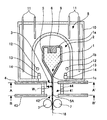
- FIG. 1 is a partial cross-sectional view showing an example of the glass plate manufacturing apparatus of the present invention.
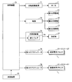
- FIG. 2 is a functional block diagram showing a control system of the glass plate manufacturing apparatus of FIG.
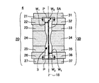
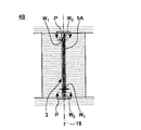
- FIG. 3 is a cross-sectional view taken along the line AA ′ of FIG. 1 and shows the molding chamber opening 3.
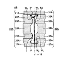
- FIG. 4 is a cross-sectional view showing a modification of FIG.
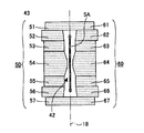
- FIG. 5 is a cross-sectional view taken along the line BB ′ of FIG. 1 and showing the communication chamber opening 42.
- FIG. 6 is a cross-sectional view showing a comparative example corresponding to FIG.
- FIG. 1 is a partial cross-sectional view showing a glass plate manufacturing apparatus according to an embodiment of the present invention.
- FIG. 2 is a functional block diagram showing a control system of the glass plate manufacturing apparatus of FIG.
- the glass plate manufacturing apparatus includes a molded body 1 that merges and integrates molten glass that has flowed down along both side surfaces just below the lower edge of the molded body 1, and a molded body 1 inside. Is formed, and a molding chamber opening 3 for drawing a plate-like glass ribbon integrated by the molded body 1 downward from the molding chamber 2 is provided.
- the molding chamber opening 3 is constituted by a first opening member 4.
- the molded body 1 is made of a refractory material such as alumina or zirconia.
- the molded body 1 has a wedge-shaped cross section that converges downward.
- a recess 6 is formed in the upper part of the molded body 1.
- a molten glass supply pipe (not shown) is connected to the recess 6 of the molded body 1.
- the molten glass 5 supplied from the molten glass supply pipe into the recess 6 overflows from the upper edge of the recess 6 (that is, the upper edge of the molded body 1) 1a, flows down along both side surfaces of the molded body 1, and is molded. It merges directly under the lower edge 1b of the body 1.
- the joined molten glass 5 becomes a plate-like glass ribbon 5A.
- the glass ribbon 5 ⁇ / b> A is formed by being drawn downward by a pair of rollers 7 that are rotationally driven by a rotational drive device 71.
- a pair of rollers 7 is provided, but a plurality of sets may be provided.
- the formed glass ribbon 5A is cut off at both ends in the width direction, and the remaining central portion in the width direction is provided as a glass plate as a product.
- the molding chamber 2 is installed inside the furnace chamber 8.
- the molding chamber 2 and the furnace chamber 8 are partitioned by a partition wall 9.
- the partition wall 9 is placed and fixed on the floor surface of the furnace wall 10 that forms the furnace chamber 8.
- the partition wall 9 and the furnace wall 10 are made of a refractory material.
- a plurality of first heating elements 11 are installed inside in order to prevent the molten glass 5 and the glass ribbon 5 ⁇ / b> A from being cooled.
- Each first heating element 11 is connected to a power source 72.
- the amount of power supplied from the power source 72 to each first heating element 11 is individually controlled by the control device 73. Thereby, the temperature of the molten glass 5 and the glass ribbon 5A can be adjusted.
- the molding chamber 2 has a second heating element for controlling the temperature distribution in the vertical direction and the width direction of the molten glass 5 and the glass ribbon 5A. 12, a third heating element 13 and a cooling body 14 are installed.
- the second heating elements 12 are arranged on both sides of the molded body 1, and a plurality of the second heating elements 12 are arranged in each direction in a direction parallel to the width direction of the molten glass 5.
- Each second heating element 12 is connected to a power source 72.
- the amount of power supplied from the power source 72 to each second heating element 12 is individually controlled by the control device 73. Thereby, the temperature distribution of the up-down direction and the width direction of the molten glass 5 or the glass ribbon 5A can be adjusted.
- the third heating elements 13 are arranged on both sides in the vicinity of the lower edge 1b of the molded body 1, and a plurality of third heating elements 13 are arranged in each direction in a direction parallel to the width direction of the molten glass 5.
- Each third heating element 13 is connected to a power source 72.
- the amount of power supplied from the power source 72 to each third heating element 13 is individually controlled by the control device 73. Thereby, the temperature distribution of the up-down direction and the width direction of the molten glass 5 or the glass ribbon 5A can be adjusted.
- the cooling bodies 14 are arranged on both sides in the vicinity of the lower edge 1b of the molded body 1, and a plurality of cooling bodies 14 are arranged in each direction in a direction parallel to the width direction of the molten glass 5.
- Each cooling body 14 is connected to a refrigerant supply pipe 75 whose opening degree can be adjusted by a throttle valve 74.
- the amount of refrigerant supplied from the refrigerant supply rod 75 to each cooling body 14 is individually controlled by the control device 73. Thereby, the temperature distribution of the up-down direction and the width direction of the molten glass 5 or the glass ribbon 5A can be adjusted.
- FIG. 3 is a cross-sectional view of the forming chamber opening 3 taken along the line AA ′ of FIG.
- FIG. 4 is a cross-sectional view showing a modification of FIG.
- the molding chamber opening 3 is provided immediately below the molded body 1.
- the molding chamber opening 3 extends in the width direction of the glass ribbon 5A.
- the shape dimension of the molding chamber opening 3 is set larger than the shape dimension of the cross section of the glass ribbon 5A so that the first opening member 4 and the glass ribbon 5A do not come into contact with each other.
- the glass ribbon 5A passing through the molding chamber opening 3 has a thickness at the center in the width direction of 1.0 mm or less.
- Gap W 1 is set below 70mm or 8 mm, more preferably, it is set to 10mm or 60mm or less.
- the gap W 1, as long as it is set within the above range may be changed to a width direction of the glass ribbon 5A, may be constant.
- the gap W 1, as long as it is set within the above range, the longitudinal direction may be changed to a (vertical direction in FIG. 1) of the glass ribbon 5A, it may be constant.
- the gap W 1 is set smaller than 8 mm, the heat transfer between the molding chamber 2 and the lower forming chamber 2 is suppressed, becomes the temperature of the forming chamber 2 is likely to be more than the desired temperature, the forming chamber 2 A large temperature difference occurs between the lower part of the molding chamber 2 (that is, the upper part and the lower part with the first opening member 4 as a boundary). Therefore, a rapid temperature change occurs at the boundary between the molding chamber 2 and the lower side of the molding chamber 2 (that is, near the molding chamber opening 3). For this reason, since it becomes difficult to control the temperature distribution at the boundary portion, the glass ribbon 5A is cut with a narrow width due to its own weight or a downward pulling force, and it becomes difficult to continuously and stably produce a glass plate. Alternatively, even if the glass ribbon 5A is not cut, the thickness of the glass plate to be manufactured may be uneven or warped.
- the gap W 1 greater than 70 mm, the heat transfer between the molding chamber 2 and the lower forming chamber 2 is accelerated, the temperature of the forming chamber 2 is likely to be below the desired temperature. As a result, the viscosity of the glass ribbon 5A increases, and the glass ribbon 5A may be cut without being stretched thinly.
- the above problem is seen when a thin glass plate having a thickness of 1.0 mm or less is produced, and particularly when a thin glass plate having a thickness of 0.3 mm or less is produced.
- the viscosity ratio V 2 / V 1 with 2 is set to 20 to 50,000.
- the glass ribbon 5A When the viscosity ratio V 2 / V 1 is set to be smaller than 20, the glass ribbon 5A may be cut due to its own weight or a downward pulling force, and the thickness may be non-uniform even if not cut. There is a fear. When the viscosity ratio V 2 / V 1 is set to be larger than 50000, the glass ribbon 5A may be cut without being stretched thinly.
- Gap W 2 is set to 10mm or more 500mm or less.
- the gap W 2 is set to be smaller than 10 mm, the heat transfer suppressing between the forming chamber 2 and the lower forming chamber 2, the temperature of the vicinity of the end portion of the glass ribbon 5A of the forming chamber 2 is more than the desired temperature It becomes easy to become. Further, by setting the gap W 2 larger than 500 mm, the heat transfer between the molding chamber 2 and the lower forming chamber 2 is accelerated, the temperature of the vicinity of the end portion of the glass ribbon 5A of the forming chamber 2 the desired temperature It becomes easy to become below. Accordingly, in either case, the temperature difference between the center and the end of the glass ribbon 5A in the width direction becomes large.
- the glass ribbon 5A becomes too thin or the glass ribbon 5A is warped too much, the glass ribbon 5A is cut, making it difficult to produce a glass plate continuously and stably.
- the thickness of the glass plate to be manufactured may be uneven or warped.
- the first opening member 4 is preferably formed of a material having a heat transfer resistance of 0.001 m 2 K / W or more at the use temperature.
- a ceramic fiber plate is used for the first opening member 4.
- the first opening member 4 may be, for example, a plate shape as shown in FIG. 1 or a block shape, and the shape thereof is not limited.
- the first opening member 4 is provided substantially horizontally immediately below the furnace wall 10, and roughly includes two partition wall members 20 and 30.
- the two partition members 20 and 30 are arrange
- a gap formed by the two partition members 20, 30 serves as a molding chamber opening 3 for passing the glass ribbon 5 ⁇ / b> A below the molding chamber 2.
- the partition member 20 is preferably divided into a plurality of molding chamber blocks 21 to 27 in the width direction of the glass ribbon 5A.
- the partition member 20 is preferably composed of a plurality of molding chamber blocks 21 to 27 arranged in a direction parallel to the width direction of the glass ribbon 5A.
- the partition member 30 is preferably divided into a plurality of molding chamber blocks 31 to 37 in the width direction of the glass ribbon 5A.
- the partition member 30 is preferably composed of a plurality of molding chamber blocks 31 to 37 arranged in a direction parallel to the width direction of the glass ribbon 5A. Note that the number of divisions of the one partition wall member 20 and the number of divisions of the other partition wall member 30 may be the same or different.
- the dividing surfaces of the molding chamber blocks 21 to 27 and 31 to 37 are perpendicular to the width direction of the glass ribbon 5A.
- the divided surfaces of the molding chamber blocks 21 to 27 and 31 to 37 are perpendicular to the width direction of the glass ribbon 5A, but may be inclined to the width direction of the glass ribbon 5A. Good.
- each of the molding chamber blocks 21 to 27 and 31 to 37 facing the vertical surface 18 may be parallel to the vertical surface 18 or non-parallel.
- Each of the molding chamber blocks 21 to 27 and 31 to 37 is configured to be movable in the direction of approaching and separating from the vertical surface 18 manually or by the first actuator 76.
- each of the molding chamber blocks 21 to 27 and 31 to 37 can be replaced manually or by the first actuator 76 without stopping the supply of the molten glass 5 to the molded body 1. If the supply of the molten glass 5 to the molded body 1 is stopped at the time of replacement, the production of the glass plate is stopped for a long time.
- the shape dimension of the molding chamber opening 3 is adjusted by moving one or a plurality of molding chamber blocks 22 to 26 in the middle of the partition wall member 20 in a direction approaching or separating from the vertical surface 18. be able to.
- the shape dimension of the molding chamber opening 3 can be adjusted by moving one or more molding chamber blocks 32 to 36 in the middle of the partition wall member 30 in a direction approaching or separating from the vertical surface 18. Further, the shape dimension of the molding chamber opening 3 can be changed by replacing one or a plurality of molding chamber blocks 22 to 26 and 32 to 36.
- one molding chamber block 22 to 26 and 32 to 36 is replaced with one molding chamber.
- the blocks 22A to 26A and 32A to 36A may be replaced, or a plurality of adjacent molding chamber blocks may be replaced with one molding chamber block.
- the gap W 1 between the molding chamber opening 3 and the vertical surface 18 can be adjusted or changed.
- the heat transfer between the lower part and the lower part can be adjusted.
- the molding chamber blocks 22 to 26 in the middle of the partition wall member 20 may be further divided in the vertical direction in FIG.
- the molding chamber blocks 32 to 36 in the middle of the partition member 30 may be further divided in the vertical direction in FIG.
- the shape and material of the molded body 1, the shape and material of the partition wall 9 and the furnace wall 10, each heating element, etc. are optimized so that the viscosity distribution (and hence the shape dimension) of the molten glass 5 and the glass ribbon 5A is optimized.
- the shape and arrangement are optimized. However, for example, when the molded body 1 is partially deteriorated by the molten glass 5, the wettability between the molded body 1 and the molten glass 5 is partially changed, so that the molten glass 5 flowing down on both sides of the molded body 1 The thickness changes partially.
- the partition wall 9, the furnace wall 10, the heating element 11 and the like are partially deteriorated, the temperature distribution in the molding chamber 2 is partially changed, so that the viscosity distribution of the molten glass 5 and the glass ribbon 5A is partially changed. Then, the shape dimensions of the molten glass 5 and the glass ribbon 5A partially change.
- the shape and size of the molten glass 5 and the glass ribbon 5A may change due to deterioration with time of components constituting the glass plate manufacturing apparatus. This tendency is observed when a thin glass plate having a thickness of 1.0 mm or less is produced, and particularly when a thin glass plate having a thickness of 0.3 mm or less is produced.
- the viscosity distribution of the molten glass 5 and the glass ribbon 5A can be controlled by moving or replacing one or a plurality of molding chamber blocks 22 to 26, 32 to 36.
- the shape dimensions of the molten glass 5 and the glass ribbon 5A can be corrected. Thereby, it is possible to cope with deterioration with time of components constituting the glass plate manufacturing apparatus.
- the shape dimension of the molding chamber opening 3 is adjusted or changed based on, for example, the shape dimension of the already manufactured glass plate so that the glass plate to be manufactured will have a desired shape dimension.
- the shape dimension of the already produced glass plate is measured by a measuring device 77 (see FIG. 2).
- the measuring device 77 may be connected to the control device 73 as shown in FIG. In this case, when the control device 73 receives the measurement result from the measurement device 77, the control device 73 controls the first actuator 76 so that the glass plate to be manufactured will have a desired shape and dimension, and one or a plurality of molding chamber blocks. Move or exchange 22-26, 32-36. Thereby, the shape dimension of the molding chamber opening 3 is adjusted or changed.
- the pair of molding chamber blocks 24 and 34 in the center of the partition members 20 and 30 are respectively placed on the vertical surface 18. It moves to the direction which leaves
- the gap W 1 from the side to the center in the width direction of the glass ribbon 5A of the forming chamber opening 3 is increased, so much amount of heat transfer between the molding chamber 2 and the lower forming chamber 2.
- the temperature is lowered and the viscosity is increased at the center in the width direction of the glass ribbon 5A passing through the molding chamber opening 3, so that the thickness is increased. Therefore, the thickness at the center in the width direction of the glass plate to be manufactured can be set to the target value.
- the manufactured glass plate is warped, for example, by changing from the first opening member 4 shown in FIG. 3 to the first opening member 4A shown in FIG. And adjust the heat transfer to the desired state. Thereby, the curvature of the glass plate manufactured may be suppressed.
- the shape dimension of the molding chamber opening 3 is adjusted or changed based on the shape dimension of the manufactured glass plate, but the present invention is not limited to this.
- the temperature distribution in the molding chamber 2 or the temperature distribution in the molding chamber opening 3 may be used instead of the shape and size of the manufactured glass plate.
- the temperature distribution in the molding chamber 2 and the temperature distribution in the molding chamber opening 3 are measured by a temperature sensor (not shown) such as a thermocouple provided in the molding chamber 2 or the molding chamber opening 3.
- the geometry of the forming chamber opening 3, for example, as shown in FIG. 3, at least a part of the gap W 1 is adjusted or altered to vary the width direction of the glass ribbon 5A are preferred.
- the heat transfer between the molding chamber 2 and the lower side of the molding chamber 2 changes in the width direction of the glass ribbon 5A
- the viscosity distribution in the width direction of the glass ribbon 5A changes. Therefore, the shape dimension in the width direction of the glass ribbon 5A can be optimized. Thereby, it is possible to cope with deterioration with time of components constituting the glass plate manufacturing apparatus.
- the molding chamber opening 3 is used when the glass plate manufacturing apparatus is started up (that is, when the molten glass 5 is not flowing down along both side surfaces of the molded body 1 and when the molded body 1 is heated). It may be configured to be substantially occluded by a plurality of molding chamber blocks. When the molding chamber opening 3 is substantially closed, heat transfer between the molding chamber 2 and the lower portion of the molding chamber 2 is prevented. Therefore, when the molded body 1 is heated, the temperature distribution in the vertical direction of the molded body 1 is increased. Can be easily made uniform, and damage to the molded body 1 due to thermal stress can be suppressed.
- the partition member 20 is used to pass the glass ribbon 5A below the molding chamber 2.
- the intermediate molding chamber blocks 22 to 26 and 32 to 36 are moved to open the molding chamber opening 3.
- the glass plate manufacturing apparatus further includes a communication chamber 41 communicating with the molding chamber 2 via the molding chamber opening 3 and a communication chamber opening 42 for drawing the glass ribbon 5A downward from the communication chamber 41.
- the communication chamber opening 42 is formed by the second opening member 43.
- the communication chamber 41 is provided below the molding chamber 2 and is surrounded by a cylindrical wall 44.
- the cylinder wall 44 is comprised with the refractory material and the heat insulating material.
- a heating element or a cooling body (not shown) may be installed on the cylindrical wall 44.
- the heating element is connected to the power source 72, and the power supply amount from the power source 72 to the heating element is controlled by the control device 73.
- the cooling body 14 is connected to a refrigerant supply pipe 75 whose opening degree can be adjusted by a throttle valve, and the amount of refrigerant supplied from the refrigerant supply pipe 75 to the cooling body 14 is controlled by the control device 73.
- the temperature of the glass ribbon 5A passing through the communication chamber 41 can be adjusted.
- the temperature of the glass ribbon 5 ⁇ / b> A passing through the molding chamber 2 can be adjusted by the heat transfer between the molding chamber 2 and the communication chamber 41.
- FIG. 5 is a cross-sectional view of the communication chamber opening 42 as viewed from the communication chamber side along the line BB ′ in FIG.
- the shape dimension of the communication chamber opening 42 is set larger than the cross-sectional shape of the glass ribbon 5A so that the second opening member 43 and the glass ribbon 5A do not come into contact with each other.
- the gap in the direction perpendicular to the vertical surface 18 between the communication chamber opening 42 and the vertical surface 18 including the lower edge 1c of the molded body 1 may be changed in the width direction of the glass ribbon 5A or may be constant. May be. Moreover, it may change to the longitudinal direction (up-down direction in FIG. 1) of the glass ribbon 5A, and may be constant.
- the communication chamber opening 42 is formed in the second opening member 43.
- the second opening member 43 is preferably formed of a material having a heat transfer resistance of 0.001 m 2 K / W or more at the use temperature.
- a ceramic fiber plate is used for the second opening member 43.
- the second opening member 43 may be, for example, a plate shape as shown in FIG. 1 or a block shape, and the shape thereof is not limited.
- the second opening member 43 is provided substantially horizontally immediately below the cylindrical wall 44, and is roughly constituted by two partition members 50 and 60.
- the two partition members 50 and 60 are disposed so as to sandwich the vertical surface 18.
- a gap formed by the two partition members 50, 60 serves as a communication chamber opening 42 for allowing the glass ribbon 5 ⁇ / b> A to pass below the communication chamber 41.
- the configuration of the second opening member 43 may be the same as or different from the configuration of the first opening member 4 in which the molding chamber opening 3 is formed.
- the partition member 50 is preferably divided into a plurality of communication chamber blocks 51 to 57 in the width direction of the glass ribbon 5A.
- the partition wall member 50 is preferably composed of a plurality of communication chamber blocks 51 to 57 arranged in a direction parallel to the width direction of the glass ribbon 5A.
- the partition wall member 60 is preferably divided into a plurality of communication chamber blocks 61 to 67 in the width direction of the glass ribbon 5A.
- the partition wall member 60 is preferably composed of a plurality of communication chamber blocks 61 to 67 arranged in a direction parallel to the width direction of the glass ribbon 5A. Note that the number of divisions of one partition wall member 50 and the number of divisions of the other partition wall member 60 may be the same or different.
- the dividing surfaces of the communication chamber blocks 51 to 57 and 61 to 67 are perpendicular to the width direction of the glass ribbon 5A.
- the dividing surfaces of the communication chamber blocks 51 to 57 and 61 to 67 are perpendicular to the width direction of the glass ribbon 5A, but may be inclined to the width direction of the glass ribbon 5A. Good.
- each of the molding chamber blocks 51 to 57 and 61 to 67 facing the vertical surface 18 may be parallel to the vertical surface 18 or non-parallel.
- Each of the communication chamber blocks 51 to 57 and 61 to 67 is configured to be movable in the direction of approaching and separating from the vertical surface 18 manually or by the second actuator 78.
- each of the communication chamber blocks 51 to 57 and 61 to 67 can be replaced manually or by the second actuator 78 without stopping the supply of the molten glass 5 to the molded body 1. If the supply of the molten glass 5 to the molded body 1 is stopped at the time of replacement, the production of the glass plate is stopped for a long time.
- the shape dimension of the communication chamber opening 42 is adjusted by moving one or a plurality of communication chamber blocks 52 to 56 in the middle of the partition wall member 50 toward and away from the vertical surface 18. be able to.
- the shape and dimension of the communication chamber opening 42 can be adjusted by moving one or more communication chamber blocks 62 to 66 in the middle of the partition wall member 60 in a direction approaching or separating from the vertical surface 18. Further, the shape and dimension of the communication chamber opening 42 can be changed by replacing one or a plurality of communication chamber blocks 52 to 56 and 62 to 66.
- the gap in the direction perpendicular to the vertical surface 18 between the communication chamber opening 42 and the vertical surface 18 can be adjusted or changed.
- the heat transfer between the molding chamber 2 and the communication chamber 41 and the heat transfer between the communication chamber 41 and the communication chamber 41 can be adjusted.
- the temperature distribution (as a result, the shape dimension) of the glass ribbon 5A can be adjusted, and when the composition or thickness of the glass plate as a product is changed, or the components constituting the glass plate manufacturing apparatus are deteriorated. Even in this case, a high-quality thin glass plate can be easily manufactured without interrupting the production of the glass plate for a long time.
- the gap set at W 1 below 70mm or 8 mm to prevent the abrupt temperature change in the boundary portion between the molding chamber 2 and the lower forming chamber 2 occurs
- the heat transfer between the molding chamber 2 and the lower portion of the molding chamber 2 can be within an appropriate range. Thereby, a high quality thin glass plate can be manufactured easily.
- the gap set at W 2 to 10mm or 500mm or less it is possible to heat transfer between the molding chamber 2 and the lower forming chamber 2 within an appropriate range. Thereby, the temperature difference of the width direction of 5 A of glass ribbons can be made into an appropriate range.
- the molding chamber opening 3 it is preferable to adjust or change the shape dimension of the molding chamber opening 3 by moving or exchanging one or a plurality of molding chamber blocks 22 to 26, 32 to 36.
- the lower part of the molding chamber 2 can adjust the heat transfer. Thereby, it can respond to the change of a composition, thickness, etc. of the glass plate which is a product. Further, it is possible to cope with the deterioration with time of the parts constituting the glass plate manufacturing apparatus.
- the gap W 1 modulates or changes the geometry of the forming chamber opening 3 so as to vary the width direction of the glass ribbon 5A, forming chamber 2 and the molding chamber 2 can be changed in the width direction of the glass ribbon 5A.
- the viscosity distribution in the width direction of the glass ribbon 5A can be changed, and the shape dimension in the width direction of the glass ribbon 5A can be optimized.
- the shape dimension of the molding chamber opening 3 it is preferable to adjust or change the shape dimension of the molding chamber opening 3 based on the shape dimension of the manufactured glass plate, etc., and a glass plate of a desired shape dimension can be manufactured.
- the molding chamber opening 3 is preferably substantially closed by a plurality of molding chamber blocks, and heat transfer between the molding chamber 2 and the lower portion of the molding chamber 2 is prevented. Therefore, even if the molded body 1 is heated, the temperature distribution in the vertical direction of the molded body 1 tends to be uniform, and damage to the molded body 1 due to thermal stress can be suppressed.
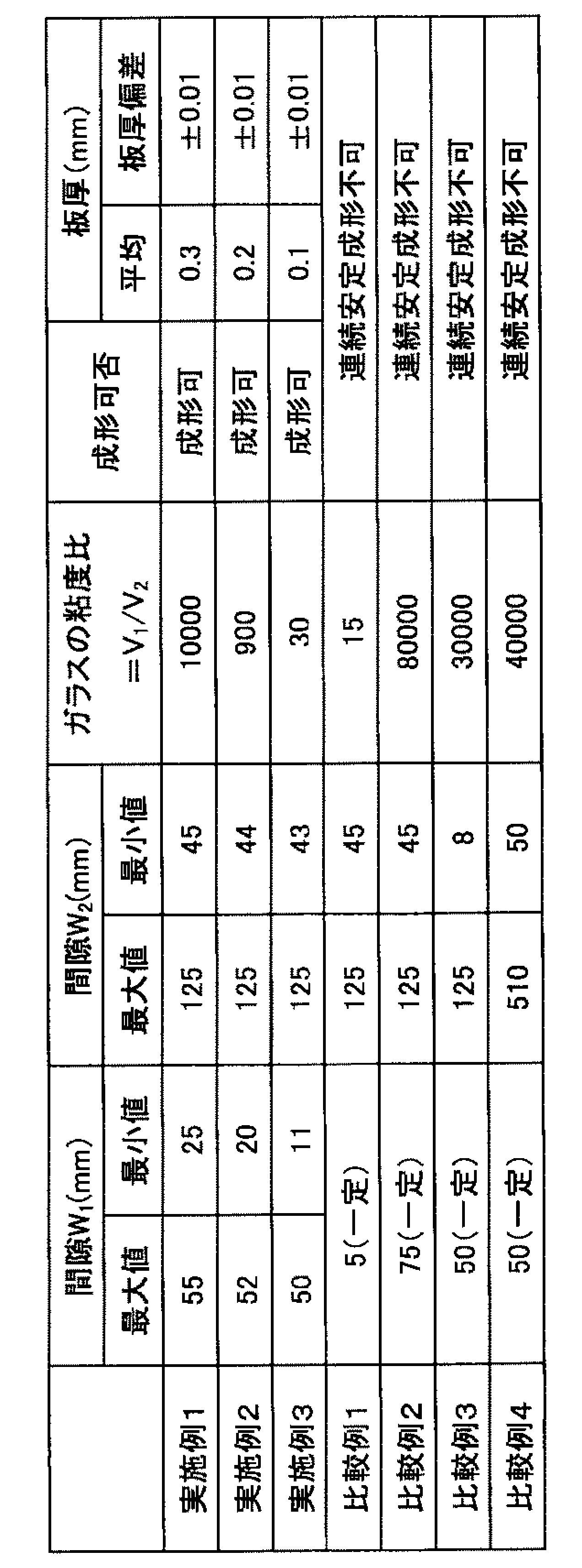
- Example 1 In Example 1, an alkali-free glass plate having a thickness of 0.3 mm was produced using the glass plate production apparatus shown in FIGS. 1 and 3. As the first opening member 4, a 25 mm thick ceramic fiber heat insulating plate (manufactured by NICHIAS, T / # 5461 RF board 16MD) was used. This heat insulating plate had a thermal conductivity of 0.2 W / m ⁇ K at the use temperature and a heat transfer resistance at the use temperature of 0.13 m 2 K / W.
- Gap W 1 is, the minimum value is set to 25mm, and the maximum value and 55mm.
- Gap W 2 is, the minimum value is set to 45mm, and the maximum value and 125mm.
- the widthwise center of the temperature of the molten glass 5 in the zirconia of the upper edge 1a of the molded body 1 was measured and converted to a viscosity V 1. Further, the widthwise center of the temperature of the glass ribbon 5A in the forming chamber opening 3 was measured and converted to a viscosity V 2.
- the viscosity ratio V 2 / V 1 was 10,000.
- the thickness of the central portion in the width direction of the molded glass ribbon 5A was measured.
- Example 2 The results are shown in Table 1. The average thickness was 0.3 mm, and a high-quality thin alkali-free glass plate with a maximum thickness deviation of ⁇ 0.01 mm was obtained.
- Example 2 an alkali-free glass plate having a thickness of 0.2 mm was produced using the glass plate production apparatus shown in FIGS. 1 and 3.
- the first opening member 4 a 25 mm thick ceramic fiber heat insulating plate (manufactured by NICHIAS, T / # 5461 RF board 16MD) was used. This heat insulating plate had a thermal conductivity of 0.2 W / m ⁇ K at the use temperature and a heat transfer resistance at the use temperature of 0.13 m 2 K / W.
- Gap W 1 is, the minimum value is set to 20mm, and the maximum value and 52mm.
- Gap W 2 is, the minimum value is set to 44mm, and the maximum value and 125mm.
- the widthwise center of the temperature of the molten glass 5 in the zirconia of the upper edge 1a of the molded body 1 was measured and converted to a viscosity V 1. Further, the widthwise center of the temperature of the glass ribbon 5A in the forming chamber opening 3 was measured and converted to a viscosity V 2.
- the viscosity ratio V 2 / V 1 was 900.
- the thickness of the central portion in the width direction of the molded glass ribbon 5A was measured.
- Example 3 An alkali-free glass plate having a thickness of 0.1 mm was manufactured using the glass plate manufacturing apparatus shown in FIGS. 1 and 3.
- a 25 mm thick ceramic fiber heat insulating plate manufactured by NICHIAS, T / # 5461 RF board 16MD was used. This heat insulating plate had a thermal conductivity of 0.2 W / m ⁇ K at the use temperature and a heat transfer resistance at the use temperature of 0.13 m 2 K / W.
- Gap W 1 is, the minimum value is set to 11mm, and the maximum value and 50mm.
- Gap W 2 is, the minimum value is set to 43mm, and the maximum value and 125mm.
- the widthwise center of the temperature of the molten glass 5 in the zirconia of the upper edge 1a of the molded body 1 was measured and converted to a viscosity V 1. Further, the widthwise center of the temperature of the glass ribbon 5A in the forming chamber opening 3 was measured and converted to a viscosity V 2. The viscosity ratio V 2 / V 1 was 30.
- the thickness of the central portion in the width direction of the molded glass ribbon 5A was measured.
- Example 1 The results are shown in Table 1. The average thickness was 0.1 mm, and a high-quality thin alkali-free glass plate having a maximum thickness deviation of ⁇ 0.01 mm was obtained.
- Comparative Example 1 In Comparative Example 1, in place of the first aperture member 4 shown in FIG. 3, except using the first aperture member 4B shown in FIG. 6, changing the setting of the gap W 1 (see Table 1), Example The experiment was conducted in the same manner as in 1. The viscosity ratio V 2 / V 1 was 15.
- Comparative Example 2 Since the gap W 1 is too small, heat transfer between the molding chamber 2 and the lower forming chamber 2 is suppressed. As a result, the viscosity of the glass ribbon 5A was lowered, the width of the glass ribbon 5A was narrowed, the glass ribbon 5A was cut in the middle, and stable continuous molding could not be performed.
- Comparative Example 2 In Comparative Example 2, instead of the first aperture member 4 shown in FIG. 3, except using the first aperture member 4B shown in FIG. 6, changing the setting of the gap W 1 (see Table 1), Example The experiment was conducted in the same manner as in 1. The viscosity ratio V 2 / V 1 was 80,000.
- Comparative Example 3 In Comparative Example 3, in place of the first aperture member 4 shown in FIG. 3, except using the first aperture member 4B shown in FIG. 6, changing the setting of the gap W 1 and the gap W 2 (see Table 1) Were conducted in the same manner as in Example 1.
- the viscosity ratio V 2 / V 1 was 30000.
- Comparative Example 4 Since the minimum value of the gap W 2 was too small, heat transfer between the molding chamber 2 and the lower portion of the molding chamber 2 was suppressed. As a result, the temperature of the end portion in the width direction of the glass ribbon 5A increases, the temperature difference between the center and the end portion in the width direction of the glass ribbon 5A increases, and the glass ribbon 5A can be evenly stretched in the width direction. Therefore, stable continuous molding could not be performed.
- Comparative Example 4 In Comparative Example 4, instead of the first aperture member 4 shown in FIG. 3, except using the first aperture member 4B shown in FIG. 6, changing the setting of the gap W 1 and the gap W 2 (see Table 1) Were conducted in the same manner as in Example 1. The viscosity ratio V 2 / V 1 was 40000.
- the present invention it is possible to provide a glass plate manufacturing method and a manufacturing apparatus capable of easily manufacturing a high-quality glass plate.
Landscapes
- Chemical & Material Sciences (AREA)
- Engineering & Computer Science (AREA)
- Materials Engineering (AREA)
- Organic Chemistry (AREA)
- Mechanical Engineering (AREA)
- Re-Forming, After-Treatment, Cutting And Transporting Of Glass Products (AREA)
- Glass Compositions (AREA)
- Joining Of Glass To Other Materials (AREA)
Abstract
Description
成形室内の成形体の両側面に沿って溶融ガラスを流下させること、前記成形体の下縁部直下で合流させて一体化させること、および当該一体化した板状のガラスリボンを成形室開口から下方に引き出すことを含むガラス板の製造方法において、
前記成形体の上縁における溶融ガラスの幅方向中央の粘度(V1)と前記成形室開口を通過するガラスリボンの幅方向中央の粘度(V2)との粘度比(V2/V1)を20以上50000以下に設定し、
前記成形室開口を通過するガラスリボンの幅方向中央の厚さを1.0mm以下に設定し、
前記成形室開口と前記成形体の下縁を含む鉛直面との間の該鉛直面と直交する方向における間隙を8mm以上70mm以下に設定し、
前記成形室開口の前記ガラスリボンの幅方向側の側面部分と、前記成形室開口を通過するガラスリボンの幅方向のそれぞれの端部との間の間隙を10mm以上500mm以下に設定する。
下縁部直下で両側面に沿って流下させた溶融ガラスを合流させて一体化させる成形体と、
内部に前記成形体が配置される成形室と、
前記成形体により一体化した板状のガラスリボンを前記成形室から下方に引き出すための成形室開口とを有するガラス板の製造装置において、
前記成形体の上縁における溶融ガラスの幅方向中央の粘度(V1)と前記成形室開口を通過するガラスリボンの幅方向中央の粘度(V2)との粘度比(V2/V1)を20以上50000以下に設定し、
前記成形室開口を通過するガラスリボンの幅方向中央の厚さを1.0mm以下に設定し、
前記成形室開口と前記成形体の下縁を含む鉛直面との間の該鉛直面と直交する方向における間隙を8mm以上70mm以下に設定し、
前記成形室開口の前記ガラスリボンの幅方向側の側面部分と、前記成形室開口を通過するガラスリボンの幅方向のそれぞれの端部との間の間隙を10mm以上500mm以下に設定する。
成形室2には、溶融ガラス5やガラスリボン5Aの上下方向及び幅方向の温度分布を制御するため、第2の発熱体12、第3の発熱体13、冷却体14が設置されている。
(実施例1)
実施例1では、図1及び図3に示すガラス板の製造装置を用いて、厚さ0.3mmの無アルカリガラス板を製造した。第1の開口部材4としては、厚さ25mmのセラミックスファイバー製の断熱板(ニチアス社製、T/#5461 RFボード 16MD)を用いた。この断熱板は、使用温度における熱伝導率が0.2W/m・Kであり、使用温度における熱伝達抵抗が0.13m2K/Wであった。
(実施例2)
実施例2では、図1及び図3に示すガラス板の製造装置を用いて、厚さ0.2mmの無アルカリガラス板を製造した。第1の開口部材4としては、厚さ25mmのセラミックスファイバー製の断熱板(ニチアス社製、T/#5461 RFボード 16MD)を用いた。この断熱板は、使用温度における熱伝導率が0.2W/m・Kであり、使用温度における熱伝達抵抗が0.13m2K/Wであった。
(実施例3)
実施例3では、図1及び図3に示すガラス板の製造装置を用いて、厚さ0.1mmの無アルカリガラス板を製造した。第1の開口部材4としては、厚さ25mmのセラミックスファイバー製の断熱板(ニチアス社製、T/#5461 RFボード 16MD)を用いた。この断熱板は、使用温度における熱伝導率が0.2W/m・Kであり、使用温度における熱伝達抵抗が0.13m2K/Wであった。
(比較例1)
比較例1では、図3に示す第1の開口部材4の代わりに、図6に示す第1の開口部材4Bを用い、間隙W1の設定を変更した(表1参照)以外は、実施例1と同様にして、実験を行った。粘度比V2/V1は、15であった。
(比較例2)
比較例2では、図3に示す第1の開口部材4の代わりに、図6に示す第1の開口部材4Bを用い、間隙W1の設定を変更した(表1参照)以外は、実施例1と同様にして、実験を行った。粘度比V2/V1は、80000であった。
(比較例3)
比較例3では、図3に示す第1の開口部材4の代わりに、図6に示す第1の開口部材4Bを用い、間隙W1及び間隙W2の設定を変更した(表1参照)以外は、実施例1と同様にして、実験を行った。粘度比V2/V1は、30000であった。
(比較例4)
比較例4では、図3に示す第1の開口部材4の代わりに、図6に示す第1の開口部材4Bを用い、間隙W1及び間隙W2の設定を変更した(表1参照)以外は、実施例1と同様にして、実験を行った。粘度比V2/V1は、40000であった。
本出願は、2009年7月13日出願の日本特許出願2009-164345に基づくものであり、その内容はここに参照として取り込まれる。
1a 上縁
1b 下縁部
1c 下縁
2 成形室
3 成形室開口
4 第1の開口部材
5 溶融ガラス
5A ガラスリボン
18 鉛直面
20 隔壁部材
21~27 成形室用ブロック
30 隔壁部材
31~37 成形室用ブロック
41 連通室
42 連通室開口
43 第2の開口部材
50 隔壁部材
51~57 連通室用ブロック
60 隔壁部材
61~67 連通室用ブロック
Claims (9)
- 成形室内の成形体の両側面に沿って溶融ガラスを流下させること、
前記成形体の下縁部直下で合流させて一体化させること、および
当該一体化した板状のガラスリボンを成形室開口から下方に引き出すこと、
を含むガラス板の製造方法において、
前記成形体の上縁における溶融ガラスの幅方向中央の粘度(V1)と前記成形室開口を通過するガラスリボンの幅方向中央の粘度(V2)との粘度比(V2/V1)を20以上50000以下に設定し、
前記成形室開口を通過するガラスリボンの幅方向中央の厚さを1.0mm以下に設定し、
前記成形室開口と前記成形体の下縁を含む鉛直面との間の、該鉛直面と直交する方向における間隙を8mm以上70mm以下に設定し、
前記成形室開口の前記ガラスリボンの幅方向側の側面部分と、前記成形室開口を通過するガラスリボンの幅方向のそれぞれの端部との間の間隙を10mm以上500mm以下に設定するガラス板の製造方法。 - 前記成形室開口が第1の開口部材から形成され、前記第1の開口部材が、前記成形室開口を通過するガラスリボンの幅方向に分割された複数の成形室用ブロックを含み、
一若しくは複数の前記成形室用ブロックを前記鉛直面に対して接近、離間する方向に移動させること、又は、交換することにより、前記成形室開口の形状寸法を調節又は変更する請求項1記載のガラス板の製造方法。 - 前記成形室開口の側面の少なくとも一部と前記鉛直面との間の、前記鉛直面と直交する方向における間隙が、前記ガラスリボンの幅方向に変化するように、前記成形室開口の形状寸法を調節又は変更する請求項2記載のガラス板の製造方法。
- 前記成形室開口の形状寸法を、製造されたガラス板の形状寸法、前記成形室内の温度分布、又は前記成形室開口内の温度分布に基づいて調節又は変更する請求項2又は3記載のガラス板の製造方法。
- 前記成形体の両側面に沿って前記溶融ガラスを流下させていないとき、前記複数の成形室用ブロックによって前記成形室開口が実質的に閉塞される請求項2~4いずれか一項記載のガラス板の製造方法。
- 前記成形室は、前記成形室開口を介して連通室と連通されており、
前記連通室から前記ガラスリボンを下方に引き出すための連通室開口を形成する第2の開口部材は、前記連通室開口を通過するガラスリボンの幅方向に分割された複数の連通室用ブロックを含み、
一若しくは複数の前記連通室用ブロックを前記鉛直面に対して接近、離間する方向に移動させること、又は、交換することにより、前記連通室開口の形状寸法を調節又は変更する請求項1~5いずれか一項記載のガラス板の製造方法。 - 下縁部直下で両側面に沿って流下させた溶融ガラスを合流させて一体化させる成形体と、
内部に前記成形体が配置される成形室と、
前記成形体により一体化した板状のガラスリボンを前記成形室から下方に引き出すための成形室開口とを有するガラス板の製造装置において、
前記成形体の上縁における溶融ガラスの幅方向中央の粘度(V1)と前記成形室開口を通過するガラスリボンの幅方向中央の粘度(V2)との粘度比(V2/V1)を20以上50000以下に設定し、
前記成形室開口を通過するガラスリボンの幅方向中央の厚さを1.0mm以下に設定し、
前記成形室開口と前記成形体の下縁を含む鉛直面との間の、該鉛直面と直交する方向における間隙を8mm以上70mm以下に設定し、
前記成形室開口の前記ガラスリボンの幅方向側の側面部分と、前記成形室開口を通過するガラスリボンの幅方向のそれぞれの端部との間の間隙を10mm以上500mm以下に設定するガラス板の製造装置。 - 前記成形室開口が第1の開口部材から形成され、前記第1の開口部材が、前記成形室開口を通過するガラスリボンの幅方向に分割された複数の成形室用ブロックを含み、
一若しくは複数の前記成形室用ブロックが前記鉛直面に対して接近、離間する方向に移動可能、又は、交換可能であることにより、前記成形室開口の形状寸法を調節又は変更可能である請求項7記載のガラス板の製造装置。 - 前記成形室に前記成形室開口を介して連通する連通室と、
前記連通室から前記ガラスリボンを下方に引き出すための連通室開口とを更に有し、
前記連通室開口を形成する第2の開口部材は、前記ガラスリボンの幅方向に分割された複数の連通室用ブロックを含み、
一若しくは複数の前記連通室用ブロックが前記鉛直面に対して接近、離間する方向に移動可能、又は、交換可能であることにより、前記連通室開口の形状寸法を調節又は変更可能である請求項7又は8記載のガラス板の製造装置。
Priority Applications (5)
| Application Number | Priority Date | Filing Date | Title |
|---|---|---|---|
| JP2011522757A JP5648635B2 (ja) | 2009-07-13 | 2010-05-21 | ガラス板の製造方法及び製造装置 |
| KR1020127000981A KR101751082B1 (ko) | 2009-07-13 | 2010-05-21 | 유리판의 제조 방법 및 제조 장치 |
| EP10799679.5A EP2455346B1 (en) | 2009-07-13 | 2010-05-21 | Glass plate manufacturing method |
| CN201080031639.6A CN102471121B (zh) | 2009-07-13 | 2010-05-21 | 玻璃板的制造方法及制造装置 |
| US13/349,798 US8453478B2 (en) | 2009-07-13 | 2012-01-13 | Glass plate manufacturing method and manufacturing device |
Applications Claiming Priority (2)
| Application Number | Priority Date | Filing Date | Title |
|---|---|---|---|
| JP2009-164345 | 2009-07-13 | ||
| JP2009164345 | 2009-07-13 |
Related Child Applications (1)
| Application Number | Title | Priority Date | Filing Date |
|---|---|---|---|
| US13/349,798 Continuation US8453478B2 (en) | 2009-07-13 | 2012-01-13 | Glass plate manufacturing method and manufacturing device |
Publications (1)
| Publication Number | Publication Date |
|---|---|
| WO2011007617A1 true WO2011007617A1 (ja) | 2011-01-20 |
Family
ID=43449227
Family Applications (1)
| Application Number | Title | Priority Date | Filing Date |
|---|---|---|---|
| PCT/JP2010/058670 Ceased WO2011007617A1 (ja) | 2009-07-13 | 2010-05-21 | ガラス板の製造方法及び製造装置 |
Country Status (7)
| Country | Link |
|---|---|
| US (1) | US8453478B2 (ja) |
| EP (1) | EP2455346B1 (ja) |
| JP (1) | JP5648635B2 (ja) |
| KR (1) | KR101751082B1 (ja) |
| CN (1) | CN102471121B (ja) |
| TW (1) | TWI481571B (ja) |
| WO (1) | WO2011007617A1 (ja) |
Cited By (13)
| Publication number | Priority date | Publication date | Assignee | Title |
|---|---|---|---|---|
| WO2012166446A1 (en) | 2011-05-27 | 2012-12-06 | Corning Incorporated | Non-polished glass wafer, thinning system and method for using the non-polished glass wafer to thin a semiconductor wafer |
| US20130133370A1 (en) * | 2011-11-28 | 2013-05-30 | Olus Naili Boratav | Apparatus for reducing radiative heat loss from a forming body in a glass forming process |
| US8826694B2 (en) * | 2010-09-30 | 2014-09-09 | Avanstrate Inc. | Method of manufacturing glass sheet |
| US20150225276A1 (en) * | 2011-03-31 | 2015-08-13 | Avanstrate Inc. | Glass-substrate manufacturing method |
| WO2015125943A1 (ja) * | 2014-02-21 | 2015-08-27 | AvanStrate株式会社 | ガラス板の製造方法、及び、ガラス板の製造装置 |
| JP2016069273A (ja) * | 2014-09-30 | 2016-05-09 | AvanStrate株式会社 | ディスプレイ用ガラス基板の製造方法 |
| WO2017002626A1 (ja) * | 2015-06-30 | 2017-01-05 | AvanStrate株式会社 | ガラス基板の製造方法及びガラス基板製造装置 |
| JP2017065983A (ja) * | 2015-09-30 | 2017-04-06 | AvanStrate株式会社 | ガラス板の製造方法およびガラス板の製造装置 |
| WO2018098125A1 (en) * | 2016-11-23 | 2018-05-31 | Corning Incorporated | Method and apparatus for glass ribbon thermal control |
| JP2019026489A (ja) * | 2017-07-26 | 2019-02-21 | 日本電気硝子株式会社 | ガラス物品の製造方法及び製造装置 |
| JP2019536727A (ja) * | 2016-11-23 | 2019-12-19 | コーニング インコーポレイテッド | 成形本体の寸法変動を補償するための方法および装置 |
| JP2021500298A (ja) * | 2017-10-20 | 2021-01-07 | コーニング インコーポレイテッド | 中実でモノリシックな前端部を含む熱遮蔽部を有する装置 |
| WO2022014288A1 (ja) * | 2020-07-16 | 2022-01-20 | 日本電気硝子株式会社 | ガラス物品の製造方法 |
Families Citing this family (13)
| Publication number | Priority date | Publication date | Assignee | Title |
|---|---|---|---|---|
| JP5023241B2 (ja) * | 2010-09-30 | 2012-09-12 | AvanStrate株式会社 | ガラス板の製造方法 |
| US8869562B2 (en) | 2012-11-29 | 2014-10-28 | Corning Incorporated | Glass forming apparatus |
| US9290403B2 (en) | 2013-02-25 | 2016-03-22 | Corning Incorporated | Repositionable heater assemblies for glass production lines and methods of managing temperature of glass in production lines |
| US9682882B2 (en) | 2014-07-17 | 2017-06-20 | Corning Incorporated | Methods for producing a glass ribbon |
| CN204779315U (zh) * | 2014-11-24 | 2015-11-18 | 康宁股份有限公司 | 用于制造玻璃带的设备 |
| CN107108308B (zh) * | 2014-12-19 | 2020-04-28 | 康宁股份有限公司 | 制造玻璃带的装置 |
| JP6823457B2 (ja) * | 2015-06-30 | 2021-02-03 | AvanStrate株式会社 | ディスプレイ用ガラス基板の製造方法 |
| CN109219581A (zh) * | 2016-05-24 | 2019-01-15 | 康宁股份有限公司 | 玻璃制造设备及方法 |
| CN108996890A (zh) * | 2017-06-07 | 2018-12-14 | 秦皇岛玻璃工业研究设计院有限公司 | 利用玻璃纤维熔窑排放料制备超薄玻璃的设备和方法 |
| JP2020528394A (ja) * | 2017-07-21 | 2020-09-24 | コーニング インコーポレイテッド | ガラスリボンでの調整可能な伝熱のための方法および装置 |
| KR102724254B1 (ko) * | 2018-10-26 | 2024-10-31 | 니폰 덴키 가라스 가부시키가이샤 | 유리 물품의 제조 방법 |
| WO2022051077A1 (en) * | 2020-09-02 | 2022-03-10 | Corning Incorporated | Apparatus and method to improve attributes of drawn glass |
| NL2027190B1 (en) * | 2020-11-13 | 2022-06-30 | Corning Inc | Apparatus for, and method of, roll forming sheets of high refractive index glass |
Citations (6)
| Publication number | Priority date | Publication date | Assignee | Title |
|---|---|---|---|---|
| JPH02149437A (ja) | 1988-11-30 | 1990-06-08 | Hoya Corp | ガラス板の製造装置 |
| JPH0546929U (ja) | 1991-11-27 | 1993-06-22 | ホーヤ株式会社 | ガラス板の製造装置 |
| JP2007051028A (ja) * | 2005-08-18 | 2007-03-01 | Nippon Electric Glass Co Ltd | 板ガラスの成形方法 |
| JP2008088005A (ja) * | 2006-09-29 | 2008-04-17 | Hoya Corp | 板ガラスの製造装置及び製造方法、並びにガラス製品及び液晶ディスプレイの製造方法 |
| JP2009519884A (ja) * | 2005-12-15 | 2009-05-21 | ブルース テクノロジー エルエルシー | オーバーフローダウンドローガラス成形方法および装置 |
| JP2009149463A (ja) * | 2007-12-20 | 2009-07-09 | Nippon Electric Glass Co Ltd | ガラス板の製造方法及び製造設備 |
Family Cites Families (3)
| Publication number | Priority date | Publication date | Assignee | Title |
|---|---|---|---|---|
| US2691247A (en) * | 1948-12-17 | 1954-10-12 | Union Des Verreries Mecaniques | Process of and apparatus for drawing glass into sheet form |
| US8042361B2 (en) * | 2004-07-20 | 2011-10-25 | Corning Incorporated | Overflow downdraw glass forming method and apparatus |
| WO2009081740A1 (ja) * | 2007-12-25 | 2009-07-02 | Nippon Electric Glass Co., Ltd. | ガラス板の製造方法及び製造設備 |
-
2010
- 2010-05-21 EP EP10799679.5A patent/EP2455346B1/en not_active Not-in-force
- 2010-05-21 WO PCT/JP2010/058670 patent/WO2011007617A1/ja not_active Ceased
- 2010-05-21 KR KR1020127000981A patent/KR101751082B1/ko not_active Expired - Fee Related
- 2010-05-21 JP JP2011522757A patent/JP5648635B2/ja not_active Expired - Fee Related
- 2010-05-21 CN CN201080031639.6A patent/CN102471121B/zh not_active Expired - Fee Related
- 2010-07-07 TW TW099122364A patent/TWI481571B/zh not_active IP Right Cessation
-
2012
- 2012-01-13 US US13/349,798 patent/US8453478B2/en not_active Expired - Fee Related
Patent Citations (6)
| Publication number | Priority date | Publication date | Assignee | Title |
|---|---|---|---|---|
| JPH02149437A (ja) | 1988-11-30 | 1990-06-08 | Hoya Corp | ガラス板の製造装置 |
| JPH0546929U (ja) | 1991-11-27 | 1993-06-22 | ホーヤ株式会社 | ガラス板の製造装置 |
| JP2007051028A (ja) * | 2005-08-18 | 2007-03-01 | Nippon Electric Glass Co Ltd | 板ガラスの成形方法 |
| JP2009519884A (ja) * | 2005-12-15 | 2009-05-21 | ブルース テクノロジー エルエルシー | オーバーフローダウンドローガラス成形方法および装置 |
| JP2008088005A (ja) * | 2006-09-29 | 2008-04-17 | Hoya Corp | 板ガラスの製造装置及び製造方法、並びにガラス製品及び液晶ディスプレイの製造方法 |
| JP2009149463A (ja) * | 2007-12-20 | 2009-07-09 | Nippon Electric Glass Co Ltd | ガラス板の製造方法及び製造設備 |
Non-Patent Citations (1)
| Title |
|---|
| See also references of EP2455346A4 |
Cited By (30)
| Publication number | Priority date | Publication date | Assignee | Title |
|---|---|---|---|---|
| US8826694B2 (en) * | 2010-09-30 | 2014-09-09 | Avanstrate Inc. | Method of manufacturing glass sheet |
| US9533908B2 (en) * | 2011-03-31 | 2017-01-03 | Avanstrate Inc. | Glass-substrate manufacturing method |
| US20150225276A1 (en) * | 2011-03-31 | 2015-08-13 | Avanstrate Inc. | Glass-substrate manufacturing method |
| EP2715780A4 (en) * | 2011-05-27 | 2014-11-19 | Corning Inc | NON-POLISHED GLASS WAFERS, DILUTION SYSTEM AND METHOD OF USE OF THE WATER OF NON-POLISHED GLASS FOR DILUTING A SEMICONDUCTOR WAFER |
| US9573835B2 (en) | 2011-05-27 | 2017-02-21 | Corning Incorporated | Non-polished glass wafer, thinning system and method for using the non-polished glass wafer to thin a semiconductor wafer |
| WO2012166446A1 (en) | 2011-05-27 | 2012-12-06 | Corning Incorporated | Non-polished glass wafer, thinning system and method for using the non-polished glass wafer to thin a semiconductor wafer |
| US9227295B2 (en) | 2011-05-27 | 2016-01-05 | Corning Incorporated | Non-polished glass wafer, thinning system and method for using the non-polished glass wafer to thin a semiconductor wafer |
| US20160096767A1 (en) * | 2011-05-27 | 2016-04-07 | Corning Incorporated | Non-polished glass wafer, thinning system and method for using the non-polished glass wafer to thin a semiconductor wafer |
| US20130133370A1 (en) * | 2011-11-28 | 2013-05-30 | Olus Naili Boratav | Apparatus for reducing radiative heat loss from a forming body in a glass forming process |
| CN104203846A (zh) * | 2011-11-28 | 2014-12-10 | 康宁股份有限公司 | 用于在玻璃成型过程中减小来自成型体的辐射热损失的设备 |
| CN105121365A (zh) * | 2014-02-21 | 2015-12-02 | 安瀚视特控股株式会社 | 玻璃板的制造方法及玻璃板的制造装置 |
| WO2015125943A1 (ja) * | 2014-02-21 | 2015-08-27 | AvanStrate株式会社 | ガラス板の製造方法、及び、ガラス板の製造装置 |
| CN105121365B (zh) * | 2014-02-21 | 2017-09-19 | 安瀚视特控股株式会社 | 玻璃板的制造方法及玻璃板的制造装置 |
| JP5944578B2 (ja) * | 2014-02-21 | 2016-07-05 | AvanStrate株式会社 | ガラス板の製造方法、及び、ガラス板の製造装置 |
| JP2016069273A (ja) * | 2014-09-30 | 2016-05-09 | AvanStrate株式会社 | ディスプレイ用ガラス基板の製造方法 |
| WO2017002626A1 (ja) * | 2015-06-30 | 2017-01-05 | AvanStrate株式会社 | ガラス基板の製造方法及びガラス基板製造装置 |
| JPWO2017002626A1 (ja) * | 2015-06-30 | 2018-04-12 | AvanStrate株式会社 | ガラス基板の製造方法及びガラス基板製造装置 |
| JP2017065983A (ja) * | 2015-09-30 | 2017-04-06 | AvanStrate株式会社 | ガラス板の製造方法およびガラス板の製造装置 |
| JP7085546B2 (ja) | 2016-11-23 | 2022-06-16 | コーニング インコーポレイテッド | 成形本体の寸法変動を補償するための方法および装置 |
| WO2018098125A1 (en) * | 2016-11-23 | 2018-05-31 | Corning Incorporated | Method and apparatus for glass ribbon thermal control |
| JP2019536727A (ja) * | 2016-11-23 | 2019-12-19 | コーニング インコーポレイテッド | 成形本体の寸法変動を補償するための方法および装置 |
| US11512015B2 (en) | 2016-11-23 | 2022-11-29 | Corning Incorporated | Method and apparatus for glass ribbon thermal control |
| JP2019026489A (ja) * | 2017-07-26 | 2019-02-21 | 日本電気硝子株式会社 | ガラス物品の製造方法及び製造装置 |
| JP2021500298A (ja) * | 2017-10-20 | 2021-01-07 | コーニング インコーポレイテッド | 中実でモノリシックな前端部を含む熱遮蔽部を有する装置 |
| JP7429638B2 (ja) | 2017-10-20 | 2024-02-08 | コーニング インコーポレイテッド | 中実でモノリシックな前端部を含む熱遮蔽部を有する装置 |
| JP2022018816A (ja) * | 2020-07-16 | 2022-01-27 | 日本電気硝子株式会社 | ガラス物品の製造方法 |
| WO2022014288A1 (ja) * | 2020-07-16 | 2022-01-20 | 日本電気硝子株式会社 | ガラス物品の製造方法 |
| KR20230041714A (ko) * | 2020-07-16 | 2023-03-24 | 니폰 덴키 가라스 가부시키가이샤 | 유리 물품의 제조 방법 |
| JP7495662B2 (ja) | 2020-07-16 | 2024-06-05 | 日本電気硝子株式会社 | ガラス物品の製造方法 |
| KR102822675B1 (ko) | 2020-07-16 | 2025-06-20 | 니폰 덴키 가라스 가부시키가이샤 | 유리 물품의 제조 방법 |
Also Published As
| Publication number | Publication date |
|---|---|
| TW201107254A (en) | 2011-03-01 |
| KR101751082B1 (ko) | 2017-06-26 |
| US8453478B2 (en) | 2013-06-04 |
| JP5648635B2 (ja) | 2015-01-07 |
| US20120159990A1 (en) | 2012-06-28 |
| EP2455346A4 (en) | 2013-11-06 |
| JPWO2011007617A1 (ja) | 2012-12-27 |
| EP2455346A1 (en) | 2012-05-23 |
| CN102471121B (zh) | 2015-03-04 |
| KR20120038966A (ko) | 2012-04-24 |
| EP2455346B1 (en) | 2016-01-13 |
| TWI481571B (zh) | 2015-04-21 |
| CN102471121A (zh) | 2012-05-23 |
Similar Documents
| Publication | Publication Date | Title |
|---|---|---|
| JP5648635B2 (ja) | ガラス板の製造方法及び製造装置 | |
| KR101644671B1 (ko) | 유리판의 제조 방법 | |
| JP4383050B2 (ja) | 薄ガラス板製造方法及び装置 | |
| CN203173971U (zh) | 玻璃板制造装置 | |
| KR101644670B1 (ko) | 유리판의 제조 방법 | |
| KR20140107277A (ko) | 유리 형성 공정에서 성형체로부터 방사 열 손실을 감소시키기 위한 장치 | |
| KR102459796B1 (ko) | 유리판의 제조 방법, 및 유리판의 제조 장치 | |
| JPH0546929U (ja) | ガラス板の製造装置 |
Legal Events
| Date | Code | Title | Description |
|---|---|---|---|
| WWE | Wipo information: entry into national phase |
Ref document number: 201080031639.6 Country of ref document: CN |
|
| 121 | Ep: the epo has been informed by wipo that ep was designated in this application |
Ref document number: 10799679 Country of ref document: EP Kind code of ref document: A1 |
|
| ENP | Entry into the national phase |
Ref document number: 2011522757 Country of ref document: JP Kind code of ref document: A |
|
| WWE | Wipo information: entry into national phase |
Ref document number: 2010799679 Country of ref document: EP |
|
| ENP | Entry into the national phase |
Ref document number: 20127000981 Country of ref document: KR Kind code of ref document: A |
|
| NENP | Non-entry into the national phase |
Ref country code: DE |