WO2011007996A2 - Caméra vidéo - Google Patents
Caméra vidéo Download PDFInfo
- Publication number
- WO2011007996A2 WO2011007996A2 PCT/KR2010/004529 KR2010004529W WO2011007996A2 WO 2011007996 A2 WO2011007996 A2 WO 2011007996A2 KR 2010004529 W KR2010004529 W KR 2010004529W WO 2011007996 A2 WO2011007996 A2 WO 2011007996A2
- Authority
- WO
- WIPO (PCT)
- Prior art keywords
- control
- emitting diode
- light emitting
- value
- brightness
- Prior art date
- Legal status (The legal status is an assumption and is not a legal conclusion. Google has not performed a legal analysis and makes no representation as to the accuracy of the status listed.)
- Ceased
Links
Images




Classifications
-
- H—ELECTRICITY
- H04—ELECTRIC COMMUNICATION TECHNIQUE
- H04N—PICTORIAL COMMUNICATION, e.g. TELEVISION
- H04N23/00—Cameras or camera modules comprising electronic image sensors; Control thereof
- H04N23/70—Circuitry for compensating brightness variation in the scene
- H04N23/71—Circuitry for evaluating the brightness variation
-
- H—ELECTRICITY
- H04—ELECTRIC COMMUNICATION TECHNIQUE
- H04N—PICTORIAL COMMUNICATION, e.g. TELEVISION
- H04N23/00—Cameras or camera modules comprising electronic image sensors; Control thereof
- H04N23/70—Circuitry for compensating brightness variation in the scene
- H04N23/73—Circuitry for compensating brightness variation in the scene by influencing the exposure time
-
- H—ELECTRICITY
- H04—ELECTRIC COMMUNICATION TECHNIQUE
- H04N—PICTORIAL COMMUNICATION, e.g. TELEVISION
- H04N23/00—Cameras or camera modules comprising electronic image sensors; Control thereof
- H04N23/70—Circuitry for compensating brightness variation in the scene
- H04N23/74—Circuitry for compensating brightness variation in the scene by influencing the scene brightness using illuminating means
Definitions
- the present invention relates to a moving image camera, and more particularly, to prevent saturation of a bright part of an image due to lighting (entering a control mode) of a lighting device, and to maintain maximum exposure time of an aperture and an electronic shutter even when the lighting device is turned on.
- the present invention relates to a moving image camera capable of obtaining a high quality image of a dark portion of an image.
- AE auto exposure
- IRIS Adjust the exposure of light with the aperture
- HSS / LSS Adjust the exposure time with the shutter
- AGC Automatic gain Control
- IR-LED Infrared Light Emitting Diode
- the IR-LED is an infrared region that is invisible to the person, but the party photographed by the camera cannot see the light, but the resultant image output through the camera is bright.
- CDS sensor is used together.
- the CDS sensor is a photoconductive effect sensor that automatically turns the lighting device on and off by changing the resistance value according to the amount of light.
- an additional circuit may be configured at the CDS sensor stage to variably change the brightness of the IR-LED.
- FIG. 1 a block diagram of a lighting apparatus generally used in a security camera is illustrated in FIG. 1.
- the iris adjusts the amount of light by varying the size of a hole through which light enters.
- the electronic shutter controls the amount of light by varying the time that light accumulates in the image pickup device.
- the gain amplifier also amplifies the amount of light electrically converted by the imaging device.
- the amount of charge for the amount of light thus amplified is fed back by changing the automatic exposure control value (aperture control value, electronic shutter control value, gain amplification control value) by the deviation compared with the charge amount preset in the automatic exposure controller.
- the lighting apparatus generally operates independently of the automatic exposure controller.
- the output voltage of the CDS sensor varies according to the amount of light coming from the outside.
- this variable When this variable reaches a certain threshold, it is used as an on / off switch of the lighting device by operating the lighting device.
- a PWM signal generator is provided between the CDS sensor and the lighting device to generate a PWM control signal according to a variable value, thereby changing the lighting device.
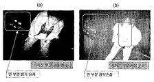
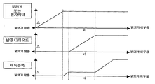
- the control state of each element is as shown in FIG. 2, and the image obtained according to the above is as shown in FIG. That is, since the lighting point of the light emitting diode is not known to the controller, the iris or shutter closes at the ON point of the light emitting diode, so that the close portion is saturated, and the far portion lacks light, resulting in the inability to obtain image information.
- the main point here is that this problem occurs because the lighting unit and the automatic exposure control section are separated.
- the automatic exposure controller is included in the DSP that handles most of the camera functions.
- the digital signal processor DSP performs functions such as average brightness calculation of an image for AE control, automatic color / monochrome switching according to image brightness, and the like, in addition to AE control.
- the inability to know the exact timing of the lighting operation in these DSPs is not knowing when to apply the algorithm to avoid saturation of nearby objects and when to automatically switch colors and monochrome.
- the DSP knows the exact time of operation of the lighting device, avoiding saturation of near objects, and at the same time, taking the maximum amount of light from distant parts to obtain a clear image, and automatic color /
- the DSP knows the exact time of operation of the lighting device, avoiding saturation of near objects, and at the same time, taking the maximum amount of light from distant parts to obtain a clear image, and automatic color /
- the present invention prevents the saturation of the bright part of the image according to the lighting (entering the control mode) of the lighting device, the maximum exposure time of the aperture and the electronic shutter even when the lighting device is turned on It is an object of the present invention to provide a moving image camera capable of maintaining a high quality image of a dark portion of an image.
- the present invention aims to provide a moving image camera which can transmit information such as warning and alarm to a subject by LEDs of different wavelengths of visible light.
- a brightness detector for detecting a brightness value of an image
- An aperture control value for adjusting the amount of light incident on the image pickup unit an electronic shutter control value for controlling the exposure time of the image pickup unit, a gain amplification control value for amplifying an electric signal with respect to the amount of light output from the image pickup unit, and For at least one of the automatic exposure control values comprising a combined value, a time point at which the light emitting diode enters the control mode is determined by using a predetermined value, and the brightness detected by the brightness detector in the control mode of the light emitting diode is determined. And a controller for determining a duty ratio based on a value to control duty of the light emitting diodes.
- the moving picture camera of the present invention it is possible to prevent saturation of bright parts of the image due to lighting of the lighting device (entering the control mode), and to maintain the maximum exposure time of the aperture and the electronic shutter even when the lighting device is turned on. It is possible to obtain an effect of enabling high quality image acquisition.
- FIG. 1 is a block diagram showing a schematic diagram of a lighting apparatus control and automatic exposure system for a conventional night vision video camera.
- FIG. 2 is a view illustrating a driving relationship between an aperture or electronic shutter, a light emitting diode, and a gain amplifier according to the brightness of an image in a conventional night vision video camera.
- FIG. 3 is a photograph comparing a photograph taken under the same conditions with a conventional night vision video camera and the video camera of the present invention.
- Figure 4 is a block diagram of a schematic diagram of a lighting device control and automatic exposure system for a moving picture camera of the present invention.
- FIG. 5 is a diagram illustrating a driving relationship between an aperture or electronic shutter, a light emitting diode, and a gain amplifier according to the brightness of an image in a moving image camera of the present invention.
- FIG. 6 is a diagram schematically illustrating a bright area detection algorithm of the area detection unit applied to the present invention.
- FIG. 7 is a diagram schematically showing a specific example of a duty control method applied to the present invention together with a frame signal and a line signal.
- the present invention relates to a moving image camera, comprising a moving image camera having a light emitting diode for adjusting the brightness of an image input to a moving image camera, comprising: an imaging unit for acquiring an imaging result, and a brightness detection unit for detecting a brightness value of an image An aperture control value for adjusting the amount of light incident on the image pickup unit, an electronic shutter control value for controlling the exposure time of the image pickup unit, a gain amplification control value for amplifying an electric signal with respect to the amount of light output from the image pickup unit, And at least one of automatic exposure control values including a combination of these values, determines a time point at which the light emitting diode enters a control mode using a predetermined value, and is detected by the brightness detector in a control mode of the light emitting diode.
- the duty ratio of the light emitting diode is determined by determining a duty ratio according to the brightness value. It is configured to include a control unit.
- the image pickup unit refers to an image pickup device used for imaging a conventional moving image camera, and may include a CMOS sensor.
- the brightness detection unit detects a brightness value of an image, and the image is an image captured by the image pickup unit.
- the image may be one of an image or an output image which has been gain-amplified thereafter, and preferably, the image photographed in the image pickup unit for quick control.
- the present invention inputs the automatic exposure control information and the automatic exposure control brightness information in the camera without using a conventional CDS sensor in controlling the light emitting diode used to uniformly maintain the brightness input to the moving image camera.
- the present invention relates to a device for variably controlling a light emitting diode. More specifically, in controlling the light emitting diode, the brightness value of the image (the brightness value of the image which is input through the imaging unit or after input through the gain amplifier) and the automatic exposure control value which affects the brightness value are used. The on / off timing of the light emitting diode is determined, and after the on, the duty control is performed according to the brightness value.
- the resultant image output through the camera is first converted into an electrical signal in the image pickup unit by adjusting the amount of light through the aperture.
- the electronic shutter adjusts the start point and the end point of the exposure of the imaging unit (image pickup device) to control the amount of charge accumulation according to the amount of light.
- the adjusted charge is amplified as necessary in the gain amplifier and passed to the image processing unit for outputting the resultant image.
- the image processing part is omitted because it is not related to the present invention.
- the aperture, electronic shutter and gain amplifier are controlled according to control values of the automatic exposure controller (control unit).
- control values respectively indicate the position of the motor where the aperture opens and closes the aperture
- the electronic shutter is the time between the exposure start point and the end point of the image pickup device
- the gain amplifier is an amplification factor for electrically amplifying the electric charge. It corresponds to an aperture control value for adjusting the amount of light incident, an electronic shutter control value for controlling the exposure time of the imaging unit, and a gain amplification control value for amplifying an electric signal with respect to the amount of light output from the imaging unit.
- the control value (position, time, amplification factor) is changed by the controller according to the brightness of the image, and for detecting the brightness of the image, an algorithm applied to a general AE may be applied first.
- an algorithm applied to a general AE may be applied first.
- FIG. 5 when the brightness of the image detected through the brightness detector is gradually darkened, the aperture or shutter is gradually increased due to its control value being increased, and the aperture or shutter is maximized. After dark, the gain amplifier's control value starts to increase, and when the gain amplifier's control value reaches a certain value, the light-emitting diode enters the control mode and is turned on. As the intensity becomes darker, the intensity of the lighting device increases. If the intensity is increased (duty duty ratio increases) and darkens even after the intensity of the lighting device is maximized, the control value of the gain amplifier can be controlled later in order of increasing.
- a time point when the control value of the aperture becomes a constant value a time point when the control value of the shutter becomes a constant value, or a time point when the control value of the gain amplifier becomes a constant value or these Using two or more control values together creates a separate value (for example, adding two values, averaging two values, multiplying three values, etc.) to create a separate value (i.e.
- the position value becomes a constant value stored in the controller
- the point of time can be determined as the point at which the light emitting diode enters the control mode.
- the brightness of the light emitting diode is controlled through the duty control according to the brightness value of the brightness detector. It can be to control.
- the light emitting diode is turned on while the diaphragm or the electronic shutter is maintained at the maximum.
- FIG. 3B a sufficient amount of light is obtained even in a dark part of a long distance. An excellent image that can be distinguished can be obtained, and since the light emitting diode is not simply on / off controlled, it is possible to prevent saturation of a nearby portion, thereby obtaining an excellent image.
- an aperture control value for adjusting the amount of light incident on the imaging unit an electronic shutter control value for controlling the exposure time of the imaging unit
- a gain amplification control value for amplifying an electric signal with respect to the amount of light output from the image capturing unit and a time point at which at least one of the automatic exposure control values including a combination thereof are a constant value may be applied.
- the control unit causes the light emitting diode to enter the control mode when the aperture control value or the electronic shutter control value becomes the maximum opening and the gain amplification control value becomes a constant value. That is, when the input image is bright, the electronic shutter or iris is closed, and when it is dark, it is opened. If the input image is dark even though the electronic shutter or iris is opened to the maximum, the gain amplifier electrically amplifies the amount of charge in the input image.
- a certain point x is set to a position value for gain amplification to amplify a certain period of gain, then turn on the light emitting diode and control its output variably, and when the light emitting diode is output at maximum brightness, the above-mentioned arbitrary Gain amplification is performed again from x.
- the arbitrary point x may be a gain amplification section, but may be an electronic shutter or an aperture control section depending on the situation (user designation possible). This control allows the DSP to know exactly when the LED is turned on, allowing the application of algorithms to prevent color / black and white automatic switching and saturation of nearby objects, which will be described later.
- the brightness detector detects a brightness value of a whole or partial area (window) in pixel units, and the controller determines a duty ratio according to the brightness value of the whole or partial area to determine the light emitting diode.
- Variable control is good. That is, in general, when the DSP performs automatic exposure control, the whole or part (pixel fixed window for subtracting meaningless intervals of the outside and obtaining the brightness average or the variable window described below) to obtain brightness information of the input image.
- the window can be arbitrarily positioned by the user, and the basis of this position is pixels. The user can obtain the brightness value for each pixel at the designated position by designating the window position, and can also know the number of pixels included in the window.
- the brightness of each pixel and the number of pixels may indicate the average brightness of the specified window.
- an algorithm for preventing saturation of near objects can be applied in the present invention, and the average value can be commonly used in all sections of aperture, electronic shutter, gain amplification, and light emitting diode control.
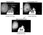
- the window is varied in the light emitting diode control section (that is, by detecting a brightness value while changing a partial region, preferably, such a partial region to the brightest portion in units of pixels) and saturation phenomenon in the bright portion. It is possible to fit this appearing part without saturation.
- the brightness detector further includes a region detector that detects brightness of a partial region on a pixel-by-pixel basis, and finds a region determined to be relatively brighter than the entire captured region, and the controller is configured to detect from the region detector.
- the duty ratio may be determined according to the brightness value of the obtained area to control the light emitting diode.
- FIG. 6 A specific example thereof is as shown in FIG. 6. That is, the tracking algorithm for finding the brightest section by finding only the brightest section and finding the brightness average within the section, there are several methods. A detailed example of this is shown in FIG.
- PWM signal square wave
- various types of algorithms may be applied to detect bright areas and control the lighting apparatus using the brightness thereof.
- the area detection unit detects a change in brightness of a region determined to be relatively bright or a change in relative position with respect to the entire screen compared to the entire captured region, and the control unit The control can be started when a certain value is exceeded. That is, when controlling the IR-LED at night, there is little movement in the camera, especially in an environment such as an office, a factory, or a school where the internal lighting device is turned off while the light is almost never turned on by the window. In such an environment, turning on the IR-LEDs brightly is a waste of their lifetime and power consumption.
- a change in brightness is detected from the area detection unit of the brightness detection unit implemented inside the camera, or an area in which the local window is judged to be relatively bright
- the IR-LED is operated to start the control.
- the lighting apparatus is switched to a wake-up mode for controlling to reach a predetermined target brightness.
- the camera of the present invention may be utilized as a night security device, and as described above, the light emitting diode is an infrared light emitting diode, and when the light emitting diode enters a control mode, the light source is increased in infrared light. It is recommended that the shooting mode be switched from color to black and white.
- the camera may transmit a message such as a warning to the subject.
- the information transfer medium may be a light emitting diode having a wavelength of a visible region.
- the light emitting diode having the wavelength of the visible region may be turned on even when switching to the wakeup mode.
- the light emitting diode is controlled only in a state where the exposure section (aperture, electronic shutter) for the imaging unit such as the CCD or CMOS is completely opened.
- the duty frequency and duty ratio for controlling the light emission amount of the light-emitting diode which are turned on are controlled by the control value of the automatic exposure controller and the automatic exposure controller to be determined by the brightness value input to the imaging unit. It is better to be faster than the frame period of moving images. The reason is that smaller products have power noise due to difficulty in power separation. This power noise causes horizontal noise in the resultant image when controlling the light emitting diode at the frame period. Because. Therefore, the faster the period for controlling the light emitting diode is, the less this noise is. More preferably, in order to duty control the light emitting diode, the duty cycle that forms the duty ratio is shorter than the input period of each line for one frame of the moving image. A specific example thereof is as shown in FIG. 7.
- the top of FIG. 7 represents one frame period as a frame period, and the following is a schematic diagram because 500 lines of signals are generally entered into one frame as a line period within the one frame.
- the period of the short line signal is shown.
- a signal having a period shorter than the line signal as a period for the duty cycle is applied as an internal counter for duty generation, whereby a square wave (PWM) signal for duty control is formed according to the duty ratio.
- PWM square wave
- the on state of the light emitting diode with the lowest duty ratio may be provided only for line 1, and as the amount of light increases, the light emitting diode on state with the lowest duty ratio is applied to more line signals.
- the duty ratio of each line may be gradually increased to increase the amount of light.
- the moving picture camera of the present invention it is possible to prevent saturation of bright parts of the image due to lighting of the lighting device (entering the control mode), and to maintain the maximum exposure time of the aperture and the electronic shutter even when the lighting device is turned on. It is possible to obtain an effect of enabling high quality image acquisition.
Landscapes
- Engineering & Computer Science (AREA)
- Multimedia (AREA)
- Signal Processing (AREA)
- Studio Devices (AREA)
- Exposure Control For Cameras (AREA)
Abstract
La présente invention concerne une caméra vidéo, et plus spécifiquement une caméra vidéo munie dune diode électroluminescente destinée à régler la luminosité dune image entrante. La caméra vidéo comprend : une unité de prise dimages destinée à obtenir un résultat de prise dimage ; une unité de détection de luminosité destinée à détecter la valeur de luminosité dune image ; et une unité de commande, qui détermine un moment auquel la diode électroluminescente passe à un mode de contrôle en adoptant, comme valeur dentrée, une valeur constante par rapport à au moins lune de valeurs de contrôle dexposition automatiques qui consistent en une valeur de contrôle diris destinée à ajuster lintensité de la lumière incidente par rapport à lunité de prise dimages, une valeur de contrôle dobturateur électronique destinée à contrôler le temps dexposition de lunité de prise dimages, une valeur de contrôle damplification de gain destinée à amplifier un signal électrique pour lintensité lumineuse, transmis par lunité de prise dimages et une combinaison de celles-ci, et qui détermine un facteur de marche sur la base de la valeur de luminosité détectée par lunité de détection de luminosité en mode de contrôle de la diode électroluminescente, contrôlant ainsi le cycle dutilisation de la diode électroluminescente. Ainsi, la présente invention empêche avantageusement toute saturation due à une partie lumineuse de limage lorsque lunité déclairage est allumée (comme par exemple en passant au mode de contrôle), et maintient un temps dexposition maximum de liris et de lobturateur électronique même lorsque lunité déclairage est allumée, permettant ainsi dacquérir une image de grande qualité pour une partie foncée de limage.
Applications Claiming Priority (2)
| Application Number | Priority Date | Filing Date | Title |
|---|---|---|---|
| KR1020090065173A KR101009366B1 (ko) | 2009-07-17 | 2009-07-17 | 동화상 카메라 |
| KR10-2009-0065173 | 2009-07-17 |
Publications (2)
| Publication Number | Publication Date |
|---|---|
| WO2011007996A2 true WO2011007996A2 (fr) | 2011-01-20 |
| WO2011007996A3 WO2011007996A3 (fr) | 2011-04-21 |
Family
ID=43449951
Family Applications (1)
| Application Number | Title | Priority Date | Filing Date |
|---|---|---|---|
| PCT/KR2010/004529 Ceased WO2011007996A2 (fr) | 2009-07-17 | 2010-07-13 | Caméra vidéo |
Country Status (2)
| Country | Link |
|---|---|
| KR (1) | KR101009366B1 (fr) |
| WO (1) | WO2011007996A2 (fr) |
Cited By (5)
| Publication number | Priority date | Publication date | Assignee | Title |
|---|---|---|---|---|
| WO2014118675A1 (fr) * | 2013-01-31 | 2014-08-07 | Koninklijke Philips N.V. | Organe de commande de dispositif d'éclairage, dispositif d'éclairage et procédé de commande de réglage de lumière d'un dispositif d'éclairage |
| CN112782907A (zh) * | 2020-12-30 | 2021-05-11 | 深圳市路远智能装备有限公司 | 一种基于光源控制器的具有实时速度检测方法及系统 |
| CN113401048A (zh) * | 2018-07-13 | 2021-09-17 | 神讯电脑(昆山)有限公司 | 车用取像装置及其设定方法 |
| CN113709936A (zh) * | 2021-08-26 | 2021-11-26 | 漳州立达信光电子科技有限公司 | 一种自定区域的恒光调节方法和系统 |
| CN114363525A (zh) * | 2022-03-17 | 2022-04-15 | 杭州灵西机器人智能科技有限公司 | Hdr快速自动成像方法、结构光相机、电子设备和存储介质 |
Families Citing this family (2)
| Publication number | Priority date | Publication date | Assignee | Title |
|---|---|---|---|---|
| KR101217785B1 (ko) * | 2011-04-14 | 2013-01-02 | 누비코 주식회사 | 조명 광도 조절이 가능한 비디오 카메라 장치 및 이의 조명 광도 조절방법 |
| CN107613191B (zh) * | 2017-08-01 | 2020-09-01 | 努比亚技术有限公司 | 一种拍照方法、设备及计算机可读存储介质 |
Family Cites Families (5)
| Publication number | Priority date | Publication date | Assignee | Title |
|---|---|---|---|---|
| JP2005150774A (ja) * | 2002-12-27 | 2005-06-09 | Casio Comput Co Ltd | 照明装置及び撮像装置 |
| KR20060124119A (ko) * | 2005-05-31 | 2006-12-05 | 주식회사 팬택 | 고속 카메라 프리뷰 방법 및 그 방법을 채택한 장치 |
| KR20070015315A (ko) * | 2005-07-30 | 2007-02-02 | 주식회사 팬택앤큐리텔 | 카메라 장착기기의 플래쉬 장치 |
| KR100718789B1 (ko) * | 2005-12-07 | 2007-05-16 | 매그나칩 반도체 유한회사 | 디지털 카메라를 이용한 이미지 촬상방법 |
| KR20070070822A (ko) * | 2005-12-29 | 2007-07-04 | 주식회사 팬택앤큐리텔 | 촬영 장치 및 카메라 제어 방법 |
-
2009
- 2009-07-17 KR KR1020090065173A patent/KR101009366B1/ko active Active
-
2010
- 2010-07-13 WO PCT/KR2010/004529 patent/WO2011007996A2/fr not_active Ceased
Cited By (8)
| Publication number | Priority date | Publication date | Assignee | Title |
|---|---|---|---|---|
| WO2014118675A1 (fr) * | 2013-01-31 | 2014-08-07 | Koninklijke Philips N.V. | Organe de commande de dispositif d'éclairage, dispositif d'éclairage et procédé de commande de réglage de lumière d'un dispositif d'éclairage |
| CN113401048A (zh) * | 2018-07-13 | 2021-09-17 | 神讯电脑(昆山)有限公司 | 车用取像装置及其设定方法 |
| CN113401048B (zh) * | 2018-07-13 | 2023-04-07 | 神讯电脑(昆山)有限公司 | 车用取像装置及其设定方法 |
| CN112782907A (zh) * | 2020-12-30 | 2021-05-11 | 深圳市路远智能装备有限公司 | 一种基于光源控制器的具有实时速度检测方法及系统 |
| CN113709936A (zh) * | 2021-08-26 | 2021-11-26 | 漳州立达信光电子科技有限公司 | 一种自定区域的恒光调节方法和系统 |
| CN113709936B (zh) * | 2021-08-26 | 2024-07-30 | 漳州立达信光电子科技有限公司 | 一种自定区域的恒光调节方法和系统 |
| CN114363525A (zh) * | 2022-03-17 | 2022-04-15 | 杭州灵西机器人智能科技有限公司 | Hdr快速自动成像方法、结构光相机、电子设备和存储介质 |
| CN114363525B (zh) * | 2022-03-17 | 2022-06-28 | 杭州灵西机器人智能科技有限公司 | Hdr快速自动成像方法、结构光相机、电子设备和存储介质 |
Also Published As
| Publication number | Publication date |
|---|---|
| WO2011007996A3 (fr) | 2011-04-21 |
| KR101009366B1 (ko) | 2011-01-19 |
Similar Documents
| Publication | Publication Date | Title |
|---|---|---|
| US7582871B2 (en) | Image pickup apparatus and a switching-over method for the same | |
| KR101486996B1 (ko) | 이동 검출 장치, 이동 검출 방법, 촬상 장치 및 감시시스템 | |
| US10136076B2 (en) | Imaging device, imaging system, and imaging method | |
| KR101009366B1 (ko) | 동화상 카메라 | |
| US8817107B2 (en) | Imaging device, imaging device control method and program | |
| CN103533252B (zh) | 一种昼夜模式自动切换的方法和装置 | |
| JP2021168465A (ja) | 夜間モード画像取得中に周囲光を評価するための方法 | |
| KR101169017B1 (ko) | 고해상도 씨모스 카메라가 적용된 주야간 자동 스위칭방식의 감시용 카메라 | |
| US9615031B2 (en) | Imaging device and scene determination method | |
| US20130063618A1 (en) | Image capture apparatus and control method thereof | |
| WO2018146945A1 (fr) | Dispositif de surveillance de corps en mouvement, et système de surveillance de corps en mouvement | |
| GB2459506A (en) | Surveillance Camera with Automatic Illumination | |
| US8169503B2 (en) | Image pickup apparatus and control method for selecting a flicker control method | |
| JP4328865B2 (ja) | 赤外線照明内蔵型監視用デイナイトカメラ | |
| JP2009005229A (ja) | 撮像装置および撮像装置の制御方法 | |
| JP7218116B2 (ja) | 撮像装置および撮像装置の制御方法 | |
| KR101971535B1 (ko) | 이미지 촬영 장치에서 자동 초점 조절 장치 및 방법 | |
| KR100978675B1 (ko) | 플래시를 이용한 촬영에서의 화이트밸런스 조정 방법 | |
| KR101295600B1 (ko) | 광역 역광 보정 장치 | |
| KR101217785B1 (ko) | 조명 광도 조절이 가능한 비디오 카메라 장치 및 이의 조명 광도 조절방법 | |
| JP2019092172A (ja) | 動体監視装置および動体監視システム | |
| JP2013126037A (ja) | 撮像装置および電子情報機器 | |
| KR20110045948A (ko) | 색 유동성 억제 장치 및 방법 | |
| US6618080B1 (en) | Auxiliary amplifier selection circuit for a CCD camera | |
| KR100933292B1 (ko) | 촬상장치 및 촬상장치의 모드 전환시 표시방법 |
Legal Events
| Date | Code | Title | Description |
|---|---|---|---|
| 121 | Ep: the epo has been informed by wipo that ep was designated in this application |
Ref document number: 10800007 Country of ref document: EP Kind code of ref document: A2 |
|
| NENP | Non-entry into the national phase |
Ref country code: DE |
|
| 122 | Ep: pct application non-entry in european phase |
Ref document number: 10800007 Country of ref document: EP Kind code of ref document: A2 |