WO2011024527A1 - Frp製駆動シャフト - Google Patents
Frp製駆動シャフト Download PDFInfo
- Publication number
- WO2011024527A1 WO2011024527A1 PCT/JP2010/059075 JP2010059075W WO2011024527A1 WO 2011024527 A1 WO2011024527 A1 WO 2011024527A1 JP 2010059075 W JP2010059075 W JP 2010059075W WO 2011024527 A1 WO2011024527 A1 WO 2011024527A1
- Authority
- WO
- WIPO (PCT)
- Prior art keywords
- frp
- drive shaft
- press
- serration
- cylinder
- Prior art date
- Legal status (The legal status is an assumption and is not a legal conclusion. Google has not performed a legal analysis and makes no representation as to the accuracy of the status listed.)
- Ceased
Links
Images




Classifications
-
- F—MECHANICAL ENGINEERING; LIGHTING; HEATING; WEAPONS; BLASTING
- F16—ENGINEERING ELEMENTS AND UNITS; GENERAL MEASURES FOR PRODUCING AND MAINTAINING EFFECTIVE FUNCTIONING OF MACHINES OR INSTALLATIONS; THERMAL INSULATION IN GENERAL
- F16C—SHAFTS; FLEXIBLE SHAFTS; ELEMENTS OR CRANKSHAFT MECHANISMS; ROTARY BODIES OTHER THAN GEARING ELEMENTS; BEARINGS
- F16C3/00—Shafts; Axles; Cranks; Eccentrics
- F16C3/02—Shafts; Axles
- F16C3/03—Shafts; Axles telescopic
-
- F—MECHANICAL ENGINEERING; LIGHTING; HEATING; WEAPONS; BLASTING
- F16—ENGINEERING ELEMENTS AND UNITS; GENERAL MEASURES FOR PRODUCING AND MAINTAINING EFFECTIVE FUNCTIONING OF MACHINES OR INSTALLATIONS; THERMAL INSULATION IN GENERAL
- F16C—SHAFTS; FLEXIBLE SHAFTS; ELEMENTS OR CRANKSHAFT MECHANISMS; ROTARY BODIES OTHER THAN GEARING ELEMENTS; BEARINGS
- F16C3/00—Shafts; Axles; Cranks; Eccentrics
- F16C3/02—Shafts; Axles
- F16C3/026—Shafts made of fibre reinforced resin
-
- F—MECHANICAL ENGINEERING; LIGHTING; HEATING; WEAPONS; BLASTING
- F16—ENGINEERING ELEMENTS AND UNITS; GENERAL MEASURES FOR PRODUCING AND MAINTAINING EFFECTIVE FUNCTIONING OF MACHINES OR INSTALLATIONS; THERMAL INSULATION IN GENERAL
- F16C—SHAFTS; FLEXIBLE SHAFTS; ELEMENTS OR CRANKSHAFT MECHANISMS; ROTARY BODIES OTHER THAN GEARING ELEMENTS; BEARINGS
- F16C3/00—Shafts; Axles; Cranks; Eccentrics
- F16C3/02—Shafts; Axles
- F16C3/023—Shafts; Axles made of several parts, e.g. by welding
-
- F—MECHANICAL ENGINEERING; LIGHTING; HEATING; WEAPONS; BLASTING
- F16—ENGINEERING ELEMENTS AND UNITS; GENERAL MEASURES FOR PRODUCING AND MAINTAINING EFFECTIVE FUNCTIONING OF MACHINES OR INSTALLATIONS; THERMAL INSULATION IN GENERAL
- F16D—COUPLINGS FOR TRANSMITTING ROTATION; CLUTCHES; BRAKES
- F16D1/00—Couplings for rigidly connecting two coaxial shafts or other movable machine elements
- F16D1/02—Couplings for rigidly connecting two coaxial shafts or other movable machine elements for connecting two abutting shafts or the like
-
- F—MECHANICAL ENGINEERING; LIGHTING; HEATING; WEAPONS; BLASTING
- F16—ENGINEERING ELEMENTS AND UNITS; GENERAL MEASURES FOR PRODUCING AND MAINTAINING EFFECTIVE FUNCTIONING OF MACHINES OR INSTALLATIONS; THERMAL INSULATION IN GENERAL
- F16D—COUPLINGS FOR TRANSMITTING ROTATION; CLUTCHES; BRAKES
- F16D1/00—Couplings for rigidly connecting two coaxial shafts or other movable machine elements
- F16D1/02—Couplings for rigidly connecting two coaxial shafts or other movable machine elements for connecting two abutting shafts or the like
- F16D1/04—Couplings for rigidly connecting two coaxial shafts or other movable machine elements for connecting two abutting shafts or the like with clamping hub; with hub and longitudinal key
-
- F—MECHANICAL ENGINEERING; LIGHTING; HEATING; WEAPONS; BLASTING
- F16—ENGINEERING ELEMENTS AND UNITS; GENERAL MEASURES FOR PRODUCING AND MAINTAINING EFFECTIVE FUNCTIONING OF MACHINES OR INSTALLATIONS; THERMAL INSULATION IN GENERAL
- F16D—COUPLINGS FOR TRANSMITTING ROTATION; CLUTCHES; BRAKES
- F16D1/00—Couplings for rigidly connecting two coaxial shafts or other movable machine elements
- F16D1/06—Couplings for rigidly connecting two coaxial shafts or other movable machine elements for attachment of a member on a shaft or on a shaft-end
-
- F—MECHANICAL ENGINEERING; LIGHTING; HEATING; WEAPONS; BLASTING
- F16—ENGINEERING ELEMENTS AND UNITS; GENERAL MEASURES FOR PRODUCING AND MAINTAINING EFFECTIVE FUNCTIONING OF MACHINES OR INSTALLATIONS; THERMAL INSULATION IN GENERAL
- F16D—COUPLINGS FOR TRANSMITTING ROTATION; CLUTCHES; BRAKES
- F16D1/00—Couplings for rigidly connecting two coaxial shafts or other movable machine elements
- F16D1/06—Couplings for rigidly connecting two coaxial shafts or other movable machine elements for attachment of a member on a shaft or on a shaft-end
- F16D1/08—Couplings for rigidly connecting two coaxial shafts or other movable machine elements for attachment of a member on a shaft or on a shaft-end with clamping hub; with hub and longitudinal key
- F16D1/0852—Couplings for rigidly connecting two coaxial shafts or other movable machine elements for attachment of a member on a shaft or on a shaft-end with clamping hub; with hub and longitudinal key with radial clamping between the mating surfaces of the hub and shaft
- F16D1/0858—Couplings for rigidly connecting two coaxial shafts or other movable machine elements for attachment of a member on a shaft or on a shaft-end with clamping hub; with hub and longitudinal key with radial clamping between the mating surfaces of the hub and shaft due to the elasticity of the hub (including shrink fits)
-
- F—MECHANICAL ENGINEERING; LIGHTING; HEATING; WEAPONS; BLASTING
- F16—ENGINEERING ELEMENTS AND UNITS; GENERAL MEASURES FOR PRODUCING AND MAINTAINING EFFECTIVE FUNCTIONING OF MACHINES OR INSTALLATIONS; THERMAL INSULATION IN GENERAL
- F16D—COUPLINGS FOR TRANSMITTING ROTATION; CLUTCHES; BRAKES
- F16D1/00—Couplings for rigidly connecting two coaxial shafts or other movable machine elements
- F16D1/06—Couplings for rigidly connecting two coaxial shafts or other movable machine elements for attachment of a member on a shaft or on a shaft-end
- F16D1/08—Couplings for rigidly connecting two coaxial shafts or other movable machine elements for attachment of a member on a shaft or on a shaft-end with clamping hub; with hub and longitudinal key
- F16D1/0852—Couplings for rigidly connecting two coaxial shafts or other movable machine elements for attachment of a member on a shaft or on a shaft-end with clamping hub; with hub and longitudinal key with radial clamping between the mating surfaces of the hub and shaft
- F16D1/087—Couplings for rigidly connecting two coaxial shafts or other movable machine elements for attachment of a member on a shaft or on a shaft-end with clamping hub; with hub and longitudinal key with radial clamping between the mating surfaces of the hub and shaft due to other loading elements in the hub or shaft
-
- F—MECHANICAL ENGINEERING; LIGHTING; HEATING; WEAPONS; BLASTING
- F16—ENGINEERING ELEMENTS AND UNITS; GENERAL MEASURES FOR PRODUCING AND MAINTAINING EFFECTIVE FUNCTIONING OF MACHINES OR INSTALLATIONS; THERMAL INSULATION IN GENERAL
- F16C—SHAFTS; FLEXIBLE SHAFTS; ELEMENTS OR CRANKSHAFT MECHANISMS; ROTARY BODIES OTHER THAN GEARING ELEMENTS; BEARINGS
- F16C2326/00—Articles relating to transporting
- F16C2326/01—Parts of vehicles in general
- F16C2326/06—Drive shafts
-
- F—MECHANICAL ENGINEERING; LIGHTING; HEATING; WEAPONS; BLASTING
- F16—ENGINEERING ELEMENTS AND UNITS; GENERAL MEASURES FOR PRODUCING AND MAINTAINING EFFECTIVE FUNCTIONING OF MACHINES OR INSTALLATIONS; THERMAL INSULATION IN GENERAL
- F16D—COUPLINGS FOR TRANSMITTING ROTATION; CLUTCHES; BRAKES
- F16D1/00—Couplings for rigidly connecting two coaxial shafts or other movable machine elements
- F16D1/10—Quick-acting couplings in which the parts are connected by simply bringing them together axially
- F16D2001/102—Quick-acting couplings in which the parts are connected by simply bringing them together axially the torque is transmitted via polygon shaped connections
-
- F—MECHANICAL ENGINEERING; LIGHTING; HEATING; WEAPONS; BLASTING
- F16—ENGINEERING ELEMENTS AND UNITS; GENERAL MEASURES FOR PRODUCING AND MAINTAINING EFFECTIVE FUNCTIONING OF MACHINES OR INSTALLATIONS; THERMAL INSULATION IN GENERAL
- F16D—COUPLINGS FOR TRANSMITTING ROTATION; CLUTCHES; BRAKES
- F16D1/00—Couplings for rigidly connecting two coaxial shafts or other movable machine elements
- F16D1/10—Quick-acting couplings in which the parts are connected by simply bringing them together axially
- F16D2001/103—Quick-acting couplings in which the parts are connected by simply bringing them together axially the torque is transmitted via splined connections
Definitions
- the present invention relates to a drive shaft made of FRP used for, for example, a propeller shaft (drive shaft) of a vehicle.
- the FRP drive shaft is formed by joining metal end joints to both ends of an FRP (Fiber Reinforced Plastics) cylinder, and has the advantage of being lightweight.
- FRP Fiber Reinforced Plastics
- Patent Document 1 proposes a new fiber structure on the FRP cylinder side on the premise of a structure in which the FRP cylinder and the end joint are coupled via a fastening member that penetrates both ends in the radial direction.
- stress concentration occurs in the penetrating portion, and the FRP cylinder or the penetrating member is still easily damaged.
- Patent Document 2 proposes that the end joint is composed of a metal yoke that is inserted and fixed to the FRP cylinder, and an outer collar that is fitted to the outer periphery of the FRP cylinder and fixed to the metal yoke by welding.
- the metal yoke and the outer collar there is a high possibility that the FRP cylinder will be damaged by heat, and it is quite difficult to obtain the mechanical strength as described in this document.
- Patent Document 3 has a structure in which an intermediate cylindrical member is interposed between the FRP cylinder and the end joint, the outer peripheral surface of the intermediate cylindrical member is serrated to the FRP cylinder, and the inner peripheral surface is splined to the end joint. is suggesting.
- the FRP cylinder itself is highly likely to be damaged.
- the FRP cylinder is composed of a plurality of FRP layers in which a plurality of prepregs obtained by impregnating carbon fibers in a thermosetting resin sheet are wound into a cylindrical shape and thermally cured, a delamination phenomenon occurs between the layers, There is a risk of damage.
- the present invention has an object to obtain an FRP drive shaft that can increase the coupling strength between the FRP cylinder and the metal joint at the end, and obtain a high transmission torque, based on the above problem awareness.
- the present invention relates to a drive shaft made of FRP in which metal end joints are coupled to both ends of an FRP cylinder, a press-fit joint having a serration portion that is press-fitted into the FRP cylinder, and the FRP cylinder.
- the cylindrical outer collar is fixed to the outer periphery of the outer peripheral portion, and the press-fit joint and the cylindrical outer collar are formed with non-circular engaging portions that engage with each other and transmit rotation.
- the non-circular engaging portion is preferably composed of an oval hole and an oval cross-section shaft portion (a hole portion and an axial portion having a pair of parallel flat portions).
- a rod-like press-fit joint with a serration portion having a maximum diameter is used as the press-fit joint
- the cylindrical outer collar includes a tubular portion fixed to the outer peripheral surface of the FRP cylinder, and the tubular portion. And an end face portion located at the end portion.
- a non-circular engagement hole having a size that fits within the outer diameter of the FRP cylinder is formed in the end face portion, and a non-circular cross-section shaft portion that engages with the non-circular engagement hole is formed in the press-fit joint.
- the cylindrical outer collar is fitted and fixed to the outer peripheral surface of the FRP cylinder, and at the same time, the non-circular cross-section shaft portion of the press-fit joint is attached to the non-circular outer collar.
- a circular cross-sectional hole can be fitted.
- the cylindrical outer collar is provided with an end surface portion having a diameter larger than that of the FRP cylinder, and the end surface portion of the FRP cylinder is provided.
- a non-circular engagement hole having a size protruding from the outer diameter is formed.
- the press-fit joint is formed with a non-circular cross-section shaft portion that is interposed between the serration portion and the large-diameter flange portion and engages with the non-circular engagement hole.
- the serration portion of the press-fit joint is press-fitted into the FRP cylinder, and at the same time, the non-circular sectional shaft portion is engaged with the non-circular engagement of the cylindrical outer collar. Fit into the hole.
- the press-fit joint having a serration portion and a large-diameter flange portion can be composed of one member, or can be composed of two members, a large-diameter flange member and a serration shaft member, which are connected later.
- the axial length of the cylindrical portion of the cylindrical outer collar located outside the FRP cylinder should be substantially the same as or longer than the effective serration length of the serration portion located inside the FRP cylinder. preferable. In the latter case, when the portion of the cylindrical outer collar where the serration portion does not exist and the FRP cylinder are joined by a radial through rivet (blind rivet), the FRP cylinder and the cylindrical outer collar are joined. Strength can be increased.
- the outer collar may be composed of a full cylindrical member, or may be composed of two divided outer collars having a semi-cylindrical cross section and a coupling member that couples the two divided outer collars. According to this configuration, since it is not necessary to pass the inner peripheral surface of the cylindrical outer collar through the press-fit joint from the axial direction, assembly is easy.
- a reinforcing FRP layer containing a fiber component in the circumferential direction is provided in a cylindrical shape on the outer periphery of both ends of the FRP cylinder in order to increase the resistance and strength against press-fitting of the serration part.
- the FRP drive shaft of the present invention can be applied regardless of the configuration of the FRP cylinder, the resin (for example, thermoplastic resin), and the fiber, and in particular, a plurality of carbon reinforced fibers impregnated in a thermosetting resin sheet.
- the resin for example, thermoplastic resin
- the fiber for example, a plurality of carbon reinforced fibers impregnated in a thermosetting resin sheet.
- the end joint is composed of a press-fit joint having a serration portion press-fitted into the FRP cylinder, and a cylindrical outer collar fixed to the outer periphery of the FRP cylinder. Since the cylindrical outer collar is formed with a non-circular engaging portion that engages with each other and transmits rotation, when torque is transmitted between the end joint and the FRP cylinder, the FRP cylinder is simultaneously in and out of the FRP cylinder. Torque is applied. For this reason, the damage resulting from the load difference (torque difference) between the inside and outside applied to the FRP cylinder hardly occurs.
- the FRP cylinder is composed of a plurality of FRP layers in which a plurality of prepregs are wound into a cylindrical shape and thermally cured, a large peeling load is not applied to the plurality of FRP layers, so that peeling damage can be prevented. it can.
- FIG. 5 is a cross-sectional view taken along line V-V in FIG. 4, showing a non-circular engagement portion between a press-fit joint and a cylindrical outer collar. It is a fragmentary sectional view of the modification of a cylindrical outer collar, (A) is a figure showing an exploded state, and (B) is a figure showing an assembly state.
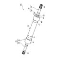
- FIG. 1 to 5 show the configuration of an FRP drive shaft 100 according to Embodiment 1 of the present invention.
- the FRP drive shaft 100 is formed by connecting end joints 20 made of metal to both ends of the FRP cylinder 10.
- the two end joints 20 have the same configuration, the same reference numerals are used for description.
- the FRP cylinder 10 is a plurality of CFRP (Carbon Fiber Reinforced Plastics) layers in which a plurality of prepregs obtained by impregnating carbon reinforced fibers in a thermosetting resin sheet are wound into a cylindrical shape and thermally cured. Consists of.
- CFRP Carbon Fiber Reinforced Plastics
- the end joint 20 includes a press-fit joint 30 having a serration portion 31 that is press-fit into the inner peripheral surface 11 of the FRP cylinder 10, and a cylindrical outer collar 40 that is bonded and fixed to the outer peripheral surface 12 of the FRP cylinder 10. ing. Reinforcing FRP layers 13 including a fiber component in the circumferential direction are formed in a cylindrical shape at both ends of the FRP cylinder 10 in order to increase the resistance and strength against press-fitting of the serration part 31.
- the press-fit joint 30 is a rod-type press-fit joint with a serrated portion 31 having a maximum diameter.
- a non-circular cross-section shaft portion (oval cross-section shaft portion) 32 is formed following the serration portion 31, and is opposite to the serration portion 31.
- a rotation transmission portion (connection serration portion) 33 is formed at the end on the side.
- the cylindrical outer collar 40 includes a cylindrical portion 41 that is bonded and fixed to the outer peripheral surface 12 of the FRP cylinder 10, and an end surface portion 42 that is positioned at an end portion of the cylindrical portion 41.
- the non-circular cross-section shaft portion 32 of the press-fit joint 30 and the non-circular engagement hole 43 of the cylindrical outer collar 40 constitute a non-circular engagement portion that engages with each other and transmits rotation.
- the cylindrical outer collar 40 is fitted and fixed to the outer peripheral surface 12 of the FRP cylinder 10. At the same time, it is assembled by fitting the non-circular engagement hole 43 of the cylindrical outer collar 40 into the non-circular cross-section shaft portion 32 of the press-fit joint 30 (FIGS. 1 to 4).
- the axial length D of the cylindrical portion 41 of the cylindrical outer collar 40 located outside the FRP cylinder 10 is the effective serration length d of the serration portion 31 located inside the FRP cylinder 10. Is almost the same.
- the effective serration length means the axial length of the portion of the serration portion 31 that meshes with the inner peripheral surface 11 of the FRP cylinder 10 excluding the tapered portion at the tip.
- the rotation transmission portions 33 at both ends of the press-fit joint 30 are connected to an engine rotation portion and a differential gear (not shown), respectively, and the FRP drive shaft is provided.
- rotational torque is applied to 100, rotational torque is transmitted between the end joint 20 and the FRP cylinder 10.
- the serration portion 31 of the press-fit joint 30 is press-fitted into the inner peripheral surface 11 of the FRP cylinder 10, and the cylindrical outer collar 40 is bonded and fixed to the outer peripheral surface 12 of the FRP cylinder 10, so Since the shaft portion 32 and the non-circular engagement hole 43 of the cylindrical outer collar 40 engage with each other to form a non-circular engagement portion that transmits rotation, the coupling strength between the FRP cylinder 10 and the end joint 20 is increased. And high transmission torque can be obtained. Further, since rotational torque is simultaneously applied to the inside and outside of the FRP cylinder 10, damage due to a load difference (torque difference) between the inside and outside of the FRP cylinder 10 is unlikely to occur.
- the FRP cylinder 10 is composed of a plurality of FRP layers obtained by winding a plurality of prepregs into a cylindrical shape and thermosetting, a large peeling load is not applied to the plurality of FRP layers, thereby preventing peeling damage. Can do.
- the cylindrical outer collar 40 is composed of two divided outer collars 44 and 45 having a semi-cylindrical cross section, and ring members (joining members) 46 and 47 that couple the two divided outer collars 44 and 45.
- a modification is shown. That is, after the serration portion 31 of the press-fit joint 30 is press-fitted into the inner peripheral surface 11 of the FRP cylinder 10, the divided outer collars 44 and 45 are butted against the outer peripheral surface 12 of the FRP cylinder 10 so as to wrap in the radial direction.
- Ring members (coupling members) 46 and 47 previously fitted on the outer periphery of the FRP cylinder 10 are fitted into the small end portions 44a and 44b of the collar 44 and the small end portions 45a and 45b of the split outer collar 45, respectively. .
- the split outer collars 44 and 45 may be further bonded or welded. As described above, the split outer collars 44 and 45 and the ring members 46 and 47 are assembled to complete the cylindrical outer collar 40. According to this configuration, since it is not necessary to pass the inner peripheral surface of the cylindrical outer collar 40 through the press-fit joint 30 from the axial direction, assembly is easy.
- FIG. 7 is a cross-sectional view showing a coupling portion between the FRP cylinder 10 and the end joint 20 ′ of the FRP drive shaft 200 according to Embodiment 2 of the present invention.
- the same components as those in the first embodiment are denoted by the same reference numerals, and the description thereof is omitted.
- the press-fit joint 50 of the present embodiment has a serration portion 51 that is press-fit into the inner peripheral surface 11 of the FRP cylinder 10, and a large-diameter flange portion 52 that is larger in diameter than the serration portion 51 following the serration portion 51. ing.
- the press-fit joint 50 is formed with a non-circular cross-section shaft portion (oval cross-section shaft portion) 53 interposed between the serration portion 51 and the large-diameter flange portion 52.
- the press-fit joint 50 includes two members, a serration shaft member having a serration portion 51 and a large diameter flange member having a large diameter flange portion 52 coupled to the serration shaft member.
- the press-fit joint 50 can also be configured from a single member integrally having a serration portion 51 and a large-diameter flange portion 52.
- the cylindrical outer collar 60 has a cylindrical portion 61 that is fixed to the outer peripheral surface 12 of the FRP cylinder 10 and an end surface portion 62 that is located at the end of the cylindrical portion 61.
- a circular engagement hole (oval hole) 63 is formed.
- the end surface portion 62 is formed to have a larger diameter than the FRP cylinder 10, and the non-circular engagement hole 63 is formed so as to protrude from the outer diameter of the FRP cylinder 10.
- the press-fit joint 50 is provided with a large-diameter flange portion 52 having a diameter larger than that of the serration portion 51, the non-circular cross-section shaft portion 53 of the press-fit joint 50 and the cylindrical outer collar are provided.
- the 60 non-circular engaging holes 63 can be configured as non-circular engaging portions that engage with each other to transmit rotation.
- the serration portion 51 of the press-fit joint 50 is press-fitted into the inner peripheral surface 11 of the FRP cylinder 10.
- the non-circular cross-section shaft portion 53 of the press-fit joint 50 is assembled into the non-circular engagement hole 63 of the cylindrical outer collar.
- the axial length D of the cylindrical portion 61 of the cylindrical outer collar 60 located outside the FRP cylinder 10 is the effective serration length d of the serration portion 51 located inside the FRP cylinder 10. Is almost the same.
- the large-diameter flange portions 52 at both ends are connected to the engine rotation portion and the differential gear, respectively.
- the axial length D of the cylindrical portion 61 of the cylindrical outer collar 60 positioned outside the FRP cylinder 10 is larger than the effective serration length d of the serration portion 51 positioned inside the FRP cylinder 10. It may be longer.
- the cylindrical portion 61 of the cylindrical outer collar 60 is joined to the FRP cylinder 10 with a radial through rivet (blind rivet) 70 in a portion where the serration portion 51 does not exist inside. Then, higher strength can be obtained.
- the cylindrical portion of the cylindrical outer collar 60 may be a tapered cylindrical portion 61 ′ that becomes thicker toward the end surface portion 62 (cone. Outer color).
- the FRP cylinder is a multilayer cylinder created by the prepreg method, and the effect of preventing delamination in the case of the multilayer cylinder is obtained.
- the present invention can be applied regardless of the configuration and manufacturing method of the FRP cylinder.
- any configuration FRP cylinder manufactured by the filament winding method or the like is applicable.
- the FRP drive shaft according to the present invention can be widely used in various industrial fields such as a vehicle propeller shaft (drive shaft).
Landscapes
- Engineering & Computer Science (AREA)
- General Engineering & Computer Science (AREA)
- Mechanical Engineering (AREA)
- Ocean & Marine Engineering (AREA)
- Shafts, Cranks, Connecting Bars, And Related Bearings (AREA)
Abstract
Description
図1ないし図5は、本発明の実施の形態1に係るFRP製駆動シャフト100の構成を示している。FRP製駆動シャフト100は、FRP円筒10の両端部に、金属製の端部ジョイント20を結合してなる。本実施形態では、2つの端部ジョイント20は同一の構成を有しているため同一の符号を付して説明する。
図7は、本発明の実施の形態2に係るFRP製駆動シャフト200のFRP円筒10と端部ジョイント20’の結合部を示す断面図である。実施の形態1と同一の構成要素には同一の符号を付し、その説明を省略する。
10 FRP円筒
11 円筒内周面
12 円筒外周面
13 補強FRP層
20 端部ジョイント
30 圧入ジョイント
31 セレーション部
32 非円形断面軸部(小判状断面軸部)
33 回転伝達部(接続セレーション部)
40 円筒状アウタカラー
41 筒状部
42 端面部
43 非円形係合穴(小判状穴)
44 45 分割アウタカラー
46 47 リング部材(結合部材)
45a 45b 46a 46b 端部小径部
200 FRP製駆動シャフト
20’ 端部ジョイント
50 圧入ジョイント
51 セレーション部
52 大径フランジ部
53 非円形断面軸部(小判状断面軸部)
60 円筒状アウタカラー
61 筒状部
61’ テーパ状筒状部
62 端面部
63 非円形係合穴(小判状穴)
70 貫通リベット(ブラインドリベット)
Claims (12)
- FRP円筒の両端部に、金属製の端部ジョイントを結合してなるFRP製駆動シャフトにおいて、
上記端部ジョイントを、FRP円筒内に圧入されるセレーション部を有する圧入ジョイントと、FRP円筒の外周に固定される円筒状アウタカラーとから構成し、この圧入ジョイントと円筒状アウタカラーとに、互いに係合して回転を伝達する非円形係合部をそれぞれ形成したことを特徴とするFRP製駆動シャフト。 - 請求の範囲第1項記載のFRP製駆動シャフトにおいて、
上記非円形係合部は、小判状穴と小判状断面軸部からなるFRP製駆動シャフト。 - 請求の範囲第1項又は第2項記載のFRP製駆動シャフトにおいて、
上記圧入ジョイントはセレーション部の径が最大径の棒状圧入ジョイントからなり、円筒状アウタカラーは、FRP円筒の外周面に固定される筒状部と、この筒状部の端部に位置する端面部とを有していて、この端面部にFRP円筒の外径内に収まる大きさの非円形係合穴が形成されており、上記圧入ジョイントには、セレーション部に続けて、上記円筒状アウタカラーの非円形係合穴に係合する非円形断面軸部が形成されているFRP製駆動シャフト。 - 請求の範囲第1項又は第2項記載のFRP製駆動シャフトにおいて、
上記圧入ジョイントは、セレーション部に続けて該セレーション部より大径のフランジ部を有し、円筒状アウタカラーは、FRP円筒より大径の端面部を備えていて、この端面部に、FRP円筒の外径からはみ出す大きさの非円形係合穴が形成されており、上記圧入ジョイントには、上記セレーション部と大径フランジ部の間に介在させて、この非円形係合穴に係合する非円形断面軸部が形成されているFRP製駆動シャフト。 - 請求の範囲第4項記載のFRP製駆動シャフトにおいて、
上記圧入ジョイントは、セレーション部と大径フランジ部を一体に有する一部材からなるFRP製駆動シャフト。 - 請求の範囲第4項記載のFRP製駆動シャフトにおいて、
上記圧入ジョイントは、セレーション部を有するセレーション軸部材と、このセレーション軸部材に結合される大径フランジ部材とからなるFRP製駆動シャフト。 - 請求の範囲第3項乃至第6項のいずれか1項記載のFRP製駆動シャフトにおいて、
上記FRP円筒の外側に位置する上記円筒状アウタカラーの筒状部の軸方向長は、上記FRP円筒の内側に位置する上記セレーション部の有効セレーション長と略同一であるFRP製駆動シャフト。 - 請求の範囲第3項乃至第6項のいずれか1項記載のFRP製駆動シャフトにおいて、
上記FRP円筒の外側に位置する上記円筒状アウタカラーの筒状部の軸方向長は、上記FRP円筒の内側に位置する上記セレーション部の有効セレーション長よりも長いFRP製駆動シャフト。 - 請求の範囲第8項記載のFRP製駆動シャフトにおいて、
上記円筒状アウタカラーの筒状部は、内側にセレーション部が存在しない部分において、上記FRP円筒と径方向の貫通リベットで結合されているFRP製駆動シャフト。 - 請求の範囲第1項乃至第9項のいずれか1項記載のFRP製駆動シャフトにおいて、
上記円筒状アウタカラーは、断面半円筒状の2つの分割アウタカラーと、この2つの分割アウタカラーを結合する結合部材とからなるFRP製駆動シャフト。 - 請求の範囲第1項乃至第10項のいずれか1項記載のFRP製駆動シャフトにおいて、
上記FRP円筒の両端部外周には、周方向の繊維成分を含む補強FRP層が円筒状に形成されているFRP製駆動シャフト。 - 請求の範囲第1項乃至第11項のいずれか1項記載のFRP製駆動シャフトにおいて、
上記FRP円筒は、炭素強化繊維を熱硬化性樹脂シート中に含浸させてなる複数のプリプレグを筒状に巻回して熱硬化させた複数のCFRP層からなるFRP製駆動シャフト。
Priority Applications (3)
| Application Number | Priority Date | Filing Date | Title |
|---|---|---|---|
| US13/393,052 US8876614B2 (en) | 2009-08-31 | 2010-05-28 | FRP drive shaft |
| CN201080036241.1A CN102472310B (zh) | 2009-08-31 | 2010-05-28 | Frp制驱动轴 |
| EP10811580.9A EP2474751B1 (en) | 2009-08-31 | 2010-05-28 | Frp-made drive shaft |
Applications Claiming Priority (2)
| Application Number | Priority Date | Filing Date | Title |
|---|---|---|---|
| JP2009-199988 | 2009-08-31 | ||
| JP2009199988A JP5683798B2 (ja) | 2009-08-31 | 2009-08-31 | Frp製駆動シャフト |
Publications (1)
| Publication Number | Publication Date |
|---|---|
| WO2011024527A1 true WO2011024527A1 (ja) | 2011-03-03 |
Family
ID=43627640
Family Applications (1)
| Application Number | Title | Priority Date | Filing Date |
|---|---|---|---|
| PCT/JP2010/059075 Ceased WO2011024527A1 (ja) | 2009-08-31 | 2010-05-28 | Frp製駆動シャフト |
Country Status (7)
| Country | Link |
|---|---|
| US (1) | US8876614B2 (ja) |
| EP (1) | EP2474751B1 (ja) |
| JP (1) | JP5683798B2 (ja) |
| KR (1) | KR20120040715A (ja) |
| CN (1) | CN102472310B (ja) |
| TW (1) | TWI527716B (ja) |
| WO (1) | WO2011024527A1 (ja) |
Families Citing this family (28)
| Publication number | Priority date | Publication date | Assignee | Title |
|---|---|---|---|---|
| DE102011053342A1 (de) * | 2011-09-07 | 2013-03-07 | Technische Universität Darmstadt | Drehwelle und Anschlusselement |
| FR2997034B1 (fr) * | 2012-10-18 | 2015-05-01 | Epsilon Composite | Procede de collage de deux pieces soumises a des efforts de traction, pieces collees obtenues |
| KR101428284B1 (ko) * | 2012-12-12 | 2014-08-08 | 현대자동차주식회사 | 프로펠러 샤프트 |
| DE102013204181A1 (de) | 2013-03-12 | 2014-09-18 | Bayerische Motoren Werke Aktiengesellschaft | Anschlussvorrichtung für eine Welle |
| JP6159572B2 (ja) * | 2013-05-13 | 2017-07-05 | 本田技研工業株式会社 | トルク伝達装置 |
| DE102013009497A1 (de) * | 2013-06-05 | 2014-12-11 | Daimler Ag | Teleskopierbare Antriebswelle |
| KR101459959B1 (ko) * | 2013-10-17 | 2014-11-12 | 현대자동차주식회사 | 차량용 프로펠러 샤프트 |
| CN103950313A (zh) * | 2014-04-29 | 2014-07-30 | 李赵和 | 一种书帖书背上胶辊 |
| US10138925B2 (en) | 2014-05-26 | 2018-11-27 | Fujikura Rubber Ltd. | FRP drive shaft |
| WO2016088913A1 (ko) * | 2014-12-03 | 2016-06-09 | 원광이엔텍 주식회사 | 탄소섬유 강화 플라스틱을 적용한 드라이브 샤프트 어셈블리 |
| WO2016112451A1 (en) * | 2015-01-12 | 2016-07-21 | Halliburton Energy Services, Inc. | Connection for transmitting torque and axial forces |
| JP6427602B2 (ja) * | 2015-01-29 | 2018-11-21 | 本田技研工業株式会社 | トルク伝達装置 |
| CN105020277A (zh) * | 2015-07-13 | 2015-11-04 | 苏州柏德纳科技有限公司 | 一种连接轴 |
| CN105020276A (zh) * | 2015-07-13 | 2015-11-04 | 苏州柏德纳科技有限公司 | 一种新型连接轴 |
| US9909624B2 (en) | 2015-09-22 | 2018-03-06 | Rohr, Inc. | Composite driveshaft for a rotary system |
| JP6212577B2 (ja) * | 2016-02-10 | 2017-10-11 | 本田技研工業株式会社 | 連結シャフトおよび連結シャフトの製造方法 |
| US10344794B2 (en) | 2016-11-18 | 2019-07-09 | Dana Automotive Systems Group, Llc | Open composite shaft |
| DE102017223304B4 (de) * | 2017-12-19 | 2023-08-24 | Bayerische Motoren Werke Aktiengesellschaft | Kraftfahrzeugantriebswelle und Verfahren zu deren Herstellung |
| JP7217587B2 (ja) | 2017-12-27 | 2023-02-03 | Ntn株式会社 | 動力伝達用シャフト |
| KR102208388B1 (ko) | 2018-08-23 | 2021-01-27 | 효림산업 주식회사 | 자동차용 cfrp 드라이브샤프트 제조방법 |
| US12179913B2 (en) | 2018-08-24 | 2024-12-31 | Hamilton Sundstrand Corporation | Ballistic resistant drive shaft |
| GB2583538B (en) * | 2019-05-03 | 2024-02-28 | Polar Tech Management Group Limited | Connector arrangement |
| US11519454B2 (en) | 2019-07-24 | 2022-12-06 | Goodrich Corporation | Hybrid metallic/composite tube design to transfer bending, axial, and flexural shear |
| RU2724035C1 (ru) * | 2019-10-30 | 2020-06-18 | Федеральное государственное унитарное предприятие "Центральный аэрогидродинамический институт имени профессора Н.Е. Жуковского" (ФГУП "ЦАГИ") | Композитный стержневой конструкционный элемент |
| EP3859175B1 (en) | 2020-01-29 | 2025-09-17 | Crompton Technology Group Limited | Composite end connections |
| US11859664B2 (en) * | 2021-11-18 | 2024-01-02 | Spm Oil & Gas Inc. | Multi-piece pinion shaft assembly |
| CN114233761A (zh) * | 2022-01-24 | 2022-03-25 | 沈阳工业大学 | 一种碳纤维复合材料传动轴的连接装置 |
| DE102024102306A1 (de) * | 2024-01-26 | 2025-07-31 | Tk Elevator Innovation And Operations Gmbh | Mehrteilige Antriebswelle für Treibmittel einer Aufzugsanlage |
Citations (11)
| Publication number | Priority date | Publication date | Assignee | Title |
|---|---|---|---|---|
| JPS5977505U (ja) * | 1982-11-18 | 1984-05-25 | 光洋精工株式会社 | ロ−ルカツプリング |
| JPS59126115A (ja) * | 1983-01-07 | 1984-07-20 | Kawasaki Heavy Ind Ltd | 軸継手 |
| JPH0191118U (ja) | 1987-12-08 | 1989-06-15 | ||
| JPH04136522A (ja) * | 1990-09-27 | 1992-05-11 | Mazda Motor Corp | 動力伝達軸の製造方法 |
| JPH04181021A (ja) * | 1990-11-13 | 1992-06-29 | Mazda Motor Corp | プロペラシャフト構造 |
| JPH0632726U (ja) | 1992-10-02 | 1994-04-28 | 住友金属工業株式会社 | 繊維強化プラスチック製駆動軸 |
| JPH0783240A (ja) * | 1993-09-13 | 1995-03-28 | Toho Rayon Co Ltd | Frp製シャフトと継手との接合構造および接合方法 |
| JP2001090764A (ja) * | 1999-09-20 | 2001-04-03 | Nippon Petrochem Co Ltd | 衝撃エネルギー吸収デバイス |
| JP2003237396A (ja) * | 2002-02-20 | 2003-08-27 | Toyota Industries Corp | Frp製プロペラシャフト |
| JP2004308700A (ja) | 2003-04-02 | 2004-11-04 | Toyota Motor Corp | 繊維強化プラスチック製プロペラシャフト |
| JP2006103032A (ja) * | 2004-10-01 | 2006-04-20 | Toray Ind Inc | Frp製円筒体と金属製継ぎ手との接合体 |
Family Cites Families (21)
| Publication number | Priority date | Publication date | Assignee | Title |
|---|---|---|---|---|
| JPS5531309Y2 (ja) * | 1975-09-13 | 1980-07-25 | ||
| US4248062A (en) * | 1979-10-05 | 1981-02-03 | Shakespeare Company | Drive shaft assembly and method for making same |
| DE3007896C2 (de) * | 1980-03-01 | 1985-03-07 | Daimler-Benz Ag, 7000 Stuttgart | Anschlußverbindung für durch Faserkunststoffrohre gebildete Hohlwellen, insbesondere für Kraftfahrzeuge |
| US4715739A (en) * | 1981-02-18 | 1987-12-29 | Ciba-Geigy Corporation | Connection between a plastics quill shaft and a metal element |
| US4838831A (en) * | 1982-09-30 | 1989-06-13 | The Boeing Company | Coupling for connecting two shafts |
| JPS5977505A (ja) | 1982-10-27 | 1984-05-04 | Hitachi Ltd | プロセス入出力装置 |
| US4895351A (en) * | 1984-12-11 | 1990-01-23 | Ciba-Geigy Corporation | Tension-compression stay with fiber-reinforced synthetic resin material strut |
| FR2576645B1 (fr) * | 1985-01-28 | 1988-03-25 | Aerospatiale | Procede pour la solidarisation d'un element a l'extremite d'un tube de materiau composite et dispositif ainsi obtenu |
| DE3503194C2 (de) * | 1985-01-31 | 1987-02-19 | Uni-Cardan Ag, 5200 Siegburg | Wellenverbindung |
| US4930204A (en) * | 1989-02-01 | 1990-06-05 | A. O. Smith Corporation | Method of forming composite tubular structure |
| FR2661227B1 (fr) * | 1990-04-20 | 1997-09-19 | Volkswagen Ag | Procede de realisation d'un arbre, en particulier d'un arbre de cardan, forme d'un assemblage d'un tube de matiere synthetique armee de fibres et d'un element de raccordement en materiau rigide. |
| FR2682329B1 (fr) * | 1991-10-09 | 1997-06-13 | Glaenzer Spicer Sa | Arbre de transmission a tube composite et son procede de realisation. |
| GB9208069D0 (en) * | 1992-04-03 | 1992-05-27 | Turboflex Ltd | Coupling |
| US5342464A (en) * | 1992-04-24 | 1994-08-30 | United Technologies Corporation | Bonding of thermoplastic composite structures to metal structures |
| US5322580A (en) * | 1992-04-24 | 1994-06-21 | United Technologies Corporation | Bonding of thermoset composite structures to metal structures |
| US5318374A (en) * | 1992-09-23 | 1994-06-07 | The Boeing Company | Composite tube structure |
| DE29614242U1 (de) * | 1996-08-16 | 1996-10-17 | Centa-Antriebe Kirschey GmbH, 42781 Haan | Antriebswelle aus faserverstärktem Kunststoffrohr mit angeklemmten Anschlußeinrichtungen |
| US5823703A (en) * | 1996-12-17 | 1998-10-20 | General Motors Corporation | Shaft coupling |
| DE19719641A1 (de) * | 1997-05-09 | 1998-11-12 | Kirschey Centa Antriebe | Kraftübertragungswelle aus faserverstärktem Kunststoff |
| FR2852369B1 (fr) * | 2003-03-13 | 2006-01-06 | Eurocopter France | Systeme de bride d'accouplement pour arbre creux |
| CN100582511C (zh) * | 2008-01-22 | 2010-01-20 | 黄顺国 | 柔性联轴节 |
-
2009
- 2009-08-31 JP JP2009199988A patent/JP5683798B2/ja active Active
-
2010
- 2010-05-28 CN CN201080036241.1A patent/CN102472310B/zh active Active
- 2010-05-28 KR KR1020127004226A patent/KR20120040715A/ko not_active Ceased
- 2010-05-28 US US13/393,052 patent/US8876614B2/en active Active
- 2010-05-28 EP EP10811580.9A patent/EP2474751B1/en active Active
- 2010-05-28 WO PCT/JP2010/059075 patent/WO2011024527A1/ja not_active Ceased
- 2010-07-21 TW TW099123991A patent/TWI527716B/zh active
Patent Citations (11)
| Publication number | Priority date | Publication date | Assignee | Title |
|---|---|---|---|---|
| JPS5977505U (ja) * | 1982-11-18 | 1984-05-25 | 光洋精工株式会社 | ロ−ルカツプリング |
| JPS59126115A (ja) * | 1983-01-07 | 1984-07-20 | Kawasaki Heavy Ind Ltd | 軸継手 |
| JPH0191118U (ja) | 1987-12-08 | 1989-06-15 | ||
| JPH04136522A (ja) * | 1990-09-27 | 1992-05-11 | Mazda Motor Corp | 動力伝達軸の製造方法 |
| JPH04181021A (ja) * | 1990-11-13 | 1992-06-29 | Mazda Motor Corp | プロペラシャフト構造 |
| JPH0632726U (ja) | 1992-10-02 | 1994-04-28 | 住友金属工業株式会社 | 繊維強化プラスチック製駆動軸 |
| JPH0783240A (ja) * | 1993-09-13 | 1995-03-28 | Toho Rayon Co Ltd | Frp製シャフトと継手との接合構造および接合方法 |
| JP2001090764A (ja) * | 1999-09-20 | 2001-04-03 | Nippon Petrochem Co Ltd | 衝撃エネルギー吸収デバイス |
| JP2003237396A (ja) * | 2002-02-20 | 2003-08-27 | Toyota Industries Corp | Frp製プロペラシャフト |
| JP2004308700A (ja) | 2003-04-02 | 2004-11-04 | Toyota Motor Corp | 繊維強化プラスチック製プロペラシャフト |
| JP2006103032A (ja) * | 2004-10-01 | 2006-04-20 | Toray Ind Inc | Frp製円筒体と金属製継ぎ手との接合体 |
Non-Patent Citations (1)
| Title |
|---|
| See also references of EP2474751A4 * |
Also Published As
| Publication number | Publication date |
|---|---|
| EP2474751A1 (en) | 2012-07-11 |
| CN102472310A (zh) | 2012-05-23 |
| JP5683798B2 (ja) | 2015-03-11 |
| US8876614B2 (en) | 2014-11-04 |
| EP2474751B1 (en) | 2015-12-16 |
| JP2011052719A (ja) | 2011-03-17 |
| KR20120040715A (ko) | 2012-04-27 |
| CN102472310B (zh) | 2015-08-12 |
| EP2474751A4 (en) | 2014-03-12 |
| TWI527716B (zh) | 2016-04-01 |
| US20120157217A1 (en) | 2012-06-21 |
| TW201111190A (en) | 2011-04-01 |
Similar Documents
| Publication | Publication Date | Title |
|---|---|---|
| JP5683798B2 (ja) | Frp製駆動シャフト | |
| US20110192528A1 (en) | Process for producing tube member made of fiber-reinforced resin | |
| US10138925B2 (en) | FRP drive shaft | |
| US10443647B2 (en) | Power transmission shaft | |
| US7419435B2 (en) | Composite torque tube captured end fitting | |
| US20210190133A1 (en) | Tubular body used for power transmission shaft and power transmission shaft | |
| CN113942248B (zh) | 一种复合材料传动轴的制作方法及其复合材料传动轴 | |
| JP2011017413A (ja) | 動力伝達軸用シャフト | |
| WO2019131549A1 (ja) | 動力伝達シャフト | |
| JP2016183738A (ja) | 動力伝達シャフト | |
| JP2007271079A (ja) | トルク伝達軸 | |
| JP2010249145A (ja) | ドライブシャフト用中間軸 | |
| JP2011052720A (ja) | Frp製駆動シャフト | |
| JP7120955B2 (ja) | Frp複合成形品 | |
| JP2016098945A (ja) | 動力伝達シャフト | |
| KR101999277B1 (ko) | 자동차용 cfrp 프로펠러샤프트 | |
| WO2010116883A1 (ja) | ドライブシャフト用中間軸 | |
| JP6522356B2 (ja) | 動力伝達シャフト | |
| US7338380B2 (en) | Composite shaft end assembly and composite shaft formed therewith | |
| JP3402255B2 (ja) | プロペラシャフトのユニバーサルジョイント及びプロペラシャフト | |
| JP2010107020A (ja) | 動力伝達部材 | |
| JP2004293708A (ja) | 繊維強化プラスチック製プロペラシャフト及びその製造方法 | |
| JP2002372026A (ja) | プロペラシャフト | |
| KR20220138678A (ko) | 스터브 샤프트 및 이를 포함하는 샤프트 결합 구조 | |
| JPH01229110A (ja) | 繊維強化樹脂駆動軸 |
Legal Events
| Date | Code | Title | Description |
|---|---|---|---|
| WWE | Wipo information: entry into national phase |
Ref document number: 201080036241.1 Country of ref document: CN |
|
| 121 | Ep: the epo has been informed by wipo that ep was designated in this application |
Ref document number: 10811580 Country of ref document: EP Kind code of ref document: A1 |
|
| ENP | Entry into the national phase |
Ref document number: 20127004226 Country of ref document: KR Kind code of ref document: A |
|
| WWE | Wipo information: entry into national phase |
Ref document number: 13393052 Country of ref document: US |
|
| NENP | Non-entry into the national phase |
Ref country code: DE |
|
| WWE | Wipo information: entry into national phase |
Ref document number: 2010811580 Country of ref document: EP |