WO2011027385A1 - ラベル形成用基材対及びタックラベラー - Google Patents
ラベル形成用基材対及びタックラベラー Download PDFInfo
- Publication number
- WO2011027385A1 WO2011027385A1 PCT/JP2009/004306 JP2009004306W WO2011027385A1 WO 2011027385 A1 WO2011027385 A1 WO 2011027385A1 JP 2009004306 W JP2009004306 W JP 2009004306W WO 2011027385 A1 WO2011027385 A1 WO 2011027385A1
- Authority
- WO
- WIPO (PCT)
- Prior art keywords
- label
- forming
- tack
- pair
- cut
- Prior art date
- Legal status (The legal status is an assumption and is not a legal conclusion. Google has not performed a legal analysis and makes no representation as to the accuracy of the status listed.)
- Ceased
Links
Images









Classifications
-
- B—PERFORMING OPERATIONS; TRANSPORTING
- B65—CONVEYING; PACKING; STORING; HANDLING THIN OR FILAMENTARY MATERIAL
- B65C—LABELLING OR TAGGING MACHINES, APPARATUS, OR PROCESSES
- B65C9/00—Details of labelling machines or apparatus
- B65C9/08—Label feeding
- B65C9/18—Label feeding from strips, e.g. from rolls
- B65C9/1896—Label feeding from strips, e.g. from rolls the labels being torn or burst from a strip
-
- B—PERFORMING OPERATIONS; TRANSPORTING
- B31—MAKING ARTICLES OF PAPER, CARDBOARD OR MATERIAL WORKED IN A MANNER ANALOGOUS TO PAPER; WORKING PAPER, CARDBOARD OR MATERIAL WORKED IN A MANNER ANALOGOUS TO PAPER
- B31D—MAKING ARTICLES OF PAPER, CARDBOARD OR MATERIAL WORKED IN A MANNER ANALOGOUS TO PAPER, NOT PROVIDED FOR IN SUBCLASSES B31B OR B31C
- B31D1/00—Multiple-step processes for making flat articles ; Making flat articles
- B31D1/02—Multiple-step processes for making flat articles ; Making flat articles the articles being labels or tags
-
- B—PERFORMING OPERATIONS; TRANSPORTING
- B65—CONVEYING; PACKING; STORING; HANDLING THIN OR FILAMENTARY MATERIAL
- B65C—LABELLING OR TAGGING MACHINES, APPARATUS, OR PROCESSES
- B65C9/00—Details of labelling machines or apparatus
- B65C9/08—Label feeding
- B65C9/18—Label feeding from strips, e.g. from rolls
- B65C9/1803—Label feeding from strips, e.g. from rolls the labels being cut from a strip
- B65C9/1807—Label feeding from strips, e.g. from rolls the labels being cut from a strip and transferred directly from the cutting means to an article
-
- B—PERFORMING OPERATIONS; TRANSPORTING
- B65—CONVEYING; PACKING; STORING; HANDLING THIN OR FILAMENTARY MATERIAL
- B65C—LABELLING OR TAGGING MACHINES, APPARATUS, OR PROCESSES
- B65C9/00—Details of labelling machines or apparatus
- B65C9/08—Label feeding
- B65C9/18—Label feeding from strips, e.g. from rolls
- B65C9/1803—Label feeding from strips, e.g. from rolls the labels being cut from a strip
- B65C9/1815—Label feeding from strips, e.g. from rolls the labels being cut from a strip and transferred by suction means
- B65C9/1826—Label feeding from strips, e.g. from rolls the labels being cut from a strip and transferred by suction means the suction means being a movable vacuum arm or pad
-
- B—PERFORMING OPERATIONS; TRANSPORTING
- B65—CONVEYING; PACKING; STORING; HANDLING THIN OR FILAMENTARY MATERIAL
- B65C—LABELLING OR TAGGING MACHINES, APPARATUS, OR PROCESSES
- B65C9/00—Details of labelling machines or apparatus
- B65C9/08—Label feeding
- B65C9/18—Label feeding from strips, e.g. from rolls
- B65C9/1865—Label feeding from strips, e.g. from rolls the labels adhering on a backing strip
- B65C9/1876—Label feeding from strips, e.g. from rolls the labels adhering on a backing strip and being transferred by suction means
- B65C9/1884—Label feeding from strips, e.g. from rolls the labels adhering on a backing strip and being transferred by suction means the suction means being a movable vacuum arm or pad
-
- B—PERFORMING OPERATIONS; TRANSPORTING
- B65—CONVEYING; PACKING; STORING; HANDLING THIN OR FILAMENTARY MATERIAL
- B65C—LABELLING OR TAGGING MACHINES, APPARATUS, OR PROCESSES
- B65C9/00—Details of labelling machines or apparatus
- B65C9/0015—Preparing the labels or articles, e.g. smoothing, removing air bubbles
- B65C2009/0018—Preparing the labels
-
- B—PERFORMING OPERATIONS; TRANSPORTING
- B65—CONVEYING; PACKING; STORING; HANDLING THIN OR FILAMENTARY MATERIAL
- B65C—LABELLING OR TAGGING MACHINES, APPARATUS, OR PROCESSES
- B65C9/00—Details of labelling machines or apparatus
- B65C9/08—Label feeding
- B65C9/18—Label feeding from strips, e.g. from rolls
- B65C9/1803—Label feeding from strips, e.g. from rolls the labels being cut from a strip
- B65C2009/1834—Details of cutting means
- B65C2009/1846—Laser
-
- Y—GENERAL TAGGING OF NEW TECHNOLOGICAL DEVELOPMENTS; GENERAL TAGGING OF CROSS-SECTIONAL TECHNOLOGIES SPANNING OVER SEVERAL SECTIONS OF THE IPC; TECHNICAL SUBJECTS COVERED BY FORMER USPC CROSS-REFERENCE ART COLLECTIONS [XRACs] AND DIGESTS
- Y10—TECHNICAL SUBJECTS COVERED BY FORMER USPC
- Y10T—TECHNICAL SUBJECTS COVERED BY FORMER US CLASSIFICATION
- Y10T156/00—Adhesive bonding and miscellaneous chemical manufacture
- Y10T156/12—Surface bonding means and/or assembly means with cutting, punching, piercing, severing or tearing
-
- Y—GENERAL TAGGING OF NEW TECHNOLOGICAL DEVELOPMENTS; GENERAL TAGGING OF CROSS-SECTIONAL TECHNOLOGIES SPANNING OVER SEVERAL SECTIONS OF THE IPC; TECHNICAL SUBJECTS COVERED BY FORMER USPC CROSS-REFERENCE ART COLLECTIONS [XRACs] AND DIGESTS
- Y10—TECHNICAL SUBJECTS COVERED BY FORMER USPC
- Y10T—TECHNICAL SUBJECTS COVERED BY FORMER US CLASSIFICATION
- Y10T428/00—Stock material or miscellaneous articles
- Y10T428/14—Layer or component removable to expose adhesive
-
- Y—GENERAL TAGGING OF NEW TECHNOLOGICAL DEVELOPMENTS; GENERAL TAGGING OF CROSS-SECTIONAL TECHNOLOGIES SPANNING OVER SEVERAL SECTIONS OF THE IPC; TECHNICAL SUBJECTS COVERED BY FORMER USPC CROSS-REFERENCE ART COLLECTIONS [XRACs] AND DIGESTS
- Y10—TECHNICAL SUBJECTS COVERED BY FORMER USPC
- Y10T—TECHNICAL SUBJECTS COVERED BY FORMER US CLASSIFICATION
- Y10T428/00—Stock material or miscellaneous articles
- Y10T428/14—Layer or component removable to expose adhesive
- Y10T428/1476—Release layer
-
- Y—GENERAL TAGGING OF NEW TECHNOLOGICAL DEVELOPMENTS; GENERAL TAGGING OF CROSS-SECTIONAL TECHNOLOGIES SPANNING OVER SEVERAL SECTIONS OF THE IPC; TECHNICAL SUBJECTS COVERED BY FORMER USPC CROSS-REFERENCE ART COLLECTIONS [XRACs] AND DIGESTS
- Y10—TECHNICAL SUBJECTS COVERED BY FORMER USPC
- Y10T—TECHNICAL SUBJECTS COVERED BY FORMER US CLASSIFICATION
- Y10T428/00—Stock material or miscellaneous articles
- Y10T428/24—Structurally defined web or sheet [e.g., overall dimension, etc.]
- Y10T428/24033—Structurally defined web or sheet [e.g., overall dimension, etc.] including stitching and discrete fastener[s], coating or bond
-
- Y—GENERAL TAGGING OF NEW TECHNOLOGICAL DEVELOPMENTS; GENERAL TAGGING OF CROSS-SECTIONAL TECHNOLOGIES SPANNING OVER SEVERAL SECTIONS OF THE IPC; TECHNICAL SUBJECTS COVERED BY FORMER USPC CROSS-REFERENCE ART COLLECTIONS [XRACs] AND DIGESTS
- Y10—TECHNICAL SUBJECTS COVERED BY FORMER USPC
- Y10T—TECHNICAL SUBJECTS COVERED BY FORMER US CLASSIFICATION
- Y10T428/00—Stock material or miscellaneous articles
- Y10T428/24—Structurally defined web or sheet [e.g., overall dimension, etc.]
- Y10T428/24802—Discontinuous or differential coating, impregnation or bond [e.g., artwork, printing, retouched photograph, etc.]
Definitions
- the present invention provides a tack labeler capable of automatically sticking an oval or circular die-cut tack label to an adherend without using a release paper, and a label-forming substrate pair suitable for such a tack labeler. About.
- tack labels are supplied in a state of being attached to the release paper, so the cost is increased by the amount of the release paper, and after the tack label is peeled off, the release paper must be discarded as garbage.
- it is supplied in the form of a label pair in which two tuck labels are detachably attached to each other. A label is stuck on two adherends simultaneously.
- an object of the present invention is to provide a tack labeler capable of automatically sticking an oval or circular die-cut tack label to an adherend without using a release paper, and label formation suitable for such a tack labeler. It is to provide a substrate pair for use.
- the invention according to claim 1 is for label formation in which a long strip-shaped base material for label formation from which a tuck label having a predetermined shape is cut off is bonded to the adhesive surface side in a peelable manner.
- Each of the label-forming base materials is a pair of base materials, and each of the label-forming base materials is sequentially formed with a tuck label-shaped cut having a connecting portion in which one end side in the longitudinal direction is partially connected with a predetermined interval in the longitudinal direction.
- the gap formed in one of the label-forming base materials and the cut formed in the other label-forming base material have been misaligned so as not to match each other.
- a characteristic label-forming substrate pair is provided.
- the invention according to claim 2 is configured such that the label-forming substrate pair is formed from a substrate-pair roll formed by winding the label-forming substrate pair according to claim 1 in a roll shape.
- Substrate pair sending means for feeding and feeding out from the end of the tuck label-shaped cut at the connecting portion side, and separation sending for separating the sent label forming substrate pair into each label forming substrate and sending them separately.
- a base material recovery means for recovering each label forming base material from which the tack label has been cut off, and the separating and sending means are arranged on both sides with the label forming base material pair interposed therebetween, Isolated While along the outer peripheral surface of the respective label formation base materials are those that provide a tack labeler according to claim which has a pair of separate feeding roller for delivering in a direction away from each other.
- the invention according to claim 3 is for forming a label in which a long strip-shaped base material for label formation from which a tack label having a predetermined shape is cut off is bonded to the adhesive surface side in a peelable manner.
- a base material pair sending means for feeding out and sending out the label forming base material pair from a base material pair roll formed by winding the base material pair in a roll shape, and a sending direction of the label forming base material pair sent out
- Each of the label-forming base material includes a cut-forming means for sequentially forming a tack-label-shaped cut having a connecting portion partially connected to the downstream side of the label, and the label-forming base material pair formed with the tack-label-shaped cut.
- Separation and delivery means for separating and delivering each of the separation means, cutting means for forming individual tack labels by sequentially cutting the connecting portions formed on the respective separated label forming base materials, and formed pieces
- a tacking means for sticking the tack label to the adherend
- a base material collecting means for collecting each label forming base material from which the tack label has been cut off. It has a pair of separating and sending rollers arranged on both sides with a pair of materials, and sending the separated label forming base materials in directions away from each other along the outer peripheral surface.
- a tack labeler is provided.
- the invention according to claim 4 is for label formation in which a long strip-shaped base material for label formation from which a tuck label having a predetermined shape is cut off is bonded to the adhesive surface so as to be peelable.
- a substrate pair sending means for feeding out the label forming substrate pair from a substrate pair roll formed by winding the substrate pair in a roll shape and sending the label forming substrate pair for each label formation
- Separating and feeding means for separating and feeding each of the base materials, cutting means for forming individual tack labels by cutting each separated label forming base material into a predetermined shape, and cutting out from the label forming base material
- a sticking means for sticking the individual tack label to the adherend, and a base material collecting means for collecting each label forming base material from which the tack label has been cut out. It has a pair of separation and delivery rollers that are arranged on both sides across the pair of base materials and feed the separated label forming base materials in directions away from each other along the outer peripheral surface.
- a tack labeler is provided.
- the label-forming substrate pair according to the first aspect of the present invention has a pair of label-forming substrates that are detachably bonded to each other on the bonding surface side, and one end side in the longitudinal direction thereof is partially Since the tuck label-shaped cuts having a connecting portion connected to each other are formed, when the label forming base materials bonded to each other are peeled from one end side in the longitudinal direction, a tuck label surrounded by the cuts is obtained. The part can also be reliably peeled off and separated.
- the label-forming substrate pair is displaced so that the cut formed on one label-forming substrate and the cut formed on the other label-forming substrate do not coincide with each other. Therefore, the part that becomes the tack label surrounded by the notch formed on one of the label forming substrates is outside the part that becomes the tack label surrounded by the notches on the other label forming substrate. It will be stuck and held. Therefore, the part which becomes the tack label surrounded by the cuts in both the label forming base materials does not become free, and the pair of label forming base materials can be smoothly fed out and sent out.
- the start end portion of the label forming substrate pair sent from the substrate pair sending means is peeled off and is placed along the outer peripheral surface of the separation sending roller.
- the separation and delivery roller is rotated in this state, the two label-forming substrates bonded together are separated.
- the connecting portion in the cut formed in the two label forming base materials is located downstream in the feeding direction of the label forming base material, the tack surrounded by the cut using the connecting portion as a trigger The part that becomes the label is also reliably separated.
- an individual tack label is formed by sequentially cutting the linking portions formed on each of the separated label forming substrates by a cutting means, and this tack label is securely attached to an object to be stuck by the sticking means. Worn.
- the separating and sending roller in a state in which the starting end portion of the label forming substrate pair fed from the substrate pair sending means is peeled off and along the outer peripheral surface of the separating and feeding roller. , The two label-forming substrates that are bonded to each other are separated, but before the two label-forming substrates are separated, the label-forming substrate is separated by the cut forming means. Tack label-shaped cuts having a connecting part partially connected to the downstream side in the delivery direction are sequentially formed on the material pair, and the part that becomes a tack label surrounded by the cut is triggered reliably by the connecting part. Is done. Then, an individual tack label is formed by sequentially cutting the linking portions formed on each of the separated label forming substrates by a cutting means, and this tack label is securely attached to an object to be stuck by the sticking means. Worn.
- the separating and sending roller in a state in which the starting end portion of the label forming substrate pair fed from the substrate pair sending means is peeled off and along the outer peripheral surface of the separating and feeding roller. , The two label-forming substrates bonded together are separated, so that the individual tack labels can be obtained by sequentially cutting each separated label-forming substrate by the cutting means. After being formed, this tack label is securely attached to the adherend by the attaching means.
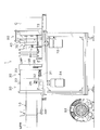
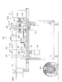
- (A) is a longitudinal sectional view showing one suction drive roller constituting the separation and delivery unit mounted on the same tack labeler, and (b) is the other suction drive roller constituting the same separation and delivery unit.
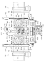
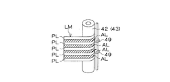
- (C) is a cross-sectional view showing a suction drive roller constituting the separation and delivery unit same as the above. It is explanatory drawing for demonstrating the auxiliary roller which comprises the separation delivery unit of a tack labeler same as the above. These are top views which show the state at the time of sticking in the separation delivery unit in the same tack labeler, a cutting
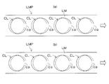
- (A) is the top view which looked at the substrate pair for label formation used for a tack labeler same as the above from one side
- (b) is the top view which looked at the substrate pair for label formation same as the above from the other surface is there. It is a perspective view which shows the state which has isolate
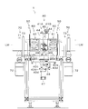
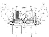
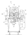
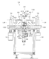
- FIG. 1 It is a front view which shows a tack labeler same as the above.
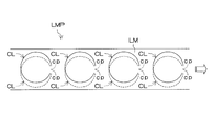
- A is the top view which looked at the base material pair for label formation in which the same notch was formed from one surface
- (b) is the top view which looked at the base material pair for label formation same as the above from the other surface.
- a long strip-shaped base material for label formation LM from which a tuck label having a predetermined shape is cut off can be peeled off on the sticking surface side.
- the label-forming base material pair LMP bonded together, and each label-forming base material LM has a tuck label-shaped cut CL having a connecting part cp partially connected to one end side in the longitudinal direction.
- the cut lines CL are sequentially formed at predetermined intervals in the direction, and the cut line CL formed on one label forming base material LM and the cut line CL formed on the other label forming base material LM do not coincide with each other.
- the label forming substrate pair LMP is fed out from the substrate pair roll MPR formed by winding the label forming substrate pair LMP which is displaced in the longitudinal direction of the label forming substrate LM in a roll shape.
- Label forming substrate LM After peeling, a tack label is formed by sequentially cutting the connecting portion cp in the cut line CL formed in each label forming base material LM, and the tack label is attached to the body portion of the cup-shaped container C.
- the labeler 1 is shown.
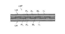
- the label-forming base material LM includes a base material layer BL formed of a plastic film or synthetic paper, and a display printing layer IL laminated on the outer surface of the base material layer BL. And an adhesive layer AL made of hot melt resin and a non-adhesive layer PL made of silicon resin laminated on the inner surface of the base material layer BL.
- the adhesive layer AL and the non-adhesive layer PL are composed of the base material layer BL. Are arranged alternately in the width direction.
- the label forming base material LM constituting the label forming base material pair LMP is in a state of being bonded to each other so that the adhesive layers AL of both label forming base materials LM do not contact each other.
- the non-adhesive layer PL is arranged in a state of being displaced in the width direction.
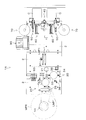
- the tack labeler 1 includes a roll holder 10 that rotatably holds a substrate pair roll MPR and a substrate pair roll MPR set on the roll holder 10 for label formation.
- a feeding unit 20 that feeds the base material pair LMP
- a base material pair storage unit 30 that stores the label forming base material pair LMP fed by the feeding unit 20, and a label forming base material pair from the base material pair storage unit 30
- a separation and delivery unit 40 that pulls out the LMP and separates and sends the LMP to each label forming substrate LM, and a connecting part cp in the cut CL formed in each label forming substrate LM sent by the separation and sending unit 40.
- a cutting unit 50 having a guillotine cutter that forms individual tack labels L by sequentially cutting, and each label shape
- the tack label L separated from the base material LM for use is attached to the container C that is transported to the sticking position, and each label forming base material LM from which the tack label has been cut is taken up and collected.
- the base material collecting unit 70 that performs the control, the main control unit (not shown) that comprehensively controls the operation of each unit, and the separation operation unit 40 that feeds the label forming base material pair LMP while cooperating with the main control unit
- a sub-control unit (not shown) for controlling the recording medium, and printed between the substrate pair storage unit 30 and the separation delivery unit 40 at a predetermined position corresponding to the tack label in the label forming substrate pair LMP.
- a mark sensor 81 for detecting a mark is installed.
- the feeding unit 20 rotates a feeding nip roller 21 that is erected on the base plate 2 and includes a driving roller 22 and a driven roller 23, and the driving roller 22 of the feeding nip roller 21.
- a guide roller 25 installed between the substrate pair roll MPR set on the roll holder 10 and the feeding nip roller 21, and the label forming substrate pair LMP is moved to the driving roller 22.
- the driving roller 22 is rotated by the geared motor 24 while being sandwiched by the driven roller 23, the label forming substrate pair LMP is fed out from the substrate pair roll MPR set in the roll holder 10. Yes.
- the base pair storage unit 30 is installed on the opposite side of the driven roller 23 with respect to the driving roller 22 of the feeding unit 20 and extends in the width direction of the base plate 2.
- a slider 32 that moves along the slide base 31, a dancer roller 33 that is rotatably provided on the slider 32, and biases the slider 32 toward one end of the slide base 31 (outside in the width direction of the base plate 2).
- the label forming substrate pair LMP fed by the feeding nip roller 21 is alternately wound around the driving roller 22, the dancer roller 33 and the guide roller 35.
- a roll detection sensor 36 comprising a transmissive photoelectric sensor for detecting the dancer roller 33 is installed in the middle of the movement range, and the label forming base material pair LMP is accumulated.
- the roll detection sensor 36 detects the dancer roller 33, but when the accumulated amount of the label forming substrate pair LMP decreases, that is, When the dancer roller 33 moves inward in the width direction of the base plate 2, the roll detection sensor 36 does not detect the dancer roller 33.
- the dancer roller 33 is not detected by the roll detection sensor 36, that is, while the accumulation amount of the label forming substrate pair LMP is insufficient, the feeding operation of the label forming substrate pair LMP by the feeding unit 20 is executed.
- the dancer roller 33 is detected by the roll detection sensor 36, that is, when the label forming substrate pair LMP is sufficiently accumulated, the feeding operation of the label forming substrate pair LMP by the feeding unit 20 is stopped.
- a control unit (not shown) performs ON / OFF control of the geared motor 24 of the feeding unit 20.
- the separation and delivery unit 40 includes a pair of suction drive rollers 41A and 41B installed in a state of penetrating the base plate 2 on both sides of the label-forming base material pair LMP.
- Servo motor 47 that rotates one suction drive roller 41A, and auxiliary rollers 49 and 49 that sandwich label forming base material LM between rotating suction drive rollers 41A and 41B, respectively, are provided.
- the two label forming bases are separated from the label forming base material pair LMP.
- the material LM is continuously separated.
- the one suction drive roller 41A is supported by a central shaft 42 penetrating the base plate 2 and rotatably supported by the central shaft 42 via a bearing.
- a roller cylinder 44 having a number of suction holes 44a, one end of which is open on the inner peripheral surface side and the other end thereof on the outer peripheral surface side, and the upper end of the central shaft 42 is located above the base plate 2.
- the support piece 40a On the side, it is fixed to the other end of the support piece 40a whose one end is supported on a support column erected on the base plate 2, and its lower end is on the lower side of the base plate 2 and both ends are connected to the base plate 2 via the support column. It is fixed to the attached flat bar 40c.
- the central shaft 42 includes a main suction path 42a whose upper end extending in the longitudinal direction at the center and a pair of suction drive rollers 41A and 41B on the outer peripheral surface. 44 and 44 are connected to the concave portion 42b formed in the portion extending from the position closest to the position 90 degrees in the delivery direction of the label forming base material LM, and the upper and lower five communication lines communicating the main suction path 42a and the concave portion 42b.
- a suction tube connecting elbow 42d for connection to the suction blower 82 is attached to the lower end of the main suction path 42a through a pressure regulating valve.
- the other suction drive roller 41B is also rotatably supported by a central shaft 43 passing through the base plate 2 and a bearing via a bearing.
- a roller cylinder 44 having a plurality of suction holes 44a, one end of which is open on the inner peripheral surface side and the other end thereof on the outer peripheral surface side.
- On the upper side it is rotatably supported on the other end of a support piece 40b whose one end is supported by a support column erected on the base plate 2, and its lower end rotates on a flat bar 40c on the lower side of the base plate 2. Supported as possible.
- the central shaft 43 is eccentric with respect to the lower shaft 43D rotatably supported by the flat bar 40c and the rotation center of the lower shaft 43D.
- the intermediate shaft 43M connected to the lower shaft 43D, the upper shaft 43U connected to the intermediate shaft 43M so that the rotation center coincides with the rotation center of the lower shaft 43D, and fixed to the upper shaft 43U
- a coil spring 46 having one end connected to the support member 40d attached to the lower shaft 43D and the other end connected to the support member 40e attached to the flat bar 40c.
- the roller cylinder 44 rotatably supported by the intermediate shaft 43M approaches and separates from the roller cylinder 44 of the one suction drive roller 41A, and by the coil spring 46 Intermediate shaft 43M (the roller pipe 44) is constantly biased in a direction toward the roller tube 44 of the one suction drive roller 41A. Accordingly, when setting the label forming base material pair LMP, the knob 45 is rotated so that the roller cylinder 44 of the one suction drive roller 41A is separated from the roller cylinder 44 of the other suction drive roller 41B.
- the roller cylinder 44 of the other suction drive roller 41B is returned to its original position by the urging force of the coil spring 46.
- the label-forming base material pair LMP is sandwiched between the roller cylinders 44 and 44 of the pair of suction drive rollers 41A and 41B.
- the central shaft 43 of the suction driving roller 41B also has a main suction path 43a whose upper end extending in the vertical direction is closed, and an intermediate shaft 43M.
- a recess 43b formed in a portion extending from a position where the roller cylinders 44, 44 of the pair of suction drive rollers 41A, 41B are closest to each other to a position of 90 degrees in the feeding direction of the label forming substrate LM on the outer peripheral surface of
- a suction elbow 43d is attached to the suction tube.
- each suction drive roller 41A, 41B includes a main body portion 44A formed of aluminum, a label-forming base material pair LMP and a label-forming base material pair LMP to be sandwiched and sent.
- the label forming substrate LM is formed of urethane rubber and covers the outer peripheral surface of the main body 44A so that the two label forming base materials LM separated from the main body 44A do not slip.
- Suction holes 44a are formed on both sides of 44B.
- the pair of suction drive rollers 41A and 41B are attached with gears 48A and 48B that rotate together with the respective roller cylinders 44 and 44 and mesh with each other, and the gear 48A of one suction drive roller 41A is By meshing with a gear attached to the drive shaft of the servo motor 47, the rotational drive force of the servo motor 47 is transmitted to the pair of suction drive rollers 41A and 41B, and the pair of suction drive rollers 41A and 41B are reversed. It is designed to rotate in the direction.
- the auxiliary roller 49 that contacts the sticking surface side of the label forming substrate LM is arranged in two upper and lower levels so that the height position can be adjusted. It is a disk shape smaller than the width of the non-adhesive layer PL of LM, and corresponds to the non-adhesive layer PL so as not to contact the adhesive layer AL on the sticking surface of the label forming substrate LM as shown in FIG. It is installed at a height. Therefore, the adhesive forming the adhesive layer AL does not adhere to the auxiliary roller 49, and the label forming substrate LM can be smoothly fed out.
- This separation / delivery unit 40 is so-called pitch-controlled, in which the label-forming substrate pair LMP is intermittently delivered by a predetermined amount by a sub-control unit linked with the main control unit.
- the mark sensor 81 detects the mark printed on the label forming substrate pair LMP so that the connecting portion formed on the label forming substrate LM comes to the cutting position of the cutting unit 50, a predetermined place
- the label-forming substrate pair LMP is sent out only in a fixed amount.
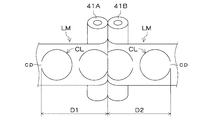
- the label-forming base material pair LMP includes a cut CL formed on one label-forming base material LM and a cut CL formed on the other label-forming base material LM. Since the label forming base material LM is displaced in the longitudinal direction so that the label forming base material LM is not aligned with the longitudinal direction, the separating and sending unit 40 sends out a predetermined amount while separating the label forming base materials LM bonded together. However, as shown in FIG.
- the distance D1 from the separation position of the label forming substrate LM to the stop position of the connecting portion cp in the cut CL of one label forming substrate LM, and the label forming substrate LM The distance D2 from the separation position to the stop position of the connecting portion cp in the cut CL of the other label-forming substrate LM is different. Accordingly, the cutting unit 50 that sequentially cuts the connecting portions cp in the cuts CL formed in the separated label forming base materials LM is also at the stop position of the connecting portions cp in the cuts CL of the respective label forming base materials LM. In addition, it is installed in a state in which the other is displaced relative to either one.
- the sticking unit 60 is slightly more than the tack label L, which holds and holds each label forming base material LM fed by a predetermined amount while being separated by the separation and delivery unit 40.
- a suction hole 62a and a comb-like suction groove 62b communicating with the suction hole 62a are formed on the suction holding surface.
- the portion 63 is formed with two suction holes 63a and 63a on the suction holding surface, and a suction groove 63b communicating with the two suction holes 63a and 63a so as to surround the circular movable portion 62. Yes.
- the suction plate 61 is installed between the suction drive rollers 41A and 41B of the separation / delivery unit 40 and the cutting units 50 and 50 in a state of being close to both of them, and separates the label forming substrate LM.
- the suction plate 61 installed on the cutting unit 50 side far from the position is formed wider than the suction plate 61 installed on the other cutting unit 50 side.
- the movable portion 62 of the suction plate 61 is disposed such that the outer edge of the movable plate 62 coincides with the edge of the fixed portion 63 on the cutting unit 50 side and the outer periphery of the movable portion 62.
- the connecting portion cp in the formed cut CL comes to the cutting position, the movable portion 62 is located inside the portion that becomes the tack label L surrounded by the cut CL formed in each label forming base material LM. It is like that.
- the suction holes 62a and 63a of the suction plate 61 are connected to a suction blower 82 via a vacuum valve (not shown) using air as a drive source, and a control unit (not shown) operates the air valve 83.
- a vacuum valve (not shown) using air as a drive source
- a control unit (not shown) operates the air valve 83.
- the vacuum valve is opened and closed by controlling the supply of driving air for the vacuum valve, and the suction operation by the suction plate 61 is intermittently performed as described below.
- the suction operation by the suction plate 61 is started, and the label forming base material LM is held by the suction plate 61.
- the movable portion 62 of the suction plate 61 is positioned inside the portion that becomes the tack label L surrounded by the cut CL formed in each label forming base material LM.
- the cutting unit 50 cuts the connecting portion cp in the cut CL formed in each label forming base material LM
- the tack label L is separated from each label forming base material LM, and the separated tack
- the label L is sucked and held only by the movable part 62 of the suction plate 61.
- the movable portion 62 that sucks and holds the tack label L moves forward, and the tack label L is attached to the body portion of the container C that is transported to the attaching position by the container transport unit.
- the suction operation by the suction plate 61 is stopped, and the suction plate 61 is retracted to the initial position.
- the base material recovery unit 70 winds the label forming base material LM from which the tack label L has been cut by the cutting unit 50, and is a winding supported by the base plate 2 via a bearing.
- the geared motor 72 is maintained at a constant torque. Constant torque control is performed using a cycle conversion inverter. Therefore, when the feeding of the label forming base material LM by the separating and feeding unit 40 is stopped, the take-up reel 71 does not rotate, but the label forming base material LM starts to be fed by the separating and feeding unit 40. Then, the take-up reel 71 rotates and the label forming base material LM from which the tack label L is cut is taken up.
- the start end portion of the label forming substrate pair LMP delivered from the feeding unit 20 is peeled off and along the outer peripheral surfaces of the suction drive rollers 41A and 41B of the separation delivery unit 40.
- the suction driving rollers 41A and 41B are rotated in a state where the labels are formed, the label forming base materials LM bonded to each other are separated.
- the connection part cp in the cut CL formed in each label forming base material LM is located on the downstream side in the sending direction of the label forming base material LM, the cut CL is triggered by the connection part cp.
- the part that becomes the tuck label enclosed in is also reliably separated.
- the separate tack label L is formed by cut
- the label forming substrate pair LMP is configured so that the cut CL formed in one label forming substrate LM and the cut CL formed in the other label forming substrate LM do not coincide with each other. Since the position is shifted in the longitudinal direction of the label-forming base material LM, as shown in FIG. 9, a portion that becomes a tack label surrounded by a cut CL formed in one of the label-forming base materials LM However, it is stuck and held on the outer side of the part that becomes the tack label surrounded by the cut line CL in the other label forming substrate LM. Therefore, the portion that becomes the tack label surrounded by the cut line CL in both label forming base materials LM does not become free, and the label forming base material pair LMP can be fed out and sent out smoothly and reliably.
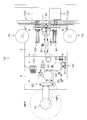
- FIGS. 13 to 15 show other embodiments. Since this tack labeler 1A also has basically the same configuration as the tack labeler 1 described above, the same components are denoted by the same reference numerals, description thereof is omitted, and different components will be described in detail.
- a label formation in which a tuck label-shaped cut CL having a connecting portion cp in which one end side in the longitudinal direction is partially connected to the label forming base material LM bonded in a peelable manner is formed in advance.
- a label-forming substrate pair in which a long strip-shaped label-forming substrate LM is detachably bonded on the sticking surface side is used.
- the tack labeler 1A forms a tack label-shaped cut CL on the label forming substrate LM forming the label forming substrate pair LMP1.
- the tack labeler 1A having a connecting part cp in which the downstream side in the sending direction is partially connected to the label forming base pair LMP1 between the base pair storage unit 30 and the separation delivery unit 40.
- a laser cutter 90 for forming a label-shaped cut CL is mounted.
- the label forming substrate LM on which the cut CL is formed by the laser cutter 90 is separated by the separation and delivery unit 40 immediately after the formation of the cut CL, so that it is formed on the label forming substrate pair LMP1.
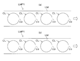
- the cut CL is the cut CL formed on one label forming substrate LM and the other label forming substrate LM like the label forming substrate pair LMP used in the tack labeler 1 described above. It is not necessary to shift the position CL in the longitudinal direction of the label forming substrate LM so that the cuts CL formed on each other do not coincide with each other, and the cuts CL formed on both label forming substrates LM match.
- the cut CL may be formed in the label-forming substrate pair LMP1 (see FIGS. 16A and 16B).
- the cut CL formed in one label forming base material LM and the cut CL formed in the other label forming base material LM are not displaced in the longitudinal direction of the label forming base material LM. Therefore, as shown in FIG. 17, the distance D1 from the separation position of the label forming substrate LM to the stop position of the connecting portion cp in the cut CL of one label forming substrate LM, and the label forming substrate LM The distance D2 from the separation position to the stop position of the connecting portion cp in the cut line CL of the other label forming substrate LM coincides.
- the pair of cutting units 50 are installed at positions separated by the same distance from the separation position of the label forming substrate LM, and the suction plates 61 of the pair of sticking units 60 are also the same.
- the width is set.
- the laser cutter 90 is used as the cut forming means for forming the cut CL in the label forming substrate pair LMP1, but the present invention is not limited to this, and the same cut is used.
- a cut CL may be formed in the label-forming substrate pair LMP1 by pressing the label-forming substrate pair LMP1 with a punching die having a shaped blade.
- the separation and delivery rollers such as the suction drive rollers 41A and 41B constituting the separation and delivery unit 40 are provided with a function as a cut forming means such as a die roll and an anvil roll, and the label forming substrate pair LMP1 is provided with two labels.
- the cut CL may be formed in the label forming substrate pair LMP1.
- this tack labeler 1B also has basically the same configuration as the tack labeler 1 described above, the same components are denoted by the same reference numerals, description thereof is omitted, and different components will be described in detail.
- a label formation in which a tuck label-shaped cut CL having a connecting portion cp in which one end side in the longitudinal direction is partially connected to the label forming base material LM bonded in a peelable manner is formed in advance.
- the individual tack label L is formed by using the base material pair LMP and the cutting unit 50 cuts the connecting portion cp.
- the long strip-shaped label forming base material is used.
- the individual tack labels L are formed by punching each label-forming substrate LM into a tack label shape at the position. Accordingly, in this tack labeler 1B, a punching unit 100 is installed in place of the cutting unit 50 of the tack labeler 1 described above.
- the punching unit 100 includes a punching die 101 having a tack label-shaped punching blade and a punching die 101 having a suction surface of the movable portion 62 of the fixed portion 63.
- a drive cylinder 102 that moves forward and backward with respect to the suction plate 61 on the front side of the suction plate 61 in a state in which the movable portion 62 is retracted so as to be flush with the suction surface, and the punching die 101 together with the drive cylinder 102
- Drive cylinder 103 that moves forward and backward between a forward position of 61 and a retracted position on the side, and in a state where drive cylinder 102 and punching die 101 are retracted to the side, movable portion 62 of suction plate 61 is It is possible to move forward and backward with the container C stopped forward.
- the label forming base material LM is sucked into the suction plate 61 by the punching die 101 as shown in FIGS. 22 (a) and 22 (b).
- the tack label L having a predetermined shape is punched out from the label forming substrate LM by being pressed onto the fixed portion 63, and the punched tack label L is sucked and held by the movable portion 62 of the suction plate 61. Subsequently, as shown in FIGS.
- the drive cylinder 102 and the punching die 101 are retracted to the side, and the movable portion 62 of the suction plate 61 holding the tack label L is advanced.
- the tack label L is stuck to the container C stopped at the front sticking position.
- the separation and delivery unit 40 includes the auxiliary rollers 49 and 49 that sandwich the label forming base material LM between the suction driving rollers 41A and 41B. Can be omitted.
- a nip roller composed of a driving roller and a driven roller having no suction function is provided at the position of the suction drive rollers 41A and 41B. It may be.
- the tack label-shaped cut CL has a connection part cp that is completely connected, but the connection part cp may be a perforation.
- the cut CL formed on one label forming substrate LM and the cut CL formed on the other label forming substrate LM do not coincide with each other.
- the position of the label-forming base material LM is shifted in the longitudinal direction, but the present invention is not limited to this.
Landscapes
- Making Paper Articles (AREA)
- Labeling Devices (AREA)
- Adhesive Tapes (AREA)
Priority Applications (4)
| Application Number | Priority Date | Filing Date | Title |
|---|---|---|---|
| PCT/JP2009/004306 WO2011027385A1 (ja) | 2009-09-01 | 2009-09-01 | ラベル形成用基材対及びタックラベラー |
| US13/389,542 US8986803B2 (en) | 2009-09-01 | 2009-09-01 | Label formation base material pair and tack labeler |
| EP09848917.2A EP2474584B1 (de) | 2009-09-01 | 2009-09-01 | Substratpaar zur etikettenerzeugung |
| JP2011529686A JP5525534B2 (ja) | 2009-09-01 | 2009-09-01 | ラベル形成用基材対 |
Applications Claiming Priority (1)
| Application Number | Priority Date | Filing Date | Title |
|---|---|---|---|
| PCT/JP2009/004306 WO2011027385A1 (ja) | 2009-09-01 | 2009-09-01 | ラベル形成用基材対及びタックラベラー |
Publications (1)
| Publication Number | Publication Date |
|---|---|
| WO2011027385A1 true WO2011027385A1 (ja) | 2011-03-10 |
Family
ID=43648949
Family Applications (1)
| Application Number | Title | Priority Date | Filing Date |
|---|---|---|---|
| PCT/JP2009/004306 Ceased WO2011027385A1 (ja) | 2009-09-01 | 2009-09-01 | ラベル形成用基材対及びタックラベラー |
Country Status (4)
| Country | Link |
|---|---|
| US (1) | US8986803B2 (de) |
| EP (1) | EP2474584B1 (de) |
| JP (1) | JP5525534B2 (de) |
| WO (1) | WO2011027385A1 (de) |
Cited By (2)
| Publication number | Priority date | Publication date | Assignee | Title |
|---|---|---|---|---|
| JP2022051210A (ja) * | 2020-09-18 | 2022-03-31 | 株式会社フジシール | フィルムオープナー |
| JP2024109345A (ja) * | 2023-02-01 | 2024-08-14 | プライムプラネットエナジー&ソリューションズ株式会社 | 巻回電極体の製造方法、該巻回電極体を備えた蓄電デバイスの製造方法、ならびに該巻回電極体の製造装置 |
Families Citing this family (9)
| Publication number | Priority date | Publication date | Assignee | Title |
|---|---|---|---|---|
| US8308363B2 (en) | 2006-05-23 | 2012-11-13 | Kraft Foods Global Brands Llc | Package integrity indicator for container closure |
| US8408792B2 (en) | 2007-03-30 | 2013-04-02 | Kraft Foods Global Brands Llc | Package integrity indicating closure |
| US20100018974A1 (en) | 2008-07-24 | 2010-01-28 | Deborah Lyzenga | Package integrity indicating closure |
| GB0819200D0 (en) | 2008-10-20 | 2008-11-26 | Cadbury Holdings Ltd | Packaging |
| US9656783B2 (en) | 2010-05-18 | 2017-05-23 | Intercontinental Great Brands Llc | Reclosable flexible packaging and methods for manufacturing same |
| PL2571766T3 (pl) | 2010-05-18 | 2015-02-27 | Intercontinental Great Brands Llc | Elastyczne opakowanie z możliwością wielokrotnego zamykania oraz sposoby jego wytwarzania |
| EP3109172B1 (de) | 2011-03-17 | 2018-08-15 | Intercontinental Great Brands LLC | Wiederverschliessbare flexible folienverpackungsprodukte und verfahren zur herstellung |
| DE102013020662B4 (de) * | 2013-12-06 | 2026-01-08 | Feintool International Holding Ag | Verfahren zur Herstellung von Lamellen für ein Lamellenpaket, insbesondere für elektrische Maschinen und Generatoren, Vorrichtung mit wenigstens einer Stanzpresse sowie nach dem Verfahren hergestellte Lamelle und Lamellenpaket |
| CN105366141B (zh) * | 2015-10-26 | 2018-03-02 | 京东方光科技有限公司 | 贴标装置 |
Citations (3)
| Publication number | Priority date | Publication date | Assignee | Title |
|---|---|---|---|---|
| JPH05117604A (ja) * | 1990-11-01 | 1993-05-14 | Koopack Kk | 粘着シールによる表示製品 |
| JPH10142742A (ja) * | 1996-11-07 | 1998-05-29 | Fuji Photo Film Co Ltd | 写真フイルムカートリッジ |
| WO2009110197A1 (ja) * | 2008-03-04 | 2009-09-11 | 株式会社フジシールインターナショナル | タックラベラー |
Family Cites Families (8)
| Publication number | Priority date | Publication date | Assignee | Title |
|---|---|---|---|---|
| US3312005A (en) * | 1962-10-04 | 1967-04-04 | Dennison Mfg Co | Linerless pressure-sensitive labels |
| US4335172A (en) * | 1977-03-28 | 1982-06-15 | Kabushiki Kaisha Sato | Pressure sensitive label strip |
| US4210688A (en) * | 1977-03-28 | 1980-07-01 | Kabushiki Kaisha Sato | Pressure sensitive label strip for use in a label printing machine |
| FI913739L (fi) * | 1991-05-09 | 1992-11-10 | Ko Pack Kk | Med limfoersegling foersett maerkningsmedel |
| EP1122174A3 (de) * | 1992-12-23 | 2001-09-12 | Greydon Wesley Nedblake, Jr. | System zur Herstellung von Etiketten von einem Band |
| US5707713A (en) * | 1996-02-21 | 1998-01-13 | Moore Business Forms, Inc. | Variable double sided linerless labels |
| US7625619B2 (en) * | 2000-09-29 | 2009-12-01 | Avery Dennison Corporation | Label sheet construction |
| US6596359B2 (en) * | 2001-02-02 | 2003-07-22 | Ncr Corporation | Duplex label laminate |
-
2009
- 2009-09-01 JP JP2011529686A patent/JP5525534B2/ja active Active
- 2009-09-01 US US13/389,542 patent/US8986803B2/en not_active Expired - Fee Related
- 2009-09-01 WO PCT/JP2009/004306 patent/WO2011027385A1/ja not_active Ceased
- 2009-09-01 EP EP09848917.2A patent/EP2474584B1/de not_active Not-in-force
Patent Citations (3)
| Publication number | Priority date | Publication date | Assignee | Title |
|---|---|---|---|---|
| JPH05117604A (ja) * | 1990-11-01 | 1993-05-14 | Koopack Kk | 粘着シールによる表示製品 |
| JPH10142742A (ja) * | 1996-11-07 | 1998-05-29 | Fuji Photo Film Co Ltd | 写真フイルムカートリッジ |
| WO2009110197A1 (ja) * | 2008-03-04 | 2009-09-11 | 株式会社フジシールインターナショナル | タックラベラー |
Cited By (4)
| Publication number | Priority date | Publication date | Assignee | Title |
|---|---|---|---|---|
| JP2022051210A (ja) * | 2020-09-18 | 2022-03-31 | 株式会社フジシール | フィルムオープナー |
| JP7593762B2 (ja) | 2020-09-18 | 2024-12-03 | 株式会社フジシール | フィルムオープナー |
| JP2024109345A (ja) * | 2023-02-01 | 2024-08-14 | プライムプラネットエナジー&ソリューションズ株式会社 | 巻回電極体の製造方法、該巻回電極体を備えた蓄電デバイスの製造方法、ならびに該巻回電極体の製造装置 |
| JP7778099B2 (ja) | 2023-02-01 | 2025-12-01 | プライムプラネットエナジー&ソリューションズ株式会社 | 巻回電極体の製造方法、該巻回電極体を備えた蓄電デバイスの製造方法、ならびに該巻回電極体の製造装置 |
Also Published As
| Publication number | Publication date |
|---|---|
| JPWO2011027385A1 (ja) | 2013-01-31 |
| US20120141715A1 (en) | 2012-06-07 |
| EP2474584A4 (de) | 2014-02-26 |
| US8986803B2 (en) | 2015-03-24 |
| JP5525534B2 (ja) | 2014-06-18 |
| EP2474584A1 (de) | 2012-07-11 |
| EP2474584B1 (de) | 2016-03-09 |
Similar Documents
| Publication | Publication Date | Title |
|---|---|---|
| JP5525534B2 (ja) | ラベル形成用基材対 | |
| US8544519B2 (en) | Tack labeler | |
| CN101616803B (zh) | 施加标签的设备和方法 | |
| WO2012014958A1 (ja) | ラベル後処理装置及びラベル処理装置 | |
| JP4274325B2 (ja) | テープ貼付装置 | |
| JP2005347618A (ja) | 感光性ウエブユニット、感光性積層体の製造装置及び製造方法 | |
| JP2009023301A (ja) | 積層体フイルムの貼り付け方法 | |
| CN103035558A (zh) | 薄片粘贴装置及粘贴方法、以及薄片制造装置及制造方法 | |
| WO2016166927A1 (ja) | シート供給装置およびシート供給方法 | |
| JP2007078978A (ja) | 枚葉体からのセパレータ剥離方法および積層光学フィルムの製造方法並びにこれらを用いた製造装置 | |
| CN111498536B (zh) | 把平张印刷品复合成卷筒不干胶机贴标签的装置及方法 | |
| JP5660859B2 (ja) | シート積層装置及び積層方法 | |
| JP6543152B2 (ja) | シート貼付装置および貼付方法並びに接着シート原反 | |
| JP2987143B1 (ja) | 粘着性シートの製造装置 | |
| JP2013193787A (ja) | シート貼付装置 | |
| JP5827524B2 (ja) | シート貼付装置及びシート貼付方法 | |
| JP4674145B2 (ja) | 接着ラベル及び接着ラベルロール | |
| JP5827525B2 (ja) | シート貼付装置及びシート貼付方法 | |
| JP2012188161A (ja) | シート貼付装置および貼付方法 | |
| JP2013203405A (ja) | ラベラー | |
| JP4657069B2 (ja) | 接着ラベル貼り付け装置及び方法 | |
| JP2776769B2 (ja) | 包装フィルムへの開封手段の付与方法及びその装置 | |
| JP7364327B2 (ja) | 不要シート除去装置および不要シート除去方法 | |
| JP3546876B2 (ja) | ラミネータ | |
| JP2014183095A (ja) | シート貼付装置及び貼付方法 |
Legal Events
| Date | Code | Title | Description |
|---|---|---|---|
| 121 | Ep: the epo has been informed by wipo that ep was designated in this application |
Ref document number: 09848917 Country of ref document: EP Kind code of ref document: A1 |
|
| WWE | Wipo information: entry into national phase |
Ref document number: 2011529686 Country of ref document: JP |
|
| WWE | Wipo information: entry into national phase |
Ref document number: 13389542 Country of ref document: US |
|
| NENP | Non-entry into the national phase |
Ref country code: DE |
|
| WWE | Wipo information: entry into national phase |
Ref document number: 2009848917 Country of ref document: EP |