WO2011027493A1 - カッティング装置およびそのカット方法 - Google Patents
カッティング装置およびそのカット方法 Download PDFInfo
- Publication number
- WO2011027493A1 WO2011027493A1 PCT/JP2010/003479 JP2010003479W WO2011027493A1 WO 2011027493 A1 WO2011027493 A1 WO 2011027493A1 JP 2010003479 W JP2010003479 W JP 2010003479W WO 2011027493 A1 WO2011027493 A1 WO 2011027493A1
- Authority
- WO
- WIPO (PCT)
- Prior art keywords
- image
- cutting
- mark
- reference mark
- printed
- Prior art date
- Legal status (The legal status is an assumption and is not a legal conclusion. Google has not performed a legal analysis and makes no representation as to the accuracy of the status listed.)
- Ceased
Links
Images



Classifications
-
- B—PERFORMING OPERATIONS; TRANSPORTING
- B41—PRINTING; LINING MACHINES; TYPEWRITERS; STAMPS
- B41J—TYPEWRITERS; SELECTIVE PRINTING MECHANISMS, i.e. MECHANISMS PRINTING OTHERWISE THAN FROM A FORME; CORRECTION OF TYPOGRAPHICAL ERRORS
- B41J11/00—Devices or arrangements of selective printing mechanisms, e.g. ink-jet printers or thermal printers, for supporting or handling copy material in sheet or web form
- B41J11/66—Applications of cutting devices
- B41J11/70—Applications of cutting devices cutting perpendicular to the direction of paper feed
- B41J11/706—Applications of cutting devices cutting perpendicular to the direction of paper feed using a cutting tool mounted on a reciprocating carrier
-
- B—PERFORMING OPERATIONS; TRANSPORTING
- B41—PRINTING; LINING MACHINES; TYPEWRITERS; STAMPS
- B41J—TYPEWRITERS; SELECTIVE PRINTING MECHANISMS, i.e. MECHANISMS PRINTING OTHERWISE THAN FROM A FORME; CORRECTION OF TYPOGRAPHICAL ERRORS
- B41J11/00—Devices or arrangements of selective printing mechanisms, e.g. ink-jet printers or thermal printers, for supporting or handling copy material in sheet or web form
- B41J11/66—Applications of cutting devices
- B41J11/68—Applications of cutting devices cutting parallel to the direction of paper feed
-
- B—PERFORMING OPERATIONS; TRANSPORTING
- B26—HAND CUTTING TOOLS; CUTTING; SEVERING
- B26D—CUTTING; DETAILS COMMON TO MACHINES FOR PERFORATING, PUNCHING, CUTTING-OUT, STAMPING-OUT OR SEVERING
- B26D1/00—Cutting through work characterised by the nature or movement of the cutting member or particular materials not otherwise provided for; Apparatus or machines therefor; Cutting members therefor
- B26D1/01—Cutting through work characterised by the nature or movement of the cutting member or particular materials not otherwise provided for; Apparatus or machines therefor; Cutting members therefor involving a cutting member which does not travel with the work
- B26D1/04—Cutting through work characterised by the nature or movement of the cutting member or particular materials not otherwise provided for; Apparatus or machines therefor; Cutting members therefor involving a cutting member which does not travel with the work having a linearly-movable cutting member
- B26D1/045—Cutting through work characterised by the nature or movement of the cutting member or particular materials not otherwise provided for; Apparatus or machines therefor; Cutting members therefor involving a cutting member which does not travel with the work having a linearly-movable cutting member for thin material, e.g. for sheets, strips or the like
-
- B—PERFORMING OPERATIONS; TRANSPORTING
- B26—HAND CUTTING TOOLS; CUTTING; SEVERING
- B26D—CUTTING; DETAILS COMMON TO MACHINES FOR PERFORATING, PUNCHING, CUTTING-OUT, STAMPING-OUT OR SEVERING
- B26D5/00—Arrangements for operating and controlling machines or devices for cutting, cutting-out, stamping-out, punching, perforating, or severing by means other than cutting
-
- B—PERFORMING OPERATIONS; TRANSPORTING
- B26—HAND CUTTING TOOLS; CUTTING; SEVERING
- B26D—CUTTING; DETAILS COMMON TO MACHINES FOR PERFORATING, PUNCHING, CUTTING-OUT, STAMPING-OUT OR SEVERING
- B26D5/00—Arrangements for operating and controlling machines or devices for cutting, cutting-out, stamping-out, punching, perforating, or severing by means other than cutting
- B26D5/20—Arrangements for operating and controlling machines or devices for cutting, cutting-out, stamping-out, punching, perforating, or severing by means other than cutting with interrelated action between the cutting member and work feed
- B26D5/30—Arrangements for operating and controlling machines or devices for cutting, cutting-out, stamping-out, punching, perforating, or severing by means other than cutting with interrelated action between the cutting member and work feed having the cutting member controlled by scanning a record carrier
-
- B—PERFORMING OPERATIONS; TRANSPORTING
- B26—HAND CUTTING TOOLS; CUTTING; SEVERING
- B26D—CUTTING; DETAILS COMMON TO MACHINES FOR PERFORATING, PUNCHING, CUTTING-OUT, STAMPING-OUT OR SEVERING
- B26D5/00—Arrangements for operating and controlling machines or devices for cutting, cutting-out, stamping-out, punching, perforating, or severing by means other than cutting
- B26D5/20—Arrangements for operating and controlling machines or devices for cutting, cutting-out, stamping-out, punching, perforating, or severing by means other than cutting with interrelated action between the cutting member and work feed
- B26D5/30—Arrangements for operating and controlling machines or devices for cutting, cutting-out, stamping-out, punching, perforating, or severing by means other than cutting with interrelated action between the cutting member and work feed having the cutting member controlled by scanning a record carrier
- B26D5/34—Arrangements for operating and controlling machines or devices for cutting, cutting-out, stamping-out, punching, perforating, or severing by means other than cutting with interrelated action between the cutting member and work feed having the cutting member controlled by scanning a record carrier scanning being effected by a photosensitive device
-
- B—PERFORMING OPERATIONS; TRANSPORTING
- B41—PRINTING; LINING MACHINES; TYPEWRITERS; STAMPS
- B41J—TYPEWRITERS; SELECTIVE PRINTING MECHANISMS, i.e. MECHANISMS PRINTING OTHERWISE THAN FROM A FORME; CORRECTION OF TYPOGRAPHICAL ERRORS
- B41J11/00—Devices or arrangements of selective printing mechanisms, e.g. ink-jet printers or thermal printers, for supporting or handling copy material in sheet or web form
- B41J11/66—Applications of cutting devices
- B41J11/663—Controlling cutting, cutting resulting in special shapes of the cutting line, e.g. controlling cutting positions, e.g. for cutting in the immediate vicinity of a printed image
-
- B—PERFORMING OPERATIONS; TRANSPORTING
- B26—HAND CUTTING TOOLS; CUTTING; SEVERING
- B26D—CUTTING; DETAILS COMMON TO MACHINES FOR PERFORATING, PUNCHING, CUTTING-OUT, STAMPING-OUT OR SEVERING
- B26D5/00—Arrangements for operating and controlling machines or devices for cutting, cutting-out, stamping-out, punching, perforating, or severing by means other than cutting
- B26D5/20—Arrangements for operating and controlling machines or devices for cutting, cutting-out, stamping-out, punching, perforating, or severing by means other than cutting with interrelated action between the cutting member and work feed
- B26D5/30—Arrangements for operating and controlling machines or devices for cutting, cutting-out, stamping-out, punching, perforating, or severing by means other than cutting with interrelated action between the cutting member and work feed having the cutting member controlled by scanning a record carrier
- B26D5/32—Arrangements for operating and controlling machines or devices for cutting, cutting-out, stamping-out, punching, perforating, or severing by means other than cutting with interrelated action between the cutting member and work feed having the cutting member controlled by scanning a record carrier with the record carrier formed by the work itself
-
- B—PERFORMING OPERATIONS; TRANSPORTING
- B26—HAND CUTTING TOOLS; CUTTING; SEVERING
- B26F—PERFORATING; PUNCHING; CUTTING-OUT; STAMPING-OUT; SEVERING BY MEANS OTHER THAN CUTTING
- B26F1/00—Perforating; Punching; Cutting-out; Stamping-out; Apparatus therefor
- B26F1/38—Cutting-out; Stamping-out
- B26F1/3806—Cutting-out; Stamping-out wherein relative movements of tool head and work during cutting have a component tangential to the work surface
Definitions
- the present invention relates to a cutting apparatus provided with a cutting head for performing a cutting process on a target medium, and a cutting method using the cutting apparatus.
- the target medium is obtained by combining the operation of reciprocating the cutting head left and right with respect to the target medium supported by the platen and the operation of feeding the target medium back and forth. It is known that the material is cut.
- a printer apparatus configured to print an image on the surface of a target medium using a printer head that ejects ink from ejection nozzles instead of the cutting head.
- FIG. 1 of Patent Document 1 discloses a configuration in which a carriage 22 on which an inkjet head 26 is mounted and a carriage 24 on which a cutting head 28 is mounted are movable along the guide rail 18. ing. With this configuration, printing and cutting can be performed on the sheet 100 placed on the base member 12.
- an image and, for example, four reference marks are printed so as to surround the image using a printer head. Then, when performing the cutting process using the cutting head, the printing position of the image with respect to the register mark can be grasped by detecting the position of these register marks, and the cutting process can be performed at a position corresponding to the image. ing.
- printing and cutting are performed on a sheet-like target medium, for example, while printing the target medium forward, printing is performed on the entire print area of the target medium, and the roll is wound up.
- the target medium wound up in a roll shape is once back-feeded, and the first printed portion of the target medium (print start position) On the platen.
- the position of the first reference mark is detected by the registration mark detection unit, and the target medium is fed back and forth to detect the position of the second reference mark.
- the registration mark detection unit is moved left and right to detect the position of the third reference mark, and the target medium is sent back and forth again to detect the position of the fourth reference mark.
- the positional deviation at the time of detecting the position of the reference mark is less likely to occur, but the target medium is temporarily removed before starting the cutting process. Since it is back-fed and sent backward, there has been a problem that misalignment tends to occur at this time.
- the present invention has been made in view of the above problems, and an object of the present invention is to provide a cutting apparatus capable of performing a cutting process in a state in which the positional accuracy between the cutting head and the target medium is ensured, and a cutting method thereof.
- the cutting apparatus scans in opposition to medium support means (for example, the platen 30 in the embodiment) that supports a target medium (for example, the sheet material 8 in the embodiment).
- medium support means for example, the platen 30 in the embodiment
- a target medium for example, the sheet material 8 in the embodiment.
- a guide rail that extends in the direction, and a guide rail that is movably provided along the guide rail, and ejects ink toward a target medium supported by the medium support means, and serves as a reference around the image and the periphery of the image.
- a printer head that prints marks (for example, register marks T1, T2, T3, and T4 in the embodiment) and a target medium that is movably provided along the guide rail and supported by the medium support means.
- a cutting head that performs processing (for example, the cutter blade 53 in the embodiment), and a target medium in a conveyance direction orthogonal to the scanning direction
- a mark position detection unit for example, a registration mark detection unit 54 in the embodiment
- the mark position detection unit A cut position setting unit (for example, an embodiment) that detects a print position of the image with respect to the reference mark based on the obtained position of the reference mark and sets a cut processing position corresponding to the print position of the image Controller 9), printing the image and the reference mark while feeding the target medium to one side in the transport direction by the medium feeding mechanism, and cutting it at the cutting position set in the cutting position setting section It is configured to process, and before starting the cutting process, the transport direction of the plurality of images The position of the reference mark printed around the other side image (for example, the image N1 in the embodiment) printed on the most other side is detected, and the other side image is cut. Yes.
- At least three reference marks are printed around the image by the printer head, and printed around the other image by the mark position detection unit before starting the cutting process. It is preferable to detect the positions of at least three reference marks.
- the first reference mark for example, the closest to the mark position detection unit among the reference marks printed around the image
- the mark position detection unit is moved in the scanning direction to be printed in the scanning direction with respect to the first reference mark.
- the position of a second fiducial mark for example, the register mark T2 in the embodiment
- the target medium is fed in the carrying direction by the medium feeding mechanism and printed in the carrying direction with respect to the second fiducial mark. It is preferable to detect the position of the image by detecting the position of the third reference mark (for example, the register mark T3 in the embodiment).
- the cutting method according to the present invention prints an image and a reference mark around the image while feeding the target medium to one side in the transport direction, and determines the print position of the image with respect to the reference mark based on the position of the reference mark.
- a cutting method of a cutting apparatus that detects and sets a position for cutting with a cutting head to perform cutting, and before starting the cutting, the other of the plurality of images in the transport direction
- the cutting apparatus is configured to print the image and the reference mark while feeding the target medium to one side in the conveyance direction and then start cutting processing around the other side image printed on the other side in the conveyance direction.
- the position of the reference mark printed on is detected, and the other image is cut.
- the cutting apparatus it is preferable that at least three reference marks are printed around the image by the printer head, and the cutting position is set based on these positions.
- the cutting position is set based on these positions.
- the position of the first reference mark located closest to the mark position detection unit among the plurality of reference marks is detected, and the position of the second reference mark is detected by moving the mark position detection unit in the scanning direction.
- a configuration in which the target medium is fed in the transport direction by the medium feeding mechanism and the position of the third reference mark is detected to detect the print position of the image is preferable.
- the position of the three reference marks can be detected and the position of the image with respect to the reference mark can be detected by moving the target medium only once in the transport direction.
- the position of the image can be detected by only one feed. It becomes. Therefore, by reducing the frequency with which the target medium is sent in the transport direction, it is possible to reduce the occurrence of positional deviation with respect to the target medium and to ensure the positional accuracy between the cutting head and the target medium.
- the cutting method according to the present invention includes a first step of detecting a position of a reference mark printed around the other side image of the plurality of images before starting the cutting process, and the other side image. And a second step of performing a cutting process.
- the print position of the image with respect to the reference mark can be detected from this configuration by sending the target medium only once in the transport direction. Therefore, it is possible to ensure the positional accuracy between the cutting head and the target medium by reducing the frequency with which the target medium is sent in the transport direction and reducing the occurrence of positional deviation with respect to the target medium.
- FIGS. 1 is a perspective view of the cutting device 1
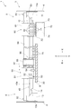
- FIG. 2 is an internal structure of a main body 3 described later
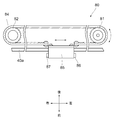
- FIG. 3 is a plan view of a unit driving device 80 described later
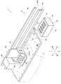
- FIG. 4 is a perspective view around a printing unit 60 described later.
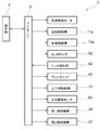
- FIG. 5 shows a control system diagram of the cutting apparatus 1.
- the cutting device 1 is mainly configured by a support portion 2 including a pair of left and right support legs 2a and 2a and a main body portion 3 supported by the support portion 2 and extending left and right.
- a left main body portion 5 and a right main body portion 6 are formed on the left and right ends of the main body portion 3, respectively, and these outer peripheral portions are covered with a main body cover 4.
- a controller 9 to which an operation signal from the operation unit 7 is input is provided inside the left main body unit 5.
- the controller 9 is electrically connected to each constituent member to be described later, and an operation signal is output to these to perform operation control. Specifically, as shown in FIG. 5, driving of a longitudinal drive motor, which will be described later, driving of the left swing mechanism 11 a, driving of the right swing mechanism 13 a, vertical movement of the cutter holder 52, and printer head 62 (discharge nozzle) Ink discharge, driving of the vertical movement mechanism 74, driving of the left and right drive motor 83, connection by the first connection mechanism 86, and connection by the second connection mechanism 87 are controlled. In addition, the controller 9 receives the inspection light reception result in the register mark detection unit 54 described later.
- a medium feeding mechanism 20 Between the left main body 5 and the right main body 6, a medium feeding mechanism 20, a flat platen 30 that supports the sheet material 8 that is the object of printing and cutting, and an upper portion of the platen 30 extend left and right.
- the medium feeding mechanism 20 is arranged on the lower part of the guide member 40 so as to be lined up on the left and right, and is rotatable on the plurality of pinch rollers 15, and exposed to the platen 30 below the pinch rollers 15.
- the feed roller 16 provided as described above is mainly configured.
- the feed roller 16 is rotated by a front / rear drive motor (not shown). With this configuration, the sheet material 8 can be fed back and forth by a predetermined distance by rotating the feed roller 16 with the front and rear drive motor while the sheet material 8 is sandwiched between the feed roller 16 and the pinch roller 15. .
- the cutting unit 50 is mainly composed of a cutting carriage 51, a cutter holder 52, and a registration mark detector 54.
- the cutting carriage 51 is attached to a guide rail 40 a formed on the front surface side of the guide member 40 so as to be movable in the left and right directions, and serves as an attachment base for the cutter holder 52 and the registration mark detection unit 54. Further, on the right surface of the cutting carriage 51, an engaging portion (not shown) that can be engaged with a right hook 14 described later is formed.
- the cutter holder 52 is mounted to be movable up and down with respect to the cutting carriage 51, and a cutter blade 53 is detachably attached to the lower end portion of the cutter holder 52.
- the registration mark detection unit 54 includes a light emitting unit (not shown) and a light receiving unit (not shown) on its lower surface. The reflected light of the inspection light emitted downward from the light emitting unit is received by the light receiving unit. For example, on the surface of the sheet material 8 that has not been printed, the inspection light (intensity inspection light) is reflected and received by the light receiving unit, while the registration marks T1 to T4 (described later) are printed. The light receiving sensitivity of the light receiving unit is set so that the inspection light is not reflected (low intensity inspection light is reflected).
- the printing unit 60 is mainly composed of a print carriage 61 and a plurality of printer heads 62. Similar to the cutting carriage 51, the print carriage 61 is attached to the guide rail 40a so as to be movable left and right, and serves as an attachment base for the printer head 62. Further, an engagement portion 61a that can be engaged with a left hook 12 described later is formed on the left surface of the print carriage 61 (see FIG. 4).
- the plurality of printer heads 62 are composed of, for example, magenta, yellow, cyan, and black. A plurality of ejection nozzles (not shown) that eject ink downward are formed on the lower surface of each printer head 62.
- a maintenance device 70 is provided inside the left main body 5.
- the maintenance device 70 is provided in (four) suction caps 71 formed according to the shape of the lower surface of the printer head 62, a stage 72 on which the suction cap 71 is mounted, a device main body 73, and the device main body 73.
- the vertical movement mechanism 74 is mainly configured. With this configuration, the stage 72 can be moved up by the vertical movement mechanism 74 with the printer head 62 and the suction cap 71 facing each other vertically so that the lower surface of the printer head 62 can be covered with the suction cap 71. It has become. By covering the lower surface of the printer head 62 in this way, it is possible to prevent ink drying (thickening) at the ejection nozzle.
- the unit driving device 80 includes a driving pulley 81 and a driven pulley 82 that are provided at the left and right ends of the guide member 40, and a left and right driving motor 83 that rotationally drives the driving pulley 81.
- the belt-shaped toothed drive belt 84 wound around the pulleys 81 and 82 and the drive carriage 85 connected to the toothed drive belt 84 are mainly configured.
- a first coupling mechanism 86 is formed on the left side of the drive carriage 85 to detachably connect the print carriage 61 and the drive carriage 85.
- a second connection mechanism 87 configured similarly to the first connection mechanism 86 and detachably connecting the cutting carriage 51 and the drive carriage 85 is formed.
- the said 1st connection mechanism 86 and the 2nd connection mechanism 87 it is possible to use the structure etc. which make an engagement protrusion engage and connect, for example, a structure using magnetism, etc. is there.
- the controller 9 performs drive control of the left and right drive motor 83, the first coupling mechanism 86, and the second coupling mechanism 87, so that the cutting unit 50 or the printing unit 60 is coupled to the driving carriage 85. Control to move left and right along the guide rail 40a can be performed.
- a left hook support portion 11 in which a left swing mechanism 11 a is incorporated is fixed inside the left main body portion 5.
- the left swing mechanism 11a can swing the left hook 12 up and down to engage or disengage the engagement portion 61a of the print carriage 61 and the left hook 12.
- a right hook support portion 13 in which a right swing mechanism 13 a is incorporated is fixed inside the right main body portion 6. Similar to the left hook support portion 11, the right hook 14 is swung up and down by the right swing mechanism 13 a to engage or disengage the engaging portion of the cutting carriage 51 and the right hook 14. Can be made.
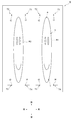
- FIG. 6 is a plan view of the printed sheet material 8
- FIG. 7 is a flowchart of the cutting apparatus 1.
- the cutting apparatus 1 can perform only printing or only cut processing on the sheet material 8, for example, in addition to continuously performing printing and cutting processing. is there.
- the drive carriage 85 is not connected to either the cutting unit 50 or the printing unit 60 before the start of printing (standby state).
- the engaging portion of the cutting carriage 51 and the right hook 14 are engaged, and the cutting unit 50 is held at the right end of the guide rail 40a, while the engaging portion 61a of the printing carriage 61 and the left hook 12 are held.
- the printing unit 60 is held at the left end of the guide rail 40a.
- the suction cap 71 covers the lower surface of the printer head 62.
- step S101 shown in FIG. 7 when printing is started by the operator operating the operation unit 7, the drive carriage 85 is moved to the left based on the operation signal from the controller 9. The drive carriage 85 and the print carriage 61 are connected. Then, the suction cap 71 is moved downward, and the engagement between the engaging portion 61a and the left hook 12 is released, so that the printing unit 60 is movable along the guide rail 40a.
- FIG. 6 An example of the sheet material 8 printed in this way is shown in FIG. 6, and the sheet material 8 is printed in order from the front side.
- FIG. 6 together with a plurality of images A1, A2, B1, B2,..., N1, N2, there are four L-shaped registration marks T1 to T4 printed so as to surround each image. Are printed. For each image, a registration mark T1 is printed on the left rear side, T2 is printed on the right rear side, T3 is printed on the right front side, and T4 is printed on the left front side.
- step S102 the printing unit 60 is moved to the left and held at the left end of the guide rail 40a, and the connection between the drive carriage 85 and the printing carriage 61 by the first connecting mechanism 86 is released. . Then, after the drive carriage 85 is moved to the right and the drive carriage 85 and the cutting carriage 51 are connected by the second connecting mechanism 87, the engagement between the engaging portion of the cutting carriage 51 and the right hook 14 is released, The cutting unit 50 is moved along the guide rail 40a.
- step S103 the process proceeds to step S103, and the positions of the register marks T1 to T4 corresponding to the image N1 are detected.
- the sheet material 8 remains in the front-rear position when printing is completed, that is, the vicinity of the portion where the images N1 and N2 are printed is placed on the platen 30. Therefore, the registration mark detection unit 54 can be positioned above the registration mark T1 automatically printed in correspondence with the image N1 only by moving the cutting unit 50 connected to the drive carriage 85 to the left, which will be described later.
- the registration mark position can be sequentially detected. Therefore, there is no need to newly set a position for starting the cutting process, and the starting position for the cutting process can be automatically set, so that the control configuration can be configured simply.
- the left and right line h1 of the registration mark T1 passes below the registration mark detection unit 54 by moving the sheet material 8 back and forth.
- the front and rear positions of the left and right lines h1 can be detected from the result of the inspection light received by the light receiving unit.
- the front / rear line v1 of the registration mark T1 passes below the registration mark detection unit 54 by moving the cutting unit 50 to the left / right with the front / rear position of the sheet material 8 fixed.
- the left and right positions of the front and rear line v1 can be detected.
- the first reference position t1 where the left / right line h1 and the front / rear line v1 intersect can be calculated from the front / rear position and the left / right position detected as described above.
- the cutting unit 50 is moved to the right to be positioned near the register mark T2.
- the second reference position t2 where the left and right lines of the register mark T2 intersect with the front and rear lines is calculated.
- the sheet material 8 is fed backward to calculate the third reference position t3 of the position registration mark T3, and then the cutting unit 50 is moved leftward to calculate the fourth reference position t4 of the registration mark T4.
- the controller 9 calculates the printing position of the image N1 with respect to the first reference position t1 to fourth reference position t4. Then, cutting position data indicating where the sheet material 8 is to be cut is set. It should be noted that, based on the printing position data used at the time of printing, the cutting position data is set in advance, and the cutting position data is corrected and set according to the calculated printing position of the image N1. May be. With this configuration, even when the shape of the image N1 is slightly deformed as the ink is dried, the cutting process can be performed at a position corresponding to the deformed shape. It becomes possible. For example, even when the rear part of the image N1 is deformed so as to spread with respect to the front part (deformed into a trapezoidal shape), the keystone correction for matching the cut position with the image N1 can be performed.
- step S104 based on the set cutting position data, the cutting unit 50 is moved left and right, and the sheet material 8 is fed back and forth while the cutter blade 53 is bitten into the sheet material 8 to thereby draw the contour of the image N1. Cut along.
- the cutting apparatus 1 has a configuration in which after the printing is completed, the sheet material 8 is cut back from the image N1 printed at the rear end without back-feeding the sheet material 8 backward as in the related art. ing. Therefore, by reducing the feeding amount of the sheet material 8 in the front-rear direction and the frequency of feeding the sheet material 8, the positional deviation of the sheet material 8 that easily occurs during feeding is reduced, and the sheet material 8 and the cutter blade 53 Position accuracy can be ensured. Conventionally, a large displacement occurs when backfeeding backward, and this causes a detection error in which a registration mark cannot be detected because the registration mark is not positioned below the registration mark detection unit 54, and a series of operations is interrupted. There was a thing. On the other hand, in the cutting apparatus 1 according to the present invention, since the occurrence of misalignment can be reduced as described above, a series of operations can be executed efficiently without causing such a detection error.
- the cutting apparatus 1 is configured to perform cutting in order from the image printed at the rear end (last), the work time required for the back feed can be shortened, and printing and cutting processing can be performed. It is possible to improve the work efficiency by shortening the time required for a series of work.
- step S105 the process proceeds to step S105, and after the cutting process on the image N1 is completed, the cutting unit 50 is moved to the right, and in the same manner as the image N1, the first reference positions t1 to t4 of the registration marks T1 to T4 corresponding to the image N2. 4 Reference position t4 is calculated. Cut position data is set based on the calculated first reference position t1 to fourth reference position t4, and cut processing is performed along the contour of the image N2.
- step S106 the image A1 printed on the front end is cut, and then the process proceeds to step S107, where the image A2 printed on the right side of the image A1 is cut. finish.
- FIG. 8 is a plan view of the sheet material 8 on which images R1 and R2 having shapes different from those in FIG. 6 are printed side by side. As can be seen from FIG. 8, the images R1 and R2 have a shape that is longer in the front-rear direction than the image A1 and the like.
- the operation of the cutting apparatus 1 when the printer head 62 performs the cutting process on the sheet material 8 on which the images R1 and R2 as shown in FIG. 8 are printed will be described.
- the position of the cutting unit 50 when the cutting process on the image P1 is finished is, for example, the completion position a or the completion position b
- the first reference of the registration mark T1 corresponding to the image P2 closest to these completion positions is first detected.
- the second reference position t2, the third reference position t3, and the fourth reference position t4 are detected in this order, and the image P2 is cut.
- the fourth reference position t4 of the registration mark T4 corresponding to the image P2 closest to the completion position c is first detected.
- the third reference position t3, the second reference position t2, and the first reference position t1 are detected in this order, and the image P2 is cut.
- the position closest to the completion position among the plurality of registration marks corresponding to the adjacent images according to the completion position where the cutting process has been completed (the position where the feed amount of the sheet material 8 forward and backward can be reduced).
- Position detection is performed in order from the registration mark. By doing so, the feed amount of the sheet material 8 in the front-rear direction can be reduced, the positional deviation of the sheet material 8 can be reduced, and the positional accuracy of the sheet material 8 and the cutter blade 53 can be maintained.
- the case where the present invention is applied to the cutting apparatus 1 that includes the printer head 62 and can perform printing is exemplified.
- the cutting that does not include the printer head 62 and can only perform the cutting process is also applicable to the device.
- the configuration in which the four L-shaped registration marks T1 to T4 are printed for one image has been described as an example, but the present invention is not limited to this configuration.
- three registration marks may be printed for one image, and the shape of the registration marks is not limited to an L shape.
- a configuration has been described in which four registration marks T1 to T4 are printed for one image, and the positions of the registration marks T1 to T4 are detected to calculate the print positions of the images. It is not limited to this configuration.
- a configuration is possible in which the position of an arbitrary detected first registration mark among the four registration marks T1 to T4 is set as the origin.
- a method of detecting a second registration mark that is printed in the left-right direction with respect to the detected first registration mark, and performing correction in the left-right direction and inclination correction, or for the detected first registration mark It is also possible to detect the second registration marks printed in the front-rear direction and perform front-rear direction correction and tilt correction. Further, by detecting a second registration mark printed diagonally with respect to the detected first registration mark, or by detecting the first to third registration marks, correction in the horizontal direction, correction in the front-rear direction, and A method of performing tilt correction is also possible.
- A1 image N1 image (the other image) T1-T4 Dragonfly (reference mark) 1 Cutting device 8 Sheet material (target medium) 9 Controller (Cut position setting part) 20 Medium feed mechanism 30 Platen (medium support means) 40a Guide rail 51 Cutting carriage 53 Cutter blade (cutting head) 54 Registration Mark Detection Unit (Mark Position Detection Unit) 62 Printer head
Landscapes
- Life Sciences & Earth Sciences (AREA)
- Forests & Forestry (AREA)
- Engineering & Computer Science (AREA)
- Mechanical Engineering (AREA)
- Handling Of Sheets (AREA)
- Control Of Cutting Processes (AREA)
Abstract
Description
N1 画像(他方側画像)
T1~T4 トンボ(基準マーク)
1 カッティング装置
8 シート材(対象媒体)
9 コントローラ(カット位置設定部)
20 媒体送り機構
30 プラテン(媒体支持手段)
40a ガイドレール
51 カッティングキャリッジ
53 カッタ刃(カッティングヘッド)
54 トンボ検出部(マーク位置検出部)
62 プリンタヘッド
Claims (4)
- 対象媒体を支持する媒体支持手段と対向して走査方向に延びて設けられたガイドレールと、
前記ガイドレールに沿って移動自在に設けられて、前記媒体支持手段に支持された対象媒体に向けてインクを吐出して画像および前記画像の周囲に基準マークを印刷するプリンタヘッドと、
前記ガイドレールに沿って移動自在に設けられて、前記媒体支持手段に支持された対象媒体に対してカット加工を施すカッティングヘッドと、
前記走査方向に対して直交する搬送方向に対象媒体を送る媒体送り機構と、
前記ガイドレールに沿って移動自在に設けられて、前記基準マークの位置を検出するマーク位置検出部と、
前記マーク位置検出部において得られた前記基準マークの位置を基に、前記基準マークに対する前記画像の印刷位置を検出するとともに、前記画像の印刷位置に対応させてカット加工位置を設定するカット位置設定部とを有し、
前記媒体送り機構により対象媒体を前記搬送方向における一方側に送りながら前記画像および前記基準マークを印刷し、前記カット位置設定部において設定されたカット加工位置にカット加工を施すカッティング装置において、
カット加工を開始する前に複数の前記画像のうちの前記搬送方向における最も他方側に印刷された他方側画像の周囲に印刷された前記基準マークの位置を検出し、前記他方側画像に対してカット加工を施すことを特徴とするカッティング装置。 - 前記プリンタヘッドにより、前記画像の周囲に少なくとも3つの前記基準マークが印刷され、
カット加工を開始する前に、前記マーク位置検出部により、前記他方側画像の周囲に印刷された少なくとも3つの前記基準マークの位置を検出することを特徴とする請求項1に記載のカッティング装置。 - 前記画像に対するカット加工を開始する前に、
前記画像の周囲に印刷された前記基準マークのうち前記マーク位置検出部に対して最も近くに位置した第1基準マークの位置を前記マーク位置検出部により検出し、前記マーク位置検出部を前記走査方向に移動させて前記第1基準マークに対して前記走査方向に位置して印刷された第2基準マークの位置を検出し、前記媒体送り機構により前記対象媒体を前記搬送方向に送り前記第2基準マークに対して前記搬送方向に位置して印刷された第3基準マークの位置を検出して、前記画像の印刷位置を検出することを特徴とする請求項1または2に記載のカッティング装置。 - 対象媒体を搬送方向における一方側に送りながら画像および前記画像の周囲に基準マークを印刷し、前記基準マークの位置を基に前記基準マークに対する前記画像の印刷位置を検出して、カッティングヘッドによりカット加工を施す位置を設定してカット加工を施すカッティング装置のカット方法であって、
カット加工を開始する前に、複数の前記画像のうちの前記搬送方向における最も他方側に印刷された他方側画像の周囲に印刷された前記基準マークの位置を検出する第1のステップと、
前記他方側画像に対してカット加工を施す第2のステップとを有することを特徴とするカット方法。
Priority Applications (4)
| Application Number | Priority Date | Filing Date | Title |
|---|---|---|---|
| CN201080037823.1A CN102481793B (zh) | 2009-09-01 | 2010-05-25 | 切割装置及其切割方法 |
| EP10813448.7A EP2474422B1 (en) | 2009-09-01 | 2010-05-25 | Cutting device and cutting method thereof |
| KR1020127004892A KR101344431B1 (ko) | 2009-09-01 | 2010-05-25 | 커팅 장치 및 그 커트 방법 |
| US13/391,819 US8870363B2 (en) | 2009-09-01 | 2010-05-25 | Cutting device and cutting method thereof |
Applications Claiming Priority (2)
| Application Number | Priority Date | Filing Date | Title |
|---|---|---|---|
| JP2009201303A JP5336980B2 (ja) | 2009-09-01 | 2009-09-01 | カッティング装置およびそのカット方法 |
| JP2009-201303 | 2009-09-01 |
Publications (1)
| Publication Number | Publication Date |
|---|---|
| WO2011027493A1 true WO2011027493A1 (ja) | 2011-03-10 |
Family
ID=43649053
Family Applications (1)
| Application Number | Title | Priority Date | Filing Date |
|---|---|---|---|
| PCT/JP2010/003479 Ceased WO2011027493A1 (ja) | 2009-09-01 | 2010-05-25 | カッティング装置およびそのカット方法 |
Country Status (6)
| Country | Link |
|---|---|
| US (1) | US8870363B2 (ja) |
| EP (1) | EP2474422B1 (ja) |
| JP (1) | JP5336980B2 (ja) |
| KR (1) | KR101344431B1 (ja) |
| CN (1) | CN102481793B (ja) |
| WO (1) | WO2011027493A1 (ja) |
Families Citing this family (35)
| Publication number | Priority date | Publication date | Assignee | Title |
|---|---|---|---|---|
| JP5973734B2 (ja) * | 2012-01-25 | 2016-08-23 | 株式会社ミマキエンジニアリング | 表示制御プログラム、記録媒体、表示制御装置及び媒体加工装置 |
| JP5912612B2 (ja) * | 2012-02-07 | 2016-04-27 | 株式会社ミマキエンジニアリング | カッティング装置、カッティング方法及びプログラム |
| CN102873768B (zh) * | 2012-10-25 | 2015-08-19 | 河南天丰节能板材科技股份有限公司 | 复合板自动切割方法及其专用的切割装置 |
| CN105473340B (zh) | 2013-06-28 | 2018-05-22 | 惠普发展公司,有限责任合伙企业 | 用于提供介质幅材上的印刷帧的固定帧长度控制的方法 |
| JP6144140B2 (ja) * | 2013-07-22 | 2017-06-07 | ローランドディー.ジー.株式会社 | カッティング機能を備えたプリンタおよび印刷方法 |
| CN104552375B (zh) * | 2013-10-12 | 2016-09-14 | 北新集团建材股份有限公司 | 一种封边带切断装置 |
| JP6148976B2 (ja) * | 2013-12-18 | 2017-06-14 | 株式会社ミマキエンジニアリング | 境界決定方法およびメディア切断方法 |
| CN104294574B (zh) * | 2014-08-14 | 2017-06-23 | 拓卡奔马机电科技有限公司 | 裁床的裁剪区域自动确定方法 |
| JP6406508B2 (ja) * | 2014-10-14 | 2018-10-17 | セイコーエプソン株式会社 | 液体吐出装置及び液体吐出方法 |
| CN105691010A (zh) * | 2014-11-27 | 2016-06-22 | 罗兰Dg有限公司 | 打印及切割装置 |
| CN105620055A (zh) * | 2014-11-27 | 2016-06-01 | 罗兰Dg有限公司 | 打印及切割装置 |
| CN105620056A (zh) * | 2014-11-27 | 2016-06-01 | 罗兰Dg有限公司 | 打印及切割装置 |
| CN104589809A (zh) * | 2015-02-08 | 2015-05-06 | 李丽容 | 一种用于票据打印机的自动切纸部件 |
| JP6471595B2 (ja) * | 2015-04-13 | 2019-02-20 | 株式会社リコー | 画像形成装置 |
| GB2542259B (en) * | 2015-07-20 | 2019-02-13 | Shenzhen Dekia Science And Tech Co Ltd | Method and system of self-adaptive adjustment for post-printing treatment |
| CN104999809B (zh) * | 2015-07-20 | 2018-01-23 | 深圳市索登科技有限公司 | 一种印后处理自适应调整方法及系统 |
| DE102016102217A1 (de) * | 2016-02-09 | 2017-08-10 | Fraunhofer-Gesellschaft zur Förderung der angewandten Forschung e.V. | Kartusche für eine Druckeinrichtung, Druckeinrichtung sowie Verfahren zum Einbringen einer Perforation oder von Schnitten und Verwendung einer Kartusche |
| US10099489B2 (en) * | 2016-04-15 | 2018-10-16 | Gp Squared Technologies, Inc. | Apparatus and method for trimming a print sheet, and registering the location of an image |
| JP6093078B1 (ja) * | 2016-07-21 | 2017-03-08 | ローランドディー.ジー.株式会社 | カッティング装置 |
| JP6153682B1 (ja) * | 2017-02-09 | 2017-06-28 | ローランドディー.ジー.株式会社 | カッティング装置 |
| US10787008B2 (en) * | 2017-06-20 | 2020-09-29 | Hewlett-Packard Development Company, L.P. | Cutting print substrates |
| US11485101B2 (en) | 2017-07-14 | 2022-11-01 | Georgia-Pacific Corrugated Llc | Controls for paper, sheet, and box manufacturing systems |
| US10642551B2 (en) | 2017-07-14 | 2020-05-05 | Georgia-Pacific Corrugated Llc | Engine for generating control plans for digital pre-print paper, sheet, and box manufacturing systems |
| US11449290B2 (en) | 2017-07-14 | 2022-09-20 | Georgia-Pacific Corrugated Llc | Control plan for paper, sheet, and box manufacturing systems |
| US20190016551A1 (en) | 2017-07-14 | 2019-01-17 | Georgia-Pacific Corrugated, LLC | Reel editor for pre-print paper, sheet, and box manufacturing systems |
| US11520544B2 (en) | 2017-07-14 | 2022-12-06 | Georgia-Pacific Corrugated Llc | Waste determination for generating control plans for digital pre-print paper, sheet, and box manufacturing systems |
| CN109304744B (zh) * | 2017-07-28 | 2020-10-16 | 天津阳光彩印股份有限公司 | 一种可自动控制裁切的纸品印刷机 |
| JP7031497B2 (ja) * | 2018-05-30 | 2022-03-08 | 株式会社リコー | 位置出し用部材、画像付与装置、印刷対象をセットする方法、プログラム |
| EP3881145A1 (en) * | 2018-11-16 | 2021-09-22 | The North Face Apparel Corp. | Systems and methods for end-to-end article management |
| JP7043388B2 (ja) * | 2018-11-30 | 2022-03-29 | ローランドディー.ジー.株式会社 | カッティングヘッド付きプリンタ |
| JP7130586B2 (ja) * | 2019-03-26 | 2022-09-05 | ローランドディー.ジー.株式会社 | カッティング装置 |
| JP7528567B2 (ja) | 2020-06-30 | 2024-08-06 | 株式会社リコー | シート加工装置及び画像形成システム |
| JP2025024741A (ja) * | 2023-08-08 | 2025-02-21 | 京セラドキュメントソリューションズ株式会社 | 画像形成制御方法、画像形成装置 |
| JP2025084637A (ja) * | 2023-11-22 | 2025-06-03 | 株式会社ミマキエンジニアリング | 加工装置、およびパターンの形成方法 |
| CN120697458B (zh) * | 2025-08-26 | 2025-12-16 | 梅木精密工业(珠海)有限公司 | 打印裁切一体机及图片制作方法 |
Citations (4)
| Publication number | Priority date | Publication date | Assignee | Title |
|---|---|---|---|---|
| JPH0636798U (ja) * | 1992-10-21 | 1994-05-17 | ジューキ株式会社 | カッタ装置 |
| JPH07256960A (ja) * | 1994-03-24 | 1995-10-09 | Roland D G Kk | 画像作成および切り抜き装置 |
| JPH11170195A (ja) * | 1997-10-06 | 1999-06-29 | Mimaki Engineering:Kk | カッティングプロッタと該プロッタを用いたシール材のカット方法 |
| JP2006056642A (ja) * | 2004-08-18 | 2006-03-02 | Roland Dg Corp | カッティングヘッド付きインクジェットプリンタ |
Family Cites Families (15)
| Publication number | Priority date | Publication date | Assignee | Title |
|---|---|---|---|---|
| JPH07314844A (ja) * | 1994-05-25 | 1995-12-05 | Ricoh Co Ltd | プリンタ装置 |
| JP2001268310A (ja) * | 2000-03-17 | 2001-09-28 | Canon Inc | 画像形成装置及びロール状記録媒体切断方法 |
| JP3640588B2 (ja) * | 2000-03-22 | 2005-04-20 | ローランドディー.ジー.株式会社 | 切断装置および円形状マークの中心位置の検出方法 |
| US7055418B2 (en) * | 2000-04-06 | 2006-06-06 | Fotoba International S.R.L. | Device for trimming and automatic cutting of images on paper and other graphic and photographic substrates, in particular of large size |
| JP2002160410A (ja) * | 2000-11-27 | 2002-06-04 | Noritsu Koki Co Ltd | インクジェット式プリンタ |
| US6672187B2 (en) * | 2001-04-05 | 2004-01-06 | Mikkelsen Graphic Engineering, Inc. | Method and apparatus for rapid precision cutting of graphics areas from sheets |
| JP2003025660A (ja) * | 2001-07-12 | 2003-01-29 | Sharp Corp | 用紙カット機能付きインクジェットプリンタ |
| US6932528B2 (en) * | 2003-12-08 | 2005-08-23 | Hewlett-Packard Development Company, L.P. | Cutter position control in a web fed imaging system |
| JP2005297248A (ja) | 2004-04-07 | 2005-10-27 | Roland Dg Corp | 画像作成および切り抜き装置 |
| JP4428132B2 (ja) * | 2004-05-11 | 2010-03-10 | セイコーエプソン株式会社 | 連続用紙のマーク検出方法、マーク検出検出機構およびプリンタ |
| US7422386B2 (en) * | 2004-07-07 | 2008-09-09 | Roland Dg Corporation | Image creation and cutting apparatus |
| US7249903B2 (en) * | 2004-11-29 | 2007-07-31 | Astro-Med, Inc. | Assembly for feeding a continuous roll of web material to a sheet fed printing device |
| JP2007001180A (ja) * | 2005-06-24 | 2007-01-11 | Canon Finetech Inc | 印字装置及び印字方法 |
| JP4990001B2 (ja) * | 2007-03-30 | 2012-08-01 | 株式会社ミマキエンジニアリング | プリンタ・プロッタ装置 |
| JP4990002B2 (ja) * | 2007-03-30 | 2012-08-01 | 株式会社ミマキエンジニアリング | プリンタ・プロッタ装置 |
-
2009
- 2009-09-01 JP JP2009201303A patent/JP5336980B2/ja active Active
-
2010
- 2010-05-25 EP EP10813448.7A patent/EP2474422B1/en not_active Not-in-force
- 2010-05-25 WO PCT/JP2010/003479 patent/WO2011027493A1/ja not_active Ceased
- 2010-05-25 KR KR1020127004892A patent/KR101344431B1/ko not_active Expired - Fee Related
- 2010-05-25 CN CN201080037823.1A patent/CN102481793B/zh not_active Expired - Fee Related
- 2010-05-25 US US13/391,819 patent/US8870363B2/en active Active
Patent Citations (4)
| Publication number | Priority date | Publication date | Assignee | Title |
|---|---|---|---|---|
| JPH0636798U (ja) * | 1992-10-21 | 1994-05-17 | ジューキ株式会社 | カッタ装置 |
| JPH07256960A (ja) * | 1994-03-24 | 1995-10-09 | Roland D G Kk | 画像作成および切り抜き装置 |
| JPH11170195A (ja) * | 1997-10-06 | 1999-06-29 | Mimaki Engineering:Kk | カッティングプロッタと該プロッタを用いたシール材のカット方法 |
| JP2006056642A (ja) * | 2004-08-18 | 2006-03-02 | Roland Dg Corp | カッティングヘッド付きインクジェットプリンタ |
Non-Patent Citations (1)
| Title |
|---|
| See also references of EP2474422A4 * |
Also Published As
| Publication number | Publication date |
|---|---|
| CN102481793A (zh) | 2012-05-30 |
| US20120148326A1 (en) | 2012-06-14 |
| KR101344431B1 (ko) | 2013-12-26 |
| JP5336980B2 (ja) | 2013-11-06 |
| EP2474422A4 (en) | 2014-02-12 |
| US8870363B2 (en) | 2014-10-28 |
| JP2011051192A (ja) | 2011-03-17 |
| EP2474422B1 (en) | 2015-02-11 |
| CN102481793B (zh) | 2014-12-31 |
| KR20120046286A (ko) | 2012-05-09 |
| EP2474422A1 (en) | 2012-07-11 |
Similar Documents
| Publication | Publication Date | Title |
|---|---|---|
| JP5336980B2 (ja) | カッティング装置およびそのカット方法 | |
| JP5368019B2 (ja) | プリンタ装置およびその印刷方法 | |
| US8020957B2 (en) | Printing apparatus | |
| KR101360253B1 (ko) | 프린터 커터 | |
| JP5617573B2 (ja) | 画像形成装置 | |
| US11338595B2 (en) | Print apparatus, method for controlling the same, and storage medium | |
| JP5617576B2 (ja) | 画像形成装置 | |
| US10479088B2 (en) | Inkjet printing apparatus | |
| JP2009226768A (ja) | 印刷装置 | |
| JP6291777B2 (ja) | 画像形成装置、テストパターンの形成方法、プログラム | |
| JP2020044624A (ja) | カッティング装置、及び、裁断方法 | |
| JP5928282B2 (ja) | インクジェット記録装置 | |
| JP6115101B2 (ja) | 画像形成装置 | |
| JP2015003459A (ja) | 画像形成モジュール、画像形成モジュールを備える画像形成装置及び画像形成モジュールの製造方法 | |
| JP5488107B2 (ja) | 記録装置及び記録方法 | |
| JP5395604B2 (ja) | プリント・カッティング装置およびそれを用いたプリント・カット方法 | |
| JP2011161783A (ja) | 画像形成装置における画像形成方法および画像形成用コンピュータプログラム | |
| JP2004345148A (ja) | プリント処理装置 | |
| JP2003053953A (ja) | 印刷装置および縁無し印刷方法 | |
| JP2020006523A (ja) | インクジェットプリンタ | |
| JP2007268826A (ja) | 印字装置及び印字方法 | |
| JP2013146947A (ja) | インクジェット記録装置 | |
| JP2012218339A (ja) | プリンター | |
| JP2004175468A (ja) | 位置検出装置および位置検出方法 | |
| JP5982849B2 (ja) | 画像記録装置 |
Legal Events
| Date | Code | Title | Description |
|---|---|---|---|
| WWE | Wipo information: entry into national phase |
Ref document number: 201080037823.1 Country of ref document: CN |
|
| 121 | Ep: the epo has been informed by wipo that ep was designated in this application |
Ref document number: 10813448 Country of ref document: EP Kind code of ref document: A1 |
|
| WWE | Wipo information: entry into national phase |
Ref document number: 2010813448 Country of ref document: EP |
|
| WWE | Wipo information: entry into national phase |
Ref document number: 13391819 Country of ref document: US |
|
| ENP | Entry into the national phase |
Ref document number: 20127004892 Country of ref document: KR Kind code of ref document: A |
|
| NENP | Non-entry into the national phase |
Ref country code: DE |