WO2011030433A1 - 内燃機関の制御システム - Google Patents
内燃機関の制御システム Download PDFInfo
- Publication number
- WO2011030433A1 WO2011030433A1 PCT/JP2009/065871 JP2009065871W WO2011030433A1 WO 2011030433 A1 WO2011030433 A1 WO 2011030433A1 JP 2009065871 W JP2009065871 W JP 2009065871W WO 2011030433 A1 WO2011030433 A1 WO 2011030433A1
- Authority
- WO
- WIPO (PCT)
- Prior art keywords
- ammonia
- derived compound
- pressure egr
- egr passage
- valve
- Prior art date
- Legal status (The legal status is an assumption and is not a legal conclusion. Google has not performed a legal analysis and makes no representation as to the accuracy of the status listed.)
- Ceased
Links
Images


Classifications
-
- F—MECHANICAL ENGINEERING; LIGHTING; HEATING; WEAPONS; BLASTING
- F02—COMBUSTION ENGINES; HOT-GAS OR COMBUSTION-PRODUCT ENGINE PLANTS
- F02M—SUPPLYING COMBUSTION ENGINES IN GENERAL WITH COMBUSTIBLE MIXTURES OR CONSTITUENTS THEREOF
- F02M26/00—Engine-pertinent apparatus for adding exhaust gases to combustion-air, main fuel or fuel-air mixture, e.g. by exhaust gas recirculation [EGR] systems
- F02M26/02—EGR systems specially adapted for supercharged engines
- F02M26/04—EGR systems specially adapted for supercharged engines with a single turbocharger
- F02M26/06—Low pressure loops, i.e. wherein recirculated exhaust gas is taken out from the exhaust downstream of the turbocharger turbine and reintroduced into the intake system upstream of the compressor
-
- F—MECHANICAL ENGINEERING; LIGHTING; HEATING; WEAPONS; BLASTING
- F01—MACHINES OR ENGINES IN GENERAL; ENGINE PLANTS IN GENERAL; STEAM ENGINES
- F01N—GAS-FLOW SILENCERS OR EXHAUST APPARATUS FOR MACHINES OR ENGINES IN GENERAL; GAS-FLOW SILENCERS OR EXHAUST APPARATUS FOR INTERNAL-COMBUSTION ENGINES
- F01N3/00—Exhaust or silencing apparatus having means for purifying, rendering innocuous, or otherwise treating exhaust
- F01N3/08—Exhaust or silencing apparatus having means for purifying, rendering innocuous, or otherwise treating exhaust for rendering innocuous
- F01N3/10—Exhaust or silencing apparatus having means for purifying, rendering innocuous, or otherwise treating exhaust for rendering innocuous by thermal or catalytic conversion of noxious components of exhaust
- F01N3/18—Exhaust or silencing apparatus having means for purifying, rendering innocuous, or otherwise treating exhaust for rendering innocuous by thermal or catalytic conversion of noxious components of exhaust characterised by methods of operation; Control
- F01N3/20—Exhaust or silencing apparatus having means for purifying, rendering innocuous, or otherwise treating exhaust for rendering innocuous by thermal or catalytic conversion of noxious components of exhaust characterised by methods of operation; Control specially adapted for catalytic conversion
- F01N3/206—Adding periodically or continuously substances to exhaust gases for promoting purification, e.g. catalytic material in liquid form, NOx reducing agents
- F01N3/2066—Selective catalytic reduction [SCR]
-
- F—MECHANICAL ENGINEERING; LIGHTING; HEATING; WEAPONS; BLASTING
- F01—MACHINES OR ENGINES IN GENERAL; ENGINE PLANTS IN GENERAL; STEAM ENGINES
- F01N—GAS-FLOW SILENCERS OR EXHAUST APPARATUS FOR MACHINES OR ENGINES IN GENERAL; GAS-FLOW SILENCERS OR EXHAUST APPARATUS FOR INTERNAL-COMBUSTION ENGINES
- F01N3/00—Exhaust or silencing apparatus having means for purifying, rendering innocuous, or otherwise treating exhaust
- F01N3/08—Exhaust or silencing apparatus having means for purifying, rendering innocuous, or otherwise treating exhaust for rendering innocuous
- F01N3/10—Exhaust or silencing apparatus having means for purifying, rendering innocuous, or otherwise treating exhaust for rendering innocuous by thermal or catalytic conversion of noxious components of exhaust
- F01N3/18—Exhaust or silencing apparatus having means for purifying, rendering innocuous, or otherwise treating exhaust for rendering innocuous by thermal or catalytic conversion of noxious components of exhaust characterised by methods of operation; Control
- F01N3/20—Exhaust or silencing apparatus having means for purifying, rendering innocuous, or otherwise treating exhaust for rendering innocuous by thermal or catalytic conversion of noxious components of exhaust characterised by methods of operation; Control specially adapted for catalytic conversion
- F01N3/206—Adding periodically or continuously substances to exhaust gases for promoting purification, e.g. catalytic material in liquid form, NOx reducing agents
- F01N3/208—Control of selective catalytic reduction [SCR], e.g. by adjusting the dosing of reducing agent
-
- F—MECHANICAL ENGINEERING; LIGHTING; HEATING; WEAPONS; BLASTING
- F02—COMBUSTION ENGINES; HOT-GAS OR COMBUSTION-PRODUCT ENGINE PLANTS
- F02M—SUPPLYING COMBUSTION ENGINES IN GENERAL WITH COMBUSTIBLE MIXTURES OR CONSTITUENTS THEREOF
- F02M26/00—Engine-pertinent apparatus for adding exhaust gases to combustion-air, main fuel or fuel-air mixture, e.g. by exhaust gas recirculation [EGR] systems
- F02M26/13—Arrangement or layout of EGR passages, e.g. in relation to specific engine parts or for incorporation of accessories
- F02M26/14—Arrangement or layout of EGR passages, e.g. in relation to specific engine parts or for incorporation of accessories in relation to the exhaust system
- F02M26/15—Arrangement or layout of EGR passages, e.g. in relation to specific engine parts or for incorporation of accessories in relation to the exhaust system in relation to engine exhaust purifying apparatus
-
- F—MECHANICAL ENGINEERING; LIGHTING; HEATING; WEAPONS; BLASTING
- F01—MACHINES OR ENGINES IN GENERAL; ENGINE PLANTS IN GENERAL; STEAM ENGINES
- F01N—GAS-FLOW SILENCERS OR EXHAUST APPARATUS FOR MACHINES OR ENGINES IN GENERAL; GAS-FLOW SILENCERS OR EXHAUST APPARATUS FOR INTERNAL-COMBUSTION ENGINES
- F01N2610/00—Adding substances to exhaust gases
- F01N2610/02—Adding substances to exhaust gases the substance being ammonia or urea
-
- F—MECHANICAL ENGINEERING; LIGHTING; HEATING; WEAPONS; BLASTING
- F01—MACHINES OR ENGINES IN GENERAL; ENGINE PLANTS IN GENERAL; STEAM ENGINES
- F01N—GAS-FLOW SILENCERS OR EXHAUST APPARATUS FOR MACHINES OR ENGINES IN GENERAL; GAS-FLOW SILENCERS OR EXHAUST APPARATUS FOR INTERNAL-COMBUSTION ENGINES
- F01N2610/00—Adding substances to exhaust gases
- F01N2610/14—Arrangements for the supply of substances, e.g. conduits
- F01N2610/1453—Sprayers or atomisers; Arrangement thereof in the exhaust apparatus
-
- F—MECHANICAL ENGINEERING; LIGHTING; HEATING; WEAPONS; BLASTING
- F02—COMBUSTION ENGINES; HOT-GAS OR COMBUSTION-PRODUCT ENGINE PLANTS
- F02M—SUPPLYING COMBUSTION ENGINES IN GENERAL WITH COMBUSTIBLE MIXTURES OR CONSTITUENTS THEREOF
- F02M26/00—Engine-pertinent apparatus for adding exhaust gases to combustion-air, main fuel or fuel-air mixture, e.g. by exhaust gas recirculation [EGR] systems
- F02M26/02—EGR systems specially adapted for supercharged engines
- F02M26/04—EGR systems specially adapted for supercharged engines with a single turbocharger
- F02M26/05—High pressure loops, i.e. wherein recirculated exhaust gas is taken out from the exhaust system upstream of the turbine and reintroduced into the intake system downstream of the compressor
-
- F—MECHANICAL ENGINEERING; LIGHTING; HEATING; WEAPONS; BLASTING
- F02—COMBUSTION ENGINES; HOT-GAS OR COMBUSTION-PRODUCT ENGINE PLANTS
- F02M—SUPPLYING COMBUSTION ENGINES IN GENERAL WITH COMBUSTIBLE MIXTURES OR CONSTITUENTS THEREOF
- F02M26/00—Engine-pertinent apparatus for adding exhaust gases to combustion-air, main fuel or fuel-air mixture, e.g. by exhaust gas recirculation [EGR] systems
- F02M26/02—EGR systems specially adapted for supercharged engines
- F02M26/09—Constructional details, e.g. structural combinations of EGR systems and supercharger systems; Arrangement of the EGR and supercharger systems with respect to the engine
- F02M26/10—Constructional details, e.g. structural combinations of EGR systems and supercharger systems; Arrangement of the EGR and supercharger systems with respect to the engine having means to increase the pressure difference between the exhaust and intake system, e.g. venturis, variable geometry turbines, check valves using pressure pulsations or throttles in the air intake or exhaust system
-
- F—MECHANICAL ENGINEERING; LIGHTING; HEATING; WEAPONS; BLASTING
- F02—COMBUSTION ENGINES; HOT-GAS OR COMBUSTION-PRODUCT ENGINE PLANTS
- F02M—SUPPLYING COMBUSTION ENGINES IN GENERAL WITH COMBUSTIBLE MIXTURES OR CONSTITUENTS THEREOF
- F02M26/00—Engine-pertinent apparatus for adding exhaust gases to combustion-air, main fuel or fuel-air mixture, e.g. by exhaust gas recirculation [EGR] systems
- F02M26/13—Arrangement or layout of EGR passages, e.g. in relation to specific engine parts or for incorporation of accessories
- F02M26/22—Arrangement or layout of EGR passages, e.g. in relation to specific engine parts or for incorporation of accessories with coolers in the recirculation passage
- F02M26/23—Layout, e.g. schematics
- F02M26/24—Layout, e.g. schematics with two or more coolers
-
- Y—GENERAL TAGGING OF NEW TECHNOLOGICAL DEVELOPMENTS; GENERAL TAGGING OF CROSS-SECTIONAL TECHNOLOGIES SPANNING OVER SEVERAL SECTIONS OF THE IPC; TECHNICAL SUBJECTS COVERED BY FORMER USPC CROSS-REFERENCE ART COLLECTIONS [XRACs] AND DIGESTS
- Y02—TECHNOLOGIES OR APPLICATIONS FOR MITIGATION OR ADAPTATION AGAINST CLIMATE CHANGE
- Y02T—CLIMATE CHANGE MITIGATION TECHNOLOGIES RELATED TO TRANSPORTATION
- Y02T10/00—Road transport of goods or passengers
- Y02T10/10—Internal combustion engine [ICE] based vehicles
- Y02T10/12—Improving ICE efficiencies
Definitions
- the present invention relates to a control system for an internal combustion engine provided with an EGR device.
- an EGR device that introduces exhaust gas from an internal combustion engine as EGR gas into an intake system of the internal combustion engine is known.
- EGR gas By supplying EGR gas to the internal combustion engine, NOx in the exhaust gas can be reduced and fuel consumption can be improved.
- the low pressure EGR device has a low pressure EGR passage having one end connected to the downstream side of the turbine of the supercharger in the exhaust system and the other end connected to the upstream side of the compressor of the supercharger in the intake system.
- EGR gas is introduced into the intake system via the low pressure EGR passage.
- the high pressure EGR device has a high pressure EGR passage having one end connected to the upstream side of the turbine of the supercharger in the exhaust system and the other end connected to the downstream side of the compressor of the supercharger in the intake system.
- EGR gas is introduced into the intake system via the high-pressure EGR passage.
- a low pressure EGR valve is provided in the low pressure EGR passage, and a high pressure EGR valve is provided in the high pressure EGR passage. The flow rate of EGR gas in each EGR passage is controlled by each EGR valve.
- a selective reduction type NOx catalyst is provided as an exhaust purification catalyst in the exhaust system of the internal combustion engine.
- an ammonia-derived compound as a reducing agent is added from an ammonia-derived compound addition means provided upstream of the selective reduction NOx catalyst in the exhaust system, and the ammonia-derived compound is supplied to the selective reduction NOx catalyst.
- Patent Document 1 discloses a configuration in which a supply control valve for supplying a urea aqueous solution and a selective reduction type NOx catalyst are installed downstream of a connection portion of a low pressure EGR passage in an exhaust passage.
- a supply control valve for supplying a urea aqueous solution and a selective reduction type NOx catalyst are installed downstream of a connection portion of a low pressure EGR passage in an exhaust passage.
- the pressure around the inflow end of the low pressure EGR passage is significantly increased due to evaporation of the urea aqueous solution.
- the low-pressure EGR gas amount may be larger than the target amount.
- Patent Document 1 in order to maintain the low-pressure EGR gas amount at a target amount, the opening degree of the low-pressure EGR valve is corrected to be smaller when the urea aqueous solution is supplied from the supply control valve than when the urea aqueous solution is not supplied. .
- JP 2008-291671 A Japanese Patent Laid-Open No. 2002-240133 JP 2006-125247 A JP 2004-324630 A Japanese Patent No. 3465490
- the ammonia-derived compound added from the ammonia-derived compound addition means may flow into the EGR passage.
- Ammonia-derived compounds are highly corrosive. Therefore, if this flows into the EGR passage, corrosion of EGR system parts such as an EGR valve and an EGR cooler may be accelerated. Further, when the ammonia-derived compound flows into the intake system of the internal combustion engine together with the EGR gas, corrosion of the intake system parts such as the compressor housing, the impeller, and the throttle valve and the engine parts such as the valve seat and the piston ring may be accelerated.
- the present invention has been made in view of the above problems, and in an internal combustion engine provided with an EGR device and provided with a selective reduction type NOx catalyst and an ammonia-derived compound addition means in an exhaust system, It aims at providing the technique which can suppress the inflow to an EGR channel
- the ammonia-derived compound addition means is disposed at a position where at least a part of the added ammonia-derived compound reaches the connection portion of the EGR passage. And in this invention, inflow to the EGR channel
- control system for an internal combustion engine is:
- An EGR passage having one end connected to the exhaust system of the internal combustion engine and the other end connected to the intake system of the internal combustion engine has a part of the exhaust gas flowing through the exhaust system via the EGR passage as an EGR gas.
- EGR device to be introduced into A selective reduction type NOx catalyst provided in the exhaust system;
- An ammonia-derived compound as a reducing agent is added to the exhaust gas, and at least a part of the added ammonia-derived compound upstream of the selective reduction type NOx catalyst in the exhaust system reaches the connection portion of the EGR passage.
- An ammonia-derived compound addition means disposed at a position; Suppression means for suppressing inflow of the ammonia-derived compound added from the ammonia-derived compound addition means into the EGR passage;
- An internal combustion engine control system comprising:
- the ammonia-derived compound added to the exhaust gas reaches the connection portion with the EGR passage in the exhaust system, the ammonia-derived compound may flow into the EGR passage together with the exhaust gas.
- the inflow of the ammonia-derived compound into the EGR passage can be suppressed by the suppressing means.
- the suppression means reduces the flow rate of the EGR gas flowing through the EGR passage when the ammonia-derived compound is added from the ammonia-derived compound addition means, compared to when the ammonia-derived compound is not added,
- the ammonia-derived compound added from the ammonia-derived compound addition means may be prevented from flowing into the EGR passage.
- the ammonia-derived compound that has not been used for the reduction of NOx by the selective reduction type NOx catalyst flows out downstream thereof.
- the amount of the ammonia-derived compound flowing out downstream of the selective reduction type NOx catalyst varies according to the temperature of the selective reduction type NOx catalyst, the flow rate of the exhaust gas, and the like.
- the suppressing means reduces the flow rate of the EGR gas flowing through the EGR passage, and the selective reduction type NOx catalyst.
- the flow rate of the EGR gas may be increased as compared with the case where the amount is large. .
- the EGR passage may be a low pressure EGR passage.
- One end of the low pressure EGR passage is connected to the downstream side of the turbine of the turbocharger in the exhaust system, and the other end is connected to the upstream side of the compressor of the turbocharger in the intake system.
- the EGR device may further include a high pressure EGR passage.
- One end of the high-pressure EGR passage is connected to the upstream side of the turbine of the turbocharger in the exhaust system, and the other end is connected to the downstream side of the compressor of the turbocharger in the intake system.
- the suppression means reduces the flow rate of the EGR gas flowing through the low-pressure EGR passage when the ammonia-derived compound is added from the ammonia-derived compound addition means. At this time, when the flow of the EGR gas in the low pressure EGR passage is not stopped, the flow rate of the EGR gas flowing through the high pressure EGR passage may be reduced.
- the ammonia-derived compound may flow into the low-pressure EGR passage if the flow of the EGR gas in the low-pressure EGR passage is not stopped.
- the ammonia-derived compound flows into the low-pressure EGR passage and is supplied to the internal combustion engine together with the EGR gas, the ammonia-derived compound may be discharged from the internal combustion engine to the exhaust system together with the exhaust gas. According to the above, it is possible to suppress the ammonia-derived compound discharged from the internal combustion engine to the exhaust system from flowing into the high-pressure EGR passage.
- the suppressing means reduces the flow rate of the EGR gas flowing through the low-pressure EGR passage, and reduces the flow rate of the EGR gas flowing through the high-pressure EGR passage. It may be increased.
- the amount of EGR gas (hereinafter referred to as high pressure EGR gas) introduced into the intake system through the high pressure EGR passage can be increased. Therefore, the decrease in the low pressure EGR gas can be supplemented by the high pressure EGR gas.
- the suppression means is more effective when the EGR gas is introduced into the intake system via the EGR passage than when the introduction of the EGR gas into the intake system is stopped, compared with the case where the introduction of EGR gas from the ammonia-derived compound addition means is stopped.
- the addition amount of the ammonia-derived compound By reducing the addition amount of the ammonia-derived compound, the inflow of the ammonia-derived compound added from the ammonia-derived compound addition means to the EGR passage may be suppressed.
- the suppression means reduces the addition amount of the ammonia-derived compound from the ammonia-derived compound. Addition of ammonia-derived compound when the amount of ammonia-derived compound that is not used for NOx reduction with the selective reduction-type NOx catalyst and flows out downstream of the selective reduction-type NOx catalyst is small compared to when the amount is large The amount may be increased.
- the EGR passage may be either a low pressure EGR passage or a high pressure EGR passage.
- the inflow of the ammonia-derived compound added to the exhaust gas into the EGR passage can be suppressed.
- FIG. 1 is a diagram showing a schematic configuration of an internal combustion engine and an intake / exhaust system thereof according to Embodiment 1.
- FIG. 3 is a flowchart illustrating a control flow of a low pressure EGR valve according to the first embodiment. The figure which shows the command signal from ECU to the ammonia origin compound addition valve which concerns on Example 1, and a low pressure EGR valve.
- FIG. 3 is a diagram illustrating a schematic configuration of an exhaust system of an internal combustion engine according to a modification of the first embodiment.
- FIG. 3 is a diagram illustrating a schematic configuration of an exhaust system of an internal combustion engine according to a modification of the first embodiment.
- FIG. 3 is a diagram illustrating a schematic configuration of an exhaust system of an internal combustion engine according to a modification of the first embodiment.
- FIG. 3 is a diagram illustrating a schematic configuration of an exhaust system of an internal combustion engine according to a modification of the first embodiment.
- FIG. 3 is a diagram illustrating a schematic configuration of an internal combustion engine and an intake / exhaust system thereof according to a second embodiment.
- 9 is a flowchart showing a control flow of a low pressure EGR valve and a high pressure EGR valve according to the second embodiment. The figure which shows the command signal from ECU to the ammonia origin compound addition valve which concerns on Example 2, a high pressure EGR valve, and a low pressure EGR valve.
- FIG. 5 is a diagram illustrating a schematic configuration of an internal combustion engine and an intake / exhaust system thereof according to a third embodiment.
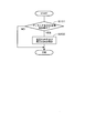
- 10 is a flowchart showing a control flow of a low pressure EGR valve and a high pressure EGR valve according to a fourth embodiment.
- 10 is a flowchart showing a control flow of a low pressure EGR valve and a high pressure EGR valve according to a fifth embodiment.
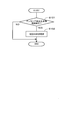
- 10 is a flowchart showing a control flow of an ammonia-derived compound addition valve according to Embodiment 6.
- 10 is a flowchart showing a control flow of an ammonia-derived compound addition valve according to Embodiment 7.
- 10 is a flowchart showing a control flow of an ammonia-derived compound addition valve according to Embodiment 8.
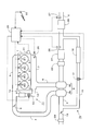
- FIG. 1 is a diagram showing a schematic configuration of an internal combustion engine and its intake / exhaust system according to the present embodiment.
- the internal combustion engine 1 is a diesel engine for driving a vehicle having four cylinders 2.
- Each cylinder 2 is provided with a fuel injection valve 3 that directly injects fuel into the cylinder 2.
- the intake manifold 5 and the exhaust manifold 7 are connected to the internal combustion engine 1.
- An intake passage 4 is connected to the intake manifold 5.
- An exhaust passage 6 is connected to the exhaust manifold 7.
- a compressor 8 a of a turbocharger 8 is installed in the intake passage 4.
- a turbine 8 b of a turbocharger 8 is installed in the exhaust passage 6.
- a first throttle valve 9 is provided in the intake passage 4 downstream of the compressor 8a.
- An air flow meter 29 and a second throttle valve 19 are provided upstream of the compressor 8 a in the intake passage 4.
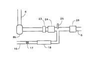
- an oxidation catalyst 23, a particulate filter 24, and a selective reduction type NOx catalyst 26 are sequentially provided from the upstream side along the flow of the exhaust gas on the downstream side of the turbine 8 b.
- an ammonia-derived compound addition valve 25 that adds an ammonia-derived compound to the exhaust gas is provided between the particulate filter 24 and the selective reduction type NOx catalyst 26 in the exhaust passage 6.
- the ammonia-derived compound added from the ammonia-derived compound addition valve 25 is supplied to the selective reduction type NOx catalyst 26 as a reducing agent.
- the addition of the ammonia-derived compound from the ammonia-derived compound addition valve 25 is executed at predetermined intervals during the operation of the internal combustion engine 1. Part of the ammonia-derived compound supplied to the selective reduction type NOx catalyst 26 is adsorbed by the selective reduction type NOx catalyst 26. When the addition of the ammonia-derived compound from the ammonia-derived compound addition valve 25 is stopped, NOx is reduced using the ammonia-derived compound adsorbed on the selective reduction type NOx catalyst 26 as a reducing agent.
- the ammonia-derived compound may be added in any state of gas, liquid or solid.
- the ammonia-derived compound addition valve 25 corresponds to the ammonia-derived compound addition means according to the present invention.
- the intake / exhaust system of the internal combustion engine 1 is provided with a high pressure EGR device 11 and a low pressure EGR device 15.
- the high pressure EGR device 11 includes a high pressure EGR passage 12, a high pressure EGR valve 13, and a high pressure EGR cooler 14.
- One end of the high pressure EGR passage 12 is connected to the exhaust manifold 7, and the other end is connected to the downstream side of the first throttle valve 9 in the intake passage 4.
- the high-pressure EGR valve 13 and the high-pressure EGR cooler 14 are provided in the high-pressure EGR passage 12.
- the flow rate of the high pressure EGR gas introduced from the exhaust manifold 7 to the intake passage 4 through the high pressure EGR passage 12 is controlled by the high pressure EGR valve 13.
- the low pressure EGR device 15 includes a low pressure EGR passage 16, a low pressure EGR valve 17, and a low pressure EGR cooler 18.
- One end of the low pressure EGR passage 16 is connected downstream of the ammonia-derived compound addition valve 25 in the exhaust passage 6 and upstream of the selective reduction type NOx catalyst 26, and the other end is the second throttle valve in the intake passage 4. 19 and downstream of the compressor 8a and upstream of the compressor 8a.
- the low pressure EGR valve 17 and the low pressure EGR cooler 18 are provided in the low pressure EGR passage 16.
- the flow rate of the low-pressure EGR gas introduced from the exhaust passage 6 into the intake passage 4 through the low-pressure EGR passage 16 is controlled by the low-pressure EGR valve 17.
- the high pressure EGR valve 13 is provided downstream of the high pressure EGR cooler 14 in the high pressure EGR passage 12, and the low pressure EGR valve 17 is downstream of the low pressure EGR cooler 18 in the low pressure EGR passage 16. Is provided. However, the high pressure EGR valve 13 may be provided upstream of the high pressure EGR cooler 14 in the high pressure EGR passage 12, and the low pressure EGR valve 17 is provided upstream of the low pressure EGR cooler 18 in the low pressure EGR passage 16. May be. Regardless of the arrangement of the EGR valves 13 and 17 in the EGR passages 12 and 16, it is possible to control the EGR valves 13 and 17 described later.
- a temperature sensor 27 for detecting the temperature of the exhaust gas is provided downstream of the selective reduction type NOx catalyst 26 in the exhaust passage 6. Further, a NOx sensor 28 that detects the NOx concentration of the exhaust gas is provided on the exhaust passage 6 downstream of the particulate filter 24 and upstream of the connection portion of the low pressure EGR passage 16.
- An electronic control unit (ECU) 20 is provided in the internal combustion engine 1 configured as described above.
- An air flow meter 29, a temperature sensor 27, a NOx sensor 28, a crank position sensor 21 and an accelerator opening sensor 22 are electrically connected to the ECU 20. These output signals are input to the ECU 20.
- the crank position sensor 21 is a sensor that detects the crank angle of the internal combustion engine 1.
- the accelerator opening sensor 22 is a sensor that detects the accelerator opening of a vehicle on which the internal combustion engine 1 is mounted.
- the fuel injection valve 3, the first throttle valve 9, the second throttle valve 19, the ammonia-derived compound addition valve 25, the high pressure EGR valve 13 and the low pressure EGR valve 17 are electrically connected to the ECU 20. These are controlled by the ECU 20.
- the ECU 20 estimates the amount of NOx in the exhaust based on the amount of intake air detected by the air flow meter 29 and the NOx concentration of the exhaust detected by the NOx sensor 28. Further, the ECU 20 determines the addition amount when adding the ammonia-derived compound from the ammonia-derived compound addition valve 25 based on the calculated NOx amount and the exhaust temperature detected by the temperature sensor 27.
- ammonia-derived compound addition valve 25 corresponds to the ammonia-derived compound addition means according to the present invention.
- EGR valve control In this embodiment, when an ammonia-derived compound is added from the ammonia-derived compound addition valve 25, the ammonia-derived compound is connected to the low pressure EGR passage 16 in the exhaust passage 6 (hereinafter simply referred to as a low pressure EGR passage connection portion). Pass through. At this time, if the low-pressure EGR valve 17 is opened and the low-pressure EGR gas is introduced into the intake passage 4, a part of the ammonia-derived compound may flow into the low-pressure EGR passage 16 together with the exhaust gas. .
- the low-pressure EGR valve 17 is closed. Thereby, the circulation of EGR gas in the low pressure EGR passage 16 is stopped. Therefore, the inflow of the ammonia-derived compound into the low pressure EGR passage 16 can be suppressed. As a result, corrosion of EGR system parts such as the low pressure EGR valve 17 and the low pressure EGR cooler 18 can be suppressed. Further, the inflow of the ammonia-derived compound into the intake passage 4 is suppressed. Therefore, corrosion of the engine parts such as the intake system parts such as the housing and the impeller of the compressor 8a and the first throttle valve 9 and the valve seat and piston ring can be suppressed.
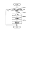
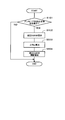
- Control flow A control flow of the low pressure EGR valve according to the present embodiment will be described based on the flowchart shown in FIG. This flow is stored in advance in the ECU 20 and is repeatedly executed by the ECU 20 during operation of the internal combustion engine 1.
- step S101 it is determined whether or not the addition of the ammonia-derived compound from the ammonia-derived compound addition valve 25 is executed. If an affirmative determination is made in step S101, the process of step S102 is executed next. If a negative determination is made, the execution of this flow is temporarily terminated.
- step S102 the low pressure EGR valve 17 is closed. Thereafter, the execution of this flow is temporarily terminated.
- the ECU 20 that executes the process of step S102 in the above flow corresponds to the suppressing means according to the present invention.
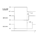
- FIG. 3 is a diagram showing command signals from the ECU 20 to the ammonia-derived compound addition valve 25 and the low-pressure EGR valve 17.
- the low pressure EGR valve 17 is closed when the addition of the ammonia-derived compound from the ammonia-derived compound addition valve 25 is started. Then, after the addition of the ammonia-derived compound from the ammonia-derived compound addition valve 25 is stopped, the low-pressure EGR valve 17 is opened after a predetermined period ⁇ td has elapsed, and the introduction of the low-pressure EGR gas into the intake passage 4 is resumed.
- the predetermined period ⁇ td is a period corresponding to the time lag.
- the predetermined period ⁇ td may be determined based on the exhaust gas flow rate.
- the valve closing timing of the low-pressure EGR valve 17 may be after the elapse of a predetermined period ⁇ td from the start of the addition of the ammonia-derived compound, similarly to the valve opening timing.
- the low-pressure EGR valve 17 when the ammonia-derived compound is added from the ammonia-derived compound addition valve 25, the low-pressure EGR valve 17 is fully closed, so that the ammonia-derived compound is supplied to the low-pressure EGR passage 16 and the intake passage 4. Inflow can be reliably suppressed. However, depending on the operating state of the internal combustion engine 1, it may be difficult to stop the supply of the low pressure EGR gas to the internal combustion engine 1. In such a case, the low pressure EGR valve 17 does not necessarily have to be fully closed. If the opening degree of the low-pressure EGR valve 17 is reduced when the ammonia-derived compound addition valve 25 is added, the EGR gas flowing through the low-pressure EGR passage 16 is smaller than when the ammonia-derived compound is not added. The flow rate can be reduced. Thereby, inflow of the ammonia-derived compound into the low pressure EGR passage 16 and the intake passage 4 can be suppressed.
- the flow rate of the EGR gas flowing through the low-pressure EGR passage 16 is controlled by control other than the reduction of the opening degree of the low-pressure EGR valve 17. It may be reduced.
- the flow rate of the EGR gas flowing through the low pressure EGR passage 16 can also be reduced by increasing the opening degree of the second throttle valve 19.
- an exhaust throttle valve is provided downstream of the selective reduction type NOx catalyst 26 in the exhaust passage 6 (that is, downstream of the connection portion of the low pressure EGR passage 16 in the exhaust passage 6)
- the exhaust throttle valve The flow rate of the EGR gas flowing through the low pressure EGR passage 16 can also be reduced by increasing the opening degree.
- the flow rate of the EGR gas flowing through the low pressure EGR passage 16 is executed by combining the opening degree reduction control of the low pressure EGR valve 17, the opening degree increase control of the second throttle valve 19, and the exhaust throttle valve opening degree increase control. May be reduced.
- (Modification) 4 to 6 are diagrams showing modifications of the configuration of the exhaust system of the internal combustion engine according to the present embodiment. 4 to 6, the NOx sensor 28 and the temperature sensor 27 are omitted.
- the ammonia-derived compound addition valve 25 is provided upstream of the oxidation catalyst 23 in the exhaust passage 6.
- the ammonia-derived compound addition valve 25 is provided at a position that is substantially the same position in the exhaust passage 6 as the connection portion of the low-pressure EGR passage 16 in the exhaust flow direction and faces the opening of the low-pressure EGR passage 16. It has been. 4 or 5, at least a part of the ammonia-derived compound added from the ammonia-derived compound addition valve 25 reaches the connection portion of the low-pressure EGR passage 16.
- the ammonia-derived compound addition valve 25 is provided downstream of the connection portion of the low pressure EGR passage 16 in the exhaust passage 6, if the position is in the vicinity of the connection portion, the exhaust pulsation In some cases, at least a part of the ammonia-derived compound added from the ammonia-derived compound addition valve 25 reaches the connection portion of the low-pressure EGR passage 16 due to the exhaust gas being drawn into the low-pressure EGR passage 16.
- the ammonia-derived compound addition valve 25 is downstream of the connection portion of the low-pressure EGR passage 16 in the exhaust passage 6, and at least a part of the added ammonia-derived compound is in the connection portion of the low-pressure EGR passage 16. It is provided within the reachable range.
- FIG. 7 is a diagram showing a schematic configuration of the internal combustion engine and its intake / exhaust system according to the present embodiment.
- the arrangement of the ammonia-derived compound addition valve 25 in the exhaust system is different from that in the first embodiment.
- an ammonia-derived compound addition valve 25 is provided upstream of the connection portion of the high pressure EGR passage 12 in the exhaust manifold 7 along the flow of exhaust gas.
- EGR valve control In this embodiment, when an ammonia-derived compound is added from the ammonia-derived compound addition valve 25, the ammonia-derived compound is not only connected to the connection portion of the low-pressure EGR passage 16 in the exhaust passage 6 but also the high-pressure EGR passage 12 in the exhaust manifold 7. Pass through the connection. At this time, when the ammonia-derived compound reaches the connection portion of the high pressure EGR passage 12 in the exhaust manifold 7, the high pressure EGR valve 13 is opened, and the high pressure EGR gas is introduced into the intake passage 4. Then, a part of the ammonia-derived compound may flow into the high-pressure EGR passage 12 together with the exhaust gas.
- Control flow A control flow of the low pressure EGR valve and the high pressure EGR valve according to the present embodiment will be described based on a flowchart shown in FIG. This flow is stored in advance in the ECU 20 and is repeatedly executed by the ECU 20 during operation of the internal combustion engine 1. This flow is obtained by replacing step S102 in the flow shown in FIG. 2 with step S202. Therefore, only step S202 will be described.
- step S202 the process of step S202 is executed.
- step S202 the low pressure EGR valve 17 and the high pressure EGR valve 13 are closed. Thereafter, the execution of this flow is temporarily terminated.
- the ECU 20 that executes the process of step S202 in the above flow corresponds to the suppressing means according to the present invention.
- FIG. 9 is a diagram showing command signals from the ECU 20 to the ammonia-derived compound addition valve 25, the high pressure EGR valve 13, and the low pressure EGR valve 17.
- the high pressure EGR valve 13 and the low pressure EGR valve 17 are closed when the addition of the ammonia-derived compound from the ammonia-derived compound addition valve 25 is started.
- the high-pressure EGR valve 13 is opened, and the introduction of the high-pressure EGR gas into the intake passage 4 is resumed.
- the low pressure EGR valve 17 is opened after the second predetermined period ⁇ td2 has elapsed since the addition of the ammonia derived compound from the ammonia derived compound addition valve 25 is stopped, and the introduction of the low pressure EGR gas into the intake passage 4 is resumed.
- the ammonia-derived compound is added from the ammonia-derived compound addition valve 25, and then the ammonia-derived compound is connected to the high pressure EGR passage 12 in the exhaust manifold 7 (hereinafter simply referred to as the high pressure EGR passage connection portion). It is a period corresponding to a time lag until it reaches ().
- the second predetermined period ⁇ td2 is a period corresponding to a time lag from when the ammonia-derived compound is added from the ammonia-derived compound addition valve 25 to when the ammonia-derived compound reaches the low pressure EGR passage connection.
- the high-pressure EGR valve 13 is closed for the first predetermined period ⁇ td1 and the low-pressure EGR valve 17 is closed for the predetermined period ⁇ td. 12 and the low pressure EGR passage 16 can be further suppressed.
- the first and second predetermined periods ⁇ td1 and ⁇ td2 may be determined based on the flow rate of the exhaust gas.
- the valve closing timing of the high-pressure EGR valve 13 may be the time after the first predetermined period ⁇ td1 has elapsed since the start of the addition of the ammonia-derived compound, similarly to the valve opening timing.
- the valve closing timing of the low pressure EGR valve 17 may be the time after the second predetermined period ⁇ td2 has elapsed since the start of the addition of the ammonia-derived compound, similarly to the valve opening timing.
- the high-pressure EGR valve 13 and the low-pressure EGR valve 17 do not necessarily need to be fully closed. If the opening degree of the high-pressure EGR valve 13 is reduced when the ammonia-derived compound is added from the ammonia-derived compound addition valve 25, the EGR gas flowing through the high-pressure EGR passage 12 is smaller than when the ammonia-derived compound is not added. The flow rate can be reduced. Thereby, inflow of the ammonia-derived compound into the high-pressure EGR passage 12 and the intake passage 4 can be suppressed.
- the opening degree of the low pressure EGR valve 17 is reduced when the ammonia derived compound is added from the ammonia derived compound addition valve 25, the low pressure EGR passage 16 and the intake air of the ammonia derived compound are reduced. Inflow to the passage 4 can be suppressed.
- the flow rate of the EGR gas flowing through the high-pressure EGR passage 12 is controlled by control other than the reduction of the opening degree of the high-pressure EGR valve 13. It may be reduced.
- the flow rate of the EGR gas flowing through the high pressure EGR passage 12 can also be reduced by increasing the opening degree of the first throttle valve 9.
- the second throttle valve 19 instead of or in addition to the control of the low pressure EGR valve 17, the second throttle valve 19, the exhaust throttle valve, and the like are controlled so that the ammonia-derived compound addition valve 25 When the ammonia-derived compound is added, the flow rate of the EGR gas flowing through the low pressure EGR passage 16 may be reduced.
- the configuration according to the present embodiment may be a configuration in which the ammonia-derived compound addition valve 25 is provided in the exhaust port connected to any one of the four cylinders 2.
- FIG. 10 is a diagram showing a schematic configuration of the internal combustion engine and its intake and exhaust system according to the present embodiment.
- the connection position of one end of the low pressure EGR passage 16 in the exhaust passage 6 is different from that in the first embodiment.
- one end of the low-pressure EGR passage 16 is connected to the downstream side of the selective reduction type NOx catalyst 26 in the exhaust passage 6.
- EGR valve control According to the configuration according to the present embodiment, compared with the case where the low pressure EGR passage 16 is connected to the upstream side of the selective reduction type NOx catalyst 26 in the exhaust passage 6, it is derived from ammonia added from the ammonia-derived compound addition valve 25. It is difficult for the compound to flow into the low pressure EGR passage 16. However, some of the ammonia-derived compounds added from the ammonia-derived compound addition valve 25 and supplied to the selective reduction-type NOx catalyst 26 are not used for the reduction of NOx in the selective reduction-type NOx catalyst 26, but are selectively reduced. In some cases, the fuel flows out downstream of the NOx catalyst 26.
- the ammonia-derived compound flowing out from the selective reduction type NOx catalyst 26 may flow into the low pressure EGR passage 16. Therefore, also in this embodiment, when the ammonia-derived compound is added from the ammonia-derived compound addition valve 25, the opening degree of the low-pressure EGR valve 17 is reduced in order to reduce the flow rate of the EGR gas flowing through the low-pressure EGR passage 16.
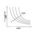
- FIG. 11 is a graph showing the relationship between the adsorption amount of the ammonia-derived compound in the selective reduction type NOx catalyst 26, the catalyst temperature, and the exhaust gas flow rate.
- the vertical axis represents the adsorption amount of the ammonia-derived compound
- the horizontal axis represents the temperature of the selective reduction type NOx catalyst 26.
- the adsorption amount of the ammonia-derived compound in the selective reduction type NOx catalyst 26 changes according to the temperature of the selective reduction type NOx catalyst 26 and the flow rate of the exhaust gas.
- the outflow amount of the ammonia-derived compound from the selective reduction type NOx catalyst 26 varies depending on the temperature of the selective reduction type NOx catalyst 26, the flow rate of the exhaust gas, and the like. That is, the outflow amount of the ammonia-derived compound from the selective reduction type NOx catalyst 26 increases as the temperature of the selective reduction type NOx catalyst 26 increases and the exhaust gas flow rate increases.
- the opening degree of the low pressure EGR valve 17 is increased. That is, when the amount of the ammonia-derived compound flowing out downstream of the selective reduction type NOx catalyst 26 is small, the flow rate of the EGR gas flowing through the low pressure EGR passage 16 is increased as compared with the case where the amount is large. According to this, it is possible to suppress the decrease in the amount of low-pressure EGR gas as much as possible while suppressing the inflow of the ammonia-derived compound into the low-pressure EGR passage 16.
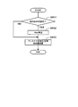
- Control flow A control flow of the low pressure EGR valve according to the present embodiment will be described based on a flowchart shown in FIG. This flow is stored in advance in the ECU 20 and is repeatedly executed by the ECU 20 during operation of the internal combustion engine 1. In this flow, step S102 in the flow shown in FIG. 2 is replaced with steps S302 to S304. Therefore, only steps S302 to S304 will be described.
- step S302 the process of step S302 is executed next.
- step S302 the outflow amount Qao of the ammonia-derived compound from the selective reduction NOx catalyst 26 when the ammonia-derived compound is added from the ammonia-derived compound addition valve 25 is calculated.
- the ECU 20 stores in advance a map showing the relationship between the adsorption amount of the ammonia-derived compound in the selective reduction type NOx catalyst 26, the catalyst temperature, and the exhaust gas flow rate as shown in FIG.
- the outflow amount Qao of the ammonia-derived compound is calculated based on the adsorption amount of the ammonia-derived compound obtained using the map and the addition amount of the ammonia-derived compound from the ammonia-derived compound addition valve 25.
- the temperature of the selective reduction type NOx catalyst 26 can be estimated based on the detection value of the temperature sensor 27. Further, the flow rate of the exhaust gas can be estimated based on the detected value of the air flow meter 29 or the like.
- a NOx sensor for detecting the NOx concentration of the exhaust may be provided before or after the selective reduction type NOx catalyst 26 in the exhaust passage 6 or downstream of the selective reduction type NOx catalyst 26.
- the outflow amount Qao of the ammonia-derived compound may be calculated based on the change in the detected value of the NOx sensor when the addition of the ammonia-derived compound from the ammonia-derived compound addition valve 25 is executed. .
- a reduction amount ⁇ Rlv of the low pressure EGR valve 17 is calculated based on the current operating state of the internal combustion engine 1 and the outflow amount Qao of the ammonia-derived compound.
- the relationship between the operating state of the internal combustion engine 1 and the outflow amount Qao of the ammonia-derived compound and the reduction amount ⁇ Rlv of the opening degree of the low pressure EGR valve 17 is stored in advance in the ECU 20 as a map. In the map, the smaller the outflow amount Qao of the ammonia-derived compound, the smaller the amount of reduction ⁇ Rlv of the opening of the low pressure EGR valve 17 is.
- an opening reduction amount ⁇ Rlv of the low pressure EGR valve 17 is calculated using the map.
- step S304 the opening degree of the low pressure EGR valve 17 is reduced by the reduction amount ⁇ Rlv calculated in step S303. Thereafter, the execution of this flow is temporarily terminated.
- the operating state of the internal combustion engine 1 is divided into a region where the outflow amount Qao of the ammonia-derived compound when the ammonia-derived compound is added from the ammonia-derived compound addition valve 25 is relatively large and a region where the amount is relatively small.
- the map may be stored in the ECU 20 in advance. Then, the reduction amount ⁇ Rlv of the opening degree of the low pressure EGR valve 17 corresponding to each region may be determined in advance.
- the amount of reduction ⁇ Rlv of the opening of the low pressure EGR valve 17 corresponding to the region where the outflow amount Qao of the ammonia-derived compound is relatively small is the low pressure EGR valve 17 corresponding to the region where the outflow amount Qao of the ammonia-derived compound is relatively large. Is set to a value smaller than the reduction amount ⁇ Rlv of the opening. Then, the reduction amount ⁇ Rlv of the opening of the low-pressure EGR valve 17 is determined depending on which region the operating state of the internal combustion engine 1 at the time of adding the ammonia-derived compound from the ammonia-derived compound addition valve 25 belongs.
- the ECU 20 that executes the process of step S304 in the above flow corresponds to the suppressing means according to the present invention.
- the exhaust throttle valve, and the like are controlled so that the ammonia-derived compound addition valve 25 When the ammonia-derived compound is added, the flow rate of the EGR gas flowing through the low pressure EGR passage 16 may be reduced. Also in this case, when the amount of the ammonia-derived compound flowing out downstream of the selective reduction type NOx catalyst 26 is small, the flow rate of the EGR gas flowing through the low-pressure EGR passage 16 is increased compared to when the amount is large.
- the opening degree of the second throttle valve 19 and the exhaust throttle valve is controlled.
- EGR valve control Depending on the operating state of the internal combustion engine 1, it may be difficult to supply a sufficient amount of EGR gas to the internal combustion engine 1 by the high pressure EGR device 11. In such a case, even when the ammonia-derived compound is added from the ammonia-derived compound addition valve 25, it is necessary to ensure the supply of the EGR gas by the low-pressure EGR device 15. In this embodiment, in such a case, the low pressure EGR valve 17 is not fully closed, but the opening degree is reduced. This ensures a minimum amount of low-pressure EGR gas.
- the ammonia-derived compound does not enter the low pressure EGR passage 16 unless the low pressure EGR valve 17 is fully closed and the flow of the EGR gas in the low pressure EGR passage 16 is stopped. There is a possibility of inflow.
- the ammonia-derived compound When the ammonia-derived compound is supplied to the internal combustion engine 1 via the low-pressure EGR passage 16, the ammonia-derived compound may be discharged from the internal combustion engine 1 to the exhaust manifold 7 together with the exhaust gas.
- the high-pressure EGR valve 13 is opened and high-pressure EGR gas is introduced into the intake passage 4, the ammonia-derived compound discharged to the exhaust manifold 7 may flow into the high-pressure EGR passage 12. There is.
- the high-pressure EGR valve 13 is closed to close the high-pressure EGR valve 13. The flow of EGR gas in the passage 12 is stopped. Thereby, even when the ammonia-derived compound is discharged from the internal combustion engine 1, the ammonia-derived compound can be prevented from flowing into the high-pressure EGR passage 12.
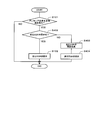
- Control flow A control flow of the low pressure EGR valve and the high pressure EGR valve according to the present embodiment will be described based on a flowchart shown in FIG. This flow is stored in advance in the ECU 20 and is repeatedly executed by the ECU 20 during operation of the internal combustion engine 1. This flow is obtained by adding steps S402 to S404 to the flow shown in FIG. Therefore, only steps S402 to S404 will be described.
- step S101 if an affirmative determination is made in step S101, the process of step S402 is executed next.
- step S402 based on the operating state of the internal combustion engine 1, it is determined whether or not the low pressure EGR valve 17 can be fully closed. If an affirmative determination is made in step S402, the process of step S102 is executed next. If a negative determination is made, the process of step S403 is executed next.
- Step S403 the opening degree is reduced without closing the low pressure EGR valve 17. At this time, a reduction amount of the opening degree of the low pressure EGR valve 17 is set based on the required low pressure EGR gas amount.
- step S404 the high pressure EGR valve 13 is closed. Thereafter, the execution of this flow is temporarily terminated.
- the high pressure EGR valve 13 does not necessarily have to be fully closed. If the opening degree of the high-pressure EGR valve 13 is reduced when the ammonia-derived compound is added from the ammonia-derived compound addition valve 25, the EGR gas flowing through the high-pressure EGR passage 12 is smaller than when the ammonia-derived compound is not added. The flow rate can be reduced. Thereby, inflow of the ammonia-derived compound into the high-pressure EGR passage 12 can be suppressed.
- the ECU 20 that executes the processes of steps S102, S403, and S404 in the above flow corresponds to the suppression means according to the present invention.
- the second throttle valve 19 instead of or in addition to the control of the low pressure EGR valve 17, the second throttle valve 19, the exhaust throttle valve, and the like are controlled so that the ammonia-derived compound addition valve 25 When the ammonia-derived compound is added, the flow rate of the EGR gas flowing through the low pressure EGR passage 16 may be reduced.
- the ammonia-derived compound is added from the ammonia-derived compound addition valve 25 by controlling the first throttle valve 9 or the like instead of or in addition to the control of the high-pressure EGR valve 13, The flow rate of EGR gas flowing through the high-pressure EGR passage 12 may be reduced.
- EGR valve control In the present embodiment, as in the first embodiment, when the ammonia-derived compound is added from the ammonia-derived compound addition valve 25, the low-pressure EGR valve 17 is closed and the flow of the EGR gas in the low-pressure EGR passage 16 is stopped. At this time, the flow rate of the EGR gas flowing through the high pressure EGR passage 12 is increased by increasing the opening degree of the high pressure EGR valve 13. That is, the amount of high-pressure EGR gas introduced into the intake passage 4 is increased. As a result, it is possible to suppress a decrease in the amount of EGR gas supplied to the internal combustion engine 1 due to the stop of the introduction of the low pressure EGR gas into the intake passage 4.
- Control flow A control flow of the low pressure EGR valve and the high pressure EGR valve according to the present embodiment will be described based on the flowchart shown in FIG. This flow is stored in advance in the ECU 20 and is repeatedly executed by the ECU 20 during operation of the internal combustion engine 1. This flow is obtained by adding steps S503 and S504 to the flow shown in FIG. Therefore, only steps S503 and S504 will be described.
- step S503 the process of step S503 is executed after step S102.
- step S503 an increase amount ⁇ Rhv of the opening degree of the high pressure EGR valve 13 is calculated.
- the increase amount ⁇ Rhv of the opening degree of the high pressure EGR valve 13 is calculated as a value capable of increasing the high pressure EGR gas amount by the amount of the low pressure EGR gas before the low pressure EGR valve 17 is closed.
- the relationship between the increase amount ⁇ Rhv of the opening degree of the high pressure EGR valve 13 and the low pressure EGR gas amount before the low pressure EGR valve 17 is closed is stored in advance in the ECU 20 as a map.
- step S503 an increase amount ⁇ Rhv of the opening degree of the high pressure EGR valve 13 is calculated using the map.
- the opening degree of the high pressure EGR valve 13 is increased to the upper limit value, it may be difficult to increase the high pressure EGR gas amount by the amount of the low pressure EGR gas before the low pressure EGR valve 17 is closed. In this case, it is good also considering the increase amount of the opening degree of the high pressure EGR valve 13 as a value from which the opening degree becomes an upper limit value.
- step S504 the opening degree of the high pressure EGR valve 13 is increased by the increase amount ⁇ Rhv calculated in step S503. Thereafter, the execution of this flow is temporarily terminated.
- the low-pressure EGR valve 17 does not necessarily need to be fully closed. Even in this case, if the opening degree of the low pressure EGR valve 17 is reduced, the low pressure EGR gas amount is reduced. Therefore, as described above, the opening degree of the high pressure EGR valve 13 is increased to compensate for the decrease amount of the low pressure EGR gas amount.
- the ECU 20 that executes the processes of steps S102 and S504 in the above flow corresponds to the suppressing means according to the present invention.
- the flow rate of the EGR gas flowing through the high-pressure EGR passage 12 is controlled by control other than the increase in the opening degree of the high-pressure EGR valve 13. It may be increased.
- the flow rate of the EGR gas flowing through the high pressure EGR passage 12 can be increased also by reducing the opening degree of the first throttle valve 9.
- the second throttle valve 19 instead of or in addition to the control of the low pressure EGR valve 17, the second throttle valve 19, the exhaust throttle valve, and the like are controlled so that the ammonia-derived compound addition valve 25 When the ammonia-derived compound is added, the flow rate of the EGR gas flowing through the low pressure EGR passage 16 may be reduced.
- the condition for introducing low-pressure EGR gas into the intake passage 4 is satisfied. Stops adding the ammonia-derived compound from the ammonia-derived compound addition valve 25, and then opens the low-pressure EGR valve 17. Further, when the low pressure EGR valve 17 is opened and the low pressure EGR gas is being introduced into the intake passage 4, when it is time to add the ammonia derived compound from the ammonia derived compound addition valve 25, The addition of the ammonia-derived compound is prohibited until the introduction of the low pressure EGR gas into the intake passage 4 is stopped.
- the addition of the ammonia-derived compound from the ammonia-derived compound addition valve 25 is always performed. May be.
- Control flow A control flow of the ammonia-derived compound addition valve according to the present embodiment will be described based on a flowchart shown in FIG. This flow is stored in advance in the ECU 20 and is repeatedly executed by the ECU 20 during operation of the internal combustion engine 1.
- step S601 it is determined whether or not the low pressure EGR valve 17 is open, that is, whether or not the low pressure EGR gas is being introduced into the intake passage 4. If an affirmative determination is made in step S601, the process of step S602 is executed next, and if a negative determination is made, execution of this flow is temporarily terminated.
- step S602 addition of the ammonia-derived compound from the ammonia-derived compound addition valve 25 is prohibited. Thereafter, the execution of this flow is temporarily terminated.
- the addition of the ammonia derived compound from the ammonia derived compound addition valve 25 is prohibited, so that the low pressure EGR passage of the ammonia derived compound is prevented. 16 and the intake passage 4 can be reliably suppressed.
- the addition of the ammonia-derived compound from the ammonia-derived compound addition valve 25 is not necessarily prohibited. If the addition amount of the ammonia-derived compound is decreased as compared with the case where the low-pressure EGR gas is not introduced into the intake passage 4 (when the low-pressure EGR valve 17 is in the fully closed state), the low-pressure EGR passage of the ammonia-derived compound is reduced. 16 and the inflow to the intake passage 4 can be suppressed.
- the ECU 20 that executes the process of step S602 in the above flow corresponds to the suppressing means according to the present invention.
- Example 7 A seventh embodiment of the present invention will be described with reference to FIG. Here, only differences from the sixth embodiment will be described.
- ammonia-derived compound addition control In the present embodiment, not only when the low pressure EGR gas is introduced into the intake passage 4, but also when the high pressure EGR gas is introduced into the intake passage 4 by opening the high pressure EGR valve 13. Also, the addition of the ammonia-derived compound from the ammonia-derived compound addition valve 25 is prohibited. Also by this, similarly to Example 2, the inflow of the ammonia-derived compound into the low pressure EGR passage 16 and the high pressure EGR passage 12 can be suppressed.
- the condition for executing the introduction of the high-pressure EGR gas into the intake passage 4 is as follows.
- the addition of the ammonia-derived compound from the ammonia-derived compound addition valve 25 is stopped, and then the high-pressure EGR valve 13 is opened.
- the high pressure EGR valve 13 is opened and the high pressure EGR gas is being introduced into the intake passage 4, when it is time to add the ammonia derived compound from the ammonia derived compound addition valve 25, The addition of the ammonia-derived compound is prohibited until the introduction of the high-pressure EGR gas into the intake passage 4 is stopped.
- Control flow A control flow of the ammonia-derived compound addition valve according to the present embodiment will be described based on a flowchart shown in FIG. This flow is stored in advance in the ECU 20 and is repeatedly executed by the ECU 20 during operation of the internal combustion engine 1. This flow is obtained by adding step S702 to the flow shown in FIG. Therefore, only step S702 will be described.
- step S601 if a negative determination is made in step S601, the process of step S702 is executed next.
- step S702 it is determined whether or not the high pressure EGR valve 13 is open, that is, whether or not high pressure EGR gas is being introduced into the intake passage 4. If an affirmative determination is made in step S702, then the process of step S602 is executed next. If a negative determination is made, execution of this flow is temporarily terminated.
- the ECU 20 that executes the process of step S602 in the above flow corresponds to the suppressing means according to the present invention.
- Example 6 the addition of the ammonia-derived compound from the ammonia-derived compound addition valve 25 is not necessarily prohibited. If the addition amount of the ammonia-derived compound is reduced as compared with the case where the high-pressure EGR gas is not introduced into the intake passage 4 (when the high-pressure EGR valve 13 is in the fully closed state), the high-pressure EGR passage of the ammonia-derived compound is reduced. 12 and the intake passage 4 can be suppressed.
- ammonia-derived compound addition control Also in this embodiment, when the low-pressure EGR valve 17 is opened and the low-pressure EGR gas is introduced into the intake passage 4, the ammonia is lower than when the low-pressure EGR gas is not introduced. The amount of ammonia-derived compound added from the derived compound addition valve 25 is reduced.
- the outflow amount of the ammonia-derived compound from the selective reduction type NOx catalyst 26 varies according to the temperature of the selective reduction type NOx catalyst 26, the flow rate of the exhaust gas, and the like. Therefore, in this embodiment, when the amount of ammonia-derived compound added from the ammonia-derived compound addition valve 25 is reduced, when the amount of ammonia-derived compound flowing out downstream of the selective reduction type NOx catalyst 26 is small, The addition amount of the ammonia-derived compound is increased as compared with the case where the amount is large. According to this, it is possible to suppress the decrease in the supply amount of the ammonia-derived compound to the selective reduction NOx catalyst 26 as much as possible while suppressing the inflow of the ammonia-derived compound into the low pressure EGR passage 16.
- Control flow A control flow of the ammonia-derived compound addition valve according to the present embodiment will be described based on a flowchart shown in FIG. This flow is stored in advance in the ECU 20 and is repeatedly executed by the ECU 20 during operation of the internal combustion engine 1. This flow is obtained by replacing step S602 in the flow shown in FIG. 15 with steps S802 and S803. Therefore, only steps S802 and S803 will be described.
- step S802 the process of step S802 is executed.
- step S802 the amount of ammonia-derived compound added so that the amount of ammonia-derived compound outflow from the selective reduction type NOx catalyst 26 when the ammonia-derived compound addition valve 25 is added from the ammonia-derived compound addition valve 25 becomes the upper limit of the allowable range (hereinafter referred to as the amount of addition). Qad is calculated.
- the ECU 20 stores in advance a map showing the relationship between the outflow upper limit addition amount Qad, the temperature of the selective reduction type NOx catalyst 26, and the exhaust gas flow rate.
- the outflow upper limit addition amount Qad becomes larger as the temperature of the selective reduction type NOx catalyst 26 is lower and the flow rate of exhaust gas is smaller.
- the outflow upper limit addition amount Qad is calculated using the map.
- step S803 the addition amount of the ammonia-derived compound from the ammonia-derived compound addition valve 25 is reduced to the outflow upper limit addition amount Qad calculated in step S802. Thereafter, the execution of this flow is temporarily terminated.
- the ECU 20 that executes the process of step S803 in the above flow corresponds to the suppressing means according to the present invention.
Landscapes
- Engineering & Computer Science (AREA)
- Chemical & Material Sciences (AREA)
- Combustion & Propulsion (AREA)
- Mechanical Engineering (AREA)
- General Engineering & Computer Science (AREA)
- Chemical Kinetics & Catalysis (AREA)
- Health & Medical Sciences (AREA)
- Toxicology (AREA)
- Exhaust Gas After Treatment (AREA)
- Exhaust-Gas Circulating Devices (AREA)
- Output Control And Ontrol Of Special Type Engine (AREA)
Abstract
Description
内燃機関の排気系に一端が接続され該内燃機関の吸気系に他端が接続されたEGR通路を有し、該EGR通路を介して、排気系を流れる排気の一部をEGRガスとして吸気系に導入するEGR装置と、
排気系に設けられた選択還元型NOx触媒と、
排気中に還元剤たるアンモニア由来化合物を添加するものであって、排気系における前記選択還元型NOx触媒よりも上流側且つ添加したアンモニア由来化合物の少なくとも一部が前記EGR通路の接続部に到達する位置に配置されたアンモニア由来化合物添加手段と、
該アンモニア由来化合物添加手段から添加されたアンモニア由来化合物の前記EGR通路への流入を抑制する抑制手段と、
を備えることを特徴とする内燃機関の制御システム。
本発明の実施例1について図1~6に基づいて説明する。
図1は、本実施例に係る内燃機関およびその吸排気系の概略構成を示す図である。内燃機関1は4つの気筒2を有する車両駆動用のディーゼルエンジンである。各気筒2には該気筒2内に燃料を直接噴射する燃料噴射弁3が設けられている。
本実施例においては、アンモニア由来化合物添加弁25からアンモニア由来化合物が添加されると、該アンモニア由来化合物が排気通路6における低圧EGR通路16の接続部(以下、単に低圧EGR通路接続部と称する)を通過する。このとき、低圧EGR弁17が開弁されており、低圧EGRガスの吸気通路4への導入が行なわれていると、アンモニア由来化合物の一部が排気と共に低圧EGR通路16に流入する虞がある。
本実施例に係る低圧EGR弁の制御フローについて図2に示すフローチャートに基づいて説明する。本フローは、ECU20に予め記憶されており、ECU20によって内燃機関1の運転中繰り返し実行される。
図3は、アンモニア由来化合物添加弁25及び低圧EGR弁17へのECU20からの指令信号を示す図である。図3に示すように、本実施例では、アンモニア由来化合物添加弁25からのアンモニア由来化合物の添加開始時に低圧EGR弁17が閉弁される。そして、アンモニア由来化合物添加弁25からのアンモニア由来化合物の添加が停止されてから所定期間Δtd経過後に、低圧EGR弁17が開弁され、低圧EGRガスの吸気通路4への導入が再開される。
図4~6は、本実施例に係る内燃機関の排気系の構成の変形例を示す図である。尚、図4~6においては、NOxセンサ28及び温度センサ27が省略されている。図4においては、アンモニア由来化合物添加弁25が、排気通路6における酸化触媒23より上流側に設けられている。図5においては、アンモニア由来化合物添加弁25が、排気通路6における低圧EGR通路16の接続部と排気の流れ方向において略同一の位置であって低圧EGR通路16の開口部と対向する位置に設けられている。図4又は5のような構成であっても、アンモニア由来化合物添加弁25から添加されたアンモニア由来化合物の少なくとも一部は低圧EGR通路16の接続部に到達する。
本発明の実施例2について図7~9に基づいて説明する。尚、ここでは、実施例1と異なる点についてのみ説明する。
図7は、本実施例に係る内燃機関およびその吸排気系の概略構成を示す図である。本実施例では、排気系におけるアンモニア由来化合物添加弁25の配置が実施例1と異なっている。本実施例では、エキゾーストマニホールド7における高圧EGR通路12の接続部よりも排気の流れに沿って上流側にアンモニア由来化合物添加弁25が設けられている。
本実施例においては、アンモニア由来化合物添加弁25からアンモニア由来化合物が添加されると、該アンモニア由来化合物が、排気通路6における低圧EGR通路16の接続部のみならずエキゾーストマニホールド7における高圧EGR通路12の接続部を通過する。このとき、アンモニア由来化合物がエキゾーストマニホールド7における高圧EGR通路12の接続部に到達したときに、高圧EGR弁13が開弁されており、高圧EGRガスの吸気通路4への導入が行なわれていると、アンモニア由来化合物の一部が排気と共に高圧EGR通路12に流入する虞がある。
本実施例に係る低圧EGR弁および高圧EGR弁の制御フローについて図8に示すフローチャートに基づいて説明する。本フローは、ECU20に予め記憶されており、ECU20によって内燃機関1の運転中繰り返し実行される。尚、本フローは、図2に示すフローのステップS102をステップS202に置き換えたものである。そのため、ステップS202についてのみ説明する。
図9は、アンモニア由来化合物添加弁25、高圧EGR弁13及び低圧EGR弁17へのECU20からの指令信号を示す図である。図9に示すように、本実施例では、アンモニア由来化合物添加弁25からのアンモニア由来化合物の添加開始時に高圧EGR弁13及び低圧EGR弁17が閉弁される。そして、アンモニア由来化合物添加弁25からのアンモニア由来化合物の添加が停止されてから第一所定期間Δtd1経過後に、高圧EGR弁13が開弁され、高圧EGRガスの吸気通路4への導入が再開される。また、アンモニア由来化合物添加弁25からのアンモニア由来化合物の添加が停止されてから第二所定期間Δtd2経過後に、低圧EGR弁17が開弁され、低圧EGRガスの吸気通路4への導入が再開される。
本発明の実施例3について図10~12に基づいて説明する。尚、ここでは、実施例1と異なる点についてのみ説明する。
図10は、本実施例に係る内燃機関およびその吸排気系の概略構成を示す図である。本実施例では、排気通路6における低圧EGR通路16の一端の接続位置が実施例1と異なっている。本実施例では、排気通路6における選択還元型NOx触媒26より下流側に低圧EGR通路16の一端が接続されている。
本実施例に係る構成によれば、排気通路6における選択還元型NOx触媒26より上流側に低圧EGR通路16が接続されている場合に比べて、アンモニア由来化合物添加弁25から添加されたアンモニア由来化合物が低圧EGR通路16に流入し難い。しかしながら、アンモニア由来化合物添加弁25から添加され選択還元型NOx触媒26に供給されたアンモニア由来化合物のうちの一部は、選択還元型NOx触媒26におけるNOxの還元に使用されずに該選択還元型NOx触媒26の下流側に流出する場合がある。
本実施例に係る低圧EGR弁の制御フローについて図12に示すフローチャートに基づいて説明する。本フローは、ECU20に予め記憶されており、ECU20によって内燃機関1の運転中繰り返し実行される。尚、本フローは、図2に示すフローのステップS102をステップS302~S304に置き換えたものである。そのため、ステップS302~S304についてのみ説明する。
本発明の実施例4について図13に基づいて説明する。尚、ここでは、実施例1と異なる点についてのみ説明する。
内燃機関1の運転状態によっては、高圧EGR装置11によって十分な量のEGRガスを内燃機関1に供給することが困難な場合がある。このような場合、アンモニア由来化合物添加弁25からアンモニア由来化合物を添加するときであっても、低圧EGR装置15によるEGRガスの供給を確保する必要がある。本実施例では、このような場合は、低圧EGR弁17を全閉状態とはせずに、その開度を低減させる。これによって、必要最低限の低圧EGRガス量を確保する。
本実施例に係る低圧EGR弁および高圧EGR弁の制御フローについて図13に示すフローチャートに基づいて説明する。本フローは、ECU20に予め記憶されており、ECU20によって内燃機関1の運転中繰り返し実行される。尚、本フローは、図2に示すフローにステップS402~S404を加えたものである。そのため、ステップS402~S404についてのみ説明する。
本発明の実施例5について図14に基づいて説明する。尚、ここでは、実施例1と異なる点についてのみ説明する。
本実施例では、実施例1と同様、アンモニア由来化合物添加弁25からアンモニア由来化合物を添加するときに、低圧EGR弁17を閉弁し、低圧EGR通路16におけるEGRガスの流通を停止させる。このとき、高圧EGR弁13の開度を増加させることで、高圧EGR通路12を流通するEGRガスの流量を増加させる。つまり、吸気通路4への高圧EGRガスの導入量を増加させる。これにより、低圧EGRガスの吸気通路4への導入が停止されることに伴う内燃機関1へのEGRガスの供給量の減少を抑制することができる。
本実施例に係る低圧EGR弁および高圧EGR弁の制御フローについて図14に示すフローチャートに基づいて説明する。本フローは、ECU20に予め記憶されており、ECU20によって内燃機関1の運転中繰り返し実行される。尚、本フローは、図2に示すフローにステップS503及びS504を加えたものである。そのため、ステップS503及びS504についてのみ説明する。
本発明の実施例6について図15に基づいて説明する。尚、ここでは、実施例1と異なる点についてのみ説明する。
本実施例においては、低圧EGR弁17が開弁されることで低圧EGRガスの吸気通路4への導入が行なわれるときは、アンモニア由来化合物添加弁25からのアンモニア由来化合物の添加を禁止する。これによっても、実施例1と同様、アンモニア由来化合物の低圧EGR通路16への流入を抑制することができる。
本実施例に係るアンモニア由来化合物添加弁の制御フローについて図15に示すフローチャートに基づいて説明する。本フローは、ECU20に予め記憶されており、ECU20によって内燃機関1の運転中繰り返し実行される。
本発明の実施例7について図16に基づいて説明する。尚、ここでは、実施例6と異なる点についてのみ説明する。
本実施例に係る内燃機関およびその吸排気系の概略構成は、実施例2に係る構成と同様である。
本実施例においては、低圧EGRガスの吸気通路4への導入が行なわれるときのみならず、高圧EGR弁13が開弁されることで高圧EGRガスの吸気通路4への導入が行なわれるときにも、アンモニア由来化合物添加弁25からのアンモニア由来化合物の添加を禁止する。これによっても、実施例2と同様、アンモニア由来化合物の低圧EGR通路16及び高圧EGR通路12への流入を抑制することができる。
本実施例に係るアンモニア由来化合物添加弁の制御フローについて図16に示すフローチャートに基づいて説明する。本フローは、ECU20に予め記憶されており、ECU20によって内燃機関1の運転中繰り返し実行される。尚、本フローは、図15に示すフローにステップS702を加えたものである。そのため、ステップS702についてのみ説明する。
本発明の実施例8について図17に基づいて説明する。尚、ここでは、実施例6と異なる点についてのみ説明する。
本実施例に係る内燃機関およびその吸排気系の概略構成は、実施例3に係る構成と同様である。
本実施例においても、低圧EGR弁17が開弁されることで低圧EGRガスの吸気通路4への導入が行なわれるときは、該低圧EGRガスの導入が行なわれていないときに比べて、アンモニア由来化合物添加弁25からのアンモニア由来化合物の添加量を減量する。
本実施例に係るアンモニア由来化合物添加弁の制御フローについて図17に示すフローチャートに基づいて説明する。本フローは、ECU20に予め記憶されており、ECU20によって内燃機関1の運転中繰り返し実行される。尚、本フローは、図15に示すフローのステップS602をステップS802及びS803に置き換えたものである。そのため、ステップS802及びS803についてのみ説明する。
4・・・吸気通路
5・・・インテークマニホールド
6・・・排気通路
7・・・エキゾーストマニホールド
8・・・ターボチャージャ
8a・・コンプレッサ
8b・・タービン
9・・・第一スロットル弁
10・・パティキュレートフィルタ
11・・高圧EGR装置
12・・高圧EGR通路
13・・高圧EGR弁
14・・高圧EGRクーラ
15・・低圧EGR装置
16・・低圧EGR通路
17・・低圧EGR弁
18・・低圧EGRクーラ
19・・第二スロットル弁
20・・ECU
23・・酸化触媒
24・・パティキュレートフィルタ
25・・アンモニア由来化合物添加弁
26・・選択還元型NOx触媒
27・・温度センサ
28・・NOxセンサ
Claims (9)
- 内燃機関の排気系に一端が接続され該内燃機関の吸気系に他端が接続されたEGR通路を有し、該EGR通路を介して、排気系を流れる排気の一部をEGRガスとして吸気系に導入するEGR装置と、
排気系に設けられた選択還元型NOx触媒と、
排気中に還元剤たるアンモニア由来化合物を添加するものであって、排気系における前記選択還元型NOx触媒よりも上流側且つ添加したアンモニア由来化合物の少なくとも一部が前記EGR通路の接続部に到達する位置に配置されたアンモニア由来化合物添加手段と、
該アンモニア由来化合物添加手段から添加されたアンモニア由来化合物の前記EGR通路への流入を抑制する抑制手段と、
を備えることを特徴とする内燃機関の制御システム。 - 前記抑制手段が、前記アンモニア由来化合物添加手段からアンモニア由来化合物が添加される際に、アンモニア由来化合物が添加されていないときに比べて前記EGR通路を流れるEGRガスの流量を低減させることで、前記アンモニア由来化合物添加手段から添加されたアンモニア由来化合物の前記EGR通路への流入を抑制することを特徴とする請求項1に記載の内燃機関の制御システム。
- 前記EGR通路の一端が、排気系における前記選択還元型NOx触媒よりも下流側に接続されており、
前記抑制手段が、前記EGR通路を流れるEGRガスの流量を低減させるときに、前記選択還元型NOx触媒でのNOxの還元に使用されずに該選択還元型NOx触媒の下流側に流出するアンモニア由来化合物の量が少ない場合は、その量が多い場合に比べてEGRガスの流量を多くすることを特徴とする請求項2に記載の内燃機関の制御システム。 - 前記EGR通路が、排気系におけるターボチャージャのタービンよりも下流側に一端が接続され吸気系におけるターボチャージャのコンプレッサよりも上流側に他端が接続された低圧EGR通路であって、
前記EGR装置が、排気系におけるターボチャージャのタービンよりも上流側に一端が接続され吸気系におけるターボチャージャのコンプレッサよりも下流側に他端が接続された高圧EGR通路を更に有し、
前記抑制手段が、前記アンモニア由来化合物添加手段からアンモニア由来化合物が添加されるときであって前記低圧EGR通路を流れるEGRガスの流量を低減させるときに、前記低圧EGR通路におけるEGRガスの流通を停止させない場合は、前記高圧EGR通路を流れるEGRガスの流量も低減させることを特徴とする請求項2に記載の内燃機関の制御システム。 - 前記EGR通路が、排気系におけるターボチャージャのタービンよりも下流側に一端が接続され吸気系におけるターボチャージャのコンプレッサよりも上流側に他端が接続された低圧EGR通路であって、
前記EGR装置が、排気系におけるターボチャージャのタービンよりも上流側に一端が接続され吸気系におけるターボチャージャのコンプレッサよりも下流側に他端が接続された高圧EGR通路を更に有し、
前記抑制手段が、前記アンモニア由来化合物添加手段からアンモニア由来化合物が添加されるときであって前記低圧EGR通路を流れるEGRガスの流量を低減させるときに、前記高圧EGR通路を流れるEGRガスの流量を増加させることを特徴とする請求項2に記載の内燃機関の制御システム。 - 前記抑制手段が、前記EGR通路を介してEGRガスを吸気系に導入する際に、EGRガスの吸気系への導入を停止しているときに比べて前記アンモニア由来化合物添加手段からのアンモニア由来化合物の添加量を減量することで、前記アンモニア由来化合物添加手段から添加されたアンモニア由来化合物の前記EGR通路への流入を抑制することを特徴とする請求項1に記載の内燃機関の制御システム。
- 前記EGR通路の一端が、排気系における前記選択還元型NOx触媒よりも下流側に接続されており、
前記抑制手段が、前記アンモニア由来化合物からのアンモニア由来化合物の添加量を減量するときに、前記選択還元型NOx触媒でのNOxの還元に使用されずに該選択還元型NOx触媒の下流側に流出するアンモニア由来化合物の量が少ない場合は、その量が多い場合に比べてアンモニア由来化合物の添加量を多くすることを特徴とする請求項6に記載の内燃機関の制御システム。 - 前記EGR通路が、排気系におけるターボチャージャのタービンよりも下流側に一端が接続され吸気系におけるターボチャージャのコンプレッサよりも上流側に他端が接続された低圧EGR通路であることを特徴とする請求項1に記載の内燃機関の制御システム。
- 前記EGR通路が、排気系におけるターボチャージャのタービンよりも上流側に一端が接続され吸気系におけるターボチャージャのコンプレッサよりも下流側に他端が接続された高圧EGR通路であることを特徴とする請求項1に記載の内燃機関の制御システム。
Priority Applications (5)
| Application Number | Priority Date | Filing Date | Title |
|---|---|---|---|
| CN2009801612799A CN102482970B (zh) | 2009-09-10 | 2009-09-10 | 内燃机的控制系统 |
| EP09849212.7A EP2476873B1 (en) | 2009-09-10 | 2009-09-10 | Control system for internal combustion engine |
| US13/394,458 US8783014B2 (en) | 2009-09-10 | 2009-09-10 | Control system for internal combustion engine |
| PCT/JP2009/065871 WO2011030433A1 (ja) | 2009-09-10 | 2009-09-10 | 内燃機関の制御システム |
| JP2011530687A JP5403060B2 (ja) | 2009-09-10 | 2009-09-10 | 内燃機関の制御システム |
Applications Claiming Priority (1)
| Application Number | Priority Date | Filing Date | Title |
|---|---|---|---|
| PCT/JP2009/065871 WO2011030433A1 (ja) | 2009-09-10 | 2009-09-10 | 内燃機関の制御システム |
Publications (1)
| Publication Number | Publication Date |
|---|---|
| WO2011030433A1 true WO2011030433A1 (ja) | 2011-03-17 |
Family
ID=43732119
Family Applications (1)
| Application Number | Title | Priority Date | Filing Date |
|---|---|---|---|
| PCT/JP2009/065871 Ceased WO2011030433A1 (ja) | 2009-09-10 | 2009-09-10 | 内燃機関の制御システム |
Country Status (5)
| Country | Link |
|---|---|
| US (1) | US8783014B2 (ja) |
| EP (1) | EP2476873B1 (ja) |
| JP (1) | JP5403060B2 (ja) |
| CN (1) | CN102482970B (ja) |
| WO (1) | WO2011030433A1 (ja) |
Cited By (5)
| Publication number | Priority date | Publication date | Assignee | Title |
|---|---|---|---|---|
| CN103987931A (zh) * | 2011-12-12 | 2014-08-13 | 五十铃自动车株式会社 | 内燃机及其控制方法 |
| WO2014192846A1 (ja) | 2013-05-30 | 2014-12-04 | トヨタ自動車株式会社 | 排気浄化装置の異常診断装置 |
| JP2015172339A (ja) * | 2014-03-11 | 2015-10-01 | 三菱自動車工業株式会社 | 排気浄化システム |
| JP6024823B2 (ja) * | 2013-05-30 | 2016-11-16 | トヨタ自動車株式会社 | 排気浄化装置の異常診断装置 |
| JP2018021499A (ja) * | 2016-08-03 | 2018-02-08 | マツダ株式会社 | エンジンの排気浄化装置 |
Families Citing this family (11)
| Publication number | Priority date | Publication date | Assignee | Title |
|---|---|---|---|---|
| CN102667083B (zh) | 2009-12-08 | 2015-03-25 | 丰田自动车株式会社 | 内燃机的排气净化系统 |
| US20130138324A1 (en) * | 2010-08-10 | 2013-05-30 | Toyota Jidosha Kabushiki Kaisha | Control device for internal combustion engine |
| WO2012164713A1 (ja) * | 2011-06-02 | 2012-12-06 | トヨタ自動車株式会社 | 内燃機関の制御装置 |
| EP2918805B1 (en) * | 2012-11-07 | 2017-06-21 | Toyota Jidosha Kabushiki Kaisha | Exhaust gas purification device for internal-combustion engine |
| DE102013009578A1 (de) * | 2013-06-07 | 2014-12-11 | Man Truck & Bus Ag | Verfahren und Vorrichtung zum Entschwefeln eines Abgasrückstroms |
| US9506426B2 (en) * | 2014-03-24 | 2016-11-29 | Ford Global Technologies, Llc | Methods and systems for recycling engine feedgas cold-start emissions |
| FR3023874B1 (fr) * | 2014-07-16 | 2019-06-28 | Renault S.A.S | Systeme de recirculation basse pression des gaz d'echappement pour moteur a turbocompresseur |
| JP6327199B2 (ja) * | 2015-05-07 | 2018-05-23 | 株式会社デンソー | 内燃機関の低水温冷却装置 |
| DE102016219548B4 (de) | 2015-11-04 | 2023-12-14 | Ford Global Technologies, Llc | Ammoniak-Schlupf-Detektion |
| US9845750B2 (en) * | 2016-01-29 | 2017-12-19 | Ford Global Technologies, Llc | Method and system for exhaust gas heat recovery |
| KR20210150180A (ko) * | 2020-06-03 | 2021-12-10 | 현대자동차주식회사 | Scr용 우레아 분사 제어방법 및 시스템 |
Citations (6)
| Publication number | Priority date | Publication date | Assignee | Title |
|---|---|---|---|---|
| JPH11324661A (ja) * | 1998-05-15 | 1999-11-26 | Toyota Motor Corp | 内燃機関の排気浄化装置 |
| JP2000297704A (ja) * | 1999-04-12 | 2000-10-24 | Toyota Motor Corp | 内燃機関の排気浄化装置 |
| JP2001280125A (ja) * | 2000-03-31 | 2001-10-10 | Toyota Motor Corp | 内燃機関の排気浄化装置 |
| JP2004324630A (ja) * | 2003-04-28 | 2004-11-18 | Tokyo Denshi Service:Kk | ディーゼルエンジンの排気ガス浄化装置 |
| JP2007162501A (ja) * | 2005-12-09 | 2007-06-28 | Toyota Motor Corp | 内燃機関の排気浄化システム |
| JP2008184925A (ja) * | 2007-01-29 | 2008-08-14 | Toyota Motor Corp | 内燃機関のegrシステム |
Family Cites Families (16)
| Publication number | Priority date | Publication date | Assignee | Title |
|---|---|---|---|---|
| JP3465490B2 (ja) | 1996-09-09 | 2003-11-10 | トヨタ自動車株式会社 | 内燃機関の排気浄化装置 |
| EP1138891B8 (en) | 2000-03-31 | 2007-03-07 | Toyota Jidosha Kabushiki Kaisha | Exhaust emission control system of internal combustion engine |
| DE10054877A1 (de) | 2000-11-06 | 2002-05-29 | Omg Ag & Co Kg | Abgasreinigungsanlage für die selektive katalytische Reduktion von Stickoxiden unter mageren Abgasbedingungen und Verfahren zur Abgasreinigung |
| JP2004270565A (ja) * | 2003-03-10 | 2004-09-30 | Hino Motors Ltd | ディーゼルエンジンの排ガス浄化システム |
| DE10315593B4 (de) * | 2003-04-05 | 2005-12-22 | Daimlerchrysler Ag | Abgasnachbehandlungseinrichtung und -verfahren |
| JP2006125247A (ja) | 2004-10-27 | 2006-05-18 | Hitachi Ltd | エンジンの排気ガス浄化方法及び排気ガス浄化装置 |
| US7681394B2 (en) * | 2005-03-25 | 2010-03-23 | The United States Of America, As Represented By The Administrator Of The U.S. Environmental Protection Agency | Control methods for low emission internal combustion system |
| JP4542455B2 (ja) * | 2005-03-28 | 2010-09-15 | 三菱ふそうトラック・バス株式会社 | 内燃機関の排気浄化装置 |
| DE102005045029A1 (de) * | 2005-09-22 | 2007-03-29 | Man Nutzfahrzeuge Ag | Mittels Abgasturbolader aufgeladene Brennkraftmaschine mit einem Abgasstrang mit SCR-Katalysator(en) |
| JP4232823B2 (ja) * | 2006-12-26 | 2009-03-04 | トヨタ自動車株式会社 | 内燃機関の排気浄化装置 |
| US20080202101A1 (en) * | 2007-02-23 | 2008-08-28 | Driscoll James J | Exhaust treatment system |
| JP4730336B2 (ja) | 2007-05-22 | 2011-07-20 | トヨタ自動車株式会社 | 内燃機関の排気再循環制御装置 |
| JP4961336B2 (ja) | 2007-12-20 | 2012-06-27 | 三菱ふそうトラック・バス株式会社 | エンジンの排気浄化装置 |
| US8151558B2 (en) * | 2008-01-31 | 2012-04-10 | Caterpillar Inc. | Exhaust system implementing SCR and EGR |
| US8424289B2 (en) * | 2009-02-23 | 2013-04-23 | GM Global Technology Operations LLC | Technique for production of ammonia on demand in a three way catalyst for a passive selective catalytic reduction system |
| US8347609B2 (en) * | 2009-12-23 | 2013-01-08 | Ford Global Technologies, Llc | Methods and systems for emission system control |
-
2009
- 2009-09-10 CN CN2009801612799A patent/CN102482970B/zh not_active Expired - Fee Related
- 2009-09-10 WO PCT/JP2009/065871 patent/WO2011030433A1/ja not_active Ceased
- 2009-09-10 JP JP2011530687A patent/JP5403060B2/ja not_active Expired - Fee Related
- 2009-09-10 US US13/394,458 patent/US8783014B2/en not_active Expired - Fee Related
- 2009-09-10 EP EP09849212.7A patent/EP2476873B1/en not_active Not-in-force
Patent Citations (6)
| Publication number | Priority date | Publication date | Assignee | Title |
|---|---|---|---|---|
| JPH11324661A (ja) * | 1998-05-15 | 1999-11-26 | Toyota Motor Corp | 内燃機関の排気浄化装置 |
| JP2000297704A (ja) * | 1999-04-12 | 2000-10-24 | Toyota Motor Corp | 内燃機関の排気浄化装置 |
| JP2001280125A (ja) * | 2000-03-31 | 2001-10-10 | Toyota Motor Corp | 内燃機関の排気浄化装置 |
| JP2004324630A (ja) * | 2003-04-28 | 2004-11-18 | Tokyo Denshi Service:Kk | ディーゼルエンジンの排気ガス浄化装置 |
| JP2007162501A (ja) * | 2005-12-09 | 2007-06-28 | Toyota Motor Corp | 内燃機関の排気浄化システム |
| JP2008184925A (ja) * | 2007-01-29 | 2008-08-14 | Toyota Motor Corp | 内燃機関のegrシステム |
Non-Patent Citations (1)
| Title |
|---|
| See also references of EP2476873A4 * |
Cited By (15)
| Publication number | Priority date | Publication date | Assignee | Title |
|---|---|---|---|---|
| US9422848B2 (en) * | 2011-12-12 | 2016-08-23 | Isuzu Motors Limited | Internal combustion engine and control method for same |
| US20140325963A1 (en) * | 2011-12-12 | 2014-11-06 | Isuzu Motors Limited | Internal combustion engine and control method for same |
| CN103987931A (zh) * | 2011-12-12 | 2014-08-13 | 五十铃自动车株式会社 | 内燃机及其控制方法 |
| CN103987931B (zh) * | 2011-12-12 | 2016-09-07 | 五十铃自动车株式会社 | 内燃机及其控制方法 |
| JP6024823B2 (ja) * | 2013-05-30 | 2016-11-16 | トヨタ自動車株式会社 | 排気浄化装置の異常診断装置 |
| AU2014271738B2 (en) * | 2013-05-30 | 2016-06-16 | Toyota Jidosha Kabushiki Kaisha | Abnormality diagnosis apparatus of exhaust gas purification apparatus |
| CN105339618A (zh) * | 2013-05-30 | 2016-02-17 | 丰田自动车株式会社 | 排气净化装置的异常诊断装置 |
| JP6015855B2 (ja) * | 2013-05-30 | 2016-10-26 | トヨタ自動車株式会社 | 排気浄化装置の異常診断装置 |
| WO2014192846A1 (ja) | 2013-05-30 | 2014-12-04 | トヨタ自動車株式会社 | 排気浄化装置の異常診断装置 |
| US9617938B2 (en) | 2013-05-30 | 2017-04-11 | Toyota Jidosha Kabushiki Kaisha | Abnormality diagnosis apparatus of exhaust gas purification apparatus |
| RU2623321C1 (ru) * | 2013-05-30 | 2017-06-23 | Тойота Дзидося Кабусики Кайся | Устройство диагностирования неисправности для прибора контроля выхлопных газов |
| RU2624308C1 (ru) * | 2013-05-30 | 2017-07-03 | Тойота Дзидося Кабусики Кайся | Устройство диагностики неисправности устройства очистки выхлопного газа |
| CN105339618B (zh) * | 2013-05-30 | 2017-11-28 | 丰田自动车株式会社 | 排气净化装置的异常诊断装置 |
| JP2015172339A (ja) * | 2014-03-11 | 2015-10-01 | 三菱自動車工業株式会社 | 排気浄化システム |
| JP2018021499A (ja) * | 2016-08-03 | 2018-02-08 | マツダ株式会社 | エンジンの排気浄化装置 |
Also Published As
| Publication number | Publication date |
|---|---|
| EP2476873B1 (en) | 2016-11-30 |
| EP2476873A1 (en) | 2012-07-18 |
| US8783014B2 (en) | 2014-07-22 |
| EP2476873A4 (en) | 2014-10-08 |
| CN102482970A (zh) | 2012-05-30 |
| CN102482970B (zh) | 2013-12-11 |
| JP5403060B2 (ja) | 2014-01-29 |
| US20120159934A1 (en) | 2012-06-28 |
| JPWO2011030433A1 (ja) | 2013-02-04 |
Similar Documents
| Publication | Publication Date | Title |
|---|---|---|
| JP5403060B2 (ja) | 内燃機関の制御システム | |
| JP6317114B2 (ja) | 過給機付きエンジンの制御装置 | |
| EP2133524B1 (en) | Apparatus for purifying exhaust gas in internal combustion engine | |
| EP2685072B1 (en) | Control device for internal combustion engine | |
| US20160084206A1 (en) | Diesel engine and method of controlling same | |
| JP6071799B2 (ja) | エンジンの排気還流装置のための故障検出装置 | |
| JP2008309053A (ja) | 内燃機関の制御装置 | |
| EP2284369B1 (en) | Diagnosis apparatus for reducing agent supply apparatus | |
| JP2008002351A (ja) | 内燃機関の排気還流装置 | |
| JP2010174695A (ja) | NOxセンサの故障診断システム及び故障診断方法 | |
| JP2007162500A (ja) | 内燃機関の排気浄化システム | |
| US8225596B2 (en) | Exhaust purification device of internal combustion engine | |
| JP4826503B2 (ja) | 内燃機関の排気制御装置 | |
| JP6319561B2 (ja) | 排気浄化システム | |
| EP2677150A2 (en) | Exhaust gas control apparatus of internal combustion engine | |
| EP3071806B1 (en) | Exhaust gas control apparatus and exhaust gas control method for internal combustion engine | |
| JP5771911B2 (ja) | 圧縮着火内燃機関の自動停止再始動システム | |
| JP4877159B2 (ja) | 内燃機関のegr制御システム | |
| JP2017129027A (ja) | 圧縮自着火式内燃機関の制御システム | |
| EP2891776B1 (en) | Additive supply device for internal combustion engines | |
| JP2007120455A (ja) | 内燃機関の排気浄化システム | |
| JP4654880B2 (ja) | 内燃機関の排気浄化システム | |
| JP2015042848A (ja) | エンジンの排気還流装置 |
Legal Events
| Date | Code | Title | Description |
|---|---|---|---|
| WWE | Wipo information: entry into national phase |
Ref document number: 200980161279.9 Country of ref document: CN |
|
| 121 | Ep: the epo has been informed by wipo that ep was designated in this application |
Ref document number: 09849212 Country of ref document: EP Kind code of ref document: A1 |
|
| WWE | Wipo information: entry into national phase |
Ref document number: 13394458 Country of ref document: US |
|
| REEP | Request for entry into the european phase |
Ref document number: 2009849212 Country of ref document: EP |
|
| WWE | Wipo information: entry into national phase |
Ref document number: 2011530687 Country of ref document: JP Ref document number: 2009849212 Country of ref document: EP |
|
| NENP | Non-entry into the national phase |
Ref country code: DE |