WO2011030448A1 - 逆開きスライドファスナー - Google Patents
逆開きスライドファスナー Download PDFInfo
- Publication number
- WO2011030448A1 WO2011030448A1 PCT/JP2009/065943 JP2009065943W WO2011030448A1 WO 2011030448 A1 WO2011030448 A1 WO 2011030448A1 JP 2009065943 W JP2009065943 W JP 2009065943W WO 2011030448 A1 WO2011030448 A1 WO 2011030448A1
- Authority
- WO
- WIPO (PCT)
- Prior art keywords
- butterfly
- slider
- side edge
- sliding contact
- stick
- Prior art date
- Legal status (The legal status is an assumption and is not a legal conclusion. Google has not performed a legal analysis and makes no representation as to the accuracy of the status listed.)
- Ceased
Links
Images




Classifications
-
- A—HUMAN NECESSITIES
- A44—HABERDASHERY; JEWELLERY
- A44B—BUTTONS, PINS, BUCKLES, SLIDE FASTENERS, OR THE LIKE
- A44B19/00—Slide fasteners
- A44B19/24—Details
- A44B19/26—Sliders
-
- A—HUMAN NECESSITIES
- A44—HABERDASHERY; JEWELLERY
- A44B—BUTTONS, PINS, BUCKLES, SLIDE FASTENERS, OR THE LIKE
- A44B19/00—Slide fasteners
- A44B19/24—Details
- A44B19/38—Means at the end of stringer by which the slider can be freed from one stringer, e.g. stringers can be completely separated from each other
- A44B19/384—Separable slide fasteners with quick opening devices
- A44B19/388—Bottom end stop means for quick opening slide fasteners
-
- A—HUMAN NECESSITIES
- A44—HABERDASHERY; JEWELLERY
- A44B—BUTTONS, PINS, BUCKLES, SLIDE FASTENERS, OR THE LIKE
- A44B19/00—Slide fasteners
- A44B19/24—Details
- A44B19/38—Means at the end of stringer by which the slider can be freed from one stringer, e.g. stringers can be completely separated from each other
-
- Y—GENERAL TAGGING OF NEW TECHNOLOGICAL DEVELOPMENTS; GENERAL TAGGING OF CROSS-SECTIONAL TECHNOLOGIES SPANNING OVER SEVERAL SECTIONS OF THE IPC; TECHNICAL SUBJECTS COVERED BY FORMER USPC CROSS-REFERENCE ART COLLECTIONS [XRACs] AND DIGESTS
- Y10—TECHNICAL SUBJECTS COVERED BY FORMER USPC
- Y10T—TECHNICAL SUBJECTS COVERED BY FORMER US CLASSIFICATION
- Y10T24/00—Buckles, buttons, clasps, etc.
- Y10T24/25—Zipper or required component thereof
- Y10T24/2509—Plural independently movable sliders
Definitions
- the present invention relates to a reverse-opening slide fastener that can be opened upward and reversely and that can be opened and closed.
- a slide-and-insertion type slide fastener having a box bar and a butterfly bar at the lower end of the dentition is used.
- a butterfly bar In a general slide fastener with a separation fitting, a butterfly bar is continuously provided at the lower end of one service tooth row, and a box for inserting the butterfly bar is connected to the lower end of the other service tooth row. It is installed.
- the butterfly bar In this slide fastener with a separable insertion tool, the butterfly bar is configured so that it can be inserted into and removed from the box and slider in the state where the slider is lowered to the lowest end in contact with the box.
- the fastener stringer can be separated.
- Patent Document 1 describes a reverse-opening slide fastener that can be opened from both the upper and lower sides by arranging the rear openings of two sliders so as to face each other. A break-away insert has been proposed.
- the reverse opening slide fastener described in Patent Document 1 includes an upper slider and a lower slider for enabling opening and closing from both above and below, and at the lower end of the dentition row of one fastener stringer, In the state where the upper slider and the lower slider are lowered to the lowermost end of the reverse opening slide fastener and the rear openings are brought into contact with each other, a butterfly bar that can be inserted into and removed from the upper slider and the lower slider is provided. Further, a box bar having a stopper for locking the lower slider at the lowermost end is attached to the lower end of the dentition row of the opposite fastener stringer.
- FIG. 11 is a partially enlarged view of the butt stick of the separation / insertion tool described in FIG. 6 of Patent Document 1 and a fastener stringer in the vicinity where the wing stick is attached.
- FIG. 12 shows a state in the middle of reinserting the butterfly bar 930 once extracted from the upper slider 50 and the lower slider 60 into the upper slider 50 and the lower slider 60 in the reverse opening slide fastener described in Patent Document 1.
- the direction in which the butterfly stick 930 and the box stick 40 are attached is down (D direction) among the longitudinal directions of the fastener stringers 916 and 17.
- the direction opposite to the downward direction (D direction) is defined as the upward direction (U direction).
- the right side of the fastener stringers 916 and 17 is defined as the R direction and the left side as the L direction in the upward direction (U direction).
- the first fastener stringer 916 includes a fastener tape 11 having a core portion 14 formed on an opposing end edge, and a first row of first service teeth 12 attached to the core portion 14 at a predetermined pitch.
- a butterfly pin 930 provided continuously below the first service tooth 12 row (D direction) and a reinforcing film 24 for improving rigidity and strength in the vicinity of the butterfly rod 930 are arranged.
- a flange sliding contact side edge 930F is formed on the right edge (R direction side edge) of the butterfly stick 930 shown in FIG. 11, and the opposite side edge 930C is formed on the left edge (L direction side edge) of the butterfly stick 930. Is formed.
- a top end wall 930 ⁇ / b> D having a flat portion perpendicular to the longitudinal direction of the first fastener stringer 916 is formed at the tip of the opposing side edge 930 ⁇ / b> C.
- the extension line EL obtained by extending the flange sliding contact side edge 930F downward (in the D direction) intersected with the top end wall 930D in a direction substantially orthogonal to the top end wall 930D.
- the intersection between the extension line EL and the top end wall 930D is defined as an intersection ND.
- FIG. 12 is a cut surface substantially parallel to the fastener tape 11, and is a cut surface between the upper wing pieces of the upper slider 50 and the lower slider 60 and the first and second fastener stringers 916, 17.
- FIG. 5 is a plan sectional view showing the inside of the tooth guide passages 50T and 60T by cutting 50 and the lower slider 60;
- a reverse opening slide fastener 910 shown in FIG. 12 is an opening / closing tool that enables opening and closing of a left front body and a right front body such as a long coat.
- the reverse opening slide fastener 910 includes a pair of left and right fastener tapes 11, core portions 14 formed along opposite edges of the fastener tapes 11, and a predetermined interval so as to sandwich the core portions 14. And a large number of first and second engaging teeth 12 and 13 arranged in a row.
- the reverse opening slide fastener 910 includes an upper slider 50 that allows the first and second engaging teeth 12 and 13 rows to be inserted and allows the upper opening, and a lower slider 60 that allows the reverse opening.
- the rear opening of the upper slider 50 and the rear opening of the lower slider 60 are arranged to face each other.
- a reinforcing film 24 made of a resin film or the like is attached to the front and back of the lower end portions (end portions in the D direction) of the first and second fastener stringers 916 and 17.
- a wing bar 930 and a box bar 40 are connected to the first and second engagement teeth 12 and 13 rows, respectively.
- a hook-like stopper 46 is formed on the lower end (end in the D direction) of the box bar 40.
- the stopper 46 prevents the lower slider 60 from falling off from below by contacting the shoulder portion of the lower slider 60 or the end of the flange 60F when the lower slider 60 is lowered to the lowest end. .
- the stopper 46 is engaged with the lower end of the flange 60 ⁇ / b> F in the lower slider 60 by projecting the stopper 46 in the left direction (L direction) from the lower end of the box bar 40. It is shown.
- the front wing piece (not shown) and the back wing piece 53 of the upper slider 50 shown in FIG. 12 are guided pillars at the upper part (the part in the U direction) of the left and right center (the center part in the LR direction) of the upper slider 50. They are fixed to each other by 50D. From the left and right side edges of the front wing piece and the back wing piece 53 of the upper slider 50, flanges 50F are extended oppositely.
- a service tooth guide passage 50T to be inserted is formed inside the upper slider 50 surrounded by the front wing piece, the back wing piece 53, and the flange 50F.
- a service tooth guide passage 50T to be inserted is formed inside the upper slider 50 surrounded by the front wing piece, the back wing piece 53, and the flange 50F.
- a service tooth guide passage 50T to be inserted is formed inside the upper slider 50 surrounded by the front wing piece, the back wing piece 53, and the flange 50F.
- a service tooth guide passage 50T to be inserted is formed inside the upper slider 50 surrounded by the front wing piece, the back wing piece 53, and the flange 50F.
- a service tooth guide passage 50T to be inserted is formed inside the upper
- a tape insertion path (not shown) is formed in the edge portion of the flange 50F along the edge of the flange 50F.
- the tape insertion passage is a gap through which the fastener tape 11 attached to the first and second engagement teeth 12 and 13 rows inserted through the engagement tooth guide passage 50T is passed. This is the portion where the tape 11 is in sliding contact.
- the lower slider 60 shown in FIG. 12 includes a front wing piece (not shown), a back wing piece 63, a guide post 60D, and a flange 60F. A rear opening and a tape insertion path are formed.
- a handle support (not shown) for supporting the handle of the lower slider 60 in a tiltable manner is formed.
- the removed butterfly bar 930 is attached to the shoulder of the upper slider 50 (FIG. 12). In the example shown in Fig. 4, it is inserted from the right shoulder (R direction shoulder). At this time, after inserting the butterfly stick 930 from the shoulder of the upper slider 50, the butterfly stick 930 is parallel to the box stick 40 in the engagement tooth guide passages 50T and 60T of the upper slider 50 and the lower slider 60. The user grips the vicinity of the reinforcing film 24 below the one fastener stringer 916, and inserts it downward (D direction) while rotating it counterclockwise as shown in FIG.
- a top end wall 930D formed in a shape substantially orthogonal to the extension line EL is It collides from the front with the guide column 60D of the lower slider 60 (particularly near the apex of the guide column 60D).
- the collision with the guide column 60D is in the vicinity of the intersection ND where the top end wall 930D and the extension line EL intersect.
- the butterfly stick 930 cannot be lowered further (D direction). Then, the butterfly stick 930 stops at a position where it collides with the guide column 60D (that is, a position where the butterfly stick 930 does not reach the lowermost end).
- the user may feel that the butterfly stick 930 inserted from the shoulder of the upper slider 50 has stopped, and mistakenly consider that the butterfly stick 930 has been inserted to a predetermined position. If the user determines that the butterfly pin 930 has been inserted to a predetermined position, the user then slides the upper slider 50 upward (U direction) to close the reverse opening slide fastener 910. The operation to move is performed.
- the second attached to the top of the box bar 40 is the second.
- the counterpart first service tooth 12 that should mesh with the service tooth 13 is not lowered to a predetermined position. Therefore, even if the upper slider 50 is slid upward (in the U direction) from the state shown in FIG. 12, the second engagement tooth 13 attached immediately above the box bar 40 is located above the butterfly bar 930.
- the second engagement tooth 13 and the butterfly stick 930 cannot be engaged with each other, and the butterfly stick 930 is caught on the inner surface of the flange 50F of the upper slider 50. Therefore, the upper slider 50 cannot be slid upward (U direction).
- the present invention has been made in view of the above-described problems, and in a reverse opening slide fastener that opens and closes the left and right fastener stringers, the left and right fastener stringers that have been once separated are connected again.
- the purpose of this invention is to provide a reverse-opening slide fastener that can smoothly insert a butterfly stick up to a predetermined position even when the butterfly stick is inserted in a straight line from the shoulder of the upper slider. Yes.
- a reverse opening slide fastener is arranged to face a pair of left and right first and second fastener stringers and lower ends of inner side edge portions of the first and second fastener stringers.
- the tip of the butterfly stick can be inserted beyond the top of the rear pillar side of the guide pillar in the lower slider.
- a first inclined portion that is inclined toward the tip of the butterfly stick in a direction away from the box stick is formed, and the first inclined portion extends the flat portion of the flange sliding contact edge toward the tip of the butterfly stick.
- the first inclined portion is formed at an angle that contacts or separates from the guide column of the lower slider when the butterfly rod is inserted into the upper and lower sliders. It is characterized by having an inclined shape.
- the side surface in the said 1st inclination part of the said box-rod sliding contact side edge is formed in the continuous curved surface.
- a second sloping part that is slanted in a direction away from the box bar toward the tip of the butterfly stick is formed at the flange sliding contact side edge opposite to the first sloping part. It is preferable that the width dimension between the said 1st inclination part in a contact side edge and the said 2nd inclination part in the said flange sliding contact side edge is reducing as it goes to the front-end
- the lower slider has front and back wing pieces connected by the guide pillars, and a stop claw disposed on one of the front and back wing pieces, and a surface on the stop claw side at the tip of the butterfly stick.
- a claw guide slope inclined so as to gradually reduce the thickness of the wing stick toward the tip of the wing stick is formed, and the claw guide slope is preferably arranged across the extension line.
- the butterfly bar includes a box bar sliding contact side edge disposed on the box bar side, and a flange sliding contact side edge disposed on the tape inward side.
- a first inclined portion that is inclined in a direction away from the box bar side toward the tip of the butterfly bar is formed on the sliding contact side edge.
- the first inclined portion formed at the box-sliding contact edge is formed to intersect with an extension line extending the flat portion of the flange-sliding contact edge toward the tip of the butterfly stick, and further, the first inclination The portion has a shape that is inclined at an angle that contacts or separates from the guide column of the lower slider when the butterfly pin is inserted into the upper and lower sliders.
- the first inclined portion at the edge of the box-slider contact side has a shape that is inclined at an angle that is in contact with or apart from the butterfly bar side surface of the guide column in the lower slider.
- the butterfly pin is inserted while being moved straight from the shoulder of the upper slider. Even if it exists, a butterfly stick can be smoothly inserted to the position of the lowest end.
- the base end side of the flange sliding contact edge of the butterfly stick is in sliding contact with the flange of the upper slider and the box stick sliding contact edge.
- the tip end side of the slidably contacts the box bar the top end wall (tip surface) of the butterfly pin collides with the guide column of the lower slider as described above. It was.
- the base end side of the flange sliding contact edge of the butterfly stick is in sliding contact with the flange of the upper slider and the tip end side of the box stick sliding contact edge is in sliding contact with the box stick
- the first inclined part of the bar is in contact with the guide column of the lower slider (especially the side surface of the guide column), and the tip of the butterfly bar is guided in the direction away from the box bar by the inclination of the first inclined part. Inserted beyond the top.
- the tip of the butterfly rod is inserted beyond the top of the rear side of the guide column without the first inclined portion of the butterfly rod colliding with the guide column of the lower slider.
- the butterfly stick can be smoothly inserted to the lowermost position without being stopped by collision with the guide column of the lower slider.
- the lowermost position of the butterfly stick is a position where the tip of the butterfly stick reaches the shoulder opening side from the top of the rear pillar side of the guide pillar in the lower slider, and the butterfly stick is substantially parallel to the box stick.
- the side surface of the guide column refers to the wall surface of the guide column in which the inclination of the surface (the inclination of the tangent when the surface is a curved surface) is 45 ° or less with respect to the length direction of the slider.
- the side surface of the first sloping portion of the box bar sliding side edge (particularly, the side surface facing the guide column of the lower slider in the first sloping portion) can be formed as a continuous curved surface. .
- the tip of the butterfly stick can be more reliably prevented from colliding with the guide pillar of the lower slider, and the butterfly stick can be more smoothly inserted to the lowest end position. be able to.
- the side surface of the first inclined portion is a curved surface, the length of the butterfly stick can be shortened. Therefore, the butterfly bar can be stored in the engagement tooth guide passage of the upper and lower sliders with the lower slider lowered to the lowermost position so that the butterfly bar cannot be seen from the outside.
- the reverse opening slide fastener of the present invention is formed with a second inclined portion inclined at a flange sliding contact side edge of the butterfly pin in a direction away from the box rod side toward the tip of the butterfly rod,
- the width dimension between the 1st inclination part in a contact side edge and the 2nd inclination part in a flange slidable contact side edge can be comprised reducing as it goes to a butterfly stick front-end
- a claw guide slope inclined so as to gradually reduce the thickness of the wing stick toward the tip of the wing stick is formed across the extension line on the surface of the tip of the wing stick.
- the claw guide slope intersects with the extension line and crosses the extension line so that the claw guide slope is combined with the inclined surface (curved surface) of the first inclined portion,
- the surface at the tip of the butterfly stick has a spherical shape.
- FIG. 1 is a plan view of a reverse opening slide fastener according to the present invention.
- FIG. 2 is a cross-sectional plan view of the vicinity of the lower slider in the state where the lower slider is lowered to the lowermost end in the reverse opening slide fastener shown in FIG.
- FIG. 3 is a plan view for explaining the butterfly stick and the box stick in a state where the left and right fastener stringers are separated.
- FIG. 4 is a side view of the butterfly stick shown in FIG. 3 observed from the box stick side, and is a view taken in the direction of arrows IV-IV.
- FIG. 5 is a perspective view of the butterfly stick shown in FIG. 3.
- FIG. 3 is a perspective view of the butterfly stick shown in FIG. 3.
- FIG. 6 is a plan cross-sectional view showing a state in which the upper and lower sliders are lowered to the lowermost end and the butterfly pin is once extracted and then inserted into the upper slider and the lower slider again.
- FIG. 7 is a side view of the state shown in FIG. 6 observed from the box bar side, and is a view taken in the direction of arrows VII-VII.
- FIG. 8 is a diagram showing a state in which the butterfly pin is further inserted from the state shown in FIG. 6 and the vicinity of the tip of the butterfly rod faces the guide column of the lower slider.
- FIG. 9 is an enlarged plan sectional view illustrating the vicinity of the tip of the butterfly stick and the guide column portion shown in FIG. FIG.
- FIG. 10 is a plan sectional view showing a state in which the butterfly stick is inserted to the lowest end.
- FIG. 11 is a partially enlarged view of a butterfly stick and a fastener stringer in the vicinity where the butterfly stick is attached in the conventional separation / insertion tool described in Patent Document 1.
- FIG. FIG. 12 is a diagram showing a state in which the tip of the butterfly stick comes into contact with the guide column of the lower slider when the conventional butterfly stick shown in FIG. 11 is inserted into the upper slider and the lower slider.
- FIG. 1 is a plan view of a reverse opening slide fastener 10 according to the present invention.
- FIG. 2 is a cross-sectional plan view of the vicinity of the lower slider in the state where the lower slider is lowered to the lowermost end in the reverse opening slide fastener shown in FIG.
- FIG. 3 is a plan view for explaining the butterfly stick and the box stick in a state where the left and right fastener stringers are separated.
- FIG. 4 is a side view of the butterfly stick shown in FIG. 3 observed from the box stick side, and is a view taken in the direction of arrows IV-IV.
- FIG. 5 is a perspective view of the butterfly stick shown in FIG. 3.
- a reverse opening slide fastener 10 shown in FIG. 1 is an opening / closing tool that enables opening and closing of a left front body and a right front body such as a jacket and a long coat.
- the reverse-opening slide fastener 10 is attached to a pair of left and right first and second fastener stringers 16 and 17 and opposite edges of the first and second fastener stringers 16 and 17.
- the first and second engagement teeth 12 and 13 can mesh with each other, and meshing is performed when one engaging convex portion enters the other engaging concave portion.
- the first fastener stringer 16 has a plurality of fastener tapes 11 having cores 14 formed on opposite side edges (inner side edges) and a plurality of first tapers 16 arranged at regular intervals so as to sandwich the cores 14. It has a first service tooth 12 row and an upper stopper 18 disposed at one end portion of the first service tooth 12 row.
- the upper stopper 18 is a member for preventing the upper slider 50 from falling off the first engagement tooth 12 row.
- a reinforcing film 24 made of a resin film or the like is attached to the front and back of the fastener tape 11 at the other end portion of the first service tooth 12 row.
- a butterfly pin 30 is continuously provided so as to sandwich the reinforcing film 24 and the core portion 14 together.
- the second fastener stringer 17 includes a plurality of fastener tapes 11 having core portions 14 formed on opposite side edges (inner side edges) and a plurality of first tapers arranged at regular intervals so as to sandwich the core portions 14.
- the upper stopper 18 is a member for preventing the upper slider 50 from falling off the second engagement tooth 13 row.
- a reinforcing film 24 made of a resin film or the like is attached to the front and back of the fastener tape 11 at the other end portion of the second service tooth 13 row.
- a box rod 40 for positioning and holding the lower slider 60 at the lowermost end is continuously provided in such a manner as to sandwich the reinforcing film 24 and the core portion 14 together.
- the butterfly stick 30, the box stick 40 and the lower slider 60 constitute a separation / insertion tool 22.
- the longitudinal direction of the fastener tape 11 is the vertical direction of the reverse opening slide fastener 10, and the upper stopper 18 is arranged for the first and second engagement teeth 12, 13 rows.
- the direction in which the hinge bar 30 and the box bar 40 are arranged is defined as the lower direction (D direction).
- the front side with respect to the paper surface is defined as the front surface of the reverse opening slide fastener 10 (T direction shown in FIG. 4), and the opposite side is the back surface (shown in FIG. 4). B direction).
- the tape width direction of the fastener tape 11 is the left-right direction
- the right side toward the surface (T direction) of the reverse opening slide fastener 10 is the R direction
- the left side is the L direction. It is defined as Here, the U direction and the D direction, the T direction and the B direction, and the R direction and the L direction are opposite to each other.
- a box bar 40 disposed below the second engagement tooth 13 row at the lower end of the opposite edge of the second fastener stringer 17 is formed in an elongated bar shape along the core part 14 of the fastener tape 11, and
- the slider 60 can be positioned at the lowermost end of the second fastener stringer 17, and the butterfly rod 30 inserted into the tooth guide passages of the upper slider 50 and the lower slider 60 can be positioned at the lowermost end.
- the lower slider 60 is disposed closer to the butterfly rod 30 and the box rod 40 than the upper slider 50.
- the upper slider 50 and the lower slider 60 are disposed so that their rear openings face each other. Yes.
- the right edge (side edge in the R direction) of the rod-shaped box bar 40 is arranged on the flange sliding contact side edge 40F arranged on the tape inner side, and the left edge (side edge in the L direction) is arranged on the butterfly stick 30 side.
- the flange sliding contact side edge 40F of the box bar 40 is a portion where the flanges 50F, 60F of the upper and lower sliders 50, 60 are in sliding contact. That is, when the lower slider 60 and the upper slider 50 are slid to the lowermost position, which is the end position on the box bar 40 side, respectively, the tooth guide passages 50T, 60T of the lower slider 60 and the upper slider 50 ( In FIG. 2 and FIGS. 6 to 10 described later, the flanges 50F and 60F are in sliding contact with the flange sliding contact side edge 40F.
- a hook-like stopper 46 is formed at the lower end of the box bar 40 of the second fastener stringer 17 so as to protrude rightward (R direction). As shown in FIG. 2, the shoulder portion of the lower slider 60 lowered to the lowest end comes into contact with the stopper 46. Accordingly, the stopper 46 can prevent the lower slider 60 from dropping from the lower side (D direction).
- the shape of the stopper 46 a shape protruding from the lower end of the box bar 40 in the right direction (R direction) is employed. Accordingly, when the lower slider 60 is slid to the lowermost position, the flange 60F of the shoulder portion of the lower slider 60 can be engaged with the stopper 46.
- the shape of the stopper 46 according to the present invention is not limited to the shape of the stopper 46 shown in FIGS. 2 and 3, and the stopper is moved from the lower end of the box bar to the front direction (T direction) of the slide fastener.
- the portion bulged on the front wing piece 62 or the back wing piece 63 see FIG. 7 described later
- the lower slider 60 may be prevented from falling off from the lower side (D direction) by making contact.
- the opposing side edge 40C of the box bar 40 is an opposing surface that is disposed on the opposite side of the flange sliding contact side edge 40F and faces the butterfly stick 30.
- a triangular piece-like second engagement forming a second locking portion 44 and a guide surface 43.
- a stop guide piece 42 is formed so as to protrude from the opposite side edge 40C.
- locking part 44 has formed in the planar shape the upper side (U direction) side in which the 2nd operation tooth 13 row
- the guide surface 43 has a shape in which the dimension in the width direction gradually increases upward (U direction), and when the lower slider 60 is slid upward (U direction) from the lowermost end, the lower slider 60 This is configured as an inclined guide surface that slides in contact with the guide pillar 60D and opens the lower end portion of the box bar 40 in the right direction (R direction).
- the guide surface 43 is formed as a guide surface that smoothly shifts to the engagement state and the release from the engagement state by the first engagement tooth 12 row and the second engagement tooth 13 row.
- the guide pillars 50D and 60D of the upper and lower sliders 50 and 60 have apexes on the rear side.
- the guide pillars 50D and 60D have an inclined surface that gradually increases the thickness in the width direction from the apex toward the shoulder, and on the shoulder mouth side, the inclined surface that gradually decreases the thickness in the width direction via an inflection point. have.
- the inclined surface on the shoulder opening side has a larger inclination angle than the inclined surface that gradually increases the thickness on the rear opening side.
- the wall surface of the guide pillars 50D and 60D having a tangential inclination greater than 45 ° with respect to the length direction of the slider in the vicinity of the apex.
- the left and right wall surfaces, whose rear surfaces are inclined at 45 ° or less with respect to the slider length direction, are the side surfaces of the guide pillars 50D and 60D.
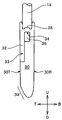
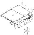
- the butterfly stick 30 disposed below the first engagement tooth 12 row at the lower end portion of the opposing edge of the first fastener stringer 16 is formed in an elongated rod shape along the core portion 14 of the fastener tape 11.
- the tip of the butterfly rod 30 is curved leftward (L direction).
- the left side edge (side edge in the L direction) of the rod-shaped butterfly stick 30 is arranged on the flange sliding contact side edge 30F arranged on the inner side of the tape, and the right side edge (side edge in the R direction) is arranged on the box bar 40 side. It is defined as a box bar sliding contact side edge (opposed side edge) 30C.
- the flange sliding contact side edge 30F of the butterfly bar 30 is the tooth guide guide paths 50T and 60T of the upper slider 50 and the lower slider 60 (see FIG. 2 and FIGS. 6 to 10 described later). ) Are in sliding contact with the flanges 50F and 60F of the upper slider 50 and the lower slider 60 (see FIG. 2 and FIGS. 6 to 10 described later).
- the front side edge (side edge in the T direction) of the butterfly stick 30 is defined as the front wall 30T
- the back side edge (side edge in the B direction) is defined as the back wall 30B.
- the front wall 30T and the back wall 30B of the butterfly pin 30 are provided in the tooth guide passages 50T and 60T of the upper slider 50 and the lower slider 60 (see FIG. 2 and FIGS. 6 to 10 described later). This is a portion that slidably contacts the inner walls (see FIG. 7 described later) of the front blade piece 62 and the back blade piece 53 of the upper slider 50 and the lower slider 60.
- the box bar sliding contact side edge 30C of the butterfly stick 30 is disposed on the opposite side of the flange sliding contact side edge 30F and is a facing surface facing the box stick 40.
- the box bar sliding contact side edge 30C is arranged on the flat part parallel to the tape length direction and on the tip of the butterfly stick with respect to the flat part, and is separated from the box stick 40 side toward the tip of the butterfly stick 30.
- a first inclined portion 30E formed in a shape inclined in the direction to be formed is formed.
- the first inclined portion 30E inserts the butterfly rod 30 into the upper and lower sliders 50, 60, the flange sliding contact side edge 30F of the butterfly rod 30 is in sliding contact with the flange 50F of the upper slider 50, and
- the box bar sliding contact side edge 30C of the butterfly bar 30 is in sliding contact with the opposite side edge 40C of the box bar 40, the lower bar 60 contacts the butterfly side surface of the guide column 60D (or the guide column 60D of the guide column 60D). It has a shape that is inclined at an angle (such as being spaced from the side surface of the butterfly pin side).
- the flange sliding contact side edge 30F is parallel to the tape length direction on the first engagement tooth 12 row side and contacts the flange 50F of the upper slider 50 when the butterfly pin 30 is inserted.
- a second inclined portion 30 ⁇ / b> G that is inclined in a direction away from the box bar 40 toward the tip of the butterfly stick 30.
- the second inclined portion 30G is formed on the opposite side of the first inclined portion 30E on the box bar sliding contact side edge 30C side, and further, the second inclined portion 30G and the box rod sliding contact side edge 30C side.
- the width dimension (the dimension in the LR direction) between the first inclined part 30E and the first inclined part 30E is gradually reduced toward the tip of the butterfly stick 30.
- the second inclined portion 30G on the flange sliding contact side edge 30F side is formed so that the change in the inclination angle is more gradual than the first inclined portion 30E on the box bar sliding contact side edge 30C side. Accordingly, the first inclined portion 30E can be reliably formed while maintaining the strength of the tip of the butterfly pin, and the flange sliding contact edge 30F can interfere with the flange 60F of the lower slider 60 and the like when the butterfly rod 30 is inserted. Can be prevented.
- a straight line when the flat portion of the flange sliding contact side edge 30F that contacts the flange 50F of the upper slider 50 when the butterfly rod 30 is inserted is extended toward the tip of the butterfly rod 30 is defined as an extension line EL.
- the first inclined portion 30E inclined by the box bar sliding contact side edge 30C is formed with an increased inclination so as to intersect the extension line EL.
- the extension line EL is inserted into the upper slider 30 when the butterfly bar 30 is inserted from the shoulder of the upper slider 50 and the box bar sliding contact side edge 30 ⁇ / b> C of the butterfly bar 30 contacts the box bar 40. It is an extension line of the plane part which contacts 50 flanges 50F.
- a position where the inclined box bar sliding contact edge 30C and the extension line EL intersect is defined as an intersection ND.
- the shape of the side surface of the first inclined portion 30E is gradually box-shaped toward the tip of the butterfly rod. It is formed in the shape of a curved surface that is continuously curved so as to be separated from 40.
- the shape of the side surface in the 1st inclination part 30E is not a curved surface shape,
- flexion It is also possible to form a surface shape that is bent in multiple stages at the portion.
- a flat plate-like first engagement with the locking surface directed downward (D direction) is provided on the upper part (U direction part) of the box bar sliding contact side edge 30C of the butterfly stick 30.
- a stop 34 is formed.
- the first locking portion 34 is formed when the butterfly bar 30 once extracted is inserted into the tooth guide passages 50T and 60T of the lower slider 60 and the upper slider 50 arranged at the lowermost end. This is a portion for engaging the second locking portion 44 to stop the butterfly stick 30 at the lowermost end.
- a first locking guide piece 32 in which the front wall 30T is extended in a plan view triangle along the first locking portion 34 is formed on the box bar sliding contact side edge 30C of the butterfly pin 30.
- a guide surface 33 that connects the first locking portion 34 and the box bar sliding contact side edge 30C is formed.
- the guide surface 33 has a shape in which the dimension in the width direction gradually increases upward (U direction), and when the lower slider 60 is slid upward (U direction) from the lowermost end, the lower slider It is formed as a guide surface that slides in contact with the 60 guide pillars 60D and opens the lower end portion of the butterfly stick 30 in the left direction (L direction).
- the first locking guide piece 32 is a part formed by extending the front wall 30T, the butterfly stick 30 and the box stick 40 are placed in the tooth guide passages 50T and 60T of the upper slider 50 and the lower slider 60.
- the second locking guide piece 42 of the box bar 40 can be accommodated on the back surface (direction B) side of the first locking guide piece 32.
- the box stick slide of the butterfly stick 30 is provided.
- a clearance groove 36 is formed in a portion of the contact side edge 30 ⁇ / b> C surrounded by the first locking guide piece 32 and the first locking portion 34.
- the 1st latching guide piece 32 has also played the role which reinforces the 1st latching
- a claw guide slope 39 is formed by gradually tilting the front wall 30T toward the back wall 30B toward the tip of the butterfly stick 30.
- the claw guide slope 39 is a slider with an automatic stop device when the butterfly pin 30 once extracted is inserted into the tooth guide passage 60 ⁇ / b> T of the lower slider 60. It is an inclined surface provided for pushing the stop pawl 64 (see FIG. 2) of the lower slider 60 functioning as the surface (T direction) side and performing a smooth insertion operation.
- the lower slider 60 is slid downward (D direction) from the state shown in FIG. 1, and the first and second engagement teeth 12, 13 rows are engaged with each other.
- the state where 60 is lowered to the lowest end is shown.
- the tip of the butterfly pin 30 and the tip of the box rod 40 of the reverse opening slide fastener 10 are inserted from the top of the guide post 60 ⁇ / b> D of the lower slider 60 to the shoulder opening side.
- the reverse opening slide fastener 10 is configured to have substantially the same position in the longitudinal direction.
- the left and right (LR direction) lengths of the first fastener stringer 16 and the second fastener stringer 17 are aligned and symmetrical, and the appearance can be adjusted. Further, when the lower slider 60 is slid upward (in the U direction), the guide column 60D of the lower slider 60 can be introduced without being caught between the butterfly stick 30 and the box bar 40. Smooth sliding is possible.
- the lower slider 60 is lowered to the lowermost lower end (D direction) and the butterfly stick 30
- the distal end portion and the distal end portion of the box bar 40 can be housed in the tooth guide passage 60T of the lower slider 60 and hidden. Thereby, the external appearance of the reverse opening slide fastener 10 in the state which lowered the lower slider 60 to the lowest end can be prepared.
- FIG. 6 is a side view of the state shown in FIG. 6 observed from the box bar 40 side, and is a view taken along arrow VII-VII shown in FIG.
- FIG. 8 is a diagram showing a state in which the butterfly pin 30 is further inserted from the state shown in FIG. 6 and the vicinity of the tip of the butterfly rod 30 faces the guide column 60D of the lower slider 60.
- FIG. FIG. 9 is an enlarged plan sectional view illustrating the vicinity of the tip of the butterfly stick 30 and the portion of the guide post 60D shown in FIG.
- FIG. 10 is a plan cross-sectional view showing a state in which the butterfly stick 30 is inserted to the lowest end. Note that the same portions as those described in FIGS. 1 to 5 are denoted by the same reference numerals and description thereof is omitted.
- the guide column extends from the center in the left-right direction (LR direction) of the upper portion (U-direction portion) of the back wing piece 53 that forms the bottom of the upper slider 50.
- 50D is standing.
- the guide column 50D has a vertex on the mouth side thereafter, and further has an inclined surface that gradually increases the thickness in the width direction from the vertex toward the shoulder mouth, and on the shoulder mouth side via an inflection point. And an inclined surface for gradually reducing the thickness in the width direction.
- a front blade piece (not shown) is formed on the surface (T direction) side of the guide column 50D.
- a handle (not shown) operated by the user is disposed so as to be freely tilted.
- Left and right flanges 50F are extended from the left and right (LR direction) side edge portions of the front and back wing pieces 53 of the upper slider 50 toward the opposite wing piece side. Inside the slider surrounded by the front wing piece, the back wing piece 53, and the flange 50F, a pair of left and right first service teeth 12 rows and second service teeth 13 rows are inserted in a Y-shaped space in plan view. A tooth guide passage 50T is formed.
- a stop claw 54 when functioning as a slider with an automatic stop device is protruded into the tooth guide guide passage 50T so as to advance and retreat.
- the stop pawl 54 automatically advances into the service gear guide passage 50T by the action of an urging means (not shown), and is engaged with the first service tooth 12 in the meshed state. This is for fixing the position of the upper slider 50 by entering the gap between the rows or the second tooth 13.
- the stop pawl 54 is pulled up from the engagement tooth guide passage 50T against the urging force of the urging means. Then, the stop pawl 54 comes out from the gap between the first service teeth 12 rows or the second service teeth 13 rows, and the fixed upper slider 50 becomes slidable.
- a tape insertion path is formed in the edge portion of the flange 50F along the edge of the flange 50F.
- the tape insertion passage is a gap through which the fastener tape 11 attached to the first and second engagement teeth 12 and 13 rows inserted through the engagement tooth guide passage 50T is passed. This is the portion where the tape 11 is in sliding contact.
- the first state is in a separated state.
- the first and second engagement teeth 12 and 13 are introduced from the left and right shoulders (LR direction) of the upper slider 50.
- the introduced first and second engagement teeth 12 and 13 are guided and merged along the inner wall of the flange 50F of the engagement tooth guide passage 50T to form a meshing state in the lower direction (D direction) shown in FIG. It is discharged from the rear opening.
- the first and second engaging teeth 12 and 13 rows in meshing state are introduced from the rear opening.
- the introduced first and second engagement teeth 12, 13 in the meshed state are separated in the left-right direction (LR direction) along the guide post 50D, and then both upper shoulders (U direction) shown in FIG. Discharged from.
- the guide column is formed from the central part in the left and right direction (LR direction) of the lower part (D direction part) of the back wing piece 63 forming the bottom part of the lower slider 60.
- 60D is standing.
- the guide column 60D has a vertex on the mouth side thereafter, and further has an inclined surface that gradually increases the thickness in the width direction from the vertex toward the shoulder mouth, and on the shoulder mouth side via an inflection point. And an inclined surface for gradually reducing the thickness in the width direction.
- a front blade piece 62 (see FIG. 7) is formed on the surface (T direction) side of the guide post 60D.
- a handle (not shown) operated by the user is disposed so as to be freely tilted.
- Left and right flanges 60F are extended from the left and right (LR direction) side edge portions of the front wing piece 62 and the back wing piece 63 of the lower slider 60 toward the opposite wing piece side.
- a pair of left and right first service teeth 12 rows and second service teeth 13 rows which are Y-shaped spaces in plan view are inserted.
- the service tooth guide passage 60T is formed.
- a stop pawl 64 (see FIGS. 6 to 10) for functioning as a slider with an automatic stop device is projected from the front blade piece 62 so as to be able to advance and retreat in the tooth guide passage 60T.
- the stop pawl 64 automatically advances into the service gear guide passage 60T by the action of an urging means (not shown) and is engaged with the first service tooth 12 in the meshed state. This is for fixing the position of the lower slider 60 by entering the gap between the rows or the second service teeth 13 rows.
- the stop pawl 64 is lifted from the engagement tooth guide passage 60T against the urging force of the urging means. Then, the stop pawl 64 comes out of the gap between the first service teeth 12 rows or the second service teeth 13 rows, and the fixed lower slider 60 becomes slidable.
- a tape insertion path is formed at the edge portion of the flange 60F along the edge of the flange 60F.
- the tape insertion passage is a gap for taking out the fastener tape 11 attached to the first and second engagement teeth 12 and 13 rows inserted into the engagement tooth guide passage 60T from the engagement tooth guide passage 60T to the outside of the lower slider 60. This is the portion where the fastener tape 11 comes into sliding contact when the lower slider 60 slides.
- the upper slider 50 and the lower slider 60 in the reverse opening slide fastener 10 are inserted in the first and second engagement teeth 12 and 13 into the engagement tooth guide passages 50T and 60T, respectively.
- the upper slider 50 is disposed closer to the butterfly stick 30 and the box stick 40, and the rear opening of the upper slider 50 and the rear opening of the lower slider 60 are arranged to face each other.
- the first and second engagement teeth 12 and 13 in mesh are introduced from the rear mouth.
- the introduced first and second engagement teeth 12 and 13 in the meshed state are separated in the left and right direction (LR direction) along the guide post 60D, and then both shoulders in the lower direction (D direction) shown in FIG. Discharged from.
- the lower slider 60 When separating all the meshes between the left and right first and second engagement teeth 12, 13, the lower slider 60 is moved to the lowermost position, and the rear opening of the upper slider 50 is located behind the lower slider 60.
- the upper slider 50 is lowered downward (D direction) to a position where it abuts the mouth. Then, all the first and second engaging teeth 12 and 13 rows are disengaged.
- the reinforcing film 24 at the lower end of the first fastener stringer 16 is gripped, and the butterfly stick 30 is pulled upward (U direction). Then, the butterfly stick 30 can be extracted from the tooth guide passages 50T and 60T of the upper slider 50 and the lower slider 60, and the left and right first fastener stringers 16 and second fastener stringers 17 can be separated.
- the stop claw 64 comes into contact with the front wall 30T at the tip of the butterfly rod 30.
- a claw guide slope 39 in which the front wall 30T is gradually inclined toward the back wall 30B so as to gradually reduce the thickness of the butterfly stick 30 is formed at the tip of the butterfly stick 30.
- the stop claw 64 comes into contact with 39.
- the stop pawl 64 is retracted toward the surface (T direction) (see FIG. 7). In this way, the tip of the butterfly stick 30 can pass through the portion of the lower slider 60 where the stop claw 64 protrudes, and the butterfly stick 30 can be inserted further downward (D direction). .
- the tip of the butterfly pin 30 on which the claw guide inclined surface 39 is formed is formed to be biased toward the back wall 30B side with respect to the center line in the front and back direction of the butterfly rod 30 as shown in FIG. Furthermore, the tip of the butterfly pin 30 is located on the back surface (B direction) side of the protruding end of the stop claw 64 in a state where the stop claw 64 protrudes into the engagement tooth guide passage 60T.
- the claw guide inclined surface 39 is formed continuously at a location where the first inclined portion 30E is formed. That is, the claw guide slope 39 is formed so as to cross the extension line EL, and the claw guide slope 39 is arranged on the surface side of the first inclined portion 30E intersecting with the extension line EL. Yes.
- the surface at the tip portion of the butterfly stick 30 has a spherical shape due to the combination of the claw guide inclined surface 39 and the curved surface of the first inclined portion 30E.
- the stop pawl 64 of the lower slider 60 is surely brought into contact with the pawl guide slope 39. It can be guided to the surface (T direction) side, and the stop pawl 64 can be withdrawn stably.
- the portion where the box bar sliding contact edge 30C of the butterfly stick 30 is closest to the guide pillar 60D of the lower slider 60 is defined as a proximity point CP. Further, when inserting the butterfly stick 30 into the tooth guide passages 50T and 60 of the upper slider 50 and the lower slider 60, the box bar sliding side edge of the butterfly stick 30 facing the guide column 60D of the lower slider 60 is provided.
- the range of the curved shape of 30C is defined as the facing area.
- the butterfly stick 30 as shown in FIG. 8 is inserted, the flange sliding contact side edge 30F of the butterfly stick 30 contacts the flange 50F of the upper slider 50, and the box stick sliding contact edge 30C is the opposite side of the box stick 40.
- a range of the box bar sliding side edge 30C from the contact point with the opposite side edge 40C of the box bar 40 toward the tip of the butterfly bar 30 is defined as a facing area.
- box bar sliding contact side edge 30C and the guide column 60D face each other or face each other, as shown in FIGS. 8 to 10, the surface of the box bar sliding contact side edge 30C of the butterfly bar 30 and the front and back directions of the guide column 60D.
- the wall surfaces forming the (TB direction) face each other, and when those surfaces are vertical, they are not facing each other.
- the butterfly stick 30 and the guide post 60D face each other in a separated state, but may be in contact with each other.
- the proximity point CP in the embodiment shown in FIGS. 8 and 9 is located nearer to the box bar 40 than the intersection ND.
- the user is aware of the reinforcing film 24 at the lower end of the first fastener stringer 916 so that the top end wall 930D of the butterfly pin 930 does not contact the guide column 60D. It was necessary to insert the butterfly stick 930 while rotating.
- the flange sliding contact side edge 930F of the butterfly bar 930 is brought into contact with the flange 50F of the upper slider 50, and the opposite side edge (box bar sliding contact side edge of the butterfly bar 30) is used.
- the first inclined portion 30 ⁇ / b> E of the box bar sliding contact side edge 30 ⁇ / b> C on the tip end side of the butterfly pin 30 is directed toward the tip portion of the butterfly pin 30.
- the inclined surface is formed with a positional relationship with the guide column 60D so that the inclined surface is a facing region facing the guide column 60D of the lower slider 60.
- the inclined surface of the first inclined portion 30E is such that the flange sliding contact side edge 30F of the butterfly stick 30 is in sliding contact with the flange 50F of the upper slider 50, and the box stick sliding contact edge 30C of the butterfly stick 30 is the box stick 40.
- the butterfly stick 30 is spaced from the contact point of the box bar sliding contact side edge 30C with the box bar 40 and the intersection ND that intersects the extension line EL of the box bar sliding contact side edge 30C ( The distance) is configured to be larger than the distance (distance) from the contact point to the apex of the guide column 60D of the lower slider 60.
- the side shape of the first inclined portion 30E of the butterfly stick 30 is formed in a continuous curved surface shape. This reliably prevents the butterfly stick 30 from coming into contact with the guide column 60D of the lower slider 60, thereby enabling a more stable butterfly stick insertion operation.
- the second inclined portion 30G formed on the flange sliding contact side edge 30F side of the butterfly pin 30 is formed more gently than the first inclined portion 30E as described above, the change in inclination angle is formed more slowly. Is inserted, the second inclined portion 30G of the butterfly stick 30 does not contact the flange 60F of the lower slider 60.
- the flange sliding contact side edge 30F of the butterfly rod 30 is inserted into the flange 50F of the upper slider 50 by inserting the butterfly rod 30 while slightly rotating.
- the box bar sliding contact side edge 30C of the butterfly stick 30 may not slide in contact with the opposing side edge 40C of the box bar 40 in some cases.
- the tip of the butterfly pin 30 can be prevented from colliding with the guide column 60D of the lower slider 60, and the butterfly pin insertion operation can be performed smoothly.
- the butterfly stick 30 when the butterfly stick 30 is further inserted downward (D direction) from the state shown in FIGS. 8 and 9, the butterfly stick 30 gradually rotates so as to be parallel to the box stick 40. As shown in FIG. 10, the butterfly stick 30 can be smoothly inserted to the lowest end. Although not shown in FIG. 10, the first locking portion 34 (see FIG. 3) of the butterfly pin 30 abuts on the second locking portion 44 (see FIG. 3) of the box rod 40, thereby 30 can be positioned at the lowest end. Further, that the butterfly stick 30 is parallel to the box bar 40 means that the flat part of the box bar sliding contact side edge 30C or the flat part of the flange sliding contact side edge 30F and the opposite side edge 40C of the box stick 40 are Are parallel to each other.
- the reverse opening slide fastener 10 has a conventional structure in which the tip of the butterfly pin 30 is positioned at the lower slider even when the butterfly pin is inserted at an angle such that the tip of the butterfly pin collides with the guide column of the lower slider. It is possible to reliably avoid the collision with the 60 guide columns 60D and to stably insert the butterfly rod 30 to the lowest end position.
- the tip of the butterfly pin 30 of the reverse opening slide fastener 10 and the tip of the box bar 40 are configured to be substantially in the same position in the longitudinal direction of the reverse opening slide fastener 10.
- the position of the tip of the butterfly pin 30 is lower by the dimension DP from the top (U direction) top (rear side top) of the guide post 60D in the lower slider 60 to the bottom end of the butterfly. It is a position lowered in the (D direction).
- first and second engaging teeth 12 and 13 of the slide fastener 10 metal or resin engaging teeth can be used.
- a coiled service tooth obtained by winding a linear monofilament in a coil shape may be sewn to a fastener tape, and a service tooth that can be normally used as a slide fastener can be used.
- the present invention can be applied to a reverse-opening slide fastener that can be opened upward and reversely and that can be opened and closed.
- Such reverse opening slide fasteners can be used for opening and closing the left and right front bodies of jackets and coats, sportswear, and other uses.
Landscapes
- Slide Fasteners (AREA)
- Cartons (AREA)
- Buckles (AREA)
Abstract
Description
11 ファスナーテープ
12 第1務歯
13 第2務歯
14 芯部
16、916 第1ファスナーストリンガー
17 第2ファスナーストリンガー
18 上止具
22 開離嵌挿具
24 補強フィルム
30、930 蝶棒
30C 箱棒摺接側縁
30E 第1傾斜部
30F、40F、930F フランジ摺接側縁
30G 第2傾斜部
30T 表壁
30B 裏壁
32 第1係止案内片
33、43 案内面
34 第1係止部
36 逃げ溝
37、937 柱案内斜面
38 噛合突起
39 爪案内斜面
40 箱棒
40C、930C 対向側縁
42 第2係止案内片
44 第2係止部
46 ストッパー
50 上スライダー
50D、60D 案内柱
50F、60F フランジ
50T、60T 務歯案内通路
53、63 裏翼片
54、64 停止爪
60 下スライダー
62 表翼片
64 停止爪
930D 頂端壁
CP 近接点
DP 案内柱の上方頂部から蝶棒下端位置までの寸法
EL 延長線
ND 交差部
Claims (4)
- 左右一対の第1及び第2ファスナーストリンガー(16,17)と、前記第1及び第2ファスナーストリンガー(16,17)の内側側縁部下端に対向して配された蝶棒(30)及び箱棒(40)と、前記第1及び第2ファスナーストリンガー(16,17)を開閉する上スライダー(50)及び下スライダー(60)とを備え、前記上下スライダー(50,60)は後口同士が相対する向きで配され、前記蝶棒(30)を前記上スライダー(50)の肩口から前記上下スライダー(50,60)内に挿入したときに、前記蝶棒(30)の先端を前記下スライダー(60)における案内柱(60D)の後口側頂部を越えて挿し込み可能な逆開きスライドファスナーにおいて、
前記蝶棒(30)は、前記箱棒(40)側の箱棒摺接側縁(30C)と、前記箱棒摺接側縁(30C)とは反対に配されたテープ内方側のフランジ摺接側縁(30F)とを備え、
前記箱棒摺接側縁(30C)に、前記蝶棒(30)の先端に向けて前記箱棒(40)から離間する方向に傾斜した第1傾斜部(30E)が形成され、
前記第1傾斜部(30E)は、前記フランジ摺接側縁(30F)の平面部を前記蝶棒(30)の先端側に延長した延長線(EL)と交差して形成され、且つ、同第1傾斜部(30E)は、前記上下スライダー(50,60)に前記蝶棒(30)を挿入したときに、前記下スライダー(60)の前記案内柱(60D)に接する又は同案内柱(60D)から離間する角度で傾斜した形状を有してなる、
ことを特徴とする逆開きスライドファスナー。 - 請求項1に記載の逆開きスライドファスナーにおいて、
前記箱棒摺接側縁(30C)の前記第1傾斜部(30E)における側面は、連続した湾曲面に形成されてなることを特徴とする逆開きスライドファスナー。 - 請求項1に記載の逆開きスライドファスナーにおいて、
前記第1傾斜部(30E)とは反対側の前記フランジ摺接側縁(30F)に、前記蝶棒(30)の先端に向けて前記箱棒(40)から離間する方向に傾斜した第2傾斜部(30G)が形成され、
前記箱棒摺接側縁(30C)における前記第1傾斜部(30E)と前記フランジ摺接側縁(30F)における前記第2傾斜部(30G)との間の幅寸法が、前記蝶棒(30)の先端に向かうに従って減少してなる、
ことを特徴とする逆開きスライドファスナー。 - 請求項1に記載の逆開きスライドファスナーにおいて、
前記下スライダー(60)は、前記案内柱(60D)により連結された表裏翼片(62,63)と、前記表裏翼片(62,63)の一方に配された停止爪(64)とを有し、
前記蝶棒(30)の先端部における前記停止爪(64)側の表面には、蝶棒先端に向けて同蝶棒(30)の肉厚を漸減させるように傾斜した爪案内斜面(39)が形成され、
前記爪案内斜面(39)は、前記延長線(EL)を横切って形成されてなる、
ことを特徴とする逆開きスライドファスナー。
Priority Applications (9)
| Application Number | Priority Date | Filing Date | Title |
|---|---|---|---|
| ES09849226.7T ES2621201T3 (es) | 2009-09-11 | 2009-09-11 | Cierre de cremallera de apertura inversa |
| PCT/JP2009/065943 WO2011030448A1 (ja) | 2009-09-11 | 2009-09-11 | 逆開きスライドファスナー |
| KR1020127003629A KR101356242B1 (ko) | 2009-09-11 | 2009-09-11 | 역방향 개방 슬라이드 파스너 |
| CN200980161359.4A CN102481039B (zh) | 2009-09-11 | 2009-09-11 | 逆开拉链 |
| US13/394,950 US20120167354A1 (en) | 2009-09-11 | 2009-09-11 | Reverse Opening Slide Fastener |
| EP09849226.7A EP2476332B1 (en) | 2009-09-11 | 2009-09-11 | Reverse opening slide fastener |
| JP2011530706A JP5430664B2 (ja) | 2009-09-11 | 2009-09-11 | 逆開きスライドファスナー |
| HK12108277.3A HK1167582B (en) | 2009-09-11 | Reverse opening slide fastener | |
| TW099106316A TWI403285B (zh) | 2009-09-11 | 2010-03-04 | Reverse open zipper |
Applications Claiming Priority (1)
| Application Number | Priority Date | Filing Date | Title |
|---|---|---|---|
| PCT/JP2009/065943 WO2011030448A1 (ja) | 2009-09-11 | 2009-09-11 | 逆開きスライドファスナー |
Publications (1)
| Publication Number | Publication Date |
|---|---|
| WO2011030448A1 true WO2011030448A1 (ja) | 2011-03-17 |
Family
ID=43732133
Family Applications (1)
| Application Number | Title | Priority Date | Filing Date |
|---|---|---|---|
| PCT/JP2009/065943 Ceased WO2011030448A1 (ja) | 2009-09-11 | 2009-09-11 | 逆開きスライドファスナー |
Country Status (8)
| Country | Link |
|---|---|
| US (1) | US20120167354A1 (ja) |
| EP (1) | EP2476332B1 (ja) |
| JP (1) | JP5430664B2 (ja) |
| KR (1) | KR101356242B1 (ja) |
| CN (1) | CN102481039B (ja) |
| ES (1) | ES2621201T3 (ja) |
| TW (1) | TWI403285B (ja) |
| WO (1) | WO2011030448A1 (ja) |
Cited By (1)
| Publication number | Priority date | Publication date | Assignee | Title |
|---|---|---|---|---|
| DE102019008395A1 (de) * | 2019-12-03 | 2021-06-10 | Cosimo Emanuel Jann | Magnetisches Verschlussystem mit Dreheinrastmechanismus |
Families Citing this family (17)
| Publication number | Priority date | Publication date | Assignee | Title |
|---|---|---|---|---|
| ES2622426T3 (es) * | 2008-12-26 | 2017-07-06 | Ykk Corporation | Cierre de cremallera con inserto de cursor |
| EP2517595B1 (en) * | 2009-12-25 | 2015-12-23 | YKK Corporation | Reverse opening slide fastener |
| JP5414895B2 (ja) * | 2010-06-23 | 2014-02-12 | Ykk株式会社 | スライドファスナー |
| CN103369981B (zh) * | 2011-03-30 | 2015-11-25 | Ykk株式会社 | 带分离嵌插件的拉链 |
| TWI631916B (zh) * | 2017-05-24 | 2018-08-11 | 中傳企業股份有限公司 | 拉鍊頭組合結構及其梢狀組件 |
| CN107692413A (zh) | 2017-11-17 | 2018-02-16 | 理想拉链(江苏)有限公司 | 一种船坞拉头 |
| WO2019116514A1 (ja) * | 2017-12-14 | 2019-06-20 | Ykk株式会社 | スライドファスナー |
| CN108685286B (zh) * | 2018-07-24 | 2023-12-19 | 江苏戴世拉链科技有限公司 | 一种拉链用插销组件 |
| JP6712623B2 (ja) * | 2018-08-20 | 2020-06-24 | 松本ナ−ス産業株式会社 | スライドファスナ付き縫製品 |
| USD887895S1 (en) * | 2018-08-31 | 2020-06-23 | Ykk Corporation | Insert pin for slide fastener |
| MX2022004222A (es) * | 2019-10-10 | 2022-05-03 | Ykk Corp | Elemento metalico y cierre de cremallera. |
| WO2021090494A1 (ja) * | 2019-11-08 | 2021-05-14 | Ykk株式会社 | スライドファスナー |
| JP7356879B2 (ja) * | 2019-11-22 | 2023-10-05 | Ykk株式会社 | 開具及び逆開スライドファスナー |
| JP7394237B2 (ja) * | 2020-10-28 | 2023-12-07 | Ykk株式会社 | 逆開きスライドファスナー用開離嵌挿具 |
| WO2022172414A1 (ja) * | 2021-02-12 | 2022-08-18 | Ykk株式会社 | スライドファスナー |
| US11877629B1 (en) * | 2023-02-04 | 2024-01-23 | Kcc Zipper Co., Ltd. | Bottom stop device of double-open end zipper and assembly structure thereof |
| TWI846525B (zh) * | 2023-06-27 | 2024-06-21 | 王惠民 | 雙開口雙拉之拉鍊、隔間結構及遮蓋物 |
Citations (5)
| Publication number | Priority date | Publication date | Assignee | Title |
|---|---|---|---|---|
| JPS5554012U (ja) * | 1978-10-09 | 1980-04-12 | ||
| JPS6014713U (ja) * | 1983-07-12 | 1985-01-31 | ワイケイケイ株式会社 | スライドフアスナ− |
| JPH11178615A (ja) * | 1997-12-18 | 1999-07-06 | Ykk Corp | スライドファスナーの開離嵌挿具および停止装置付スライダー |
| JP3621040B2 (ja) * | 2000-10-31 | 2005-02-16 | Ykk株式会社 | スライドファスナーの逆開き開離嵌挿具 |
| JP2005245859A (ja) | 2004-03-05 | 2005-09-15 | Ykk Corp | スライドファスナー用逆開き具 |
Family Cites Families (19)
| Publication number | Priority date | Publication date | Assignee | Title |
|---|---|---|---|---|
| US3175268A (en) * | 1963-10-23 | 1965-03-30 | Louis H Morin | Dual slider stop |
| JPS5925227Y2 (ja) * | 1978-06-15 | 1984-07-25 | ワイケイケイ株式会社 | スライドフアスナ−の開離嵌插具 |
| AU519818B2 (en) * | 1978-10-09 | 1981-12-24 | Yoshida Kogyo K.K. | A separable slide fastener |
| JPS6014731U (ja) * | 1983-07-11 | 1985-01-31 | 斎藤 利世 | 植毛部を曲げ2本を1組にした歯の裏側用の歯刷子 |
| JP2587759Y2 (ja) * | 1992-10-29 | 1998-12-24 | ワイケイケイ株式会社 | 隠しスライドファスナーの開離嵌挿具 |
| GB2327709A (en) * | 1997-07-25 | 1999-02-03 | Ykk Europ Ltd | Snap fitted bottom stop for zip fastener |
| JP3589440B2 (ja) * | 1997-11-28 | 2004-11-17 | Ykk株式会社 | 隠しスライドファスナーの開離嵌挿具 |
| JP3620973B2 (ja) * | 1998-09-30 | 2005-02-16 | Ykk株式会社 | スライドファスナーの開離嵌挿具 |
| JP3621006B2 (ja) * | 1999-09-30 | 2005-02-16 | Ykk株式会社 | 開離嵌挿具付スライドファスナーの開離嵌挿具およびスライダー |
| JP3733327B2 (ja) * | 2001-12-20 | 2006-01-11 | Ykk株式会社 | 隠しスライドファスナーの開離嵌挿具 |
| JP2003334108A (ja) * | 2002-05-20 | 2003-11-25 | Ykk Corp | 開離嵌挿具付きスライドファスナー |
| GB0506680D0 (en) * | 2005-04-01 | 2005-05-11 | Ykk Europ Ltd | A readily burstable slide fastener |
| JP4307413B2 (ja) * | 2005-06-20 | 2009-08-05 | Ykk株式会社 | スライドファスナー用開離嵌挿具 |
| JP4762108B2 (ja) | 2006-10-20 | 2011-08-31 | Ykk株式会社 | 逆開き開離嵌挿具付きのスライドファスナー |
| JP4726876B2 (ja) * | 2007-10-15 | 2011-07-20 | Ykk株式会社 | 逆開きスライドファスナー |
| JP5220127B2 (ja) * | 2008-12-12 | 2013-06-26 | Ykk株式会社 | スライドファスナー用開離嵌挿具 |
| US20100299887A1 (en) * | 2009-06-02 | 2010-12-02 | Yu-Pau Lin | Insertion pin and insertion pin assembly for zipper |
| EP2517595B1 (en) * | 2009-12-25 | 2015-12-23 | YKK Corporation | Reverse opening slide fastener |
| WO2012033024A1 (ja) * | 2010-09-06 | 2012-03-15 | Ykk株式会社 | スライドファスナー及びスライドファスナー用スライダー |
-
2009
- 2009-09-11 US US13/394,950 patent/US20120167354A1/en not_active Abandoned
- 2009-09-11 ES ES09849226.7T patent/ES2621201T3/es active Active
- 2009-09-11 EP EP09849226.7A patent/EP2476332B1/en active Active
- 2009-09-11 WO PCT/JP2009/065943 patent/WO2011030448A1/ja not_active Ceased
- 2009-09-11 JP JP2011530706A patent/JP5430664B2/ja active Active
- 2009-09-11 KR KR1020127003629A patent/KR101356242B1/ko not_active Expired - Fee Related
- 2009-09-11 CN CN200980161359.4A patent/CN102481039B/zh active Active
-
2010
- 2010-03-04 TW TW099106316A patent/TWI403285B/zh active
Patent Citations (5)
| Publication number | Priority date | Publication date | Assignee | Title |
|---|---|---|---|---|
| JPS5554012U (ja) * | 1978-10-09 | 1980-04-12 | ||
| JPS6014713U (ja) * | 1983-07-12 | 1985-01-31 | ワイケイケイ株式会社 | スライドフアスナ− |
| JPH11178615A (ja) * | 1997-12-18 | 1999-07-06 | Ykk Corp | スライドファスナーの開離嵌挿具および停止装置付スライダー |
| JP3621040B2 (ja) * | 2000-10-31 | 2005-02-16 | Ykk株式会社 | スライドファスナーの逆開き開離嵌挿具 |
| JP2005245859A (ja) | 2004-03-05 | 2005-09-15 | Ykk Corp | スライドファスナー用逆開き具 |
Cited By (2)
| Publication number | Priority date | Publication date | Assignee | Title |
|---|---|---|---|---|
| DE102019008395A1 (de) * | 2019-12-03 | 2021-06-10 | Cosimo Emanuel Jann | Magnetisches Verschlussystem mit Dreheinrastmechanismus |
| DE102019008395B4 (de) | 2019-12-03 | 2021-08-12 | Cosimo Emanuel Jann | Magnetisches Verschlussystem mit Dreheinrastmechanismus |
Also Published As
| Publication number | Publication date |
|---|---|
| EP2476332A1 (en) | 2012-07-18 |
| US20120167354A1 (en) | 2012-07-05 |
| KR101356242B1 (ko) | 2014-01-28 |
| EP2476332A4 (en) | 2015-12-30 |
| TW201108963A (en) | 2011-03-16 |
| CN102481039A (zh) | 2012-05-30 |
| HK1167582A1 (en) | 2012-12-07 |
| CN102481039B (zh) | 2014-10-29 |
| JP5430664B2 (ja) | 2014-03-05 |
| ES2621201T3 (es) | 2017-07-03 |
| TWI403285B (zh) | 2013-08-01 |
| KR20120031237A (ko) | 2012-03-30 |
| JPWO2011030448A1 (ja) | 2013-02-04 |
| EP2476332B1 (en) | 2016-12-14 |
Similar Documents
| Publication | Publication Date | Title |
|---|---|---|
| JP5430664B2 (ja) | 逆開きスライドファスナー | |
| JP4628329B2 (ja) | 開離嵌挿具付きスライドファスナー | |
| CA2785375C (en) | Reverse opening slide fastener | |
| EP1969958B1 (en) | Concealed type slide fastener | |
| JP5832522B2 (ja) | 開離嵌挿具付きスライドファスナー | |
| JP4762108B2 (ja) | 逆開き開離嵌挿具付きのスライドファスナー | |
| JP5220127B2 (ja) | スライドファスナー用開離嵌挿具 | |
| JP2009095425A (ja) | 逆開きスライドファスナー | |
| JP5143285B2 (ja) | スライドファスナー | |
| CN102365038A (zh) | 带分离嵌插件的拉链 | |
| JP5247823B2 (ja) | 開離嵌挿具付スライドファスナー | |
| US20130042442A1 (en) | Concealed Slide Fastener | |
| JPWO2011013232A1 (ja) | スライドファスナー | |
| JP4155933B2 (ja) | スライドファスナー用逆開き具 | |
| WO2019116514A1 (ja) | スライドファスナー | |
| CN114641219B (zh) | 拉链 | |
| HK1167582B (en) | Reverse opening slide fastener | |
| WO2025126504A1 (ja) | 逆開きスライドファスナー | |
| WO2026100009A1 (ja) | ファスナーストリンガー | |
| WO2024034143A1 (ja) | スライドファスナー及びスライドファスナー用の開き具 | |
| HK1122476B (en) | Concealed type slide fastener |
Legal Events
| Date | Code | Title | Description |
|---|---|---|---|
| WWE | Wipo information: entry into national phase |
Ref document number: 200980161359.4 Country of ref document: CN |
|
| 121 | Ep: the epo has been informed by wipo that ep was designated in this application |
Ref document number: 09849226 Country of ref document: EP Kind code of ref document: A1 |
|
| WWE | Wipo information: entry into national phase |
Ref document number: 2011530706 Country of ref document: JP |
|
| ENP | Entry into the national phase |
Ref document number: 20127003629 Country of ref document: KR Kind code of ref document: A |
|
| WWE | Wipo information: entry into national phase |
Ref document number: 13394950 Country of ref document: US |
|
| NENP | Non-entry into the national phase |
Ref country code: DE |
|
| REEP | Request for entry into the european phase |
Ref document number: 2009849226 Country of ref document: EP |
|
| WWE | Wipo information: entry into national phase |
Ref document number: 2009849226 Country of ref document: EP |
|
| WWE | Wipo information: entry into national phase |
Ref document number: 3209/CHENP/2012 Country of ref document: IN |