WO2011030748A1 - プロペラファン、成型用金型および流体送り装置 - Google Patents
プロペラファン、成型用金型および流体送り装置 Download PDFInfo
- Publication number
- WO2011030748A1 WO2011030748A1 PCT/JP2010/065301 JP2010065301W WO2011030748A1 WO 2011030748 A1 WO2011030748 A1 WO 2011030748A1 JP 2010065301 W JP2010065301 W JP 2010065301W WO 2011030748 A1 WO2011030748 A1 WO 2011030748A1
- Authority
- WO
- WIPO (PCT)
- Prior art keywords
- wing
- blade
- propeller fan
- edge portion
- central axis
- Prior art date
- Legal status (The legal status is an assumption and is not a legal conclusion. Google has not performed a legal analysis and makes no representation as to the accuracy of the status listed.)
- Ceased
Links
Images


Classifications
-
- F—MECHANICAL ENGINEERING; LIGHTING; HEATING; WEAPONS; BLASTING
- F04—POSITIVE - DISPLACEMENT MACHINES FOR LIQUIDS; PUMPS FOR LIQUIDS OR ELASTIC FLUIDS
- F04D—NON-POSITIVE-DISPLACEMENT PUMPS
- F04D29/00—Details, component parts, or accessories
- F04D29/26—Rotors specially for elastic fluids
- F04D29/32—Rotors specially for elastic fluids for axial flow pumps
- F04D29/38—Blades
- F04D29/384—Blades characterised by form
-
- F—MECHANICAL ENGINEERING; LIGHTING; HEATING; WEAPONS; BLASTING
- F04—POSITIVE - DISPLACEMENT MACHINES FOR LIQUIDS; PUMPS FOR LIQUIDS OR ELASTIC FLUIDS
- F04D—NON-POSITIVE-DISPLACEMENT PUMPS
- F04D29/00—Details, component parts, or accessories
- F04D29/26—Rotors specially for elastic fluids
- F04D29/32—Rotors specially for elastic fluids for axial flow pumps
- F04D29/38—Blades
Definitions
- the present invention generally relates to a propeller fan, a molding die, and a fluid feeder, and more specifically, a propeller fan for a blower and a molding for molding such a propeller fan with a resin.
- the present invention relates to a mold and an air conditioner outdoor unit, an air purifier, a humidifier, a dehumidifier, a fan heater, a cooling device, and a ventilating device including such a propeller fan.
- Patent Document 1 An axial fan intended to improve strength is disclosed (Patent Document 1).
- the axial fan disclosed in Patent Document 1 has a plurality of propeller blades that are formed on the outer peripheral portion of the hub and extend radially outward from the hub axis.
- Japanese Patent Application Laid-Open No. 2000-314399 discloses a propeller fan intended to improve gate processing without requiring post-processing of the boss portion of the rotation shaft hole portion (Patent Document 2). ).
- the propeller fan disclosed in Patent Document 2 has a cylindrical or conical hub portion and a blade portion provided integrally with the hub portion.
- Patent Document 3 Japanese Patent Application Laid-Open No. 64-397
- Patent Document 4 Japanese Patent Application Laid-Open No. 2008-240526
- Patent Document 5 Japanese Patent Application Laid-Open No. 2004-13221
- a propeller fan is used for a blower or a cooler.
- an outdoor unit of an air conditioner is provided with a propeller fan for blowing air to a heat exchanger.
- the propeller fan has a characteristic that the air blowing capability is weak in the vicinity of the center of the fan whose peripheral speed is slow compared to the outer peripheral side of the fan. Due to such characteristics, when a resistor with a large pressure loss, such as a heat exchanger, is installed in the air flow path, the air flows in the forward direction on the fan outer peripheral side, but a reverse flow occurs near the center of the fan, As a result, there arises a problem that the pressure flow characteristic of the fan is deteriorated in a high static pressure region.
- a propeller fan having a structure in which a large boss hub is provided at the center of rotation and a plurality of blades are extended from the outer periphery of the boss hub is known.
- the backflow region near the center of the fan is blocked by the large boss hub, so that backflow can be prevented and deterioration of the fan pressure flow characteristics in a high static pressure region can be suppressed.
- the wing has an angle of attack, and if the base of the wing is extended as it is, the base of the plurality of wings will be twisted, but air is blown by providing a large boss hub.
- a plurality of wings can be easily and integrally formed.
- the first problem is that the pressure flow characteristics can be suppressed to some extent in the high static pressure region, but in the low pressure and large air flow region, the rotation center cannot be sufficiently utilized, and the blowing efficiency is lowered. It is.
- the second problem is that a large boss hub portion increases the mass of the propeller fan itself, increasing the load on the driving motor and increasing the power consumption.
- the third problem is a problem that the material cost increases and the manufacturing cost increases.
- an object of the present invention is to solve the above-described problems, and to provide a propeller fan, a molding die, and a fluid feeder that greatly contribute to the aspects of energy saving and resource saving design.
- the propeller fan according to one aspect of the present invention is a two-wing propeller fan.
- the propeller fan includes a first blade and a second blade that form two blades, and a connecting portion that connects the first blade and the second blade.
- the first wing and the second wing are spaced apart from each other in the circumferential direction, and blow air as they rotate about a virtual central axis.
- the connecting portion is arranged inside the imaginary circle. .
- Each wing of the first wing and the second wing has a peripheral edge portion having a diameter D and extending in an arc shape around the central axis, a leading edge portion arranged on the rotation direction side, and opposite sides in the rotation direction And a wing tip edge portion that connects the front edge portion and the peripheral edge portion and protrudes in the rotation direction.
- the leading edge portion of the first wing and the trailing edge portion of the second wing are connected through the connecting portion.
- a plane that includes the intersections of the trailing edge and the peripheral edge of the first blade and the second blade and is orthogonal to the central axis is defined as ⁇ .
- the distance H between the plane ⁇ and the connecting portion of the leading edge of the first blade and the trailing edge of the second blade is set to the diameter D of the peripheral edge of the blade.
- the distance H is 0.056 times or less the diameter D of the peripheral edge of the blade, the inclination of the blade becomes too large at the connecting portion of the leading edge of the first blade and the trailing edge of the second blade. prevent. Thereby, separation of the air flow occurs on the negative pressure surface (blade surface on the air blowing side) opposite to the positive pressure surface, thereby preventing the blowing ability of the propeller fan from being lowered. As a result, it is possible to realize a two-blade propeller fan that greatly contributes to energy saving and resource saving design.
- the connecting portion extends between the first wing and the second wing, and sends air to the region connecting the root portion of the first wing and the root portion of the second wing with rotation. It has a wing surface-like surface.
- a blade-like surface for blowing air with rotation is formed at the connecting portion, so that it is possible to blow in the forward direction even near the rotation center of the blade.
- the air blowing ability can be improved.
- the propeller fan according to another aspect of the present invention is a three-wing propeller fan.
- the propeller fan includes a first blade, a second blade, and a third blade that form three blades, and a connecting portion that connects the first blade, the second blade, and the third blade.
- the first wing, the second wing, and the third wing are spaced apart from each other in the circumferential direction, and blow air as they rotate about the virtual central axis.
- the connecting portion is located inside the imaginary circle. Placed in.
- Each of the first wing, the second wing, and the third wing has a peripheral edge extending in a circular arc shape with a diameter D around the central axis, a leading edge disposed on the rotation direction side, and a rotation.
- the rear edge part which is arrange
- the second wing is disposed adjacent to the first wing on the rotational direction side
- the third wing is disposed adjacent to the second wing on the rotational direction side.
- the leading edge portion of the first wing and the trailing edge portion of the second wing are connected through the connecting portion.
- a plane that includes the intersections of the trailing edge and the peripheral edge of the first wing, the second wing, and the third wing and is orthogonal to the central axis is defined as ⁇ .
- the propeller fan is viewed from the direction perpendicular to the plane including the blade tip edge of the third blade and the central axis, the plane ⁇ , the leading edge of the first blade, and the second blade on the line of the central shaft
- the distance H between the connecting portion at the trailing edge of the blade satisfies the relationship of 0.028 ⁇ H / D ⁇ 0.056.
- the distance H between the plane ⁇ and the connecting portion of the leading edge of the first blade and the trailing edge of the second blade is set to the diameter D of the peripheral edge of the blade.
- the distance H is 0.056 times or less the diameter D of the peripheral edge of the blade, the inclination of the blade becomes too large at the connecting portion of the leading edge of the first blade and the trailing edge of the second blade. prevent. Thereby, separation of the air flow occurs on the negative pressure surface (blade surface on the air blowing side) opposite to the positive pressure surface, thereby preventing the blowing ability of the propeller fan from being lowered. As a result, it is possible to realize a three-blade propeller fan that greatly contributes to energy saving and resource saving design.
- the connecting portion extends between adjacent wings of the first wing, the second wing, and the third wing, and blows air with rotation to a region connecting the root portions of the adjacent wings. It has a blade-like surface for performing.
- a blade-like surface for blowing air with rotation is formed at the connecting portion, so that it is possible to blow in the forward direction even near the rotation center of the blade.
- the air blowing ability can be improved.
- the diameter d of the virtual circle satisfies a relationship of 0.14 ⁇ d / D. According to the propeller fan configured in this way, the size of the connecting portion is prevented from becoming too small with respect to the outer peripheral dimension of the blade, and the propeller fan is prevented from having insufficient strength.
- the propeller fan described in any of the above is molded from resin. According to the propeller fan configured as described above, a lightweight and highly rigid propeller fan can be realized.
- the molding die according to the present invention is used for molding the propeller fan described in any of the above using a resin. According to the molding die configured as described above, a light and high-rigidity resin propeller fan can be manufactured.
- a fluid feeder according to the present invention includes the propeller fan described in any of the above. According to the fluid feeder configured as described above, by providing the propeller fan according to the present invention, a fluid feeder that greatly contributes in terms of energy saving and resource saving design can be realized.
- FIG. 6 It is a side view which shows the two-blade propeller fan in Embodiment 1 of this invention. It is a top view which shows the propeller fan seen from the direction (suction side) shown by the arrow II in FIG. It is a top view which shows the propeller fan seen from the direction (blowing side) shown by the arrow III in FIG. It is the perspective view which looked at the propeller fan in FIG. 1 from the suction side. It is a top view which shows an example of the propeller fan in FIG. 6 is a perspective view showing a cross-sectional shape when the propeller fan in FIG. 5 is cut at a position indicated by a two-dot chain line X.
- FIG. 6 is a perspective view showing a cross-sectional shape when the propeller fan in FIG. 5 is cut at a position indicated by a two-dot chain line Y.
- FIG. 6 is a perspective view showing a cross-sectional shape when the propeller fan in FIG. 5 is cut at a position indicated by a two-dot chain line Z.
- FIG. It is another side view which shows the propeller fan in FIG. It is a figure for demonstrating the mechanism of the propeller fan in FIG. It is another figure for demonstrating the mechanism of the propeller fan in FIG.
- FIG. 6 is still another diagram for explaining the mechanism of the propeller fan in FIG. 1.
- FIG. 6 is still another diagram for explaining the mechanism of the propeller fan in FIG. 1.
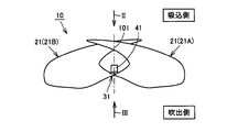
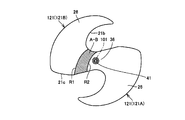
- FIG. 1 is a side view showing a two-blade propeller fan according to Embodiment 1 of the present invention.
- FIG. 2 is a plan view showing the propeller fan viewed from the direction (suction side) indicated by the arrow II in FIG.
- FIG. 3 is a plan view showing the propeller fan viewed from the direction indicated by arrow III in FIG.
- FIG. 4 is a perspective view of the propeller fan in FIG. 1 viewed from the suction side.
- propeller fan 10 in the present embodiment is a two-blade propeller fan, and is integrally molded with a synthetic resin such as glass fiber-containing AS (acrylonitrile-styrene) resin. Yes.
- the propeller fan 10 includes a blade 21A and a blade 21B (hereinafter referred to as a blade 21 unless otherwise specified) and a connecting portion 31 that connects (connects) the blade 21A and the blade 21B to each other.
- the propeller fan 10 rotates around a central axis 101 which is a virtual axis, and blows air from the suction side to the blowout side in FIG.
- a minimum virtual circle 102 is drawn so as to separate the blades 21A and 21B from each other in the circumferential direction of the central shaft 101.
- the connecting portion 31 is defined inside the virtual circle 102, and the wings 21A and 21B are defined outside the virtual circle 102.
- the blades 21 ⁇ / b> A and 21 ⁇ / b> B are arranged at equal intervals in the rotational axis of the propeller fan 10, that is, in the circumferential direction of the central shaft 101.
- the wing 21A and the wing 21B are formed in the same shape, and are formed such that when one wing is rotated around the central axis 101 toward the other wing, the shapes of the two wings coincide.
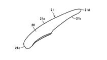
- the blade 21 includes a front edge portion 21 b positioned on the propeller fan 10 in the rotation direction side, a rear edge portion 21 c positioned on the opposite side of the rotation direction, and a peripheral edge portion 21 a positioned on the outermost side with respect to the central shaft 101. And have.
- the peripheral edge portion 21a is formed to extend in an arc shape having a diameter D around the central axis 101.
- the peripheral edge portion 21a is formed such that one end extending in an arc shape continues to the rear edge portion 21c.
- the blade 21 further has a blade tip edge portion 21d.
- the blade tip edge portion 21d is formed so as to connect between the peripheral edge portion 21a and the front edge portion 21b.
- the blade tip edge portion 21d has a sickle-like shape.
- the peripheral edge portion 21a is formed so that the other end extending in an arc shape is connected to the rear edge portion 21c via the blade tip edge portion 21d.
- the blade tip edge 21d is provided at the tip of the propeller fan 10 in the most rotational direction in the blade 21 in which the blade tip edge 21d is formed.
- the outer shape of the blade 21 is constituted by a front edge portion 21b, a blade tip edge portion 21d, a peripheral edge portion 21a, and a rear edge portion 21c.
- the blade 21 is formed with a blade surface 26 that blows air as the propeller fan 10 rotates (sends air from the suction side to the discharge side).
- the blade surface 26 is formed on each side facing the suction side and the blowout side.
- the blade surface 26 is formed in a region surrounded by the front edge portion 21b, the blade tip edge portion 21d, the peripheral edge portion 21a, and the rear edge portion 21c.
- the blade surface 26 is formed on the entire surface surrounded by the front edge portion 21b, the blade tip edge portion 21d, the peripheral edge portion 21a, and the rear edge portion 21c.
- the blade surfaces 26 of the blades 21A and 21B are formed by curved surfaces that are inclined from the suction side to the discharge side in the circumferential direction from the front edge portion 21b to the rear edge portion 21c.
- the blade surface 26 is composed of a pressure surface 26q and a suction surface 26p disposed on the back side of the pressure surface 26q.
- the positive pressure surface 26q is formed on the side facing the blowing side of the blade surface 26, and the negative pressure surface 26p is formed on the side facing the suction side of the blade surface 26.
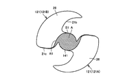
- the root portion of the wing 21 ⁇ / b> A and the root portion of the wing 21 ⁇ / b> B arranged on the outer periphery of the virtual circle 102 are connected to each other by a connecting portion 31 arranged around the center axis 101.
- the connecting portion 31 has a blade surface 36 on each side facing the suction side and the blowout side, and is formed in an airfoil shape.
- the blade surface 36 is formed continuously from the blade surface 26 of the blade 21A and the blade surface 26 of the blade 21B.
- the blade surface 26 of the blade 21 ⁇ / b> A and the blade surface 26 of the blade 21 ⁇ / b> B are continuously formed via the blade surface 36.
- the leading edge 21b of the wing 21A and the trailing edge 21c of the wing 21B face each other in the direction connecting the wing 21A and the wing 21B, and the leading edge 21b of the wing 21B and the trailing edge of the wing 21A.
- the inclination direction of the blade surface 36 on the blade 21A side and the inclination direction of the blade surface 36 on the blade 21B side are twisted with the central axis 101 interposed therebetween.
- the inclination of the blade surface decreases, and the blade surface 36 on the blade 21A side and the blade surface 36 on the blade 21B side eventually become the central axis.
- a smooth connection is made on a line passing through 101. That is, the blades 21A and 21B and the connecting portion 31 form a blade surface 26 and a blade surface 36, which are formed integrally and continuously tangent, respectively.
- a region connecting the root portion of the blade 21A and the root portion of the blade 21B in the connecting portion 31 is formed in a blade surface shape that blows air with rotation.
- the leading edge 21b of the wing 21A and the trailing edge 21c of the wing 21B are connected through the connecting portion 31, and the leading edge 21b of the wing 21B and the rear of the wing 21A are connected.
- the edge portion 21 c is connected through the connecting portion 31.
- the virtual circle 102 is in contact with the connection portion between the front edge portion 21b of the blade 21A and the rear edge portion 21c of the blade 21B, and is in contact with the connection portion between the front edge portion 21b of the blade 21B and the rear edge portion 21c of the blade 21A. It is drawn.
- the connecting portion 31 extends from the suction side in the airflow delivery direction to the blowout side from the root portion on the front edge portion 21b side of the blade 21A toward the root portion on the rear edge portion 21c side of the blade 21B, and extends in front of the blade 21B. It is formed so as to extend from the suction side in the airflow delivery direction to the blowout side as it goes from the root part on the edge part 21b side to the root part on the rear edge part 21c side of the blade 21A.
- the connecting part 31 is formed so as to have a function of sending air from the suction side in the airflow sending direction of the propeller fan 10 to the blowing side.
- the blades 21A and 21B and the connecting portion 31 have a thin shape and are integrally molded.
- a single two-blade extending around the center axis 101 to the outer periphery thereof is integrally molded by blade 21A, blade 21B, and connecting portion 31.
- Propeller fan 10 is integrally formed including blade 21A and blade 21B, and a connecting portion 31 connecting the root portion of blade 21A and the root portion of blade 21B.
- the propeller fan 10 has a boss hub portion 41 as a rotating shaft portion.
- the boss hub portion 41 is a portion that connects the propeller fan 10 to an output shaft of a motor (not shown) that is a drive source thereof.
- the boss hub portion 41 has a cylindrical shape and is connected to the connecting portion 31 at a position overlapping the central axis 101.
- the boss hub portion 41 is formed to extend in the axial direction of the central shaft 101 from the blade surface 36 on the suction side.
- the boss hub portion 41 which is a member for rotationally driving the blade 21A and the blade 21B with the region connecting the root portion of the blade 21A and the root portion of the blade 21B as a rotation center, Propeller fan 10 is provided integrally.
- the shape of the boss hub portion 41 is not limited to a cylindrical shape, and can be changed as appropriate according to the connection structure with respect to the output shaft of the motor.
- the boss hub portion 41 may be formed to extend from the blowing side blade surface 36 or may be formed to extend from the suction side and blowing side blade surface 36.
- the connecting portion 31 is formed so as to extend from the outer peripheral surface of the boss hub portion 41 to the outer peripheral side.
- the connecting part 31 is the minimum of the outer edge of the connecting part 31 on the virtual line Z that intersects the central axis 101 at a right angle from the central axis 101.
- the outer edge of the boss hub 41 on the imaginary line Z is formed such that the distance L2 from the central axis 101 is smaller than the distance L1 (see FIG. 2).
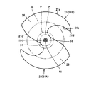
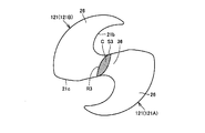
- FIG. 5 is a plan view showing an example of the propeller fan in FIG. 6 is a perspective view showing a cross-sectional shape when the propeller fan in FIG. 5 is cut at a position indicated by a two-dot chain line X.
- FIG. FIG. 7 is a perspective view showing a cross-sectional shape when the propeller fan in FIG. 5 is cut at a position indicated by a two-dot chain line Y.
- FIG. FIG. 8 is a perspective view showing a cross-sectional shape when the propeller fan in FIG. 5 is cut at a position indicated by a two-dot chain line Z.
- FIG. 6 and 7 show a cross section of the blade 21, and FIG. 8 shows a cross section of the connecting portion 31.
- the blade 21 has a circumferential cross-sectional thickness connecting the leading edge portion 21b and the trailing edge portion 21c from the vicinity of the blade center to the leading edge portion 21b and the trailing edge portion 21c. Each of them is thinner as it goes, and is formed into an airfoil shape having a maximum thickness at a position closer to the leading edge 21b side than the blade center.
- the connecting portion 31 is formed in an airfoil shape similar to the wing 21 described above.
- propeller fan 10 in the present embodiment is formed to have an airfoil cross-sectional shape at any cross-sectional position from peripheral edge 21 a of blade 21 toward central axis 101.
- the propeller fan 10 integrally molded by a synthetic resin
- the propeller fan in this invention is not restricted to resin.
- the propeller fan 10 may be formed by twisting a single sheet metal, or the propeller fan 10 may be formed of an integral thin-walled object formed with a curved surface. In these cases, a separately molded boss hub portion 41 may be joined to the rotation center of the propeller fan 10.
- the peripheral edge portion 21a and the rear edge portion 21c are continuous at an intersection 21e.
- the intersection 21e exists at a position where the end of the peripheral edge 21a having a diameter D and drawing a circular arc intersects with the rear edge 21c connected to the end.
- the intersection 21e on the wing 21A and the intersection 21e on the wing 21B exist at the same height in the axial direction of the central axis 101.
- a virtual plane 210 including the blade tip edge 21d connecting the front edge 21b and the peripheral edge 21a and the central axis 101 is defined.
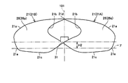
- FIG. 9 is another side view showing the propeller fan in FIG.
- FIG. 9 shows the propeller fan 10 viewed from the direction indicated by the arrow IX parallel to the plane 210 in FIG.
- a plane ⁇ including the intersection 21e of the wing 21A and the wing 21B and orthogonal to the central axis 101 is defined.
- the front edge portion 21 b of the blade 21 ⁇ / b> A and the rear edge portion 21 c of the blade 21 ⁇ / b> B are connected through the connecting portion 31.
- a connecting portion between the front edge portion 21b of the blade 21A and the rear edge portion 21c of the blade 21B crosses the central axis 101 from the front edge portion 21b of the blade 21A toward the rear edge portion 21c of the blade 21B. It is formed to extend from the suction side in the delivery direction to the blowout side.
- propeller fan 10 in the present embodiment satisfies the relationship of 0.028 ⁇ H / D ⁇ 0.056.
- diameter d of virtual circle 102 is the peripheral portion of blade 21.
- the value is set to 0.14 times the diameter D of 21a. That is, propeller fan 10 in the present embodiment is formed to satisfy the relationship of 0.14 ⁇ d / D.
- the relational expression between the diameter d of the virtual circle 102 and the diameter D of the blade 21 is not an essential configuration.
- a propeller fan that satisfies the relationship of 0.14 ⁇ d / D may be configured not to satisfy the relationship of 0.028 ⁇ H / D ⁇ 0.056.
- an airfoil connecting portion 31 that connects the blades 21A and 21B is provided.
- it can be effectively used as a blade having a cross-sectional shape of an airfoil and a large angle of attack even in a rotation center that has not been sufficiently used as a boss hub.
- the ventilation capability in the vicinity of the central portion where the peripheral speed is slow compared to the outer peripheral side can be significantly increased, and the ventilation performance of the entire fan can be greatly improved.
- the air volume can be increased at the same rotational speed. Furthermore, the mass of the propeller fan can be reduced by replacing most of the large boss hub portion that has conventionally existed in the rotation center portion with the connecting portion 31 having a wing-shaped cross-sectional shape. As a result, the load on the driving motor is reduced, and power consumption can be reduced with the same air volume.
- 10 to 13 are diagrams for explaining the mechanism of the propeller fan in FIG.
- FIG. 10 shows a propeller fan for comparison.
- boss hub portion 141 is provided at the center of rotation, and blades 121 (121A, 121A, 121B).
- the shape of the wing 121 is almost the same as the wing 21 in FIG.
- the propeller fan 10 in the present embodiment has a very small boss hub portion 41 and works as a blade to a position closer to the center than the propeller fan 110 for comparison.
- Wind flows into the blade surface 36 from the front edge portion 21b (S2 in FIG. 12) in the vicinity of the boundary with the connecting portion 31. Thereafter, the streamline extends slightly outside the concentric circles and draws R2 in FIG.
- the hatched portion (area B) inside the R2 cannot perform the work of the blower that sends the wind.
- FIG. 13 shows an area difference (A ⁇ B) in a region where the work of the blower that sends the winds of both cannot be performed.
- the propeller fan 10 in the present embodiment increases the lift generated in the fan by the area difference (A ⁇ B). It is known that the wind is blown by a reaction force generated by the reaction of the lift force. When the lift force is large, the reaction force is increased correspondingly, and the blowing ability is increased.
- the air blowing capacity can be improved by the connecting portion 31 arranged at the rotation center.
- Propeller fan 10 in the present embodiment has a relationship of 0.028 ⁇ H / D ⁇ 0.056 (D: diameter of peripheral portion 21a of blade 21; H: plane ⁇ on the line of central axis 101; blade 21A The distance between the front edge portion 21b and the connecting portion of the rear edge portion 21c of the blade 21B.
- FIG. 14 is a side view showing a propeller fan which is a first comparative example with respect to the propeller fan in FIG.
- FIG. 15 is a side view showing a propeller fan that is a second comparative example with respect to the propeller fan in FIG. 9.
- the distance between the plane ⁇ and the connecting portion of the leading edge 21b of the blade 21A and the trailing edge 21c of the blade 21B is H1, and the propeller satisfies the relationship of H1 / D ⁇ 0.028. Fans are shown.
- the distance between the plane ⁇ and the connecting portion of the leading edge 21b of the blade 21A and the trailing edge 21c of the blade 21B is H2, and the propeller satisfies the relationship of H2 / D> 0.056. Fans are shown.
- the connecting portion between the front edge portion 21b of the blade 21A and the rear edge portion 21c of the blade 21B Extends at a small angle with respect to a plane orthogonal to the central axis 101. In this case, the air flowing in from the front edge portion 21b of the blade 21A and flowing out from the rear edge portion 21c of the blade 21B cannot be sent out strongly in the axial direction of the central shaft 101 in the vicinity of the rotation center. Damaged.
- 16 and 17 are diagrams for explaining the mechanism of the propeller fan in FIG.
- propeller fan 10 in the present embodiment satisfying the relationship of 0.028 ⁇ H / D has blade 21A as compared with the propeller fan of the first comparative example.
- a connecting portion between the leading edge portion 21b and the trailing edge portion 21c of the blade 21B is inclined at a large angle with respect to a plane orthogonal to the central axis 101, and is warped in the axial direction of the central axis 101.
- FIG. 16 shows an area difference (BC) in a region where the work of the blower sending the wind cannot be performed in comparison with the propeller fan in FIG.
- the connecting portion of the front edge portion 21b of the blade 21A and the rear edge portion 21c of the blade 21B is in a state of being inclined at a larger angle with respect to a plane orthogonal to the central axis 101.
- air easily flows into the pressure surface 26q near the connection portion between the front edge portion 21b of the blade 21A and the rear edge portion 21c of the blade 21B, while air flow separation occurs on the suction surface 26p side. May occur.
- propeller fan 310 in the present embodiment that satisfies the relationship of H / D ⁇ 0.056, the inclination of blade 21 at the connection portion of front edge portion 21b of blade 21A and rear edge portion 21c of blade 21B is the same. Is prevented from becoming too large, and peeling on the suction surface 26p side is prevented.
- the propeller fan 10 according to the present embodiment satisfying the relationship of 0.028 ⁇ H / D ⁇ 0.056 can realize an excellent blowing capacity.
- the propeller fan 10 in the embodiment it is possible to suppress an increase in power consumption of the motor even if the air volume is increased. (4) By reducing the weight, the material can be reduced and the power consumption of the motor can be further reduced. (If the weight of the fan is large, the bearing loss of the motor shaft and the like increase, and extra power consumption is required. On the other hand, according to the propeller fan 10 in the present embodiment, the fan is significantly reduced in weight. As a result, the bearing loss of the motor shaft can be reduced, so that the power consumption of the motor can be reduced. As a result, according to propeller fan 10 in the first embodiment of the present invention, it is possible to realize a propeller fan that greatly contributes to global environment conservation in terms of energy saving and resource saving design.
- the diameter d of the virtual circle 102 is set to a value not less than 0.14 times the diameter D of the peripheral edge 21 a of the blade 21. Accordingly, the size of the connecting portion 31 that plays a role of connecting the root portion of the blade 21A and the root portion of the blade 21B is prevented from becoming too small with respect to the outer peripheral dimension of the blade. As a result, the strength of the propeller fan 10 can be sufficiently ensured.
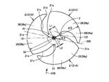
- FIG. 18 is a side view showing the three-blade propeller fan according to Embodiment 1 of the present invention.
- FIG. 19 is a plan view showing the propeller fan viewed from the direction (suction side) indicated by the arrow XIX in FIG.
- FIG. 20 is a plan view showing the propeller fan as seen from the direction (outlet side) indicated by the arrow XX in FIG.
- FIG. 21 is a perspective view of the propeller fan in FIG. 18 viewed from the suction side.
- propeller fan 50 in the present embodiment is a three-blade propeller fan.
- Propeller fan 50 is spaced apart in the circumferential direction, and blade 21A, blade 21B and blade 21C (hereinafter referred to as blade 21 unless otherwise specified) that blow air as it rotates about central shaft 101.
- blade 21A, blade 21B, and blade 21C (hereinafter referred to as blade 21 unless otherwise specified) that blow air as it rotates about central shaft 101.
- a connecting portion 31 that connects the blade 21A, the blade 21B, and the blade 21C.
- a minimum virtual circle 102 is drawn that separates the blades 21 ⁇ / b> A, 21 ⁇ / b> B, and 21 ⁇ / b> C in the circumferential direction of the central shaft 101.
- the connecting portion 31 is defined inside the virtual circle 102, and the wing 21A, the wing 21B, and the wing 21C are defined outside the virtual circle 102.
- the blades 21A, 21B, and 21C are arranged at equal intervals in the circumferential direction of the rotation axis of the propeller fan 50, that is, the central shaft 101.
- the wing 21A, the wing 21B, and the wing 21C are formed in the same shape.
- the blade 21B is arranged adjacent to the blade 21A in the rotation direction of the propeller fan 50, and the blade 21C is arranged adjacent to the blade 21B in the rotation direction of the propeller fan 50.
- the root portion of the wing 21A, the root portion of the wing 21B, and the root portion of the wing 21C arranged on the outer periphery of the virtual circle 102 are connected to each other by a connecting portion 31 arranged around the axis of the central axis 101.
- a single three-blade extending around the central axis 101 around the central shaft 101 is integrated by the blade 21A, the blade 21B, the blade 21C, and the connecting portion 31. Is molded.
- the leading edge 21b of the wing 21A and the trailing edge 21c of the wing 21B are connected through the connecting portion 31, and the leading edge 21b of the wing 21B and the rear of the wing 21C are connected.
- the edge portion 21c is connected through the connecting portion 31, and the front edge portion 21b of the blade 21C and the rear edge portion 21c of the blade 21A are connected through the connecting portion 31.
- the virtual circle 102 is in contact with a connection portion between the front edge portion 21b of the wing 21A and the rear edge portion 21c of the wing 21B, and is in contact with a connection portion between the front edge portion 21b of the wing 21B and the rear edge portion 21c of the wing 21C. It is drawn so as to be in contact with the connecting portion between the front edge portion 21b of 21C and the rear edge portion 21c of the blade 21A.
- the propeller fan 50 has a boss hub portion 41 as a central shaft portion.
- the connecting portion 31 is formed so as to extend from the outer peripheral surface of the boss hub portion 41 to the outer peripheral side.
- the connecting portion 31 is smaller than the minimum length L1 of the connecting portion 31 from the central axis 101 on the imaginary line Z passing through the central axis 101 when the propeller fan 50 is viewed from the axial direction of the central axis 101.
- the length L2 of the boss hub 41 from the central axis 101 on the virtual line Z is formed to be smaller (see FIG. 19).
- peripheral edge portion 21a and trailing edge portion 21c are connected at intersection 21e. Yes.
- the intersection 21e on the wing 21A, the intersection 21e on the wing 21B, and the intersection 21e on the wing 21C exist at the same height in the axial direction of the central axis 101.
- a virtual plane 220 including a blade tip edge portion 21d connecting the leading edge portion 21b and the peripheral edge portion 21a in the blade 21C and the central axis 101 is defined.
- FIG. 22 is another side view showing the propeller fan in FIG. 22 shows the propeller fan 50 as viewed from the direction indicated by the arrow XXII orthogonal to the plane 220 in FIG.
- a plane ⁇ that includes the intersection 21e of the wing 21A, wing 21B, and wing 21C and is orthogonal to the central axis 101 is defined.
- the front edge portion 21 b of the blade 21 ⁇ / b> A and the rear edge portion 21 c of the blade 21 ⁇ / b> B are connected through the connecting portion 31.
- propeller fan 50 in the present embodiment satisfies the relationship of 0.028 ⁇ H / D ⁇ 0.056.
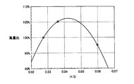
- FIG. 23 is a graph showing the relationship between H / D and the air volume of the propeller fan in FIG.
- H distance between plane ⁇ and the connecting portion of leading edge 21b of blade 21A and trailing edge 21c of blade 21B
- D peripheral edge of blade 21
- Plural types of propeller fans having different values of the diameter D) of 21a were prepared and rotated at a constant rotational speed.
- the air volume in each propeller fan was measured, and the measurement results are summarized in the graph of FIG.
- the diameter D was 460 mm and the rotation speed was 1000 rpm.
- FIG. 24 is a graph showing the relationship between d / D and maximum stress of the propeller fan in FIG.
- the maximum stress of the propeller fan is changed as d (diameter of virtual circle 102) / D (diameter D of peripheral edge 21a of blade 21) changes.
- the change was measured by simulation, and the results are summarized in the graph shown in FIG.
- the propeller fan was rotated about the central axis 101, and the stress acting on the entire propeller fan due to the centrifugal load was obtained.
- the rotation speed was constant at 1000 rpm, and the largest stress among stress values acting on the entire propeller fan was defined as the maximum stress.
- the maximum stress of the propeller fan 10 gradually increased as the d / D value decreased, that is, as the ratio of the size of the connecting portion 31 to the outer periphery of the blade decreased.
- the value of d / D is in a range smaller than 0.14, the maximum stress is remarkably increased, and the strength of the propeller fan 10 is remarkably lowered.
- the strength of the propeller fan 10 could be secured in the range of 0.14 ⁇ d / D.
- FIG. 25 is a cross-sectional view showing a molding die used for manufacturing a propeller fan.
- the molding die 61 includes a fixed side die 62 and a movable side die 63.
- the fixed side mold 62 and the movable side mold 63 define a cavity that is substantially the same shape as the propeller fan and into which a fluid resin is injected.
- the molding die 61 may be provided with a heater (not shown) for enhancing the fluidity of the resin injected into the cavity.
- a heater for enhancing the fluidity of the resin injected into the cavity.
- the installation of such a heater is particularly effective when, for example, a synthetic resin with increased strength such as an AS resin containing glass fiber is used.
- the pressure side surface of the propeller fan is formed by the fixed side die 62 and the suction side surface is formed by the movable side die 63.
- the suction surface side surface of the propeller fan may be formed by the stationary mold 62, and the pressure surface side surface of the propeller fan may be formed by the movable mold 63.
- Some propeller fans use metal as the material and are integrally formed by drawing by press working. In these moldings, it is difficult to squeeze with a thick metal plate, and the mass becomes heavy, so that a thin metal plate is generally used. In this case, it is difficult to maintain strength (rigidity) with a large propeller fan.
- a part that uses a part called a spider formed of a metal plate thicker than the wing part and fixes the wing part to the rotating shaft, but there is a problem that the mass becomes heavy and the fan balance is also deteriorated.
- a thin metal plate having a certain thickness is used, there is a problem in that the cross-sectional shape of the wing portion cannot be a wing shape.
- an outdoor unit of an air conditioner will be described as an example of a fluid feeder having the propeller fan 10 in the first embodiment.
- FIG. 26 is a diagram showing an outdoor unit of an air conditioner using a propeller fan.
- the outdoor unit 75 of the air conditioner includes a blower 73 having the propeller fan 10 and the drive motor 72 in the first embodiment. Fluid is sent out by the blower 73.
- An outdoor heat exchanger 74 is provided in the outdoor unit 75, and heat exchange is efficiently performed by the blower 73.
- the blower 73 is installed in the outdoor unit 75 by a motor angle 76.
- the outdoor unit 75 since the outdoor unit 75 has the propeller fan 10 described in the first embodiment, the generation of noise is suppressed and the operation sound is quiet.
- the outdoor unit 75 can reduce energy consumption.
- the same effect is acquired also when the propeller fan 50 demonstrated in Embodiment 1 is used.
- an example of an air conditioner outdoor unit has been described as an example of a fluid feeder, but in addition to this, for example, an air purifier, a humidifier, a fan, a fan heater, and a cooling device The same effect can be obtained by applying this propeller fan to a device for delivering a fluid such as a ventilation device.
- the present invention is mainly applied to household electric appliances having a blowing function such as an air purifier and an air conditioner.
Landscapes
- Engineering & Computer Science (AREA)
- Mechanical Engineering (AREA)
- General Engineering & Computer Science (AREA)
- Structures Of Non-Positive Displacement Pumps (AREA)
Abstract
Description
[2枚翼のプロペラファンの構造の説明]
図1は、この発明の実施の形態1における2枚翼のプロペラファンを示す側面図である。図2は、図1中の矢印IIに示す方向(吸込側)から見たプロペラファンを示す平面図である。図3は、図1中の矢印IIIに示す方向(吹出側)から見たプロペラファンを示す平面図である。図4は、図1中のプロペラファンを吸込側から見た斜視図である。
続いて、本実施の形態におけるプロペラファン10によって奏される作用、効果について説明する。
(2)圧力流量特性を向上できるため、ファン性能を向上できる。(近年、たとえば、空気調和機においては、省エネルギー性を向上させるために熱交換器の能力増加に伴い圧力損失が増大する傾向にある。熱交換器の圧力損失が増大すると、風量が低下する(トレードオフの関係)ため、熱交換器の能力増加の効果を十分に得ることができないという課題があった。これに対して、本実施の形態におけるプロペラファン10によれば、圧力流量特性を向上できるため、圧力損失の大きい熱交換器に対しても、風量の低下を抑制でき、その結果、熱交換器の能力増加の効果を十分に得ることができる。)
(3)ファン効率を向上でき、消費電力を低減できる。(近年、たとえば、空気調和機においては、省エネルギー性を向上させるために風量を増加する傾向にある。このため、モータの消費電力が増大するといった問題があった。これに対して、本実施の形態におけるプロペラファン10によれば、風量を増加してもモータの消費電力の増大を抑制できる。風量を増加しない場合には、効率が向上しているため、モータの消費電力を低減できる。)
(4)軽量化により、材料を削減できるとともに、モータの消費電力をさらに低減できる。(ファンの重量が大きいと、モータシャフトのベアリング損失等が増大し、余分な消費電力を必要とする。これに対して、本実施の形態におけるプロペラファン10によれば、ファンを大幅に軽量化でき、その結果、モータシャフトのベアリング損失等を減少できるため、モータの消費電力を低減できる。)
この結果、この発明の実施の形態1におけるプロペラファン10によれば、地球環境保全に対し、省エネルギー性、省資源設計の面で、大きく貢献するプロペラファンを実現することができる。
続いて、図1中のプロペラファン10の構造を適用した3枚翼のプロペラファンの構造について説明する。なお、図1中のプロペラファン10と比較して重複する構造については説明を繰り返さない。
続いて、本実施の形態におけるプロペラファン10,50によって奏される作用、効果を確認するために行なった実施例について説明する。
図23を参照して、本実施例では、H(平面γと、翼21Aの前縁部21bおよび翼21Bの後縁部21cの接続部分との間の距離)/D(翼21の周縁部21aの直径D)の値が異なる複数種類のプロペラファンを準備し、一定の回転数で回転させた。各プロペラファンにおける風量を測定し、その測定結果を図23中のグラフにまとめた。本実施例では、直径Dを460mmとし、回転数を1000rpmとした。
図24を参照して、本実施例では、d(仮想円102の直径)/D(翼21の周縁部21aの直径D)が変化するのに伴って、プロペラファンの最大応力がどのように変化するかをシミュレーションにより測定し、その結果を図24中に示すグラフにまとめた。シミュレーションは、中心軸101を中心にプロペラファンを回転させ、遠心力荷重によりプロペラファン全体に作用する応力を求めた。回転数は、1000rpmで一定とし、プロペラファン全体に作用する応力値の中で最も大きい応力を最大応力とした。
本実施の形態では、まず、実施の形態1における各種プロペラファンを樹脂を用いて成型するための成型用金型の構造について説明する。
Claims (12)
- 2枚翼のプロペラファンであって、
周方向に離間して設けられ、仮想の中心軸(101)を中心に回転するのに伴って送風を行ない、2枚翼をなす第1翼(21A)および第2翼(21B)と、
プロペラファンを前記中心軸(101)の軸方向から見て、前記第1翼(21A)および前記第2翼(21B)を周方向に離間させるような最小の仮想円(102)を描いた場合に、その仮想円(102)の内側に配置され、前記第1翼(21A)および前記第2翼(21B)を連接する連接部(31)とを備え、
前記第1翼(21A)および前記第2翼(21B)の各翼は、前記中心軸(101)を中心に、直径Dを有して円弧状に延びる周縁部(21a)と、回転方向の側に配置される前縁部(21b)と、回転方向の反対側に配置され、前記周縁部(21a)に連なる後縁部(21c)と、前記前縁部(21b)と前記周縁部(21a)とを接続し、回転方向に向けて突出する翼先端縁部(21d)とを有し、
前記第1翼(21A)の前記前縁部(21b)と前記第2翼(21B)の前記後縁部(21c)とが、前記連接部(31)を通じて接続され、
前記第1翼(21A)および前記第2翼(21B)の、前記後縁部(21c)および前記周縁部(21a)の各交点(21e)を含み、前記中心軸(101)に直交する平面をγと規定し、
プロペラファンを、前記第1翼(21A)および前記第2翼(21B)の前記翼先端縁部(21d)と、前記中心軸(101)とを含む平面(210)に平行な方向から見た場合に、前記中心軸(101)の線上における、前記平面γと、前記第1翼(21A)の前記前縁部(21b)および前記第2翼(21B)の前記後縁部(21c)の接続部分との間の距離Hは、0.028≦H/D≦0.056の関係を満たす、プロペラファン。 - 前記連接部(31)は、前記第1翼(21A)と前記第2翼(21B)との間で延在し、前記第1翼(21A)の根元部および前記第2翼(21B)の根元部を接続する領域に、回転に伴って送風を行なうための翼面状の表面(36)を有する、請求の範囲1に記載のプロペラファン。
- 前記仮想円(102)の直径dは、0.14≦d/Dの関係を満たす、請求の範囲1に記載のプロペラファン。
- 樹脂により成型される、請求の範囲1に記載のプロペラファン。
- 請求の範囲4に記載のプロペラファンを樹脂により成型するために用いられる、成型用金型。
- 請求の範囲1に記載のプロペラファンを備える、流体送り装置。
- 3枚翼のプロペラファンであって、
周方向に離間して設けられ、仮想の中心軸(101)を中心に回転するのに伴って送風を行ない、3枚翼をなす第1翼(21A)、第2翼(21B)および第3翼(21C)と、
プロペラファンを前記中心軸(101)の軸方向から見て、前記第1翼(21A)、前記第2翼(21B)および前記第3翼(21C)を周方向に離間させるような最小の仮想円(102)を描いた場合に、その仮想円(102)の内側に配置され、前記第1翼(21A)、前記第2翼(21B)および前記第3翼(21C)を連接する連接部(31)とを備え、
前記第1翼(21A)、前記第2翼(21B)および前記第3翼(21C)の各翼は、前記中心軸(101)を中心に、直径Dを有して円弧状に延びる周縁部(21a)と、回転方向の側に配置される前縁部(21b)と、回転方向の反対側に配置され、前記周縁部(21a)に連なる後縁部(21c)と、前記前縁部(21b)と前記周縁部(21a)とを接続し、回転方向に向けて突出する翼先端縁部(21d)とを有し、
前記第2翼(21B)は、前記第1翼(21A)に対して回転方向の側に隣接して配置され、前記第3翼(21C)は、前記第2翼(21B)に対して回転方向の側に隣接して配置され、
前記第1翼(21A)の前記前縁部(21b)と、前記第2翼(21B)の前記後縁部(21c)とが、前記連接部(31)を通じて接続され、
前記第1翼(21A)、前記第2翼(21B)および前記第3翼(21C)の、前記後縁部(21c)および前記周縁部(21a)の各交点(21e)を含み、前記中心軸(101)に直交する平面をγと規定し、
プロペラファンを、前記第3翼(21C)の前記翼先端縁部(21d)と、前記中心軸(101)とを含む平面(220)に直角な方向から見た場合に、前記中心軸(101)の線上における、前記平面γと、前記第1翼(21A)の前記前縁部(21b)および前記第2翼(21B)の前記後縁部(21c)の接続部分との間の距離Hは、0.028≦H/D≦0.056の関係を満たす、プロペラファン。 - 前記連接部(31)は、前記第1翼(21A)、前記第2翼(21B)および前記第3翼(21C)のうちの隣接する翼間で延在し、隣接する翼の根元部同士を接続する領域に、回転に伴って送風を行なうための翼面状の表面(36)を有する、請求の範囲7に記載のプロペラファン。
- 前記仮想円(102)の直径dは、0.14≦d/Dの関係を満たす、請求の範囲7に記載のプロペラファン。
- 樹脂により成型される、請求の範囲7に記載のプロペラファン。
- 請求の範囲10に記載のプロペラファンを樹脂により成型するために用いられる、成型用金型。
- 請求の範囲7に記載のプロペラファンを備える、流体送り装置。
Priority Applications (4)
| Application Number | Priority Date | Filing Date | Title |
|---|---|---|---|
| CN201080040194.8A CN102483073B (zh) | 2009-09-11 | 2010-09-07 | 螺旋桨式风扇、成型用模具和流体输送装置 |
| EP10815345.3A EP2476912B1 (en) | 2009-09-11 | 2010-09-07 | Propeller fan, molding die, and fluid feed device |
| KR1020127008985A KR101348012B1 (ko) | 2009-09-11 | 2010-09-07 | 프로펠러 팬, 성형용 금형 및 유체 이송 장치 |
| US13/395,194 US8926286B2 (en) | 2009-09-11 | 2010-09-07 | Propeller fan, molding die, and fluid feeder |
Applications Claiming Priority (2)
| Application Number | Priority Date | Filing Date | Title |
|---|---|---|---|
| JP2009-210295 | 2009-09-11 | ||
| JP2009210295A JP4798640B2 (ja) | 2009-09-11 | 2009-09-11 | プロペラファン、成型用金型および流体送り装置 |
Publications (1)
| Publication Number | Publication Date |
|---|---|
| WO2011030748A1 true WO2011030748A1 (ja) | 2011-03-17 |
Family
ID=43732420
Family Applications (1)
| Application Number | Title | Priority Date | Filing Date |
|---|---|---|---|
| PCT/JP2010/065301 Ceased WO2011030748A1 (ja) | 2009-09-11 | 2010-09-07 | プロペラファン、成型用金型および流体送り装置 |
Country Status (6)
| Country | Link |
|---|---|
| US (1) | US8926286B2 (ja) |
| EP (1) | EP2476912B1 (ja) |
| JP (1) | JP4798640B2 (ja) |
| KR (1) | KR101348012B1 (ja) |
| CN (1) | CN102483073B (ja) |
| WO (1) | WO2011030748A1 (ja) |
Cited By (1)
| Publication number | Priority date | Publication date | Assignee | Title |
|---|---|---|---|---|
| EP2642130B1 (en) * | 2012-03-22 | 2019-04-17 | Elica S.p.A. | Impeller for axially conveying fluids, particularly for refrigeration systems |
Families Citing this family (16)
| Publication number | Priority date | Publication date | Assignee | Title |
|---|---|---|---|---|
| CN104145120B (zh) | 2012-04-10 | 2017-09-01 | 夏普株式会社 | 电风扇用螺旋桨式风扇和具备其的电风扇以及电风扇用螺旋桨式风扇的成形用模具 |
| MY166098A (en) | 2012-04-10 | 2018-05-24 | Sharp Kk | Propeller fan, fluid feeder, and molding die |
| CN104088812B (zh) * | 2013-04-01 | 2017-05-17 | 苏州三星电子有限公司 | 一种轴流风扇 |
| AU353966S (en) * | 2013-08-05 | 2014-02-26 | Mitsubishi Electric Corp | Propeller fan |
| AU353962S (en) * | 2013-08-05 | 2014-02-26 | Mitsubishi Electric Corp | Propeller fan |
| JP1530002S (ja) * | 2014-08-11 | 2015-08-03 | ||
| CN107178512A (zh) * | 2017-07-27 | 2017-09-19 | 张兴军 | 螺旋桨式风扇及成型用模具 |
| EP3636337B1 (en) * | 2018-10-12 | 2023-08-16 | Xylem Europe GmbH | Propeller for a digestion tank mixer |
| USD972119S1 (en) * | 2018-11-28 | 2022-12-06 | Ebm-Papst Mulfingen Gmbh & Co. Kg | Fan |
| USD972706S1 (en) * | 2019-02-28 | 2022-12-13 | Ebm-Papst St. Georgen Gmbh & Co. Kg | Ventilating fan |
| USD971398S1 (en) * | 2019-03-04 | 2022-11-29 | Ebm-Papst Mulfingen Gmbh & Co. Kg | Fan wheel of an axial fan |
| USD980409S1 (en) * | 2019-03-07 | 2023-03-07 | Ziehl-Abegg Se | Fan wheel |
| USD972707S1 (en) * | 2019-04-29 | 2022-12-13 | Ebm-Papst Mulfingen Gmbh & Co. Kg | Ventilating fan |
| USD980965S1 (en) * | 2019-05-07 | 2023-03-14 | Carrier Corporation | Leading edge of a fan blade |
| CN110701103B (zh) * | 2019-11-14 | 2020-11-10 | 广东三奇实业发展有限公司 | 一种节能环保磁悬浮鼓风机组装机构 |
| CN115405538A (zh) * | 2021-05-28 | 2022-11-29 | 冷王公司 | 高效轴流式风扇 |
Citations (9)
| Publication number | Priority date | Publication date | Assignee | Title |
|---|---|---|---|---|
| JPS6383496U (ja) * | 1986-11-19 | 1988-06-01 | ||
| JPS64397A (en) | 1987-03-13 | 1989-01-05 | Nippon Denso Co Ltd | Blower fan |
| JPH0388999A (ja) | 1989-09-01 | 1991-04-15 | Hitachi Ltd | 軸流フアン |
| JPH0667893U (ja) * | 1993-02-25 | 1994-09-22 | カルソニック株式会社 | モータファン |
| JP2000314399A (ja) | 1999-03-03 | 2000-11-14 | Mitsubishi Electric Corp | プロペラファン、プロペラファンの溶融金属成形方法、プロペラファンの溶融金属成形装置 |
| JP2004132211A (ja) | 2002-10-09 | 2004-04-30 | Mitsubishi Electric Corp | 羽根及び送風機 |
| JP2008240526A (ja) | 2007-03-23 | 2008-10-09 | Nippon Densan Corp | モータ、送風ファン及びその製造方法 |
| JP2010101227A (ja) * | 2008-10-22 | 2010-05-06 | Sharp Corp | プロペラファン、流体送り装置および成型金型 |
| JP2010101223A (ja) * | 2008-10-22 | 2010-05-06 | Sharp Corp | プロペラファン、流体送り装置および成型金型 |
Family Cites Families (9)
| Publication number | Priority date | Publication date | Assignee | Title |
|---|---|---|---|---|
| US958599A (en) * | 1909-09-01 | 1910-05-17 | Mansfield Cooksey | Propeller. |
| US1413296A (en) * | 1919-08-16 | 1922-04-18 | Spreekmeester Emanuel | Propeller |
| US3951611A (en) * | 1974-11-14 | 1976-04-20 | Morrill Wayne J | Blank for fan blade |
| JPS55139997A (en) * | 1979-04-20 | 1980-11-01 | Aisin Seiki Co Ltd | Plastic fan for cooling car engine |
| JPH07115381B2 (ja) * | 1991-09-13 | 1995-12-13 | 日本電装株式会社 | 成形用金型および成形品成形方法 |
| US5437541A (en) * | 1993-12-30 | 1995-08-01 | Vainrub; John | Blade for axial fan |
| DE60023344T2 (de) | 1999-11-25 | 2006-07-20 | Harman, Jayden David, South Frementle | Ein- oder mehrblättriger propellerrotor |
| JP4467952B2 (ja) * | 2003-11-10 | 2010-05-26 | 東芝キヤリア株式会社 | プロペラファン、これを用いた空気調和機用室外ユニット |
| JP4749175B2 (ja) | 2006-02-14 | 2011-08-17 | シャープ株式会社 | プロペラファンと流体送り装置 |
-
2009
- 2009-09-11 JP JP2009210295A patent/JP4798640B2/ja active Active
-
2010
- 2010-09-07 WO PCT/JP2010/065301 patent/WO2011030748A1/ja not_active Ceased
- 2010-09-07 CN CN201080040194.8A patent/CN102483073B/zh active Active
- 2010-09-07 EP EP10815345.3A patent/EP2476912B1/en not_active Not-in-force
- 2010-09-07 KR KR1020127008985A patent/KR101348012B1/ko not_active Expired - Fee Related
- 2010-09-07 US US13/395,194 patent/US8926286B2/en active Active
Patent Citations (9)
| Publication number | Priority date | Publication date | Assignee | Title |
|---|---|---|---|---|
| JPS6383496U (ja) * | 1986-11-19 | 1988-06-01 | ||
| JPS64397A (en) | 1987-03-13 | 1989-01-05 | Nippon Denso Co Ltd | Blower fan |
| JPH0388999A (ja) | 1989-09-01 | 1991-04-15 | Hitachi Ltd | 軸流フアン |
| JPH0667893U (ja) * | 1993-02-25 | 1994-09-22 | カルソニック株式会社 | モータファン |
| JP2000314399A (ja) | 1999-03-03 | 2000-11-14 | Mitsubishi Electric Corp | プロペラファン、プロペラファンの溶融金属成形方法、プロペラファンの溶融金属成形装置 |
| JP2004132211A (ja) | 2002-10-09 | 2004-04-30 | Mitsubishi Electric Corp | 羽根及び送風機 |
| JP2008240526A (ja) | 2007-03-23 | 2008-10-09 | Nippon Densan Corp | モータ、送風ファン及びその製造方法 |
| JP2010101227A (ja) * | 2008-10-22 | 2010-05-06 | Sharp Corp | プロペラファン、流体送り装置および成型金型 |
| JP2010101223A (ja) * | 2008-10-22 | 2010-05-06 | Sharp Corp | プロペラファン、流体送り装置および成型金型 |
Cited By (1)
| Publication number | Priority date | Publication date | Assignee | Title |
|---|---|---|---|---|
| EP2642130B1 (en) * | 2012-03-22 | 2019-04-17 | Elica S.p.A. | Impeller for axially conveying fluids, particularly for refrigeration systems |
Also Published As
| Publication number | Publication date |
|---|---|
| EP2476912B1 (en) | 2018-12-26 |
| JP2011058449A (ja) | 2011-03-24 |
| KR20120061970A (ko) | 2012-06-13 |
| JP4798640B2 (ja) | 2011-10-19 |
| US20120171042A1 (en) | 2012-07-05 |
| EP2476912A1 (en) | 2012-07-18 |
| CN102483073B (zh) | 2015-04-15 |
| US8926286B2 (en) | 2015-01-06 |
| CN102483073A (zh) | 2012-05-30 |
| KR101348012B1 (ko) | 2014-01-07 |
| EP2476912A4 (en) | 2017-12-13 |
Similar Documents
| Publication | Publication Date | Title |
|---|---|---|
| JP4798640B2 (ja) | プロペラファン、成型用金型および流体送り装置 | |
| JP4388992B1 (ja) | プロペラファン、流体送り装置および成型金型 | |
| EP2383473B1 (en) | Propeller fan | |
| CN102341603B (zh) | 螺旋桨式风扇 | |
| CN210290259U (zh) | 叶轮、风机及电机 | |
| CN100374732C (zh) | 鼓风机叶轮 | |
| CN103486081B (zh) | 轴流风叶、风机及空调器室外机 | |
| JP4388993B1 (ja) | プロペラファン、流体送り装置および成型金型 | |
| CN202628612U (zh) | 轴流风叶、风机及空调器室外机 | |
| JP2018112196A (ja) | プロペラファン | |
| JP2012012942A (ja) | プロペラファン | |
| JP5697465B2 (ja) | プロペラファン、成型用金型および流体送り装置 | |
| JP5629720B2 (ja) | プロペラファン、流体送り装置および成形用金型 | |
| WO2018189931A1 (ja) | 遠心ファン、成型用金型および流体送り装置 | |
| JP6068720B2 (ja) | 扇風機またはサーキュレータ用プロペラファン、扇風機またはサーキュレータ、および成形用金型 | |
| CN104214137B (zh) | 螺旋桨式风扇 | |
| JP4749175B2 (ja) | プロペラファンと流体送り装置 | |
| CN202326420U (zh) | 一种换气扇轴流风叶 | |
| AU2011202590B2 (en) | Propeller fan, fluid feeder and molding die |
Legal Events
| Date | Code | Title | Description |
|---|---|---|---|
| WWE | Wipo information: entry into national phase |
Ref document number: 201080040194.8 Country of ref document: CN |
|
| 121 | Ep: the epo has been informed by wipo that ep was designated in this application |
Ref document number: 10815345 Country of ref document: EP Kind code of ref document: A1 |
|
| WWE | Wipo information: entry into national phase |
Ref document number: 13395194 Country of ref document: US |
|
| WWE | Wipo information: entry into national phase |
Ref document number: 1201000966 Country of ref document: TH |
|
| NENP | Non-entry into the national phase |
Ref country code: DE |
|
| WWE | Wipo information: entry into national phase |
Ref document number: 2010815345 Country of ref document: EP |
|
| ENP | Entry into the national phase |
Ref document number: 20127008985 Country of ref document: KR Kind code of ref document: A |
|
| WWE | Wipo information: entry into national phase |
Ref document number: 3169/CHENP/2012 Country of ref document: IN |