WO2011030866A1 - 工作機械および加工方法 - Google Patents
工作機械および加工方法 Download PDFInfo
- Publication number
- WO2011030866A1 WO2011030866A1 PCT/JP2010/065651 JP2010065651W WO2011030866A1 WO 2011030866 A1 WO2011030866 A1 WO 2011030866A1 JP 2010065651 W JP2010065651 W JP 2010065651W WO 2011030866 A1 WO2011030866 A1 WO 2011030866A1
- Authority
- WO
- WIPO (PCT)
- Prior art keywords
- machining
- workpiece
- resistance
- tool
- steady
- Prior art date
- Legal status (The legal status is an assumption and is not a legal conclusion. Google has not performed a legal analysis and makes no representation as to the accuracy of the status listed.)
- Ceased
Links
Images

Classifications
-
- B—PERFORMING OPERATIONS; TRANSPORTING
- B24—GRINDING; POLISHING
- B24B—MACHINES, DEVICES, OR PROCESSES FOR GRINDING OR POLISHING; DRESSING OR CONDITIONING OF ABRADING SURFACES; FEEDING OF GRINDING, POLISHING, OR LAPPING AGENTS
- B24B5/00—Machines or devices designed for grinding surfaces of revolution on work, including those which also grind adjacent plane surfaces; Accessories therefor
- B24B5/02—Machines or devices designed for grinding surfaces of revolution on work, including those which also grind adjacent plane surfaces; Accessories therefor involving centres or chucks for holding work
- B24B5/04—Machines or devices designed for grinding surfaces of revolution on work, including those which also grind adjacent plane surfaces; Accessories therefor involving centres or chucks for holding work for grinding cylindrical surfaces externally
-
- B—PERFORMING OPERATIONS; TRANSPORTING
- B24—GRINDING; POLISHING
- B24B—MACHINES, DEVICES, OR PROCESSES FOR GRINDING OR POLISHING; DRESSING OR CONDITIONING OF ABRADING SURFACES; FEEDING OF GRINDING, POLISHING, OR LAPPING AGENTS
- B24B19/00—Single-purpose machines or devices for particular grinding operations not covered by any other main group
- B24B19/08—Single-purpose machines or devices for particular grinding operations not covered by any other main group for grinding non-circular cross-sections, e.g. shafts of elliptical or polygonal cross-section
- B24B19/12—Single-purpose machines or devices for particular grinding operations not covered by any other main group for grinding non-circular cross-sections, e.g. shafts of elliptical or polygonal cross-section for grinding cams or camshafts
- B24B19/125—Single-purpose machines or devices for particular grinding operations not covered by any other main group for grinding non-circular cross-sections, e.g. shafts of elliptical or polygonal cross-section for grinding cams or camshafts electrically controlled, e.g. numerically controlled
-
- B—PERFORMING OPERATIONS; TRANSPORTING
- B24—GRINDING; POLISHING
- B24B—MACHINES, DEVICES, OR PROCESSES FOR GRINDING OR POLISHING; DRESSING OR CONDITIONING OF ABRADING SURFACES; FEEDING OF GRINDING, POLISHING, OR LAPPING AGENTS
- B24B49/00—Measuring or gauging equipment for controlling the feed movement of the grinding tool or work; Arrangements of indicating or measuring equipment, e.g. for indicating the start of the grinding operation
-
- B—PERFORMING OPERATIONS; TRANSPORTING
- B24—GRINDING; POLISHING
- B24B—MACHINES, DEVICES, OR PROCESSES FOR GRINDING OR POLISHING; DRESSING OR CONDITIONING OF ABRADING SURFACES; FEEDING OF GRINDING, POLISHING, OR LAPPING AGENTS
- B24B5/00—Machines or devices designed for grinding surfaces of revolution on work, including those which also grind adjacent plane surfaces; Accessories therefor
- B24B5/36—Single-purpose machines or devices
- B24B5/42—Single-purpose machines or devices for grinding crankshafts or crankpins
Definitions
- the invention according to claim 2 is that the transient state is a state immediately after the transition from the idle machining to the machining.
- the machine tool further includes a machining diameter measuring unit that measures a machining diameter of the workpiece, and the target machining resistance setting unit is configured to measure the machining diameter measuring unit when machining the workpiece.
- the steady target machining resistance is corrected on the basis of the machining diameter of the workpiece measured by the above.
- the target machining resistance setting means includes When the steady target machining resistance is set, a reduction amount per unit time of the machining diameter of the workpiece in the steady state calculated by the machining diameter measuring unit is set, When machining the workpiece this time, calculate the amount of reduction per unit time of the current machining diameter of the workpiece in the steady state by the machining diameter measuring means, Multiplying the steady target machining resistance by the value obtained by dividing the reduction amount per unit time of the current machining diameter by the reduction amount per unit time of the machining diameter set, The obtained value is set to the new steady target machining resistance.
- the invention of the processing method according to claim 7 is to process the peripheral surface of the workpiece in the radial direction by relatively moving the workpiece and the tool in the radial direction of the workpiece while rotating the shaft-shaped workpiece.
- the radial relative feed rate of the tool in a transient state in which the radial deflection amount of the workpiece at the machining position increases, and the radial deflection amount of the workpiece at the machining position is constant.
- the control is performed so as to be faster than the radial relative feed speed of the tool in a steady state.
- the invention of the machine tool according to claims 2 to 6 described above can be applied substantially as it is to the invention of the machining method according to claim 7.
- the radial feed speed of the tool in the transient state with respect to the workpiece is the relative feed of the tool in the steady state. It is controlled to be faster than the speed.
- the transient state corresponds to a state in which the amount of bending of the workpiece in the radial direction at the machining position increases, that is, a state immediately after the transition from idle machining to rough machining.
- the steady state corresponds to a state where the amount of bending in the radial direction of the workpiece at the machining position is constant, that is, a state where a certain time has elapsed after the rough machining is started.
- the machining time in the transient state can be shortened by controlling the relative feed speed of the tool faster than the set target value (corresponding to the feed speed in the steady state).
- rough machining has been described as an example, but the present invention can be similarly applied to finishing as long as it is a transient state in which the amount of bending in the radial direction of the workpiece increases.
- the relative feed speed of the tool in the transient state, is not made constant but is appropriately changed. For example, if the relative feed speed of the tool is suddenly changed near the end of the transient state, that is, near the transition from the transient state to the steady state, the actual machining resistance may exceed the steady target machining resistance. Then, depending on the case, there is a possibility that problems of processing accuracy and processing burn may occur. Therefore, for example, the relative feed speed of the tool is increased from the initial stage to the middle stage of the transient state, and the relative feed speed of the tool is gradually decreased near the end of the transient state. That is, when the transition is made from the transient state to the steady state, it is possible to suppress a sudden change in the relative feed speed of the tool. As a result, it is possible to suppress problems of processing accuracy and processing burn.
- the machining resistance may change due to, for example, a change in the sharpness of a tool (such as a grindstone).
- a tool such as a grindstone
- the steady target machining resistance can be corrected, so that the steady target machining resistance appropriate to the current state can be set.
- the specific processing method regarding correction of steady target machining resistance is specified. According to these, it is possible to reliably set an appropriate steady target machining resistance.
- substantially the same effect as that of the machine tool according to the first aspect of the invention can be obtained.
- the invention regarding another machine tool is applied to the said processing method, there can exist the same effect as each effect.
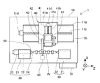
- the grinding machine 1 includes a bed 10, a headstock 20, a tailstock 30, a grindstone support device 40, a force sensor 50, a sizing device 60, and a control device 70. Is done.
- the coffin bed 10 has a substantially rectangular shape and is disposed on the floor.
- a pair of grinding wheel table guide rails 11 a and 11 b are formed in parallel to each other so as to extend in the left-right direction (Z-axis direction) in FIG. 1.
- the pair of grinding wheel table guide rails 11 a and 11 b are rails on which the grinding wheel table traverse base 41 constituting the grinding wheel support device 40 can slide.
- the bed 10 is provided with a grinding wheel base Z-axis ball screw 11c for driving the grinding wheel base traverse base 41 in the left-right direction in FIG. 1 between the pair of grinding wheel base guide rails 11a and 11b.
- a grinding wheel base Z-axis motor 11d for rotating the grinding wheel base Z-axis ball screw 11c is disposed.
- the spindle stock 20 (corresponding to the “supporting means” of the present invention) includes a spindle stock main body 21, a spindle 22, a spindle motor 23, and a spindle center 24.
- the headstock main body 21 is fixed to the lower left side of FIG. However, the headstock body 21 can slightly adjust the position in the Z-axis direction with respect to the bed 10.
- a main shaft 22 is inserted and supported so as to be rotatable about the axis (around the Z axis in FIG. 1).
- a spindle motor 23 is provided at the left end of the spindle 22 in FIG. 1, and the spindle 22 is rotationally driven by the spindle motor 23 with respect to the spindle head body 21.
- the main shaft motor 23 has an encoder, and the rotation angle of the main shaft motor 23 can be detected by the encoder.
- a spindle center 24 that supports one axial end of the shaft-like workpiece W is attached to the right end of the spindle 22.
- the tailstock 30 (corresponding to the “supporting means” of the present invention) includes a tailstock body 31 and a tailstock center 32.
- the tailstock body 31 is fixed to the lower right side of FIG. However, the tailstock body 31 can slightly adjust the position in the Z-axis direction with respect to the bed 10.
- the tailstock 31 is provided with a tailstock center 32 that cannot rotate with respect to the tailstock 31.
- the tailstock center 32 is located coaxially with the rotation axis of the main shaft 22.
- the tailstock center 32 supports the other end of the workpiece W in the axial direction. That is, the tailstock center 32 is disposed so as to face the spindle center 24. The both ends of the workpiece W are rotatably supported by the spindle center 24 and the tailstock center 32. Furthermore, the tailstock center 32 can change the amount of protrusion from the right end surface of the tailstock body 31. That is, the protrusion amount of the tailstock center 32 can be adjusted according to the position of the workpiece W. In this way, the workpiece W is held by the spindle center 24 and the tailstock center 32 so as to be rotatable around the spindle axis (around the Z axis).
- the whetstone support device 40 includes a whetstone traverse base 41, a whetstone base 42, a whetstone wheel 43 (corresponding to the “tool” of the present invention), and a whetstone rotation motor 44.
- the grinding wheel base traverse base 41 is formed in a rectangular flat plate shape, and is slidably disposed on the pair of grinding wheel base guide rails 11 a and 11 b in the upper surface of the bed 10.
- the wheel head traverse base 41 is connected to a nut member of the wheel head Z-axis ball screw 11c, and moves along the pair of wheel head guide rails 11a and 11b by driving the wheel head Z-axis motor 11d.
- This wheel head Z-axis motor 11d has an encoder, and the encoder can detect the rotation angle of the wheel head Z-axis motor 11d.
- a pair of X-axis guide rails 41a and 41b on which the grindstone table 42 can slide are extended on the upper surface of the grindstone table traverse base 41 so as to extend in the vertical direction (X-axis direction) in FIG. Is formed.
- the grinding wheel base traverse base 41 is provided with an X axis ball screw 41c for driving the grinding wheel base 42 in the vertical direction of FIG. 1 between the pair of X axis guide rails 41a and 41b.
- An X-axis motor 41d that rotationally drives the ball screw 41c is disposed.
- the X-axis motor 41d has an encoder, and the encoder can detect the rotation angle of the X-axis motor 41d.
- the whetstone head 42 is slidably disposed on the pair of X-axis guide rails 41 a and 41 b in the upper surface of the whetstone base traverse base 41.
- the grinding wheel base 42 is connected to a nut member of the X-axis ball screw 41c, and moves along the pair of X-axis guide rails 41a and 41b by driving the X-axis motor 41d. That is, the grindstone table 42 can move relative to the bed 10, the spindle stock 20 and the tailstock 30 in the X-axis direction (plunge feed direction) and the Z-axis direction (traverse feed direction).
- a grinding wheel rotating shaft member (not shown) is supported in the through hole of the grinding wheel base 42 so as to be rotatable around the central axis of the grinding wheel in parallel with the Z axis.
- a disc-shaped grinding wheel 43 (corresponding to the “tool” of the present invention) is coaxially attached to one end (the left end in FIG. 1) of the grinding wheel rotating shaft member. That is, the grinding wheel 43 is cantilevered with respect to the grinding wheel base 42. Specifically, the right end side of the grinding wheel 43 in FIG. 1 is supported by the grinding wheel base 42, and the left end side of the grinding wheel 43 in FIG. 1 is a free end.
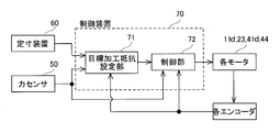
- the control device 70 (corresponding to “control means” and “target resistance setting means” of the present invention) controls each motor, rotates the workpiece W around the main axis, rotates the grinding wheel 43, and The outer peripheral surface of the workpiece W is ground by changing the relative positions of the grinding wheel 43 with respect to W in the Z-axis direction and the X-axis direction.
- the control device 70 may perform position control based on each position detected by each encoder, or may perform resistance control based on the machining resistance detected by the force sensor 50. Details will be described later.
- the control unit 72 processes the outer peripheral surface of the workpiece W by controlling the positions of the motors 11d and 41d based on information output from the encoders. Do. Further, the control unit 72 performs machining of the outer peripheral surface of the workpiece W by performing resistance control based on each target machining resistance set in the target machining resistance setting unit 71 and information output from the force sensor 50. Do.
- the processing of the control device 70 will be described in detail with reference to FIGS. 3, 4A, and 4B.
- a case where a plurality of workpieces W of the same type are continuously processed is targeted.
- the first workpiece W is referred to as an initial workpiece W1
- the second and subsequent workpieces Wn are referred to as continuous workpieces.
- the machining resistance is zero in the vacuum machining.
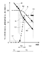
- the outer dimension of the workpiece at this time is D0 as shown by a in FIG. 4A.
- the behavior of the wheel head position at this time, that is, the feed speed of the grinding wheel 43 has an inclination as shown by b in FIG. 4A.
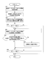
- next workpiece W it is determined whether or not the next workpiece W exists (S4). If there is no next workpiece W (S4: N), the process is terminated. On the other hand, when the next workpiece W, that is, the continuous workpiece Wn exists (S4: Y), machining is started for the continuous workpiece Wn (S5).
- the machining for the continuous workpiece Wn is controlled differently in the case of idle machining and in the case of machining (actual machining).
- the position control of the X-axis motor 41d is performed based on the position information detected by the encoder so as to coincide with the set feed speed of the grinding wheel 43 in the idle machining.
- the feed speed of the grinding wheel 43 at this time is the same as the feed speed of the grinding wheel 43 in the idle machining of the initial workpiece machining.
- the steady target machining resistance Rt stored in the target machining resistance setting unit 71 is reached based on the machining resistance detected by the force sensor 50.
- the X-axis motor 41d is controlled. That is, feedback control by machining resistance is performed on the continuous workpiece Wn.
- the feed speed of the grinding wheel 43 in the X-axis direction is controlled by resistance control.
- the machining resistance becomes constant as indicated by C3 in FIG. 4B.
- the workpiece outer dimension in the steady state decreases by a certain amount.
- the behavior of the wheel head position in the steady state that is, the feed speed of the grinding wheel 43 is constant as shown by B3 in FIG. 4B.
- resistance control is performed so that the feed speed of the grinding wheel 43 in the transient state is faster than the feed speed of the grinding wheel 43 in the steady state. Furthermore, in the transition from the transient state to the steady state, the resistance is controlled so that the feed speed of the grinding wheel 43 changes smoothly.
- the current outer diameter reduction amount Dn is measured.
- This outer diameter reduction amount Dn is measured by the sizing device 60. Specifically, the outer diameter reduction amount Dn per unit time in the steady state is measured. The difference ⁇ D between the outer diameter reduction amount Dn per unit time measured this time and the outer diameter reduction amount D1 per unit time in the steady state in the initial workpiece machining (corresponding to the “target reduction amount” of the present invention). Is calculated. Then, it is determined whether or not the difference ⁇ D in the outer diameter reduction amount is within a preset allowable value (S6).
- the steady target machining resistance Rt is corrected (S7).
- the steady target machining resistance Rt is corrected as follows. First, the steady target machining resistance Rt is multiplied by a value obtained by dividing the current outer diameter reduction amount Dn per unit time by the outer diameter reduction amount D1 per unit time in the initial workpiece machining. Then, the obtained value is set as a new steady target machining resistance Rt.
- the corrected steady target machining resistance Rt is set in the target machining resistance setting unit 71 as a new steady target machining resistance Rt.
- step S8 when the difference ⁇ D in the outer diameter reduction amount is within the allowable value (S6: Y) and after the steady target machining resistance is corrected in step S7, it is determined whether or not the next workpiece W exists. (S8). If the next workpiece W exists (S8: Y), the process returns to step S5 and is repeated. On the other hand, if there is no next workpiece W (S8: N), the process is terminated.
- FIG. 4B shows workpiece external dimensions, wheel head positions, and machining resistances in the idle state, the transient state of actual machining, and the steady state of actual machining.
- the radial feed speed of the grinding wheel 43 with respect to the workpiece W in the transient state of the continuous workpiece Wn is controlled to be faster than the feeding speed of the grinding wheel 43 in the steady state. That is, immediately after starting the machining of the continuous workpiece Wn (immediately after shifting from the blank machining to the actual machining), the feed speed of the grinding wheel 43 is controlled to be faster than the feed speed in the steady state, thereby machining the continuous workpiece Wn in the transient state. Time can be shortened.
- the control unit 72 performs resistance control on the continuous workpiece Wn at the time of machining.
- the control unit 72 can perform position control on the continuous workpiece Wn not only in the idle machining but also in the actual machining.
- the grindstone position (B1, B2, B3) that gives the behavior of the machining resistance (C1, C2, C3) of FIG. 4B is calculated. Keep it.
- This calculated wheel head position becomes a command value for position control.
- the control unit 72 controls the position of the X-axis motor 41d so as to be the position of the calculated grinding wheel head position (B1, B2, B3). That is, the feed speed of the grinding wheel 43 is directly controlled.
- control unit 72 controls the feed speed of the grinding wheel 43 in the transient state to be faster than the feed speed of the grinding wheel 43 in the steady state.
- processing time can be shortened as in the above-described embodiment.
Landscapes
- Engineering & Computer Science (AREA)
- Mechanical Engineering (AREA)
- Constituent Portions Of Griding Lathes, Driving, Sensing And Control (AREA)
- Grinding Of Cylindrical And Plane Surfaces (AREA)
Abstract
Description
軸状のワークを回転可能に支持する支持手段と、
前記支持手段に対して、前記ワークの径方向に相対移動可能な工具と、
前記支持手段と前記工具とを相対移動させて、前記ワークの周面を径方向に向かって加工する制御手段と、
を備え、
前記制御手段は、加工位置における前記ワークの径方向の撓み量が増加する過渡状態における前記工具の前記径方向の相対送り速度を、前記加工位置における前記ワークの径方向の撓み量が一定となる定常状態における前記工具の前記径方向の相対送り速度より早くするように制御することである。
前記工作機械は、
実加工において前記工具により前記ワークを加工する際に生じる加工抵抗を検出する加工抵抗検出手段と、
同種の前記ワークを以前に加工した際において、前記ワークの径方向の撓み量が一定となる定常状態における前記加工抵抗を定常目標加工抵抗として設定する目標加工抵抗設定手段と、
をさらに備え、
前記制御手段は、前記過渡状態において、現在の前記加工抵抗が前記目標加工抵抗に到達するように前記工具の前記径方向の送り速度を制御することである。
前記目標加工抵抗設定手段は、
前記定常目標加工抵抗を設定した際において、前記加工径計測手段により算出された前記定常状態における前記ワークの加工径の単位時間当たりの減少量を設定しておき、
今回の前記ワークを加工する際において、前記加工径計測手段により前記定常状態における前記ワークの今回の加工径の単位時間当たりの減少量を算出し、
前記今回の加工径の単位時間当たりの減少量を設定された前記加工径の単位時間当たりの減少量により除算した値を、前記定常目標加工抵抗に乗算し、
得られた値を新しい前記定常目標加工抵抗に設定することである。
なお、上述した請求項2~6に係る工作機械の発明は、請求項7に係る加工方法の発明に、実質的にそのまま適用可能である。
請求項6に係る発明によれば、定常目標加工抵抗の修正に関する具体的な処理方法を特定している。これらによれば、確実に、適切な定常目標加工抵抗を設定できる。
請求項7に係る発明によれば、請求項1に係る工作機械の発明における効果と実質的に同様の効果を奏することができる。また、他の工作機械に関する発明を、当該加工方法に適用した場合には、それぞれの効果と同一の効果を奏することができる。
本実施形態の工作機械の一例として、砥石台トラバース型円筒研削盤を例に挙げて説明する。そして、当該研削盤の加工対象ワークWは、カムシャフトやクランクシャフトなどの軸状のワークを例に挙げる。ただし、ワークWは、軸状であれば、カムシャフトやクランクシャフトの他にも適用可能である。
定寸装置60(本発明の「加工径計測手段」に相当する。)は、加工位置におけるワークWの外径を計測している。この定寸装置60により計測される信号は、制御装置70へ出力される。
一方、次のワークW、すなわち継続ワークWnが存在する場合には(S4:Y)、当該継続ワークWnに対して加工を開始する(S5)。継続ワークWnに対する加工は、空加工の場合と、加工(実加工)の場合とで異なる制御がされる。空加工における継続ワークWnに対する加工においては、エンコーダにより検出される位置情報に基づいて、設定された空加工における砥石車43の送り速度に一致するように、X軸モータ41dの位置制御を行う。このときの砥石車43の送り速度は、初期ワーク加工の空加工における砥石車43の送り速度と同一としている。
上記実施形態において、制御部72は、継続ワークWnに対して、加工の際には抵抗制御を行うこととした。この他に、制御部72は、継続ワークWnに対して、空加工のみならず、実加工においても、位置制御を行うようにすることもできる。この場合、まず、初期ワークW1の際に得られた情報に基づいて、図4Bの加工抵抗(C1,C2,C3)の挙動となるような砥石台位置(B1,B2,B3)を算出しておく。この算出された砥石台位置が、位置制御の指令値となる。そして、制御部72は、算出された砥石台位置(B1,B2,B3)の位置となるように、X軸モータ41dを位置制御する。つまり、砥石車43の送り速度を直接的に制御することとなる。
Claims (7)
- 軸状のワークを回転可能に支持する支持手段と、
前記支持手段に対して、前記ワークの径方向に相対移動可能な工具と、
前記支持手段と前記工具とを相対移動させて、前記ワークの周面を径方向に向かって加工する制御手段と、
を備え、
前記制御手段は、加工位置における前記ワークの径方向の撓み量が増加する過渡状態における前記工具の前記径方向の相対送り速度を、前記加工位置における前記ワークの径方向の撓み量が一定となる定常状態における前記工具の前記径方向の相対送り速度より早くするように制御することを特徴とする工作機械。 - 請求項1において、
前記過渡状態は、空加工から加工に移行した直後における状態であることを特徴とする工作機械。 - 請求項1または2において、
前記工作機械は、
実加工において前記工具により前記ワークを加工する際に生じる加工抵抗を検出する加工抵抗検出手段と、
同種の前記ワークを以前に加工した際において、前記ワークの径方向の撓み量が一定となる定常状態における前記加工抵抗を定常目標加工抵抗として設定する目標加工抵抗設定手段と、
をさらに備え、
前記制御手段は、前記過渡状態において、現在の前記加工抵抗が前記目標加工抵抗に到達するように前記工具の前記径方向の送り速度を制御することを特徴とする工作機械。 - 請求項3において、
前記制御手段は、前記過渡状態における現在の前記加工抵抗に応じて、前記工具の前記径方向の送り速度を変化させることを特徴とする工作機械。 - 請求項3または4において、
前記工作機械は、前記ワークの加工径を計測する加工径計測手段をさらに備え、
前記目標加工抵抗設定手段は、前記ワークを加工する際において、前記加工径計測手段により計測した前記ワークの加工径に基づいて、前記定常目標加工抵抗を修正することを特徴とする工作機械。 - 請求項5において、
前記目標加工抵抗設定手段は、
前記定常目標加工抵抗を設定した際において、前記加工径計測手段により算出された前記定常状態における前記ワークの加工径の単位時間当たりの減少量を設定しておき、
今回の前記ワークを加工する際において、前記加工径計測手段により前記定常状態における前記ワークの今回の加工径の単位時間当たりの減少量を算出し、
前記今回の加工径の単位時間当たりの減少量を設定された前記加工径の単位時間当たりの減少量により除算した値を、前記定常目標加工抵抗に乗算し、
得られた値を新しい前記定常目標加工抵抗に設定することを特徴とする工作機械。 - 軸状のワークを回転させながら、前記ワークの径方向に前記ワークと工具とを相対移動させることにより、前記ワークの周面を径方向に向かって加工する加工方法において、
加工位置における前記ワークの径方向の撓み量が増加する過渡状態における前記工具の前記径方向の相対送り速度を、前記加工位置における前記ワークの径方向の撓み量が一定となる定常状態における前記工具の前記径方向の相対送り速度より早くするように制御することを特徴とする加工方法。
Priority Applications (3)
| Application Number | Priority Date | Filing Date | Title |
|---|---|---|---|
| US13/394,352 US8900034B2 (en) | 2009-09-11 | 2010-09-10 | Machine tool and machining method |
| CN201080040217.5A CN102481680B (zh) | 2009-09-11 | 2010-09-10 | 机床以及加工方法 |
| EP10815460.0A EP2476513B1 (en) | 2009-09-11 | 2010-09-10 | Machine tool and machining method |
Applications Claiming Priority (2)
| Application Number | Priority Date | Filing Date | Title |
|---|---|---|---|
| JP2009210113A JP5353586B2 (ja) | 2009-09-11 | 2009-09-11 | 工作機械および加工方法 |
| JP2009-210113 | 2009-09-11 |
Publications (1)
| Publication Number | Publication Date |
|---|---|
| WO2011030866A1 true WO2011030866A1 (ja) | 2011-03-17 |
Family
ID=43732534
Family Applications (1)
| Application Number | Title | Priority Date | Filing Date |
|---|---|---|---|
| PCT/JP2010/065651 Ceased WO2011030866A1 (ja) | 2009-09-11 | 2010-09-10 | 工作機械および加工方法 |
Country Status (5)
| Country | Link |
|---|---|
| US (1) | US8900034B2 (ja) |
| EP (1) | EP2476513B1 (ja) |
| JP (1) | JP5353586B2 (ja) |
| CN (1) | CN102481680B (ja) |
| WO (1) | WO2011030866A1 (ja) |
Cited By (1)
| Publication number | Priority date | Publication date | Assignee | Title |
|---|---|---|---|---|
| JP2018525235A (ja) * | 2015-07-08 | 2018-09-06 | スカニア シーブイ アクチボラグ | 円筒形状の軸受表面を有するワークピースを研削する方法および処理パラメーターを決定するための方法 |
Families Citing this family (11)
| Publication number | Priority date | Publication date | Assignee | Title |
|---|---|---|---|---|
| JP5423313B2 (ja) * | 2009-10-26 | 2014-02-19 | 株式会社ジェイテクト | 研削盤および研削方法 |
| JP5418148B2 (ja) * | 2009-10-28 | 2014-02-19 | 株式会社ジェイテクト | 研削盤および研削方法 |
| JP5708324B2 (ja) * | 2011-07-11 | 2015-04-30 | 日本精工株式会社 | 研削加工盤及び研削加工方法 |
| JP6102480B2 (ja) * | 2013-05-08 | 2017-03-29 | 株式会社ジェイテクト | 研削盤および研削方法 |
| CN106514441A (zh) * | 2015-12-04 | 2017-03-22 | 重庆江陆激光科技有限公司 | 拉丝抛光工装 |
| JP6972555B2 (ja) * | 2017-01-06 | 2021-11-24 | 株式会社ジェイテクト | 研削加工装置及び研削加工方法 |
| JP6537537B2 (ja) * | 2017-01-10 | 2019-07-03 | ミクロン精密株式会社 | センタレス研削装置および荷重測定方法 |
| WO2018131399A1 (ja) * | 2017-01-10 | 2018-07-19 | ミクロン精密株式会社 | 研削装置および研削方法 |
| JP6576370B2 (ja) * | 2017-01-10 | 2019-09-18 | ミクロン精密株式会社 | 研削装置および研削方法 |
| CN114888648A (zh) * | 2022-07-08 | 2022-08-12 | 游隼信息技术科技(苏州)有限公司 | 一种轴类磨削加工设备 |
| CN115805506A (zh) * | 2023-02-09 | 2023-03-17 | 太原市三高能源发展有限公司 | 一种机械配件铸造用打磨装置及使用方法 |
Citations (4)
| Publication number | Priority date | Publication date | Assignee | Title |
|---|---|---|---|---|
| JPH07214466A (ja) | 1994-01-31 | 1995-08-15 | Toyoda Mach Works Ltd | 研削装置 |
| JPH08168957A (ja) * | 1994-09-30 | 1996-07-02 | Toyoda Mach Works Ltd | 研削装置 |
| JP2000263437A (ja) * | 1999-03-16 | 2000-09-26 | Mitsubishi Heavy Ind Ltd | 円筒研削盤 |
| JP2003275957A (ja) * | 2002-03-25 | 2003-09-30 | Toyo Advanced Technologies Co Ltd | 研削加工方法及び装置 |
Family Cites Families (17)
| Publication number | Priority date | Publication date | Assignee | Title |
|---|---|---|---|---|
| US2802312A (en) * | 1953-11-13 | 1957-08-13 | Cincinnati Milling Machine Co | Grinding machine |
| US2984952A (en) * | 1958-04-29 | 1961-05-23 | Landis Tool Co | Pressure operated feed control for grinding machines |
| US3247620A (en) * | 1963-11-15 | 1966-04-26 | Landis Tool Co | Multiple position feed mechanism |
| JPS4840860B1 (ja) * | 1970-08-28 | 1973-12-03 | ||
| IT959396B (it) * | 1972-06-06 | 1973-11-10 | Finike Italiana Marposs | Dispositivo di controllo della velocita di accostamento in mac chine utensili in particolare rettificatrici |
| JPS5712663B2 (ja) * | 1973-10-29 | 1982-03-12 | ||
| US4118900A (en) | 1976-03-29 | 1978-10-10 | Seiko Seiki Kabushiki Kaisha | Method for controlling grinding process |
| US4187646A (en) * | 1976-08-16 | 1980-02-12 | The Valeron Corporation | Apparatus for grinding |
| JP3490534B2 (ja) * | 1995-03-23 | 2004-01-26 | オークマ株式会社 | 非円形工作物の研削加工方法及び装置 |
| JP3589546B2 (ja) * | 1997-04-08 | 2004-11-17 | 富士通株式会社 | 自動ラッピング方法及びその装置 |
| JP2002292560A (ja) * | 2001-03-29 | 2002-10-08 | Toyo Advanced Technologies Co Ltd | 研削加工方法及び装置 |
| DE10149175A1 (de) * | 2001-10-04 | 2003-04-17 | Heidenhain Gmbh Dr Johannes | Verfahren zur Bahnsteuerung |
| JP2004114195A (ja) * | 2002-09-25 | 2004-04-15 | Toyoda Mach Works Ltd | 研削方法及び円筒研削盤 |
| DE602004006654T2 (de) * | 2003-02-12 | 2008-02-07 | Nissan Motor Co., Ltd., Yokohama | Vorrichtung und Verfahren zur Oberflächen-Endbearbeitung |
| JP4858456B2 (ja) * | 2008-01-29 | 2012-01-18 | トヨタ自動車株式会社 | カムシャフトの製造方法 |
| CN101259554A (zh) * | 2008-04-24 | 2008-09-10 | 上海交通大学 | 微细电火花电极损耗定长补偿方法 |
| US8517797B2 (en) * | 2009-10-28 | 2013-08-27 | Jtekt Corporation | Grinding machine and grinding method |
-
2009
- 2009-09-11 JP JP2009210113A patent/JP5353586B2/ja not_active Expired - Fee Related
-
2010
- 2010-09-10 CN CN201080040217.5A patent/CN102481680B/zh not_active Expired - Fee Related
- 2010-09-10 US US13/394,352 patent/US8900034B2/en not_active Expired - Fee Related
- 2010-09-10 WO PCT/JP2010/065651 patent/WO2011030866A1/ja not_active Ceased
- 2010-09-10 EP EP10815460.0A patent/EP2476513B1/en not_active Not-in-force
Patent Citations (4)
| Publication number | Priority date | Publication date | Assignee | Title |
|---|---|---|---|---|
| JPH07214466A (ja) | 1994-01-31 | 1995-08-15 | Toyoda Mach Works Ltd | 研削装置 |
| JPH08168957A (ja) * | 1994-09-30 | 1996-07-02 | Toyoda Mach Works Ltd | 研削装置 |
| JP2000263437A (ja) * | 1999-03-16 | 2000-09-26 | Mitsubishi Heavy Ind Ltd | 円筒研削盤 |
| JP2003275957A (ja) * | 2002-03-25 | 2003-09-30 | Toyo Advanced Technologies Co Ltd | 研削加工方法及び装置 |
Non-Patent Citations (1)
| Title |
|---|
| See also references of EP2476513A4 * |
Cited By (1)
| Publication number | Priority date | Publication date | Assignee | Title |
|---|---|---|---|---|
| JP2018525235A (ja) * | 2015-07-08 | 2018-09-06 | スカニア シーブイ アクチボラグ | 円筒形状の軸受表面を有するワークピースを研削する方法および処理パラメーターを決定するための方法 |
Also Published As
| Publication number | Publication date |
|---|---|
| EP2476513A1 (en) | 2012-07-18 |
| JP2011056629A (ja) | 2011-03-24 |
| EP2476513A4 (en) | 2014-09-03 |
| EP2476513B1 (en) | 2016-08-17 |
| US8900034B2 (en) | 2014-12-02 |
| CN102481680B (zh) | 2014-08-20 |
| CN102481680A (zh) | 2012-05-30 |
| US20120164920A1 (en) | 2012-06-28 |
| JP5353586B2 (ja) | 2013-11-27 |
Similar Documents
| Publication | Publication Date | Title |
|---|---|---|
| JP5353586B2 (ja) | 工作機械および加工方法 | |
| JP5359320B2 (ja) | 工作機械 | |
| WO2011010528A1 (ja) | 工作物のスリップ防止方法および装置 | |
| JP2020044618A (ja) | 研削盤及び研削方法 | |
| JP2011093017A (ja) | 研削盤および研削方法 | |
| JP5218103B2 (ja) | 工作機械 | |
| JP5125391B2 (ja) | 旋回装置およびそれを備えた円筒研削盤 | |
| JP6102502B2 (ja) | 研削盤および研削方法 | |
| JP6102480B2 (ja) | 研削盤および研削方法 | |
| JP4730944B2 (ja) | 多頭研削盤及び多頭研削盤を用いた研削方法 | |
| JP7326843B2 (ja) | 研削方法及び研削盤 | |
| JP2011104675A (ja) | 研削盤および研削方法 | |
| JP5423313B2 (ja) | 研削盤および研削方法 | |
| JP3148034B2 (ja) | ギアホーニング加工方法及び装置 | |
| JP5262577B2 (ja) | 研削加工方法および研削盤 | |
| JP3344064B2 (ja) | 研削装置 | |
| JP5515480B2 (ja) | センタ加圧力自動制御装置 | |
| JP6903876B2 (ja) | 研削装置及び研削方法 | |
| JP2009220191A (ja) | 加工方法及び加工機 | |
| JP3836098B2 (ja) | クランクピンの研削方法及び研削装置 | |
| JP5332658B2 (ja) | 工作機械 | |
| JP2973197B1 (ja) | Cnc研削盤による研削方法 | |
| JP2003117813A (ja) | ワークレスト装置及びその制御方法 | |
| JPH06278021A (ja) | 研削装置 | |
| JPH0360971A (ja) | 研削砥石の研削面修正方法 |
Legal Events
| Date | Code | Title | Description |
|---|---|---|---|
| WWE | Wipo information: entry into national phase |
Ref document number: 201080040217.5 Country of ref document: CN |
|
| 121 | Ep: the epo has been informed by wipo that ep was designated in this application |
Ref document number: 10815460 Country of ref document: EP Kind code of ref document: A1 |
|
| REEP | Request for entry into the european phase |
Ref document number: 2010815460 Country of ref document: EP |
|
| WWE | Wipo information: entry into national phase |
Ref document number: 2010815460 Country of ref document: EP |
|
| WWE | Wipo information: entry into national phase |
Ref document number: 13394352 Country of ref document: US |
|
| NENP | Non-entry into the national phase |
Ref country code: DE |