WO2011030901A1 - 航空機の操縦システム - Google Patents
航空機の操縦システム Download PDFInfo
- Publication number
- WO2011030901A1 WO2011030901A1 PCT/JP2010/065780 JP2010065780W WO2011030901A1 WO 2011030901 A1 WO2011030901 A1 WO 2011030901A1 JP 2010065780 W JP2010065780 W JP 2010065780W WO 2011030901 A1 WO2011030901 A1 WO 2011030901A1
- Authority
- WO
- WIPO (PCT)
- Prior art keywords
- steering position
- aircraft
- command
- steering
- change amount
- Prior art date
- Legal status (The legal status is an assumption and is not a legal conclusion. Google has not performed a legal analysis and makes no representation as to the accuracy of the status listed.)
- Ceased
Links
Images








Classifications
-
- B—PERFORMING OPERATIONS; TRANSPORTING
- B64—AIRCRAFT; AVIATION; COSMONAUTICS
- B64C—AEROPLANES; HELICOPTERS
- B64C13/00—Control systems or transmitting systems for actuating flying-control surfaces, lift-increasing flaps, air brakes, or spoilers
- B64C13/24—Transmitting means
- B64C13/26—Transmitting means without power amplification or where power amplification is irrelevant
- B64C13/28—Transmitting means without power amplification or where power amplification is irrelevant mechanical
- B64C13/345—Transmitting means without power amplification or where power amplification is irrelevant mechanical with artificial feel
Definitions
- the present invention relates to an aircraft control system and an aircraft control method.
- Pilots must be aware of the constantly changing status of aircraft output systems and flight control systems when maneuvering aircraft. The pilot needs to know not only the current state of these systems, but also their operational limits.
- Some aircraft use mechanical springs, and a tactile cue is provided to the pilot via the control lever to point out that the aircraft's operational limits are approaching.
- a mechanical spring interlocks at a set predetermined level and supplies a predetermined resistance to the control. The preset level cannot be changed once the spring is installed.
- Patent Document 1 Japanese Patent Publication No. 2004-516970 discloses an aircraft output that can change the magnitude of contact force according to predetermined dynamic conditions of an aircraft and does not require a mechanical spring.
- a lever tactile cueing system is disclosed.
- the mechanical spring is replaced by computer controlled software, a variable magnetic particle friction clutch, and an electronic trim motor.
- Output lever soft stop and output lever back drive are used as tactile alarms.
- These haptic alarms provide a spring-like haptic cue when the output command reaches a predetermined operating limit.
- the backdrive command causes the output lever to trim down at a variable speed based on aircraft and engine operating conditions.
- the haptic cue remains activated until the aircraft and engine are not in excess of operational limits.
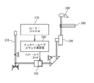
- FIG. 1 discloses a conventional steering system using an inner loop command.
- the control system includes a control device 210, a control surface actuator 230, a swash plate 240, a control surface 250, an inner loop actuator 260, a rate gyro 270, and an inner loop command calculation unit 280.
- the control surface actuator 230 is connected to the control device 210 via the inner loop actuator 260 and is connected to the control surface 250 via the swash plate 240.
- the control surface actuator 230 drives the control surface based on the steering position of the control device 210.
- the rate gyro 270 detects a change in posture due to disturbance of the airframe and outputs it to the inner loop command calculation unit 280.
- the inner loop command calculation unit 280 outputs an inner loop command based on the posture change.
- the inner loop command is a command for increasing or decreasing the command amount given to the control surface actuator 230 without changing the steering position of the pilot device 210 by the pilot.
- the inner loop actuator 260 drives the control surface 250 via the control surface actuator 230 based on the inner loop command. Therefore, even if the pilot keeps the steering position of the control device 210 constant without performing fine correction steering, it is possible to prevent the airframe from becoming unstable due to disturbance.
- An object of the present invention is to provide an aircraft maneuvering system and an aircraft maneuvering method in which an excess of operational restrictions relating to flight conditions is prevented even when a pilot operates a maneuver device quickly.
- An aircraft control system includes a control device, a sensor that detects a first specification that varies depending on a flight state of the aircraft, and the first specification that reaches a limit value based on the first specification.
- a limit steering position calculation unit that calculates a limit steering position of the control device, a reaction force generation command calculation unit that generates a reaction force generation command based on the steering position of the control device and the limit steering position, and the reaction force
- a reaction force generating actuator that changes a reaction force received when a pilot performs a steering input to the control device based on a generation command, and an inner loop that generates an inner loop command based on the steering position
- a command calculation unit and a control surface actuator that drives the control surface of the aircraft based on the steering position and the inner loop command; That.
- the inner loop command calculation unit generates the inner loop command so that the inner loop command depends on a time change rate of the steering position.
- the control surface actuator drives the control surface so that the drive amount of the control surface decreases when the steering position changes rapidly.
- the aircraft control system further includes an inner loop actuator that operates based on the inner loop command.
- the control surface actuator drives the control surface based on the steering position and the output displacement of the inner loop actuator.
- the aircraft control system further includes a flight control calculation unit and a control surface command calculation unit.
- the flight control calculation unit generates a steering command based on the steering position.
- the control surface command calculation unit generates a control surface command by subtracting the inner loop command from the steering command.
- the control surface actuator drives the control surface based on the control surface command.
- the sensor detects a plurality of specifications including the first specification.
- the plurality of specifications vary depending on the flight state.
- the limited steering position calculation unit calculates the limited steering position based on a table in which combinations of the values of the plurality of specifications are associated with the limited steering position.
- the limited steering position calculation unit calculates a steering position change amount based on a difference between the limit value and the first specification and a ratio of the change amount of the first specification to the change amount of the steering position.
- the limited steering position is calculated based on the steering position change amount and the steering position.
- the sensor further detects a plurality of specifications different from the first specification.
- the plurality of specifications vary depending on the flight state.
- the limited steering position calculation unit calculates the steering position change amount based on the difference, the plurality of specifications, a table in which the combination of the values of the plurality of specifications and the ratio are associated with each other.
- the sensor further detects a plurality of specifications different from the first specification.
- the plurality of specifications vary depending on the flight state.
- the limited steering position calculation unit calculates a first specification predicted value as a predicted value after a predetermined prediction time of the first specification, the difference between the limited value and the first specification predicted value, A steering position change amount is calculated based on a table in which a plurality of specifications, a combination of values of the plurality of specifications, and a ratio of the change amount of the first specification to the change amount of the steering position are associated with each other, The limited steering position is calculated based on the steering position change amount and the steering position.
- the sensor further detects a plurality of specifications different from the first specification.
- the plurality of specifications vary depending on the flight state.
- the limited steering position calculation unit calculates a first specification prediction value as a prediction value after a predetermined prediction time of the first specification, the first specification prediction value, the first specification, A first specification correction value as a correction value of the first specification prediction value is calculated based on a buffer in which the prediction time is set as a holding time and a filter, and the limit value and the first specification are calculated. Steering based on a correction value difference, the plurality of specifications, a combination of values of the plurality of specifications, and a table in which the ratio of the change amount of the first specification to the change amount of the steering position is associated. A position change amount is calculated, and the limited steering position is calculated based on the steering position change amount and the steering position.
- An aircraft maneuvering method includes a step of detecting a first specification that varies depending on a flight state of an aircraft, and a limited steering of a control device that reaches the limit value based on the first specification.
- a step of calculating a position; a step of generating a reaction force generation command based on the steering position of the control device and the limited steering position; and a pilot steering input to the control device based on the reaction force generation command A control surface of the aircraft based on the steering position and the inner loop command based on the steering position and the inner loop command.
- the inner loop command is generated so that the inner loop command depends on a time change rate of the steering position.
- the control surface is driven so that the driving amount of the control surface decreases when the steering position changes rapidly.
- the control device is connected to the control surface via an inner loop actuator and a control surface actuator.
- the step of driving the control surface includes the step of operating the inner loop actuator based on the inner loop command, the control surface actuator including the steering position and the output displacement of the inner loop actuator. And driving the control surface based on
- the aircraft maneuvering method further includes a step of generating a steering command based on the steering position and a step of generating a control surface command by subtracting the inner loop command from the steering command.
- the control surface is driven based on the control surface command.
- a plurality of items including the first item are detected.
- the plurality of specifications vary depending on the flight state.
- the limit steering position is calculated based on a table in which the combination of the values of the plurality of specifications is associated with the limit steering position.
- the step of calculating the limit steering position is based on the difference between the limit value and the first specification, and the ratio of the change amount of the first specification to the change amount of the steering position. And calculating the limit steering position based on the steering position change amount and the steering position.
- the aircraft control method further includes a step of detecting a plurality of specifications different from the first specification.
- the plurality of specifications vary depending on the flight state.
- the steering position change amount is calculated on the basis of the difference, the plurality of specifications, a combination of the values of the plurality of specifications and the ratio. To do.
- the aircraft control method further includes a step of detecting a plurality of specifications different from the first specification.
- the plurality of specifications vary depending on the flight state.
- the step of calculating the limit steering position includes a step of calculating a first specification prediction value as a prediction value after a predetermined prediction time of the first specification, and the limit value and the first specification prediction value. Steering position change based on a table in which the difference between the plurality of specifications, the combination of the values of the plurality of specifications, and the ratio of the change amount of the first specification to the change amount of the steering position are associated with each other Calculating the amount, and calculating the limit steering position based on the steering position change amount and the steering position.
- the aircraft control method further includes a step of detecting a plurality of specifications different from the first specification.
- the plurality of specifications vary depending on the flight state.
- the step of calculating the limit steering position includes a step of calculating a first specification prediction value as a prediction value after a predetermined prediction time of the first specification, the first specification prediction value, Calculating a first specification correction value as a correction value of the first specification prediction value based on one specification, a buffer in which the prediction time is set as a holding time, and a filter;
- the difference between the value and the first specification correction value, the plurality of specifications, the combination of the values of the plurality of specifications, and the ratio of the change amount of the first specification to the change amount of the steering position are associated with each other. Calculating a steering position change amount based on the table, and calculating the limit steering position based on the steering position change amount and the steering position.
- FIG. 1 is a schematic diagram of a conventional maneuvering system using an inner loop command.
- FIG. 2 is a schematic diagram of the steering system according to the first embodiment of the present invention.
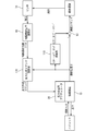
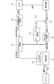
- FIG. 3 is a block diagram of the steering system according to the first embodiment.
- FIG. 4 is a block diagram of the inner loop command calculation unit.
- FIG. 5 is a block diagram of the limited steering position calculation unit.
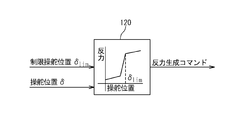
- FIG. 6 is a block diagram of the reaction force generation command calculation unit.
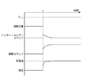
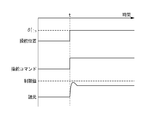
- FIG. 7 is a timing chart for explaining the operation of the steering system according to the first embodiment.
- FIG. 8 is a timing chart for explaining the operation of the steering system according to the first comparative example.
- FIG. 9 is a timing chart for explaining the operation of the steering system according to the second comparative example.
- FIG. 1 is a schematic diagram of a conventional maneuvering system using an inner loop command.
- FIG. 2 is a schematic diagram of the steering system according to the first embodiment of the present invention.
- FIG. 3 is a block diagram of
- FIG. 10 is a schematic view of a steering system according to the second embodiment of the present invention.
- FIG. 11 is a block diagram of a steering system according to the second embodiment.
- FIG. 12 is a block diagram of a limited steering position calculation unit according to the third embodiment of the present invention.
- FIG. 13 is a block diagram of a limited steering position calculation unit according to the fourth embodiment of the present invention.
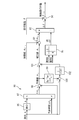
- FIG. 14 is a block diagram of a limited steering position calculation unit according to the fifth embodiment of the present invention.
- FIG. 15 is a block diagram of a limited steering position calculation unit according to the sixth embodiment of the present invention.
- FIG. 16 is a timing chart for explaining the operation of the steering system according to the second embodiment.
- the control system which concerns on the 1st Embodiment of this invention is demonstrated.
- the control system according to the present embodiment is a powered flight-control system and is applied to an aircraft such as a helicopter.
- the mobility control system is, for example, a hydromechanical control system.
- the steering system according to the present embodiment includes a steering device 10, a reaction force generating actuator 20, a control surface actuator 30, a swash plate 40, a control surface 50, an inner loop actuator 60, a sensor 70, A control device 80 is provided.
- the control device 80 includes a limited steering position calculation unit 90, an inner loop command calculation unit 110, and a reaction force generation command calculation unit 120.
- the control device 10 is connected to the control surface 50 via an inner loop actuator 60, a control surface actuator 30, and a swashplate 40.
- the inner loop actuator 60 includes a first portion 61 and a second portion 62.
- the control surface actuator 30 includes an input unit 31 and an output unit 32.
- the first portion 61 is connected to the control device 10.
- the second part 62 is connected to the input unit 31.
- the output unit 32 is connected to the control surface 50 via the swash plate 40.
- the sensor 70 detects at least the specifications of the airframe motion that change depending on the flight state of the aircraft, and outputs a specification signal indicating the detected specifications to the control device 80.
- the reaction force generation actuator 20 detects the steering position of the steering device 10 and outputs a steering position signal indicating the detected steering position to the control device 80.
- the control device 80 outputs an inner loop command to the inner loop actuator 60 and outputs a reaction force generation command to the reaction force generation actuator 20.
- the inner loop actuator 60 operates based on the inner loop command. More specifically, the relative position of the second portion 62 with respect to the first portion 61 changes based on the inner loop command. The relative position of the second portion 62 with respect to the first portion 61 may be referred to as the output displacement of the inner loop actuator 60.
- the reaction force generation actuator 20 changes the reaction force received when the pilot makes a steering input to the control device 10 based on the reaction force generation command.
- FIG. 3 shows a block diagram of the steering system according to the present embodiment.
- the steering position ⁇ of the control device 10 changes depending on pilot steering input.
- the inner loop command calculation unit 110 generates an inner loop command based on the steering position signal indicating the steering position ⁇ .
- inner loop command calculation unit 110 includes a high-pass filter 111.
- the inner loop command corresponds to the output of the high-pass filter 111 that receives a steering position signal indicating the steering position ⁇ . More specifically, the inner loop command is obtained by multiplying the output of the transfer function G 111 (s) that receives the steering position signal by the gain K.
- the transfer function G 111 (s) is expressed by the following equation (1), where ⁇ is a time constant. In this way, an inner loop command that depends on the time change rate of the steering position ⁇ is generated. (Equation 1)
- the inner loop actuator 60 operates based on the inner loop command, whereby the output displacement of the inner loop actuator 60 changes.
- the position of the second portion 62 is determined by subtracting the output displacement of the inner loop actuator 60 based on the inner loop command into the position of the first portion 61.
- the control surface actuator 30 drives the control surface 50 based on the position of the second portion 62 as a steering command. Since the first portion 61 is interlocked with the steering position ⁇ , the control surface actuator 30 drives the control surface 50 based on the steering position ⁇ and the output displacement of the inner loop actuator 60. That is, the control surface actuator 30 drives the control surface 50 based on the steering position ⁇ and the inner loop command.
- the sensor 70 detects specifications of the airframe motion that changes depending on the flight state of the aircraft, and outputs a specification signal indicating the detected specifications.
- the specifications are engine torque, bank angle, forward speed, lateral speed, main rotor speed, and the like.
- the sensor 70 detects a plurality of specifications A to C.
- the specification A is affected by the control surface 50.
- the limited steering position calculation unit 90 calculates the limited steering position ⁇ lim of the control device 10 at which the specification A reaches the limit value based on the specification signal indicating the specifications A to C.
- restricted steering position calculation unit 90 includes a table 91 in which combinations of values of specifications A to C are associated with restricted steering position ⁇ lim .
- the limited steering position calculation unit 90 calculates the limited steering position ⁇ lim based on the table 91.
- the method of calculating such a limit steering position [delta] lim is specifications B limit steering position [delta] lim not only specifications A, is effective when also on C.
- reaction force generation command calculation unit 120 generates a reaction force indicating a reaction force that the pilot should receive from control device 10 based on a steering position signal indicating steering position ⁇ and a limited steering position ⁇ lim. Generate a command. The reaction force generation command is generated so that the reaction force suddenly increases when the steering position ⁇ is close to the limit steering position ⁇ lim .
- the reaction force generation actuator 20 changes the reaction force received when the pilot performs a steering input to the control device 10 based on the reaction force generation command.
- FIG. 7 shows a case where the pilot keeps the steering position ⁇ constant before time t by the steering input, rapidly changes (increases) the steering position ⁇ to the limit steering position ⁇ lim at time t, and then keeps it constant thereafter.
- 4 shows changes in the specification A affected by the steering position ⁇ , the inner loop command, the steering command, and the control surface 50.
- the steering command is the position of the second portion 62.
- the pilot recognizes the restriction steering position [delta] lim based on the change in the reaction force received from the control apparatus 10, after the steering position [delta] has reached the limit steering position [delta] lim is holding the steering position [delta] restriction steering position [delta] lim To do.
- the inner loop command is held at a constant value (for example, zero) before time t, changes (increases) quickly at time t, and then gradually approaches a value before time t.
- the steering command as the position of the second portion 62 is determined from time t.
- the previous position is held constant, and after changing to a position corresponding to the limited steering position ⁇ lim after time t, the position is held at a position corresponding to the limited steering position ⁇ lim .
- the change of the position of the second portion 62 after time t is more gradual than the change of the steering position ⁇ at time t.
- the specification A is held at a constant value before the time t, changes to the limit value after the time t, and then held constant at the limit value.
- the control surface actuator 30 drives the control surface 50 based on an inner loop command based on the steering position ⁇ .
- the control surface actuator 30 controls the control surface 50 so that the driving amount of the control surface 50 decreases when the steering position ⁇ changes rapidly based on an inner loop command that depends on the time change rate of the steering position ⁇ . Drive. Therefore, the specification A is prevented from exceeding the limit value in the transient response.
- the specification A since the pilot holds the steering position ⁇ of the control device 10 at the limited steering position ⁇ lim based on the reaction force change, the specification A is held constant at the limit value in the steady response. Since the specification A is prevented from exceeding the limit value in the transient response, the aircraft is prevented from becoming unstable. Furthermore, since the specification A is kept constant at the limit value in the steady response, the maneuvering that makes the best use of the performance of the aircraft becomes possible.
- the inner loop command may be generated by an algorithm different from the algorithm shown in FIG. 4 as long as the same effect as described above can be obtained.
- the steering position ⁇ in the first comparative example, the steering command as the position of the second portion 62, and the specification A affected by the control surface 50 explain the change.
- the inner loop command is invalidated and the relative position of the second portion 62 with respect to the first portion 61 is fixed.
- the steering position ⁇ changes as in the case of FIG. Since the relative position of the second part 62 with respect to the first part 61 is fixed, the position of the second part 62 is linked to the steering position ⁇ . Therefore, the steering command as the position of the second portion 62 is held constant before the time t, quickly changes to a certain position at the time t, and thereafter held constant at that position.
- the specification A is held at a constant value before the time t, suddenly changes at the time t, temporarily exceeds the limit value, takes the maximum value, decreases to the limit value, and remains constant at the limit value Retained.
- the specification A exceeds the limit value in the transient response, the aircraft becomes unstable.
- the steering position ⁇ in the second comparative example the steering command as the position of the second portion 62, and the specification A affected by the control surface 50 I will explain the change.
- the inner loop command is disabled, the relative position of the second portion 62 with respect to the first portion 61 is fixed, and the limited steering position calculation unit 90 is replaced with the limited steering position ⁇ lim .
- the limited steering position ⁇ lim ′ is calculated.
- the limit steering position ⁇ lim ′ is set so that the specification A does not exceed the limit value at the maximum value of the transient response.
- the steering position ⁇ is held constant before the time t by the pilot input by the pilot, and the steering position ⁇ is rapidly changed to the limit steering position ⁇ lim ′ at the time t and then held constant thereafter. Since the relative position of the second part 62 with respect to the first part 61 is fixed, the position of the second part 62 is linked to the steering position ⁇ . Therefore, the steering command as the position of the second portion 62 is held constant before the time t, quickly changes to a certain position at the time t, and thereafter held constant at that position.
- the change amount at the time t of the steering command shown in FIG. 9 is smaller than the change amount at the time t of the steering command shown in FIG.
- the specification A is held at a constant value before the time t, changes suddenly at the time t to reach the vicinity of the limit value, and then becomes constant at a value slightly returned toward the constant value before the time t. Retained.
- the specification A is kept constant at a value that deviates from the limit value in the steady response, so that the maneuvering that makes the best use of the performance of the aircraft is not realized.
- overshoot exceeding the limit value of the specification occurs.
- the overshoot shape does not change and asymptotically approaches the limit value.
- the control system according to the present embodiment is a fly-by-wire control system, and is applied to an aircraft such as a helicopter.
- the steering system according to the present embodiment includes a steering device 10, a reaction force generating actuator 20, a control surface actuator 35, a swash plate 40, a control surface 50, a sensor 70, and a control device 85.
- the control device 85 includes a limited steering position calculation unit 90, an inner loop command calculation unit 110, a reaction force generation command calculation unit 120, a flight control calculation unit 140, and a control surface command calculation unit 150.
- the control surface actuator 35 is connected to the control surface 50 via the swash plate 40.
- the sensor 70 detects the specifications of the airframe motion that changes depending on the flight state of the aircraft, and outputs a specification signal indicating the detected specifications to the control device 85.
- the reaction force generation actuator 20 detects the steering position of the steering device 10 and outputs a steering position signal indicating the detected steering position to the control device 85.
- the control device 85 outputs a reaction force generation command to the reaction force generation actuator 20 and outputs a control surface command as an electric signal or an optical signal to the control surface actuator 35.
- the reaction force generation actuator 20 changes the reaction force received when the pilot makes a steering input to the control device 10 based on the reaction force generation command.
- the control surface actuator 35 drives the control surface 50 via the swash plate 40 based on the control surface command.
- FIG. 11 shows a block diagram of the steering system according to the present embodiment.
- the steering position ⁇ of the control device 10 changes depending on pilot steering input.
- the inner loop command calculation unit 110 is configured in the same manner as in the first embodiment. Similar to the first embodiment, the inner loop command calculation unit 110 generates an inner loop command based on a steering position signal indicating the steering position ⁇ .
- the flight control calculation unit 140 generates a steering command based on the steering position ⁇ .
- the control surface command calculation unit 150 is, for example, a subtracter.
- the control surface command calculation unit 150 generates a control surface command by subtracting the inner loop command from the steering command.
- the control surface actuator 35 drives the control surface 50 based on the control surface command. That is, the control surface actuator 35 drives the control surface 50 based on the steering command and the inner loop command.
- the sensor 70 is configured similarly to the first embodiment. As in the first embodiment, the sensor 70 detects a plurality of specifications A to C, and outputs a specification signal indicating the detected specifications.
- the limited steering position calculation unit 90 is configured in the same manner as in the first embodiment. As in the first embodiment, the limited steering position calculation unit 90 calculates the limited steering position ⁇ lim of the control device 10 where the specification A reaches the limit value based on the specification signal indicating the specifications A to C. To do.
- the reaction force generation command calculation unit 120 is configured in the same manner as in the first embodiment. Similar to the first embodiment, the reaction force generation command calculation unit 120 is a reaction force indicating a reaction force that the pilot should receive from the steering device 10 based on the steering position signal indicating the steering position ⁇ and the limited steering position ⁇ lim. Generate force generation command. The reaction force generation command is generated so that the reaction force suddenly increases when the steering position ⁇ is close to the limit steering position ⁇ lim .
- the reaction force generation actuator 20 changes the reaction force received when the pilot performs a steering input to the control device 10 based on the reaction force generation command, as in the first embodiment.
- FIG. 16 shows the case where the pilot keeps the steering position ⁇ constant before time t by the steering input, rapidly changes (increases) the steering position ⁇ to the limit steering position ⁇ lim at time t, and then keeps it constant thereafter.
- 4 shows a steering position ⁇ , a steering command, an inner loop command, a control surface command as an electric signal or an optical signal, and a change in the specification A affected by the control surface 50.
- the pilot recognizes the restriction steering position [delta] lim based on the change in the reaction force received from the control apparatus 10, after the steering position [delta] has reached the limit steering position [delta] lim is holding the steering position [delta] restriction steering position [delta] lim To do.
- the steering command changes in the same manner as the steering position ⁇ . That is, the steering command is held constant before time t, rapidly changes (increases) to a value corresponding to the limited steering position ⁇ lim at time t, and then held constant at a value corresponding to the limited steering position ⁇ lim. Is done.
- the inner loop command is held at a constant value (for example, zero) before time t, changes (increases) quickly at time t, and then gradually approaches a value before time t.
- the control surface command is generated by subtracting the inner loop command from the steering command, the control surface command is held constant before the time t, and until the value corresponding to the limited steering position ⁇ lim after the time t. After the change, the value corresponding to the limited steering position ⁇ lim is held.
- the change in the control surface command after time t is more gradual than the change in the steering position ⁇ and the steering command at time t.
- the specification A is held at a constant value before the time t, changes to the limit value after the time t, and then held constant at the limit value.
- the control surface actuator 35 drives the control surface 50 based on an inner loop command based on the steering position ⁇ .
- the control surface actuator 35 controls the control surface 50 so that the driving amount of the control surface 50 decreases when the steering position ⁇ changes rapidly based on an inner loop command that depends on the time change rate of the steering position ⁇ . Drive. Therefore, the specification A is prevented from exceeding the limit value in the transient response.
- the specification A since the pilot holds the steering position ⁇ of the control device 10 at the limited steering position ⁇ lim based on the reaction force change, the specification A is held constant at the limit value in the steady response. Since the specification A is prevented from exceeding the limit value in the transient response, the aircraft is prevented from becoming unstable. Furthermore, since the specification A is kept constant at the limit value in the steady response, the maneuvering that makes the best use of the performance of the aircraft becomes possible.
- the aircraft control system according to the present embodiment is obtained by replacing the limited steering position calculation unit 90 of the aircraft control system according to the first or second embodiment with a limited steering position calculation unit 90 shown in FIG. is there.
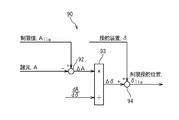
- the limited steering position calculation unit 90 according to the present embodiment includes a subtracter 92, a divider 93, and an adder 94.
- the limited steering position calculation unit 90 according to the present embodiment calculates the limited steering position ⁇ lim without using the specifications B and C.
- the subtractor 92 subtracts the specification A from the predetermined limit value A lim of the specification A to calculate the specification difference value ⁇ A.
- the divider 93 calculates the steering position change amount ⁇ by dividing the specification difference value ⁇ A by the ratio dA / d ⁇ of the change amount of the specification A to the change amount of the steering position ⁇ . In other words, the divider 93 calculates the steering position change amount ⁇ as a product of the reciprocal of the ratio dA / d ⁇ and the specification difference value ⁇ A.
- the adder 94 calculates the limited steering position ⁇ lim by adding the steering position change amount ⁇ to the steering position ⁇ .
- the aircraft control system according to this embodiment is obtained by replacing the limited steering position calculation unit 90 of the aircraft control system according to the first or second embodiment with a limited steering position calculation unit 90 shown in FIG. is there.
- the limited steering position calculation unit 90 according to the present embodiment includes a subtracter 92, a divider 93, an adder 94, and a table 95.
- the table 95 associates the combination of the values of the specifications B and C with the ratio dA / d ⁇ of the change amount of the specification A to the change amount of the steering position ⁇ .
- This embodiment is different from the third embodiment in that the ratio of the change amount of the specification A to the change amount of the steering position ⁇ changes depending on the specifications B and C.
- the subtractor 92 subtracts the specification A from the predetermined limit value A lim of the specification A to calculate the specification difference value ⁇ A.
- the divider 93 calculates the steering position change amount ⁇ by dividing the specification difference value ⁇ A by the ratio dA / d ⁇ based on the table 95. In other words, the divider 93 calculates the steering position change amount ⁇ as a product of the reciprocal of the ratio dA / d ⁇ and the specification difference value ⁇ A based on the table 95.
- the adder 94 calculates the limited steering position ⁇ lim by adding the steering position change amount ⁇ to the steering position ⁇ .
- the method of calculating such a limit steering position [delta] lim is specifications B limit steering position [delta] lim not only specifications A, is effective when also on C.
- the aircraft control system according to the present embodiment is obtained by replacing the limited steering position calculation unit 90 of the aircraft control system according to the first or second embodiment with a limited steering position calculation unit 90 shown in FIG. is there.
- the limited steering position calculation unit 90 according to the present embodiment includes a subtractor 92, a divider 93, an adder 94, a table 95, a differentiator 96, a multiplier 97, and an adder 98.
- the table 95 associates the combination of the values of the specifications B and C with the ratio dA / d ⁇ of the change amount of the specification A to the change amount of the steering position ⁇ .
- This embodiment is different from the fourth embodiment in that the predicted value Ap of the specification A is input to the subtracter 92 instead of the specification A.
- the differentiator 96 differentiates the item A to calculate the item derivative dA / dt.
- the multiplier 97 calculates a specification change amount ⁇ Ap that is a product of the specification differential dA / dt and a predetermined prediction time ⁇ tp.
- the adder 98 adds the specification change amount ⁇ Ap to the specification A, and calculates a specification prediction value Ap as a prediction value after the prediction time ⁇ tp of the specification A.
- the subtracter 92 subtracts the specification predicted value Ap from a predetermined limit value A lim of the specification A to calculate the specification difference value ⁇ A lim .
- the divider 93 calculates the steering position change amount ⁇ by dividing the specification difference value ⁇ A lim by the ratio dA / d ⁇ based on the table 95. In other words, the divider 93 calculates the steering position change amount ⁇ as a product of the reciprocal of the ratio dA / d ⁇ and the specification difference value ⁇ A lim based on the table 95.
- the adder 94 calculates the limited steering position ⁇ lim by adding the steering position change amount ⁇ to the steering position ⁇ . Since the limited steering position ⁇ lim is calculated based on the predicted value Ap of the specification A, the calculation method of the limited steering position ⁇ lim according to the present embodiment is effective when the specification A changes very quickly. .
- the aircraft control system according to this embodiment is obtained by replacing the limited steering position calculation unit 90 of the aircraft control system according to the first or second embodiment with a limited steering position calculation unit 90 shown in FIG. is there.
- the limited steering position calculation unit 90 according to the present embodiment includes a subtractor 92, a divider 93, an adder 94, a table 95, a differentiator 96, a multiplier 97, an adder 98, and a buffer 99. , A subtractor 100, a subtractor 101, and a first-order lag filter 102.
- the transfer function G 102 (s) of the first-order lag filter 102 is expressed by the following equation, where ⁇ is the time constant. (Equation 2)
- the table 95 associates the combination of the values of the specifications B and C with the ratio dA / d ⁇ of the change amount of the specification A to the change amount of the steering position ⁇ .
- This embodiment is different from the fifth embodiment in that a correction value Ac obtained by correcting the predicted value Ap is input to the subtracter 92 instead of the predicted value Ap.
- the differentiator 96 differentiates the item A to calculate the item derivative dA / dt.
- the multiplier 97 calculates a specification change amount ⁇ Ap that is a product of the specification differential dA / dt and a predetermined prediction time ⁇ tp.
- the adder 98 adds the specification change amount ⁇ Ap to the specification A, and calculates a specification prediction value Ap as a prediction value after the prediction time ⁇ tp of the specification A.
- the subtracter 100 calculates a prediction error obtained by subtracting the specification A from the output of the buffer 99 that receives the specification prediction value Ap.
- the holding time of the buffer 99 is the predicted time ⁇ tp.
- the subtractor 101 calculates a specification correction value Ac obtained by subtracting the output of the first-order lag filter 102 that receives the prediction error calculated by the subtracter 100 from the specification prediction value Ap.
- the subtractor 92 subtracts the specification correction value Ac from the predetermined limit value A lim of the specification A to calculate the specification difference value ⁇ A lim .
- the divider 93 calculates the steering position change amount ⁇ by dividing the specification difference value ⁇ A lim by the ratio dA / d ⁇ based on the table 95. In other words, the divider 93 calculates the steering position change amount ⁇ as a product of the reciprocal of the ratio dA / d ⁇ and the specification difference value ⁇ A lim based on the table 95.
- the adder 94 calculates the limited steering position ⁇ lim by adding the steering position change amount ⁇ to the steering position ⁇ . According to the present embodiment, the predicted value Ap of the specification A is corrected based on the prediction error.
- the limited steering position calculation unit 90, the inner loop command calculation unit 110, the reaction force generation command calculation unit 120, the flight control calculation unit 140, and the control surface command calculation unit 150 may be realized as a board on which an electric circuit is mounted.
- the control device 80 or 85 as a computer may be realized by operating based on a computer program.
- the steering position ⁇ of the steering device 10 may be detected using a steering position sensor (not shown) instead of the reaction force generating actuator 20.
Landscapes
- Engineering & Computer Science (AREA)
- Mechanical Engineering (AREA)
- Automation & Control Theory (AREA)
- Aviation & Aerospace Engineering (AREA)
- Control Of Position, Course, Altitude, Or Attitude Of Moving Bodies (AREA)
- Steering Control In Accordance With Driving Conditions (AREA)
- Traffic Control Systems (AREA)
Abstract
パイロットが操縦装置を速く操作した場合であっても飛行状態に関する運用制限の超過が防止される航空機の操縦システム及び航空機の操縦方法を提供する。航空機の操縦システムは、操縦装置と、航空機の飛行状態によって変化する第1諸元を検出するセンサと、第1諸元に基づいて、第1諸元が制限値に達する操縦装置の制限操舵位置を算出する制限操舵位置演算部と、操縦装置の操舵位置と制限操舵位置とに基づいて生成された反力生成コマンドに基づいて、パイロットが操縦装置に対して操舵入力を行うときに受ける反力を変化させる反力生成用アクチュエータと、操舵位置に基づいてインナー・ループ・コマンドを生成するインナー・ループ・コマンド演算部と、操舵位置とインナー・ループ・コマンドとに基づいて、航空機の舵面を駆動する舵面アクチュエータとを備える。
Description
本発明は、航空機の操縦システム及び航空機の操縦方法に関する。
パイロットは、航空機を操縦する際、常時変動する航空機の出力システム及び飛行制御システム等の状態を認識していなければならない。パイロットは、これらシステムの現在の状態だけでなく、それらの作動制限を知っている必要がある。
航空機によっては機構的なばねが用いられ、航空機の作動制限が近づいていることを指摘するために触覚による合図(キュー)が制御レバーを介してパイロットに提供される。そのような機構的なばねは、設定された所定のレベルで連動し、制御に所定の抵抗力を供給する。予め設定されたレベルは一度ばねが取り付けられたら変更不可能である。
特許文献1(特表2004-516970号公報)は、航空機の所定の動的条件に応じて接触力の大きさを変更することが可能であり、且つ機構的なばねを必要としない航空機用出力レバー触覚キューイングシステムを開示している。このシステムにおいては、機構的なばねは、コンピュータ制御されたソフトウエア、可変な磁性粒子摩擦クラッチ、及び電子トリムモータに置き換えられている。触覚警報として出力レバーソフトストップ及び出力レバーバックドライブが用いられている。これらの触覚警報は、出力コマンドが所定の作動限界に達すると、ばね様の触覚キューを提供する。バックドライブコマンドは、航空機及びエンジンの作動状況に基づいて出力レバーを可変の速度でトリムダウンさせる。触覚キューは、航空機及びエンジンが作動制限を超過していない状態になるまで作動したままである。
一方、図1は、インナー・ループ・コマンドを使用する従来の操縦システムを開示している。操縦システムは、操縦装置210と、舵面アクチュエータ230と、スワッシュプレート240と、舵面250と、インナー・ループ・アクチュエータ260と、レート・ジャイロ270と、インナー・ループ・コマンド演算部280を備える。舵面アクチュエータ230は、インナー・ループ・アクチュエータ260を介して操縦装置210に接続され、スワッシュプレート240を介して舵面250に接続されている。舵面アクチュエータ230は、操縦装置210の操舵位置に基づいて舵面を駆動する。ここで、レート・ジャイロ270は、機体の外乱による姿勢変化を検出し、インナー・ループ・コマンド演算部280に出力する。インナー・ループ・コマンド演算部280は姿勢変化に基づいてインナー・ループ・コマンドを出力する。インナー・ループ・コマンドは、舵面アクチュエータ230に与えられるコマンド量をパイロットによる操縦装置210の操舵位置の変化なく増減させるためのコマンドである。インナー・ループ・アクチュエータ260は、インナー・ループ・コマンドに基づいて、舵面アクチュエータ230を介して舵面250を駆動する。したがって、パイロットが細かな修正操舵をせずに操縦装置210の操舵位置を一定に保持した場合であっても、外乱によって機体が不安定になることが防がれる。
本発明の目的は、パイロットが操縦装置を速く操作した場合であっても飛行状態に関する運用制限の超過が防止される航空機の操縦システム及び航空機の操縦方法を提供することである。
本発明による航空機の操縦システムは、操縦装置と、航空機の飛行状態によって変化する第1諸元を検出するセンサと、前記第1諸元に基づいて、前記第1諸元が制限値に達する前記操縦装置の制限操舵位置を算出する制限操舵位置演算部と、前記操縦装置の操舵位置と前記制限操舵位置とに基づいて、反力生成コマンドを生成する反力生成コマンド演算部と、前記反力生成コマンドに基づいて、パイロットが前記操縦装置に対して操舵入力を行うときに受ける反力を変化させる反力生成用アクチュエータと、前記操舵位置に基づいてインナー・ループ・コマンドを生成するインナー・ループ・コマンド演算部と、前記操舵位置と前記インナー・ループ・コマンドとに基づいて、前記航空機の舵面を駆動する舵面アクチュエータと、を具備する。
前記インナー・ループ・コマンド演算部は、前記インナー・ループ・コマンドが前記操舵位置の時間変化率に依存するように前記インナー・ループ・コマンドを生成する。前記舵面アクチュエータは、前記操舵位置が速く変化した場合に前記舵面の駆動量が減少するように前記舵面を駆動する。
上記航空機の操縦システムは、前記インナー・ループ・コマンドに基づいて作動するインナー・ループ・アクチュエータを更に具備する。前記舵面アクチュエータは、前記操舵位置と前記インナー・ループ・アクチュエータの出力変位に基づいて前記舵面を駆動する。
上記航空機の操縦システムは、飛行制御演算部と、舵面コマンド演算部を更に具備する。前記飛行制御演算部は、前記操舵位置に基づいて操舵コマンドを生成する。前記舵面コマンド演算部は、前記操舵コマンドから前記インナー・ループ・コマンドを減算して舵面コマンドを生成する。前記舵面アクチュエータは、前記舵面コマンドに基づいて前記舵面を駆動する。
前記センサは、前記第1諸元を含む複数諸元を検出する。前記複数諸元は前記飛行状態によって変化する。前記制限操舵位置演算部は、前記複数諸元の値の組合せと前記制限操舵位置を対応付けたテーブルに基づいて前記制限操舵位置を算出する。
前記制限操舵位置演算部は、前記制限値と前記第1諸元の差分と、前記操舵位置の変化量に対する前記第1諸元の変化量の割合とに基づいて、操舵位置変化量を算出し、前記操舵位置変化量と、前記操舵位置とに基づいて、前記制限操舵位置を算出する。
前記センサは、前記第1諸元とは異なる複数諸元を更に検出する。前記複数諸元は前記飛行状態によって変化する。前記制限操舵位置演算部は、前記差分と、前記複数諸元と、前記複数諸元の値の組合せと前記割合を対応付けたテーブルとに基づいて、前記操舵位置変化量を算出する。
前記センサは、前記第1諸元とは異なる複数諸元を更に検出する。前記複数諸元は前記飛行状態によって変化する。前記制限操舵位置演算部は、前記第1諸元の所定の予測時間後の予測値としての第1諸元予測値を算出し、前記制限値と前記第1諸元予測値の差分と、前記複数諸元と、前記複数諸元の値の組合せと前記操舵位置の変化量に対する前記第1諸元の変化量の割合とを対応付けたテーブルとに基づいて、操舵位置変化量を算出し、前記操舵位置変化量と、前記操舵位置とに基づいて、前記制限操舵位置を算出する。
前記センサは、前記第1諸元とは異なる複数諸元を更に検出する。前記複数諸元は前記飛行状態によって変化する。前記制限操舵位置演算部は、前記第1諸元の所定の予測時間後の予測値としての第1諸元予測値を算出し、前記第1諸元予測値と、前記第1諸元と、保持時間として前記予測時間が設定されたバッファと、フィルタとに基づいて、前記第1諸元予測値の補正値としての第1諸元補正値を算出し、前記制限値と前記第1諸元補正値の差分と、前記複数諸元と、前記複数諸元の値の組合せと前記操舵位置の変化量に対する前記第1諸元の変化量の割合とを対応付けたテーブルとに基づいて、操舵位置変化量を算出し、前記操舵位置変化量と、前記操舵位置とに基づいて、前記制限操舵位置を算出する。
本発明による航空機の操縦方法は、航空機の飛行状態によって変化する第1諸元を検出するステップと、前記第1諸元に基づいて、前記第1諸元が制限値に達する操縦装置の制限操舵位置を算出するステップと、前記操縦装置の操舵位置と前記制限操舵位置とに基づいて、反力生成コマンドを生成するステップと、前記反力生成コマンドに基づいて、パイロットが前記操縦装置に操舵入力を行うときに受ける反力を変化させるステップと、前記操舵位置に基づいてインナー・ループ・コマンドを生成するステップと、前記操舵位置と前記インナー・ループ・コマンドとに基づいて、前記航空機の舵面を駆動するステップとを具備する。
前記インナー・ループ・コマンドを生成する前記ステップにおいて、前記インナー・ループ・コマンドが前記操舵位置の時間変化率に依存するように前記インナー・ループ・コマンドを生成する。前記舵面を駆動する前記ステップにおいて、前記操舵位置が速く変化した場合に前記舵面の駆動量が減少するように前記舵面を駆動する。
前記操縦装置は、インナー・ループ・アクチュエータ及び舵面アクチュエータを介して前記舵面に接続される。前記舵面を駆動する前記ステップは、前記インナー・ループ・アクチュエータが前記インナー・ループ・コマンドに基づいて作動するステップと、前記舵面アクチュエータが、前記操舵位置及び前記インナー・ループ・アクチュエータの出力変位に基づいて前記舵面を駆動するステップとを含む。
上記航空機の操縦方法は、前記操舵位置に基づいて操舵コマンドを生成するステップと、前記操舵コマンドから前記インナー・ループ・コマンドを減算して舵面コマンドを生成するステップを更に具備する。前記舵面を駆動する前記ステップにおいて、前記舵面コマンドに基づいて前記舵面を駆動する。
前記第1諸元を検出する前記ステップにおいて、前記第1諸元を含む複数諸元を検出する。前記複数諸元は前記飛行状態によって変化する。前記制限操舵位置を算出する前記ステップにおいて、前記複数諸元の値の組合せと前記制限操舵位置を対応付けたテーブルに基づいて前記制限操舵位置を算出する。
前記制限操舵位置を算出する前記ステップは、前記制限値と前記第1諸元の差分と、前記操舵位置の変化量に対する前記第1諸元の変化量の割合とに基づいて、操舵位置変化量を算出するステップと、前記操舵位置変化量と、前記操舵位置とに基づいて、前記制限操舵位置を算出するステップとを含む。
上記航空機の操縦方法は、前記第1諸元とは異なる複数諸元を検出するステップを更に具備する。前記複数諸元は前記飛行状態によって変化する。前記操舵位置変化量を算出する前記ステップにおいて、前記差分と、前記複数諸元と、前記複数諸元の値の組合せと前記割合を対応付けたテーブルとに基づいて、前記操舵位置変化量を算出する。
上記航空機の操縦方法は、前記第1諸元とは異なる複数諸元を検出するステップを更に具備する。前記複数諸元は前記飛行状態によって変化する。前記制限操舵位置を算出する前記ステップは、前記第1諸元の所定の予測時間後の予測値としての第1諸元予測値を算出するステップと、前記制限値と前記第1諸元予測値の差分と、前記複数諸元と、前記複数諸元の値の組合せと前記操舵位置の変化量に対する前記第1諸元の変化量の割合とを対応付けたテーブルとに基づいて、操舵位置変化量を算出するステップと、前記操舵位置変化量と、前記操舵位置とに基づいて、前記制限操舵位置を算出するステップとを含む。
上記航空機の操縦方法は、前記第1諸元とは異なる複数諸元を検出するステップを更に具備する。前記複数諸元は前記飛行状態によって変化する。前記制限操舵位置を算出する前記ステップは、前記第1諸元の所定の予測時間後の予測値としての第1諸元予測値を算出するステップと、前記第1諸元予測値と、前記第1諸元と、保持時間として前記予測時間が設定されたバッファと、フィルタとに基づいて、前記第1諸元予測値の補正値としての第1諸元補正値を算出するステップと、前記制限値と前記第1諸元補正値の差分と、前記複数諸元と、前記複数諸元の値の組合せと前記操舵位置の変化量に対する前記第1諸元の変化量の割合とを対応付けたテーブルとに基づいて、操舵位置変化量を算出するステップと、前記操舵位置変化量と、前記操舵位置とに基づいて、前記制限操舵位置を算出するステップとを含む。
本発明によれば、パイロットが操縦装置を速く操作した場合であっても飛行状態に関する運用制限の超過が防止される航空機の操縦システム及び航空機の操縦方法が提供される。
添付図面を参照して、本発明による航空機の操縦システムを以下に説明する。
(第1の実施形態)
図2を参照して、本発明の第1の実施形態に係る操縦システムを説明する。本実施形態に係る操縦システムは、機力操縦システム(powered flight-control system)であって、ヘリコプタのような航空機に適用される。機力操縦システムは、例えば、ハイドロメカニカル操縦システムである。本実施形態に係る操縦システムは、操縦装置10と、反力生成用アクチュエータ20と、舵面アクチュエータ30と、スワッシュプレート40と、舵面50と、インナー・ループ・アクチュエータ60と、センサ70と、制御装置80を備える。制御装置80は、制限操舵位置演算部90と、インナー・ループ・コマンド演算部110と、反力生成コマンド演算部120を備える。
図2を参照して、本発明の第1の実施形態に係る操縦システムを説明する。本実施形態に係る操縦システムは、機力操縦システム(powered flight-control system)であって、ヘリコプタのような航空機に適用される。機力操縦システムは、例えば、ハイドロメカニカル操縦システムである。本実施形態に係る操縦システムは、操縦装置10と、反力生成用アクチュエータ20と、舵面アクチュエータ30と、スワッシュプレート40と、舵面50と、インナー・ループ・アクチュエータ60と、センサ70と、制御装置80を備える。制御装置80は、制限操舵位置演算部90と、インナー・ループ・コマンド演算部110と、反力生成コマンド演算部120を備える。
操縦装置10は、インナー・ループ・アクチュエータ60、舵面アクチュエータ30、及びスワッシュプレート(swashplate)40を介して舵面50に接続されている。インナー・ループ・アクチュエータ60は、第1部分61と、第2部分62を備える。舵面アクチュエータ30は、入力部31と、出力部32を備える。第1部分61は、操縦装置10に接続されている。第2部分62は、入力部31に接続されている。出力部32は、スワッシュプレート40を介して舵面50に接続されている。
センサ70は、航空機の飛行状態によって変化する少なくとも機体運動の諸元を検出し、検出した諸元を示す諸元信号を制御装置80に出力する。反力生成用アクチュエータ20は、操縦装置10の操舵位置を検出し、検出した操舵位置を示す操舵位置信号を制御装置80に出力する。制御装置80は、インナー・ループ・コマンドをインナー・ループ・アクチュエータ60に出力し、反力生成コマンドを反力生成用アクチュエータ20に出力する。インナー・ループ・アクチュエータ60は、インナー・ループ・コマンドに基づいて作動する。より具体的には、第1部分61に対する第2部分62の相対位置がインナー・ループ・コマンドに基づいて変化する。第1部分61に対する第2部分62の相対位置は、インナー・ループ・アクチュエータ60の出力変位と称される場合がある。反力生成用アクチュエータ20は、反力生成コマンドに基づいて、パイロットが操縦装置10に対して操舵入力を行うときに受ける反力を変化させる。
図3は、本実施形態に係る操縦システムのブロック図を示している。操縦装置10の操舵位置δは、パイロットの操舵入力によって変化する。インナー・ループ・コマンド演算部110は、操舵位置δを示す操舵位置信号に基づいて、インナー・ループ・コマンドを生成する。
図4を参照して、インナー・ループ・コマンド演算部110は、ハイパスフィルタ111を備える。インナー・ループ・コマンドは、操舵位置δを示す操舵位置信号を入力とするハイパスフィルタ111の出力に相当する。より具体的には、インナー・ループ・コマンドは、操舵位置信号を入力とする伝達関数G111(s)の出力にゲインKを乗算して得られる。伝達関数G111(s)は、時定数をτとすると、下記式(1)で表される。このように、操舵位置δの時間変化率に依存するインナー・ループ・コマンドが生成される。
(数1)

(数1)
図3を参照して、インナー・ループ・アクチュエータ60は、インナー・ループ・コマンドに基づいて作動し、これによりインナー・ループ・アクチュエータ60の出力変位が変化する。第2部分62の位置は、インナー・ループ・コマンドに基づくインナー・ループ・アクチュエータ60の出力変位が第1部分61の位置に減算的に合成されて決定される。舵面アクチュエータ30は、操舵コマンドとしての第2部分62の位置に基づいて舵面50を駆動する。第1部分61が操舵位置δに連動しているため、舵面アクチュエータ30は、操舵位置δとインナー・ループ・アクチュエータ60の出力変位に基づいて、舵面50を駆動する。すなわち、舵面アクチュエータ30は、操舵位置δ及びインナー・ループ・コマンドに基づいて舵面50を駆動する。
センサ70は、航空機の飛行状態によって変化する機体運動の諸元を検出し、検出した諸元を示す諸元信号を出力する。ここで、諸元は、エンジントルク、バンク角、前進速度、横方向の速度、メインロータの回転数等である。本実施形態では、センサ70は、複数の諸元A~Cを検出する。ここで、諸元Aは、舵面50の影響を受ける。制限操舵位置演算部90は、諸元A~Cを示す諸元信号に基づいて、諸元Aが制限値に達する操縦装置10の制限操舵位置δlimを算出する。
図5を参照して、制限操舵位置演算部90は、諸元A~Cの値の組合せと制限操舵位置δlimとを対応付けたテーブル91を備える。制限操舵位置演算部90は、テーブル91に基づいて制限操舵位置δlimを算出する。このような制限操舵位置δlimの算出方法は、制限操舵位置δlimが諸元Aだけでなく諸元B,Cにも依存する場合に有効である。
図6を参照して、反力生成コマンド演算部120は、操舵位置δを示す操舵位置信号と制限操舵位置δlimとに基づいて、パイロットが操縦装置10から受けるべき反力を示す反力生成コマンドを生成する。反力生成コマンドは、操舵位置δが制限操舵位置δlimの近くで反力が急に大きくなるように生成される。
図3を参照して、反力生成用アクチュエータ20は、反力生成コマンドに基づいて、パイロットが操縦装置10に対して操舵入力を行うときに受ける反力を変化させる。
図7を参照して、本実施形態に係る航空機の操縦システム及び航空機の操縦方法を説明する。図7は、パイロットが操舵入力により、時刻tより前は操舵位置δを一定に保持し、時刻tにおいて操舵位置δを制限操舵位置δlimまで速く変化(増加)させてその後一定に保持した場合において、操舵位置δ、インナー・ループ・コマンド、操舵コマンド、及び、舵面50の影響を受ける諸元Aの変化を示す。本実施形態においては、操舵コマンドは第2部分62の位置である。
パイロットは、操縦装置10から受ける反力の変化に基づいて制限操舵位置δlimを認識し、操舵位置δが制限操舵位置δlimに達した後は、操舵位置δを制限操舵位置δlimに保持する。
インナー・ループ・コマンドは、時刻tより前は一定値(例えばゼロ)に保持され、時刻tにおいて速く変化(増加)した後、時刻tより前の値に向かって漸近する。
インナー・ループ・コマンドに基づくインナー・ループ・アクチュエータ60の出力変位が第1部分61の位置に減算的に合成されて決定されるため、第2部分62の位置としての操舵コマンドは、時刻tより前は一定に保持され、時刻t以後に制限操舵位置δlimに対応する位置まで変化した後、制限操舵位置δlimに対応する位置に保持される。ここで、第2部分62の位置の時刻t以後における変化は、時刻tにおける操舵位置δの変化に比べると緩やかである。
諸元Aは、時刻tより前は一定値に保持され、時刻t以後に制限値まで変化してその後制限値で一定に保持される。本実施形態においては、操舵位置δに基づくインナー・ループ・コマンドに基づいて舵面アクチュエータ30が舵面50を駆動する。例えば、操舵位置δの時間変化率に依存するインナー・ループ・コマンドに基づいて、操舵位置δが速く変化した場合に舵面50の駆動量が減少するように、舵面アクチュエータ30が舵面50を駆動する。そのため、諸元Aが過渡応答において制限値を超過することが防止される。本実施形態においては、パイロットが反力変化に基づいて操縦装置10の操舵位置δを制限操舵位置δlimに保持するため、諸元Aが定常応答において制限値で一定に保持される。諸元Aが過渡応答において制限値を超過することが防止されるため、航空機が不安定になることが防止される。更に、諸元Aが定常応答において制限値で一定に保持されるため、航空機の性能を最大限生かした操縦が可能となる。
なお、上述の効果と同様の効果が得られるのであれば、図4に示されるアルゴリズムとは異なるアルゴリズムによりインナー・ループ・コマンドを生成してもよい。
上述の効果をより明らかにするために、図8を参照して、第1比較例における操舵位置δ、第2部分62の位置としての操舵コマンド、及び、舵面50の影響を受ける諸元Aの変化を説明する。第1比較例においては、インナー・ループ・コマンドが無効にされて第2部分62の第1部分61に対する相対位置が固定される。操舵位置δは、図7の場合と同様に変化する。第2部分62の第1部分61に対する相対位置が固定されているため、第2部分62の位置は操舵位置δに連動する。したがって、第2部分62の位置としての操舵コマンドは、時刻tより前は一定に保持され、時刻tにおいてある位置まで速く変化してその後はその位置で一定に保持される。諸元Aは、時刻tより前は一定値に保持され、時刻tにおいて急に変化して制限値を一時的に超過して最大値をとった後、制限値まで減少して制限値で一定に保持される。第1比較例においては、諸元Aが過渡応答において制限値を超過するため、航空機が不安定になる。
上述の効果をより明らかにするために、図9を参照して、第2比較例における操舵位置δ、第2部分62の位置としての操舵コマンド、及び、舵面50の影響を受ける諸元Aの変化を説明する。第2比較例においては、インナー・ループ・コマンドが無効にされて第2部分62の第1部分61に対する相対位置が固定され、且つ、制限操舵位置算出部90が制限操舵位置δlimのかわりに制限操舵位置δlim’を算出する。ここで、制限操舵位置δlim’は、諸元Aが過渡応答の最大値において制限値を超過しないように設定されている。この場合、パイロットが操舵入力により、時刻tより前は操舵位置δを一定に保持し、時刻tにおいて操舵位置δを制限操舵位置δlim’まで速く変化させてその後一定に保持する。第2部分62の第1部分61に対する相対位置が固定されているため、第2部分62の位置は操舵位置δに連動する。したがって、第2部分62の位置としての操舵コマンドは、時刻tより前は一定に保持され、時刻tにおいてある位置まで速く変化してその後はその位置で一定に保持される。図9に示された操舵コマンドの時刻tにおける変化量は、図8に示された操舵コマンドの時刻tにおける変化量より小さい。諸元Aは、時刻tより前は一定値に保持され、時刻tにおいて急に変化して制限値の近傍まで達した後、時刻tより前の一定値に向かって少し戻った値で一定に保持される。第2比較例においては、諸元Aが定常応答において制限値からずれた値で一定に保持されるため、航空機の性能を最大限生かした操縦が実現されない。このように、図8に示される例では、諸元の制限値を超えるオーバーシュートが発生している。図9に示される例でも、諸元の制限値を超えるオーバーシュートと同様の変化を発生している。しかしながら、本願発明では、オーバーシュート形状の変化は発生せず、漸近的に制限値に近づいている。
(第2の実施形態)
図10を参照して、本発明の第2の実施形態に係る操縦システムを説明する。本実施形態に係る操縦システムは、フライ・バイ・ワイヤ操縦システムであって、ヘリコプタのような航空機に適用される。本実施形態に係る操縦システムは、操縦装置10と、反力生成用アクチュエータ20と、舵面アクチュエータ35と、スワッシュプレート40と、舵面50と、センサ70と、制御装置85を備える。制御装置85は、制限操舵位置演算部90と、インナー・ループ・コマンド演算部110と、反力生成コマンド演算部120と、飛行制御演算部140と、舵面コマンド演算部150を備える。
図10を参照して、本発明の第2の実施形態に係る操縦システムを説明する。本実施形態に係る操縦システムは、フライ・バイ・ワイヤ操縦システムであって、ヘリコプタのような航空機に適用される。本実施形態に係る操縦システムは、操縦装置10と、反力生成用アクチュエータ20と、舵面アクチュエータ35と、スワッシュプレート40と、舵面50と、センサ70と、制御装置85を備える。制御装置85は、制限操舵位置演算部90と、インナー・ループ・コマンド演算部110と、反力生成コマンド演算部120と、飛行制御演算部140と、舵面コマンド演算部150を備える。
舵面アクチュエータ35は、スワッシュプレート40を介して舵面50に接続されている。
センサ70は、航空機の飛行状態によって変化する機体運動の諸元を検出し、検出した諸元を示す諸元信号を制御装置85に出力する。反力生成用アクチュエータ20は、操縦装置10の操舵位置を検出し、検出した操舵位置を示す操舵位置信号を制御装置85に出力する。制御装置85は、反力生成コマンドを反力生成用アクチュエータ20に出力し、電気信号又は光信号としての舵面コマンドを舵面アクチュエータ35に出力する。反力生成用アクチュエータ20は、反力生成コマンドに基づいて、パイロットが操縦装置10に対して操舵入力を行うときに受ける反力を変化させる。舵面アクチュエータ35は、舵面コマンドに基づいて、スワッシュプレート40を介して舵面50を駆動する。
図11は、本実施形態に係る操縦システムのブロック図を示している。操縦装置10の操舵位置δは、パイロットの操舵入力によって変化する。インナー・ループ・コマンド演算部110は、第1の実施形態と同様に構成される。インナー・ループ・コマンド演算部110は、第1の実施形態と同様に、操舵位置δを示す操舵位置信号に基づいて、インナー・ループ・コマンドを生成する。
飛行制御演算部140は、操舵位置δに基づいて操舵コマンドを生成する。舵面コマンド演算部150は、例えば減算器である。舵面コマンド演算部150は、操舵コマンドからインナー・ループ・コマンドを減算して舵面コマンドを生成する。舵面アクチュエータ35は、舵面コマンドに基づいて舵面50を駆動する。すなわち、舵面アクチュエータ35は、操舵コマンド及びインナー・ループ・コマンドに基づいて舵面50を駆動する。
センサ70は、第1の実施形態と同様に構成される。センサ70は、第1の実施形態と同様に、複数の諸元A~Cを検出し、検出した諸元を示す諸元信号を出力する。制限操舵位置演算部90は、第1の実施形態と同様に構成される。制限操舵位置演算部90は、第1の実施形態と同様に、諸元A~Cを示す諸元信号に基づいて、諸元Aが制限値に達する操縦装置10の制限操舵位置δlimを算出する。
反力生成コマンド演算部120は、第1の実施形態と同様に構成される。反力生成コマンド演算部120は、第1の実施形態と同様に、操舵位置δを示す操舵位置信号と制限操舵位置δlimとに基づいて、パイロットが操縦装置10から受けるべき反力を示す反力生成コマンドを生成する。反力生成コマンドは、操舵位置δが制限操舵位置δlimの近くで反力が急に大きくなるように生成される。
反力生成用アクチュエータ20は、第1の実施形態と同様に、反力生成コマンドに基づいて、パイロットが操縦装置10に対して操舵入力を行うときに受ける反力を変化させる。
図16を参照して、本実施形態に係る航空機の操縦システム及び航空機の操縦方法の効果を説明する。図16は、パイロットが操舵入力により、時刻tより前は操舵位置δを一定に保持し、時刻tにおいて操舵位置δを制限操舵位置δlimまで速く変化(増加)させてその後一定に保持した場合において、操舵位置δ、操舵コマンド、インナー・ループ・コマンド、電気信号又は光信号としての舵面コマンド、及び、舵面50の影響を受ける諸元Aの変化を示す。
パイロットは、操縦装置10から受ける反力の変化に基づいて制限操舵位置δlimを認識し、操舵位置δが制限操舵位置δlimに達した後は、操舵位置δを制限操舵位置δlimに保持する。
操舵コマンドは、操舵位置δと同様に変化する。すなわち、操舵コマンドは、時刻tより前は一定に保持され、時刻tにおいて制限操舵位置δlimに対応する値まで速く変化(増加)し、その後制限操舵位置δlimに対応する値で一定に保持される。
インナー・ループ・コマンドは、時刻tより前は一定値(例えばゼロ)に保持され、時刻tにおいて速く変化(増加)した後、時刻tより前の値に向かって漸近する。
操舵コマンドからインナー・ループ・コマンドを減算して舵面コマンドが生成されるため、舵面コマンドは、時刻tより前は一定に保持され、時刻t以後に制限操舵位置δlimに対応する値まで変化した後、制限操舵位置δlimに対応する値に保持される。ここで、舵面コマンドの時刻t以後における変化は、時刻tにおける操舵位置δや操舵コマンドの変化に比べると緩やかである。
諸元Aは、時刻tより前は一定値に保持され、時刻t以後に制限値まで変化してその後制限値で一定に保持される。本実施形態においては、操舵位置δに基づくインナー・ループ・コマンドに基づいて舵面アクチュエータ35が舵面50を駆動する。例えば、操舵位置δの時間変化率に依存するインナー・ループ・コマンドに基づいて、操舵位置δが速く変化した場合に舵面50の駆動量が減少するように、舵面アクチュエータ35が舵面50を駆動する。そのため、諸元Aが過渡応答において制限値を超過することが防止される。本実施形態においては、パイロットが反力変化に基づいて操縦装置10の操舵位置δを制限操舵位置δlimに保持するため、諸元Aが定常応答において制限値で一定に保持される。諸元Aが過渡応答において制限値を超過することが防止されるため、航空機が不安定になることが防止される。更に、諸元Aが定常応答において制限値で一定に保持されるため、航空機の性能を最大限生かした操縦が可能となる。
(第3の実施形態)
図12を参照して、本発明の第3の実施形態に係る航空機の操縦システムを説明する。本実施形態に係る航空機の操縦システムは、第1又は第2の実施形態に係る航空機の操縦システムの制限操舵位置演算部90が、図12に示す制限操舵位置演算部90で置き換えられたものである。本実施形態に係る制限操舵位置演算部90は、減算器92と、除算器93と、加算器94とを備える。本実施形態に係る制限操舵位置演算部90は、諸元B、Cを用いないで制限操舵位置δlimを算出する。
図12を参照して、本発明の第3の実施形態に係る航空機の操縦システムを説明する。本実施形態に係る航空機の操縦システムは、第1又は第2の実施形態に係る航空機の操縦システムの制限操舵位置演算部90が、図12に示す制限操舵位置演算部90で置き換えられたものである。本実施形態に係る制限操舵位置演算部90は、減算器92と、除算器93と、加算器94とを備える。本実施形態に係る制限操舵位置演算部90は、諸元B、Cを用いないで制限操舵位置δlimを算出する。
減算器92は、諸元Aの所定の制限値Alimから諸元Aを減算して諸元差分値ΔAを算出する。除算器93は、操舵位置δの変化量に対する諸元Aの変化量の割合dA/dδで諸元差分値ΔAを除して操舵位置変化量Δδを算出する。言い換えると、除算器93は、割合dA/dδの逆数と諸元差分値ΔAとの積としての操舵位置変化量Δδを算出する。加算器94は、操舵位置δに操舵位置変化量Δδを加算して制限操舵位置δlimを算出する。
(第4の実施形態)
図13を参照して、本発明の第4の実施形態に係る航空機の操縦システムを説明する。本実施形態に係る航空機の操縦システムは、第1又は第2の実施形態に係る航空機の操縦システムの制限操舵位置演算部90が、図13に示す制限操舵位置演算部90で置き換えられたものである。本実施形態に係る制限操舵位置演算部90は、減算器92と、除算器93と、加算器94と、テーブル95を備える。テーブル95は、諸元B、Cの値の組合せと操舵位置δの変化量に対する諸元Aの変化量の割合dA/dδとを対応付けている。本実施形態においては、操舵位置δの変化量に対する諸元Aの変化量の割合が諸元B、Cによって変化する点が第3の実施形態と異なる。
図13を参照して、本発明の第4の実施形態に係る航空機の操縦システムを説明する。本実施形態に係る航空機の操縦システムは、第1又は第2の実施形態に係る航空機の操縦システムの制限操舵位置演算部90が、図13に示す制限操舵位置演算部90で置き換えられたものである。本実施形態に係る制限操舵位置演算部90は、減算器92と、除算器93と、加算器94と、テーブル95を備える。テーブル95は、諸元B、Cの値の組合せと操舵位置δの変化量に対する諸元Aの変化量の割合dA/dδとを対応付けている。本実施形態においては、操舵位置δの変化量に対する諸元Aの変化量の割合が諸元B、Cによって変化する点が第3の実施形態と異なる。
減算器92は、諸元Aの所定の制限値Alimから諸元Aを減算して諸元差分値ΔAを算出する。除算器93は、テーブル95に基づいて、割合dA/dδで諸元差分値ΔAを除して操舵位置変化量Δδを算出する。言い換えると、除算器93は、テーブル95に基づいて、割合dA/dδの逆数と諸元差分値ΔAとの積としての操舵位置変化量Δδを算出する。加算器94は、操舵位置δに操舵位置変化量Δδを加算して制限操舵位置δlimを算出する。このような制限操舵位置δlimの算出方法は、制限操舵位置δlimが諸元Aだけでなく諸元B,Cにも依存する場合に有効である。
(第5の実施形態)
図14を参照して、本発明の第5の実施形態に係る航空機の操縦システムを説明する。本実施形態に係る航空機の操縦システムは、第1又は第2の実施形態に係る航空機の操縦システムの制限操舵位置演算部90が、図14に示す制限操舵位置演算部90で置き換えられたものである。本実施形態に係る制限操舵位置演算部90は、減算器92と、除算器93と、加算器94と、テーブル95と、微分器96と、乗算器97と、加算器98を備える。テーブル95は、諸元B、Cの値の組合せと操舵位置δの変化量に対する諸元Aの変化量の割合dA/dδとを対応付けている。本実施形態においては、諸元Aのかわりに諸元Aの予測値Apが減算器92に入力される点が第4の実施形態と異なる。
図14を参照して、本発明の第5の実施形態に係る航空機の操縦システムを説明する。本実施形態に係る航空機の操縦システムは、第1又は第2の実施形態に係る航空機の操縦システムの制限操舵位置演算部90が、図14に示す制限操舵位置演算部90で置き換えられたものである。本実施形態に係る制限操舵位置演算部90は、減算器92と、除算器93と、加算器94と、テーブル95と、微分器96と、乗算器97と、加算器98を備える。テーブル95は、諸元B、Cの値の組合せと操舵位置δの変化量に対する諸元Aの変化量の割合dA/dδとを対応付けている。本実施形態においては、諸元Aのかわりに諸元Aの予測値Apが減算器92に入力される点が第4の実施形態と異なる。
微分器96は、諸元Aを微分して諸元微分dA/dtを算出する。乗算器97は、諸元微分dA/dtと所定の予測時間Δtpとの積である諸元変化量ΔApを算出する。加算器98は、諸元Aに諸元変化量ΔApを加算して、諸元Aの予測時間Δtp後の予測値としての諸元予測値Apを算出する。減算器92は、諸元Aの所定の制限値Alimから諸元予測値Apを減算して諸元差分値ΔAlimを算出する。除算器93は、テーブル95に基づいて、割合dA/dδで諸元差分値ΔAlimを除して操舵位置変化量Δδを算出する。言い換えると、除算器93は、テーブル95に基づいて、割合dA/dδの逆数と諸元差分値ΔAlimとの積としての操舵位置変化量Δδを算出する。加算器94は、操舵位置δに操舵位置変化量Δδを加算して制限操舵位置δlimを算出する。諸元Aの予測値Apに基づいて制限操舵位置δlimが算出されるため、本実施形態に係る制限操舵位置δlimの算出方法は、諸元Aが非常に速く変化する場合に有効である。
(第6の実施形態)
図15を参照して、本発明の第6の実施形態に係る航空機の操縦システムを説明する。本実施形態に係る航空機の操縦システムは、第1又は第2の実施形態に係る航空機の操縦システムの制限操舵位置演算部90が、図15に示す制限操舵位置演算部90で置き換えられたものである。本実施形態に係る制限操舵位置演算部90は、減算器92と、除算器93と、加算器94と、テーブル95と、微分器96と、乗算器97と、加算器98と、バッファ99と、減算器100と、減算器101と、一次遅れフィルタ102を備える。一次遅れフィルタ102の伝達関数G102(s)は、時定数をτとすると、下記式で表される。
(数2)
 テーブル95は、諸元B、Cの値の組合せと操舵位置δの変化量に対する諸元Aの変化量の割合dA/dδとを対応付けている。本実施形態においては、予測値Apのかわりに予測値Apが補正された補正値Acが減算器92に入力される点が第5の実施形態と異なる。
図15を参照して、本発明の第6の実施形態に係る航空機の操縦システムを説明する。本実施形態に係る航空機の操縦システムは、第1又は第2の実施形態に係る航空機の操縦システムの制限操舵位置演算部90が、図15に示す制限操舵位置演算部90で置き換えられたものである。本実施形態に係る制限操舵位置演算部90は、減算器92と、除算器93と、加算器94と、テーブル95と、微分器96と、乗算器97と、加算器98と、バッファ99と、減算器100と、減算器101と、一次遅れフィルタ102を備える。一次遅れフィルタ102の伝達関数G102(s)は、時定数をτとすると、下記式で表される。
(数2)
微分器96は、諸元Aを微分して諸元微分dA/dtを算出する。乗算器97は、諸元微分dA/dtと所定の予測時間Δtpとの積である諸元変化量ΔApを算出する。加算器98は、諸元Aに諸元変化量ΔApを加算して、諸元Aの予測時間Δtp後の予測値としての諸元予測値Apを算出する。減算器100は、諸元予測値Apを入力とするバッファ99の出力から諸元Aを減算した予測誤差を算出する。ここで、バッファ99の保持時間は予測時間Δtpである。減算器101は、減算器100が算出した予測誤差を入力とする一次遅れフィルタ102の出力を諸元予測値Apから減算した諸元補正値Acを算出する。減算器92は、諸元Aの所定の制限値Alimから諸元補正値Acを減算して諸元差分値ΔAlimを算出する。除算器93は、テーブル95に基づいて、割合dA/dδで諸元差分値ΔAlimを除して操舵位置変化量Δδを算出する。言い換えると、除算器93は、テーブル95に基づいて、割合dA/dδの逆数と諸元差分値ΔAlimとの積としての操舵位置変化量Δδを算出する。加算器94は、操舵位置δに操舵位置変化量Δδを加算して制限操舵位置δlimを算出する。本実施形態によれば、諸元Aの予測値Apが予測誤差に基づいて補正される。
以上、上記各実施形態に係る操縦システムがヘリコプタに適用される場合を説明したが、上記各実施形態に係る操縦システムを固定翼機に適用してもよい。
制限操舵位置演算部90、インナー・ループ・コマンド演算部110、反力生成コマンド演算部120、飛行制御演算部140、及び舵面コマンド演算部150は、電気回路が載ったボードとして実現されてもよく、コンピュータとしての制御装置80又は85がコンピュータプログラムに基づいて動作することで実現されてもよい。
上記各実施形態において、反力生成用アクチュエータ20のかわりに操舵位置センサ(不図示)を用いて操縦装置10の操舵位置δを検出してもよい。
Claims (18)
- 操縦装置と、
航空機の飛行状態によって変化する複数の諸元のうちの少なくとも第1諸元を検出するセンサと、
前記センサの検出結果に基づいて、前記第1諸元が制限値に達する前記操縦装置の制限操舵位置を算出する制限操舵位置演算部と、
前記操縦装置の操舵位置と前記制限操舵位置とに基づいて、反力生成コマンドを生成する反力生成コマンド演算部と、
前記反力生成コマンドに基づいて、前記操縦装置に対して操舵入力を行うときにパイロットが受ける反力を変化させる反力生成用アクチュエータと、
前記操舵位置に基づいてインナー・ループ・コマンドを生成するインナー・ループ・コマンド演算部と、
前記操舵位置と前記インナー・ループ・コマンドとから得られる舵面コマンドに基づいて、前記航空機の舵面を駆動する舵面アクチュエータと、
を具備する
航空機の操縦システム。 - 請求項1の航空機の操縦システムにおいて、
前記インナー・ループ・コマンド演算部は、前記インナー・ループ・コマンドが前記操舵位置の時間変化率に依存するように、また前記舵面の駆動量が減少するように前記インナー・ループ・コマンドを生成する
航空機の操縦システム。 - 請求項2の航空機の操縦システムおいて、
前記インナー・ループ・コマンドに基づいて作動するインナー・ループ・アクチュエータを更に具備し、
前記舵面アクチュエータは、前記操舵位置と前記インナー・ループ・アクチュエータの作動結果としての出力変位とから得られる前記舵面コマンドに基づいて前記舵面を駆動する
航空機の操縦システム。 - 請求項2の航空機の操縦システムにおいて、
飛行制御演算部と、
舵面コマンド演算部と
を更に具備し、
前記飛行制御演算部は、前記操舵位置に基づいて操舵コマンドを生成し、
前記舵面コマンド演算部は、前記操舵コマンドから前記インナー・ループ・コマンドを減算して前記舵面コマンドを生成する
航空機の操縦システム。 - 請求項1乃至4のいずれかに記載の航空機の操縦システムにおいて、
前記センサは、前記複数の諸元を検出し、
前記制限操舵位置演算部は、前記複数の諸元の値の組合せと前記制限操舵位置を対応付けたテーブルに基づいて前記制限操舵位置を算出する
航空機の操縦システム。 - 請求項1乃至4のいずれかに記載の航空機の操縦システムにおいて、
前記制限操舵位置演算部は、
前記制限値と前記第1諸元の差分と、前記操舵位置の変化量に対する前記第1諸元の変化量の割合とに基づいて、操舵位置変化量を算出し、
前記操舵位置変化量と、前記操舵位置とに基づいて、前記制限操舵位置を算出する
航空機の操縦システム。 - 請求項6の航空機の操縦システムにおいて、
前記センサは、前記複数の諸元を検出し、
前記制限操舵位置演算部は、前記差分と、前記複数の諸元と、前記複数の諸元の値の組合せと前記割合を対応付けたテーブルとに基づいて、前記操舵位置変化量を算出する
航空機の操縦システム。 - 請求項1乃至4のいずれかに記載の航空機の操縦システムにおいて、
前記センサは、前記複数の諸元を検出し、
前記制限操舵位置演算部は、
前記第1諸元の所定の予測時間後の予測値としての第1諸元予測値を算出し、
前記制限値と前記第1諸元予測値の差分と、前記複数の諸元と、前記複数の諸元の値の組合せと前記操舵位置の変化量に対する前記第1諸元の変化量の割合とを対応付けたテーブルとに基づいて、操舵位置変化量を算出し、
前記操舵位置変化量と、前記操舵位置とに基づいて、前記制限操舵位置を算出する
航空機の操縦システム。 - 請求項1乃至4のいずれかに記載の航空機の操縦システムにおいて、
前記センサは、前記複数の諸元を検出し、
前記制限操舵位置演算部は、
前記第1諸元の所定の予測時間後の予測値としての第1諸元予測値を算出し、
前記第1諸元予測値と、前記第1諸元と、保持時間として前記予測時間が設定されたバッファと、フィルタとに基づいて、前記第1諸元予測値の補正値としての第1諸元補正値を算出し、
前記制限値と前記第1諸元補正値の差分と、前記複数諸元と、前記複数諸元の値の組合せと前記操舵位置の変化量に対する前記第1諸元の変化量の割合とを対応付けたテーブルとに基づいて、操舵位置変化量を算出し、
前記操舵位置変化量と、前記操舵位置とに基づいて、前記制限操舵位置を算出する
航空機の操縦システム。 - 航空機の飛行状態によって変化する複数の諸元のうちの少なくとも第1諸元をセンサにより検出するステップと、
前記センサの検出結果に基づいて、前記第1諸元が制限値に達する操縦装置の制限操舵位置を算出するステップと、
前記操縦装置の操舵位置と前記制限操舵位置とに基づいて、反力生成コマンドを生成するステップと、
前記反力生成コマンドに基づいて、パイロットが前記操縦装置に操舵入力を行うときに受ける反力を変化させるステップと、
前記操舵位置に基づいてインナー・ループ・コマンドを生成するステップと、
前記操舵位置と前記インナー・ループ・コマンドとから得られる舵面コマンドに基づいて、前記航空機の舵面を駆動するステップと
を具備する
航空機の操縦方法。 - 請求項10の航空機の操縦方法において、
前記インナー・ループ・コマンドを生成する前記ステップは、前記インナー・ループ・コマンドが前記操舵位置の時間変化率に依存するように、また前記舵面の駆動量が減少するように前記インナー・ループ・コマンドを生成するステップを備える
航空機の操縦方法。 - 請求項11の航空機の操縦方法において、
前記操縦装置は、インナー・ループ・アクチュエータ及び舵面アクチュエータを介して前記舵面に接続され、
前記舵面を駆動する前記ステップは、
前記インナー・ループ・コマンドに基づいて前記インナー・ループ・アクチュエータの作動を行うステップと、
前記操舵位置及び前記インナー・ループ・アクチュエータの作動結果としての出力変位とから得られる前記舵面コマンドに基づいて、前記舵面アクチュエータにより前記舵面を駆動するステップと
を備える
航空機の操縦方法。 - 請求項11の航空機の操縦方法において、
前記操舵位置に基づいて、操舵コマンドを生成するステップと、
前記操舵コマンドから前記インナー・ループ・コマンドを減算して前記舵面コマンドを生成するステップを更に具備する
航空機の操縦方法。 - 請求項10乃至13のいずれかに記載の航空機の操縦方法において、
前記検出するステップは、前記複数の諸元を検出するステップを備え、
前記制限操舵位置を算出する前記ステップは、前記複数諸元の値の組合せと前記制限操舵位置を対応付けたテーブルに基づいて前記制限操舵位置を算出するステップを備える
航空機の操縦方法。 - 請求項10乃至13のいずれかに記載の航空機の操縦方法において、
前記制限操舵位置を算出する前記ステップは、
前記制限値と前記第1諸元の差分と、前記操舵位置の変化量に対する前記第1諸元の変化量の割合とに基づいて、操舵位置変化量を算出するステップと、
前記操舵位置変化量と、前記操舵位置とに基づいて、前記制限操舵位置を算出するステップと
を備える
航空機の操縦方法。 - 請求項15の航空機の操縦方法において、
前記検出するステップは、前記複数の諸元を検出するステップを備え、
前記操舵位置変化量を算出する前記ステップは、前記差分と、前記複数諸元と、前記複数諸元の値の組合せと前記割合を対応付けたテーブルとに基づいて、前記操舵位置変化量を算出するステップを備える
航空機の操縦方法。 - 請求項10乃至13のいずれかに記載の航空機の操縦方法において、
前記検出するステップは、前記複数の諸元を検出するステップを備え、
前記制限操舵位置を算出する前記ステップは、
前記第1諸元の所定の予測時間後の予測値としての第1諸元予測値を算出するステップと、
前記制限値と前記第1諸元予測値の差分と、前記複数諸元と、前記複数諸元の値の組合せと前記操舵位置の変化量に対する前記第1諸元の変化量の割合とを対応付けたテーブルとに基づいて、操舵位置変化量を算出するステップと、
前記操舵位置変化量と、前記操舵位置とに基づいて、前記制限操舵位置を算出するステップと
を備える
航空機の操縦方法。 - 請求項10乃至13のいずれかに記載の航空機の操縦方法において、
前記検出するステップは、前記複数の諸元を検出するステップを備え、
前記制限操舵位置を算出する前記ステップは、
前記第1諸元の所定の予測時間後の予測値としての第1諸元予測値を算出するステップと、
前記第1諸元予測値と、前記第1諸元と、保持時間として前記予測時間が設定されたバッファと、フィルタとに基づいて、前記第1諸元予測値の補正値としての第1諸元補正値を算出するステップと、
前記制限値と前記第1諸元補正値の差分と、前記複数諸元と、前記複数諸元の値の組合せと前記操舵位置の変化量に対する前記第1諸元の変化量の割合とを対応付けたテーブルとに基づいて、操舵位置変化量を算出するステップと、
前記操舵位置変化量と、前記操舵位置とに基づいて、前記制限操舵位置を算出するステップと
を備える
航空機の操縦方法。
Priority Applications (2)
| Application Number | Priority Date | Filing Date | Title |
|---|---|---|---|
| US13/388,319 US8655509B2 (en) | 2009-09-14 | 2010-09-14 | Flight control system of aircraft |
| EP10815491.5A EP2479107B1 (en) | 2009-09-14 | 2010-09-14 | Aircraft flight control system |
Applications Claiming Priority (2)
| Application Number | Priority Date | Filing Date | Title |
|---|---|---|---|
| JP2009212256A JP5594996B2 (ja) | 2009-09-14 | 2009-09-14 | 航空機の操縦システム |
| JP2009-212256 | 2009-09-14 |
Publications (1)
| Publication Number | Publication Date |
|---|---|
| WO2011030901A1 true WO2011030901A1 (ja) | 2011-03-17 |
Family
ID=43732563
Family Applications (1)
| Application Number | Title | Priority Date | Filing Date |
|---|---|---|---|
| PCT/JP2010/065780 Ceased WO2011030901A1 (ja) | 2009-09-14 | 2010-09-14 | 航空機の操縦システム |
Country Status (4)
| Country | Link |
|---|---|
| US (1) | US8655509B2 (ja) |
| EP (1) | EP2479107B1 (ja) |
| JP (1) | JP5594996B2 (ja) |
| WO (1) | WO2011030901A1 (ja) |
Families Citing this family (10)
| Publication number | Priority date | Publication date | Assignee | Title |
|---|---|---|---|---|
| JP5791460B2 (ja) | 2011-10-21 | 2015-10-07 | 三菱重工業株式会社 | 航空機及び航空機の制御方法 |
| JP6181942B2 (ja) | 2013-02-28 | 2017-08-16 | 三菱航空機株式会社 | 航空機の警告システム、及び、航空機 |
| US9878776B2 (en) * | 2014-05-15 | 2018-01-30 | The Boeing Company | System and method for optimizing horizontal tail loads |
| CN104731103B (zh) * | 2015-01-21 | 2017-10-03 | 北京航空航天大学 | 一种多层闭环控制策略的Stewart六自由度飞行模拟平台 |
| PL3069990T3 (pl) * | 2015-03-20 | 2017-06-30 | Airbus Helicopters Deutschland GmbH | Urządzenie generujące sztuczne odczucie siły, do systemu sterowania pojazdu, a zwłaszcza statku powietrznego |
| FR3057243B1 (fr) * | 2016-10-12 | 2018-10-05 | Airbus Helicopters | Organe de commande electrique, aeronef a voilure tournante et procede |
| JP6926482B2 (ja) * | 2017-01-13 | 2021-08-25 | オムロン株式会社 | 制御装置、制御方法、制御プログラム |
| US10802482B2 (en) | 2017-02-27 | 2020-10-13 | Textron Innovations Inc. | Reverse tactile cue for rotorcraft rotor overspeed protection |
| US20220350347A1 (en) * | 2021-04-30 | 2022-11-03 | Bell Textron Inc. | Nested-loop model-following control law |
| US20250242908A1 (en) * | 2024-01-29 | 2025-07-31 | Textron Innovations Inc. | Rotorcraft system for command mode transitions |
Citations (5)
| Publication number | Priority date | Publication date | Assignee | Title |
|---|---|---|---|---|
| JPH0437838Y2 (ja) * | 1987-01-22 | 1992-09-04 | ||
| JPH0641279B2 (ja) * | 1981-03-30 | 1994-06-01 | ユナイテッド・テクノロジ−ズ・コ−ポレイション | 航空機の自動操縦装置 |
| JPH078679B2 (ja) * | 1983-03-17 | 1995-02-01 | ハネウェル・インコーポレーテッド | 航空機用自動飛行制御装置 |
| JP2004516970A (ja) | 2000-05-16 | 2004-06-10 | ベル ヘリコプター テクストロン インコーポレイテッド | 出力レバー触覚キューイングシステム |
| JP4198668B2 (ja) * | 2004-11-11 | 2008-12-17 | 川崎重工業株式会社 | 航空機の旋回経路生成方法および装置 |
Family Cites Families (21)
| Publication number | Priority date | Publication date | Assignee | Title |
|---|---|---|---|---|
| US3493826A (en) * | 1965-09-13 | 1970-02-03 | Honeywell Inc | Servomechanism including a lead network feedback and means to modify the lead network responsive to rate |
| US4279391A (en) * | 1979-01-24 | 1981-07-21 | United Technologies Corporation | Desensitizing helicopter control response to inadvertent pilot inputs |
| US4599698A (en) * | 1983-05-02 | 1986-07-08 | United Technologies Corporation | Aircraft trim actuator shutdown monitor system and method |
| JPH031819A (ja) | 1989-05-30 | 1991-01-08 | Matsushita Electric Ind Co Ltd | 炊飯器 |
| JP2760584B2 (ja) | 1989-07-14 | 1998-06-04 | 三洋電機株式会社 | 非水系電解液電池 |
| JP2539047B2 (ja) | 1989-08-02 | 1996-10-02 | 株式会社東芝 | 位置合せ方法 |
| DE3928331A1 (de) | 1989-08-26 | 1991-02-28 | Agfa Gevaert Ag | Gegenstromschlussbehandlungsvorrichtung |
| JP2678809B2 (ja) | 1990-06-04 | 1997-11-19 | 富士写真フイルム株式会社 | ハロゲン化銀写真乳剤の製造方法 |
| MY108621A (en) | 1990-08-01 | 1996-10-31 | Novartis Ag | Polylactide preparation and purification |
| JP2824905B2 (ja) | 1990-11-29 | 1998-11-18 | 敬 高橋 | 可撓性生地を使用した流下式太陽集熱器およびこの流下式太陽集熱器の支持方法 |
| JP3246089B2 (ja) | 1993-06-24 | 2002-01-15 | 松下電器産業株式会社 | 全自動洗濯機 |
| JP3001819B2 (ja) * | 1996-11-21 | 2000-01-24 | 株式会社コミュータヘリコプタ先進技術研究所 | 飛行領域逸脱の警告方法および装置 |
| JP3046771B2 (ja) * | 1996-12-19 | 2000-05-29 | 株式会社コミュータヘリコプタ先進技術研究所 | 操縦装置 |
| US5853152A (en) * | 1997-04-29 | 1998-12-29 | Sikorsky Aircraft Corporation | Collective detent system for vertical takeoff flight operations |
| JP3065603B1 (ja) * | 1999-03-18 | 2000-07-17 | 株式会社コミュータヘリコプタ先進技術研究所 | 操縦装置 |
| JP3091743B1 (ja) | 1999-03-30 | 2000-09-25 | 株式会社コミュータヘリコプタ先進技術研究所 | 操縦装置 |
| US6695264B2 (en) | 2000-05-16 | 2004-02-24 | Bell Helicopter Textron, Inc. | Power lever tactile cueing system |
| EP1485892B1 (en) * | 2002-03-21 | 2012-10-17 | Bell Helicopter Textron Inc. | Method and apparatus for tactile cueing of aircraft controls |
| US6885917B2 (en) * | 2002-11-07 | 2005-04-26 | The Boeing Company | Enhanced flight control systems and methods for a jet powered tri-mode aircraft |
| US8165733B2 (en) * | 2007-09-04 | 2012-04-24 | Embraer S.A. | Stall, buffeting, low speed and high attitude protection system |
| US20090187292A1 (en) * | 2008-01-17 | 2009-07-23 | Mark Andrew Hreha | Integrated pitch, roll, and yaw inceptor |
-
2009
- 2009-09-14 JP JP2009212256A patent/JP5594996B2/ja active Active
-
2010
- 2010-09-14 WO PCT/JP2010/065780 patent/WO2011030901A1/ja not_active Ceased
- 2010-09-14 US US13/388,319 patent/US8655509B2/en active Active
- 2010-09-14 EP EP10815491.5A patent/EP2479107B1/en not_active Not-in-force
Patent Citations (5)
| Publication number | Priority date | Publication date | Assignee | Title |
|---|---|---|---|---|
| JPH0641279B2 (ja) * | 1981-03-30 | 1994-06-01 | ユナイテッド・テクノロジ−ズ・コ−ポレイション | 航空機の自動操縦装置 |
| JPH078679B2 (ja) * | 1983-03-17 | 1995-02-01 | ハネウェル・インコーポレーテッド | 航空機用自動飛行制御装置 |
| JPH0437838Y2 (ja) * | 1987-01-22 | 1992-09-04 | ||
| JP2004516970A (ja) | 2000-05-16 | 2004-06-10 | ベル ヘリコプター テクストロン インコーポレイテッド | 出力レバー触覚キューイングシステム |
| JP4198668B2 (ja) * | 2004-11-11 | 2008-12-17 | 川崎重工業株式会社 | 航空機の旋回経路生成方法および装置 |
Also Published As
| Publication number | Publication date |
|---|---|
| EP2479107A4 (en) | 2017-03-01 |
| JP2011057178A (ja) | 2011-03-24 |
| EP2479107A1 (en) | 2012-07-25 |
| US20120130565A1 (en) | 2012-05-24 |
| US8655509B2 (en) | 2014-02-18 |
| JP5594996B2 (ja) | 2014-09-24 |
| EP2479107B1 (en) | 2018-05-30 |
Similar Documents
| Publication | Publication Date | Title |
|---|---|---|
| JP5594996B2 (ja) | 航空機の操縦システム | |
| CN109572803B (zh) | 车辆用控制装置 | |
| CN102712359B (zh) | 用于有人驾驶飞行器的控制系统的响应模式 | |
| CN108536159B (zh) | 旋翼飞行器控制模式转换平滑 | |
| US8025256B2 (en) | Precision adjust split detent for a vehicle | |
| EP3517408B1 (en) | Steering control device | |
| US20050080495A1 (en) | Apparatus and method for controlling a force-activated controller | |
| CN101939187A (zh) | 失速、抖振、低速和高姿态保护系统 | |
| EP3442861B1 (en) | Control systems and methods | |
| WO2016152746A1 (ja) | 電動ブレーキ装置 | |
| WO2013058171A1 (ja) | 航空機及び航空機の制御方法 | |
| CN108502153A (zh) | Fbw飞行控制系统、方法及旋翼飞行器 | |
| EP3613671B1 (en) | Rotorcraft control mode transition smoothing | |
| EP3882134B1 (en) | Cockpit inceptor system | |
| JP7050624B2 (ja) | モータ制御装置及びこれを備えた電動ブレーキ装置 | |
| US8219909B2 (en) | Human-machine interface with integrated position sensors and passive haptic feedback devices | |
| US9776708B2 (en) | Method of managing discontinuities in vehicle control following a control transition, and a vehicle | |
| US20200290728A1 (en) | Variable operator interface for backdriving control input devices | |
| US10421536B2 (en) | Method of controlling an electrical taxiing system | |
| CN112306074B (zh) | 一种用于自动驾驶仪的超控断开装置和超控断开方法 | |
| US20250132712A1 (en) | Control systems and methods with haptic feedback | |
| CN120288234A (zh) | 飞机飞行控制件 | |
| US20150066251A1 (en) | Flutter control actuator | |
| KR20150088476A (ko) | 조이스틱을 이용한 스러스터 토크 제어장치 및 방법 |
Legal Events
| Date | Code | Title | Description |
|---|---|---|---|
| 121 | Ep: the epo has been informed by wipo that ep was designated in this application |
Ref document number: 10815491 Country of ref document: EP Kind code of ref document: A1 |
|
| WWE | Wipo information: entry into national phase |
Ref document number: 13388319 Country of ref document: US |
|
| WWE | Wipo information: entry into national phase |
Ref document number: 2010815491 Country of ref document: EP |
|
| NENP | Non-entry into the national phase |
Ref country code: DE |