WO2011033552A1 - 煙感知器 - Google Patents
煙感知器 Download PDFInfo
- Publication number
- WO2011033552A1 WO2011033552A1 PCT/JP2009/004602 JP2009004602W WO2011033552A1 WO 2011033552 A1 WO2011033552 A1 WO 2011033552A1 JP 2009004602 W JP2009004602 W JP 2009004602W WO 2011033552 A1 WO2011033552 A1 WO 2011033552A1
- Authority
- WO
- WIPO (PCT)
- Prior art keywords
- light receiving
- smoke
- light
- unit
- output
- Prior art date
- Legal status (The legal status is an assumption and is not a legal conclusion. Google has not performed a legal analysis and makes no representation as to the accuracy of the status listed.)
- Ceased
Links
Images



Classifications
-
- G—PHYSICS
- G08—SIGNALLING
- G08B—SIGNALLING SYSTEMS, e.g. PERSONAL CALLING SYSTEMS; ORDER TELEGRAPHS; ALARM SYSTEMS
- G08B17/00—Fire alarms; Alarms responsive to explosion
- G08B17/10—Actuation by presence of smoke or gases, e.g. automatic alarm devices for analysing flowing fluid materials by the use of optical means
- G08B17/103—Actuation by presence of smoke or gases, e.g. automatic alarm devices for analysing flowing fluid materials by the use of optical means using a light emitting and receiving device
- G08B17/107—Actuation by presence of smoke or gases, e.g. automatic alarm devices for analysing flowing fluid materials by the use of optical means using a light emitting and receiving device for detecting light-scattering due to smoke
-
- G—PHYSICS
- G01—MEASURING; TESTING
- G01N—INVESTIGATING OR ANALYSING MATERIALS BY DETERMINING THEIR CHEMICAL OR PHYSICAL PROPERTIES
- G01N21/00—Investigating or analysing materials by the use of optical means, i.e. using sub-millimetre waves, infrared, visible or ultraviolet light
- G01N21/17—Systems in which incident light is modified in accordance with the properties of the material investigated
- G01N21/47—Scattering, i.e. diffuse reflection
- G01N21/49—Scattering, i.e. diffuse reflection within a body or fluid
- G01N21/53—Scattering, i.e. diffuse reflection within a body or fluid within a flowing fluid, e.g. smoke
-
- G—PHYSICS
- G01—MEASURING; TESTING
- G01N—INVESTIGATING OR ANALYSING MATERIALS BY DETERMINING THEIR CHEMICAL OR PHYSICAL PROPERTIES
- G01N21/00—Investigating or analysing materials by the use of optical means, i.e. using sub-millimetre waves, infrared, visible or ultraviolet light
- G01N21/17—Systems in which incident light is modified in accordance with the properties of the material investigated
- G01N21/47—Scattering, i.e. diffuse reflection
- G01N2021/4704—Angular selective
- G01N2021/4707—Forward scatter; Low angle scatter
-
- G—PHYSICS
- G01—MEASURING; TESTING
- G01N—INVESTIGATING OR ANALYSING MATERIALS BY DETERMINING THEIR CHEMICAL OR PHYSICAL PROPERTIES
- G01N21/00—Investigating or analysing materials by the use of optical means, i.e. using sub-millimetre waves, infrared, visible or ultraviolet light
- G01N21/17—Systems in which incident light is modified in accordance with the properties of the material investigated
- G01N21/47—Scattering, i.e. diffuse reflection
- G01N2021/4704—Angular selective
- G01N2021/4709—Backscatter
-
- G—PHYSICS
- G08—SIGNALLING
- G08B—SIGNALLING SYSTEMS, e.g. PERSONAL CALLING SYSTEMS; ORDER TELEGRAPHS; ALARM SYSTEMS
- G08B17/00—Fire alarms; Alarms responsive to explosion
- G08B17/10—Actuation by presence of smoke or gases, e.g. automatic alarm devices for analysing flowing fluid materials by the use of optical means
- G08B17/11—Actuation by presence of smoke or gases, e.g. automatic alarm devices for analysing flowing fluid materials by the use of optical means using an ionisation chamber for detecting smoke or gas
- G08B17/113—Constructional details
Definitions
- the present invention relates to a smoke detection system, a smoke detector, and a receiver that detect a fire by smoke.
- Patent Literature 1 discloses a smoke detector using a plurality of light emitting elements having different wavelengths. This smoke detector is directed to an environment where smoke may be present.
- a light emitting element that emits light having a relatively short wavelength for example, a blue light emitting diode LED
- a light emitting element that emits light having a relatively long wavelength for example, a light emitting element
- the smoke detector causes the light emitting elements to emit light alternately at different timings, obtains the amount of light received from the light receiving element that receives the light scattered by the smoke, and determines the type of smoke based on the obtained amount of received light. Determine.
- each received light amount output from the light receiving element is Since the amount of light received was not exactly the same, it was difficult to accurately determine the type of smoke.
- the present invention has been made in view of the above, and an object thereof is to provide a smoke detection system, a smoke detector, and a receiver that can accurately determine the type of smoke.
- the smoke detection system according to claim 1 and the smoke detector according to claim 13 include a light projecting unit that projects detection light to a monitoring area.
- a plurality of light receiving means for receiving the scattered detection light depending on particles present in the monitoring region, wherein the angles formed by the light receiving axis of the light receiving means and the light projecting axis of the light projecting means are different from each other.
- a plurality of light receiving means arranged in the light source, a smoke type determining means for determining the type of smoke generated in the monitoring area based on output values output from the plurality of light receiving means, and an output from the plurality of light receiving means Fire determining means for determining whether or not a fire has occurred in the monitoring area based on the output value.
- the smoke detection system according to claim 2 is the smoke detection system according to claim 1, wherein the smoke type determination means is based on a ratio between output values output from the plurality of light receiving means. The type of smoke generated in the monitoring area is determined.
- the smoke detection system according to claim 3 is the smoke detection system according to claim 1 or 2, wherein the smoke type determination means outputs an output of the light receiving means having the largest output value among the plurality of light receiving means. Whether or not to determine the type of smoke generated in the monitoring area is determined based on the value.
- the smoke detection system according to claim 4 is the smoke detection system according to any one of claims 1 to 3, wherein the fire determination means has the largest output value among the plurality of light receiving means. Based on the output value of the light receiving means, it is determined whether or not a fire has occurred in the monitoring area.
- the smoke detection system according to claim 5 is the smoke detection system according to claim 1 or 2, wherein the smoke type determination means includes the light receiving axis of the light receiving means and the projection of the plurality of light receiving means. Whether or not to determine the type of smoke generated in the monitoring area is determined based on the output value of the light receiving means having the smallest angle with the light projecting axis of the light means.
- the smoke detection system is the smoke detection system according to any one of claims 1, 2, and 5, wherein the fire determination unit is the light reception unit among the plurality of light reception units. Based on the output value of the light receiving means having the smallest angle between the light receiving axis of the means and the light projecting axis of the light projecting means, it is determined whether or not a fire has occurred in the monitoring area.
- the smoke detection system according to claim 7 is the smoke detection system according to any one of claims 1 to 6, wherein the fire determination means is the type of smoke determined by the smoke type determination means. Based on the above, the criterion for determining whether or not a fire has occurred in the monitoring area is changed.
- the smoke detection system according to claim 8 is the smoke detection system according to any one of claims 1 to 6, wherein the fire determination unit is configured to determine the type of smoke determined by the smoke type determination unit. Based on the above, the output value output from the light receiving means is corrected.
- the smoke detection system according to claim 9 is the smoke detection system according to any one of claims 1 to 8, wherein the smoke detection system is arranged in the monitoring area based on output values output from the plurality of light receiving means.
- An obstacle determination means for determining whether an obstacle exists is provided.
- the smoke detection system according to claim 10 is the smoke detection system according to claim 9, wherein the obstacle determination unit is configured based on a total value of output values output from the plurality of light receiving units. It is determined whether an obstacle exists in the monitoring area.
- the smoke detection system according to claim 11 is the smoke detection system according to claim 9, wherein the obstacle determination means sets the output value of the light receiving means having the largest output value among the plurality of light receiving means. Based on this, it is determined whether an obstacle exists in the monitoring area.
- the smoke detection system according to claim 12 is the smoke detection system according to claim 9, wherein the obstacle determination unit includes the light receiving axis of the light receiving unit and the light projecting unit among the plurality of light receiving units. Based on the output value of the light receiving means having the smallest angle with the light projecting axis, it is determined whether there is an obstacle in the monitoring area.
- the receiver according to claim 14 is a light projecting unit that projects detection light onto a monitoring region, and a plurality of light receiving units that receive the detection light scattered by particles present in the monitoring region.
- the smoke type determination unit is located at a different position with respect to one light projecting unit. Since the smoke type is determined based on the output value output from the plurality of arranged light receiving means and output for the detection light scattered in the monitoring region, the same timing is obtained by the plurality of light receiving means. By receiving the detection light of the light projecting means, it is possible to determine the type of smoke based on the output values output from a plurality of light receiving means for exactly the same smoke generated in the monitoring area, and accurately Can be discriminated.
- the smoke type determination means determines the type of smoke based on the ratio between the output values output from the plurality of light receiving means.
- the type of smoke can be determined without being limited by the magnitude of the output value output from the means, and the type of smoke can be determined more accurately.
- the smoke type determination means determines whether or not to determine the smoke type based on the output value of the light receiving means having the largest output value. Whether or not to determine the type of smoke can be determined using a light receiving means capable of detecting smoke with high accuracy according to the smoke detection status, and the type of smoke can be determined accurately and quickly.
- the fire determination means determines whether or not a fire has occurred based on the output value of the light receiving means having the largest output value. Accordingly, it is possible to determine whether or not a fire has occurred using a light receiving means capable of detecting smoke with high accuracy, and to detect the fire accurately and quickly.
- the smoke type determination means is based on the output value of the light receiving means having the smallest angle between the light receiving axis of the light receiving means and the light projecting axis of the light projecting means, Since it is determined whether or not to determine the type of smoke, whether or not to determine the type of smoke using light receiving means that can detect smoke accurately even if the detection light is difficult to scatter. It is possible to determine the type of smoke accurately and quickly.
- the fire determination means performs fire based on the output value of the light receiving means having the smallest angle between the light receiving axis of the light receiving means and the light projecting axis of the light projecting means. Therefore, even if the detection light is difficult to scatter, it is possible to determine whether or not a fire has occurred using a light-receiving means that can detect smoke accurately. And fire can be detected quickly.
- the fire determination means determines whether or not a fire has occurred in the monitoring area based on the smoke type determined by the smoke type determination means. Therefore, it is possible to determine the occurrence of a fire based on the determination criteria corresponding to the characteristics of each type of smoke, and to detect the fire more accurately.
- the fire determination unit corrects the output value output from the light receiving unit based on the smoke type determined by the smoke type determination unit.
- the output value of the light receiving means can be corrected according to the characteristics of each smoke, and fire can be detected more accurately.
- the obstacle determination unit is an output value output from a plurality of light receiving units arranged at different positions with respect to one light projecting unit, and is monitored. Since it is determined whether there is an obstacle based on the output value output with respect to the detection light scattered in the region, the detection light of the light projecting means is received at the same timing by a plurality of light receiving means. Based on the output values output from the plurality of light receiving means for the same obstacle, it can be determined whether or not the obstacle exists, and the obstacle can be detected accurately.
- the smoke detection system of the tenth aspect whether the obstacle determination unit is present based on the total value of the output values output from the plurality of light receiving units arranged at different positions. Therefore, it is possible to determine whether or not there is an obstacle by integrating the output values output from the plurality of light receiving means, and to detect the obstacle more accurately.
- the obstacle determination means determines whether an obstacle exists based on the output value of the light receiving means having the largest output value. Whether or not there is an obstacle can be determined by using a light receiving means capable of detecting the obstacle with high accuracy according to the detection state, and the obstacle can be detected accurately and quickly.
- the smoke detection system of claim 12 there is an obstacle in the monitoring area based on the output value of the light receiving means having the smallest angle between the light receiving axis of the light receiving means and the light projecting axis of the light projecting means. Since it is determined whether there is an obstacle, even if the detection light is difficult to scatter, it is possible to determine whether there is an obstacle using a light receiving means capable of accurately detecting the obstacle, and accurately and accurately. Obstacles can be detected quickly.
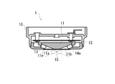
- FIG. 3 is a cross-sectional view taken along line AA in FIG. 2.
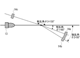
- It is explanatory drawing which showed typically the relationship between a light projection part and a light-receiving part.
- smoke detectors are installed in large buildings such as factory facilities and buildings, underground malls, and rooms such as kitchens and bedrooms in ordinary houses, and are generated in the monitoring area.
- a smoke detector for detecting smoke will be described.
- FIG. 1 is a perspective view of a smoke detector according to the present embodiment.
- 2 is a plan view of FIG. 1
- FIG. 3 is a cross-sectional view taken along line AA of FIG.
- the smoke detector 1 is arranged in a monitoring area to be monitored for smoke generation.
- the smoke sensor 1 projects detection light from the smoke sensor 1 onto the monitoring area, receives detection light scattered by particles present in the monitoring area, and outputs the detection light based on the received detection light. Monitor the output value.
- the smoke detector 1 has a sensor body 10 as a basic structure, and the lower part of the sensor body 10 is formed in a substantially cylindrical shape that is smoothly curved. ing.
- the material of the sensor body 10 is arbitrary, and is made of, for example, resin.
- the sensor body 10 includes a holder 11, a circuit board 12, a light projecting unit 13, and a light receiving unit 14 (specifically, a first light receiving unit 14a, a second light receiving unit 14b, and a third light receiving unit which will be described later). 14c) is provided.
- the holder 11 holds the light projecting unit 13, the light receiving unit 14, and the circuit board 12.
- the light projecting unit 13 and the light receiving unit 14 are held on the lower inner side of the holder 11, and the circuit board 12 is held on the outer upper side of the holder 11.
- the holder 11 is made of an insulating material such as resin, and is disposed on the lower side inside the sensor body 10.
- the connection method of this holder 11 and the sensor main body 10 is arbitrary, for example, the holder 11 and the sensor main body 10 are connected by a fixing member such as a screw.
- the bottom of the holder 11 is formed in a flat shape, and openings 11a to 11d for exposing and holding the light projecting unit 13 and the light receiving unit 14 are provided on the bottom of the holder 11. ing.
- the bottom of the holder 11 has a thin thickness for covering the openings 11a to 11d in order to prevent dust and the like from entering the smoke detector 1 through the openings 11a to 11d.
- a transparent cover 11e is provided.
- the circuit board 12 is for mounting various electric elements. As shown in FIG. 7 to be described later, the circuit board 12 includes a light projecting unit driving circuit 20, a first light receiving unit amplification circuit 21, a second light receiving unit amplification circuit 22, a third light receiving unit amplification circuit 23, and an oscillation unit 30. The control unit 40 and the storage unit 50 are mounted.
- the light projecting unit 13 is a light projecting unit for projecting detection light used for detecting smoke to a monitoring area.
- the specific configuration of the light projecting unit 13, the wavelength of the light projected from the light projecting unit 13, and the like are arbitrary.
- the infrared is a long wavelength light emitting element that emits light having a long wavelength of 870 nm.
- An LED Light Emitting Diode is used.
- the light receiving unit 14 is a light receiving unit that receives detection light scattered by particles present in the monitoring region. Specifically, as shown in FIG. 2, in the present embodiment, a total of three light receiving parts 14 including a first light receiving part 14a, a second light receiving part 14b, and a third light receiving part 14c are provided as the light receiving part 14. It is installed in the holder 11. Specific configurations of the first light receiving unit 14a, the second light receiving unit 14b, and the third light receiving unit 14c are arbitrary. For example, when the light projecting unit 13 is a long wavelength light emitting element such as an infrared LED. In this case, a long wavelength light receiving element having a photodiode for receiving detection light of the long wavelength light emitting element scattered by particles in the monitoring region is used.
- the detection light is projected toward the outside of the smoke detector 1 by the light projecting unit 13 through the opening 11a and the transparent cover 11e.
- the detection light is received by the light receiving unit 14 through the transparent cover 11e and the openings 11b to 11d. That is, a detection space 15 for detecting smoke exists outside the smoke detector 1.
- the smoke detector 1 does not require the detection space 15 to be provided inside the smoke detector 1 as in the prior art. Therefore, the overall height of the smoke detector 1 can be reduced, and the smoke detector 1 is thin. Can be achieved.
- FIG. 4 is an explanatory diagram schematically showing the relationship between the light projecting unit 13 and the light receiving unit 14.
- the angle formed by the light projecting axis of the light projecting unit 13 and the light receiving axis of the first light receiving unit 14a (hereinafter referred to as the first scattering angle ⁇ 1), the light projecting axis of the light projecting unit 13 and the first light receiving axis.
- the angle formed between the light receiving axis of the second light receiving portion 14b hereinafter referred to as the second scattering angle ⁇ 2
- the third light receiving angle hereinafter referred to as the third light receiving angle.
- the first light receiving unit 14a, the second light receiving unit 14b, and the third light receiving unit 14c are arranged so that the scattering angle ⁇ 3 is different.
- FIG. 5 is a diagram illustrating an analysis result of the output value of the light receiving unit 14 corresponding to the scattering angle, where the vertical axis represents the output value of the light receiving unit 14 and the horizontal axis represents the scattering angle.
- the output values corresponding to various types of smoke in FIG. 5, wood burning, wood burning, and dust (here fly ash)
- wood burning, wood burning, and dust here fly ash
- the scattering angle is in the range of 0 ° to 30 °, the light receiving unit 14 is likely to receive direct light from the light projecting unit 13, so that it is difficult to configure the smoke detector 1, and the scattering angle is 60 ° to 140 °.
- the optimum scattering angle range for determining the type of smoke is considered to be a scattering angle range of 30 ° to 60 ° and a scattering angle range of 140 ° to 160 °.
- the number of light receiving units 14 is increased within a scattering angle range of 30 ° to 60 ° where the output values of various smokes vary greatly. By arranging, it is considered that the type of smoke can be easily identified.
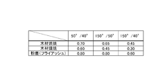
- FIG. 6 is a diagram showing the ratio between the output values of the light receiving unit 14 obtained from the confirmation experiment.
- FIG. 6 shows the ratio between the output value at a scattering angle of 50 ° and the output value at a scattering angle of 40 ° corresponding to various types of smoke (hereinafter referred to as an output ratio of 50 ° / 40 °), the output value at a scattering angle of 150 ° and the scattering angle.
- Ratio with 50 ° output value (hereinafter, output ratio 150 ° / 50 °) and ratio between output value with scattering angle 150 ° and output value with scattering angle 40 ° (hereinafter, output ratio 150 ° / 40 °) It is shown.
- the output ratio 150 ° / 50 ° 0.80
- the output ratio 150 ° / 40 ° 0.60.
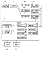
- FIG. 7 is a block diagram conceptually showing the electrical configuration of the smoke detector 1.
- the smoke detector 1 includes a light projecting unit driving circuit 20, a first light receiving unit amplification circuit 21, a second light receiving unit amplification circuit 22, a third light receiving unit amplification circuit 23, an oscillation unit 30, a control unit 40, and a storage unit 50. Configured.
- the light projecting unit drive circuit 20 is a light projecting unit driving means for supplying power to the light projecting unit 13 in order to project the light projecting unit 13.
- the first light receiving unit amplification circuit 21 amplifies the output value output from the first light receiving unit 14a when the detection light of the light projecting unit 13 scattered in the monitoring region is received by the first light receiving unit 14a.
- the first light receiving unit amplifying means for outputting to the control unit 40.
- the second light receiving unit amplification circuit 22 amplifies the output value output from the second light receiving unit 14b when the detection light of the light projecting unit 13 scattered in the monitoring region is received by the second light receiving unit 14b.
- the second light receiving unit amplifying means for outputting to the control unit 40.
- the third light receiving unit amplifier circuit 23 amplifies the output value output from the third light receiving unit 14c when the detection light of the light projecting unit 13 scattered in the monitoring region is received by the third light receiving unit 14c.
- the third light receiving unit amplifying means for outputting to the control unit 40.
- the oscillating unit 30 is an oscillating unit that outputs a reference signal for causing the light projecting unit 13 to project detection light at a predetermined timing.
- the control unit 40 is a control unit that performs various controls in the smoke detector 1.
- the specific configuration of the control unit 40 is arbitrary.
- the control unit 40 can be configured as a CPU (Central Processing Unit) that calls and analyzes a program stored in the storage unit 50.
- the control unit 40 includes a light projection timing switching unit 41, a light projection current variable unit 42, a correction unit 43, a calculation unit 44, a threshold setting unit 45, a gain adjustment unit 46, a smoke type determination unit 47, A fire determination unit 48 and an obstacle determination unit 49 are provided.
- the light projection timing switching unit 41 is a light projection timing switching unit for stepwise switching the light projection timing of the light projection unit 13 based on the reference signal output from the oscillation unit 30.
- the light projecting current varying unit 42 is a light projecting current varying unit for adjusting the luminance of the light projecting unit 13.
- the correcting unit 43 is correcting means for correcting the output values output by the first light receiving unit 14a, the second light receiving unit 14b, and the third light receiving unit 14c.
- the calculation unit 44 is a calculation unit that performs a predetermined calculation using the output values output by the first light receiving unit 14a, the second light receiving unit 14b, and the third light receiving unit 14c.
- the threshold setting unit 45 is a threshold setting unit for setting a threshold for determining whether or not a fire has occurred by the fire determination unit 48.
- the gain adjusting unit 46 is configured to improve the output sensitivity of the first light receiving unit 14a, the second light receiving unit 14b, and the third light receiving unit 14c, the first light receiving unit amplification circuit 21, the second light receiving unit amplification circuit 22, And a gain adjusting means for adjusting the gain of the third light receiving unit amplifying circuit 23.
- the smoke type determining unit 47 determines the type of smoke generated in the monitoring area based on the output values output from the first light receiving unit 14a, the second light receiving unit 14b, and the third light receiving unit 14c. It is.
- the fire determination unit 48 determines whether or not a fire has occurred in the monitoring area based on the output values output from the first light receiving unit 14a, the second light receiving unit 14b, and the third light receiving unit 14c. It is.
- the obstacle determination unit 49 determines whether there is an obstacle in the monitoring area based on output values output from the first light receiving unit 14a, the second light receiving unit 14b, and the third light receiving unit 14c. It is an object determination means.
- the storage unit 50 is a storage unit that stores a program necessary for control by the control unit 40 and various data (for example, a threshold value used for determining whether or not a fire has occurred).
- the specific configuration of the storage unit 50 is arbitrary.
- a nonvolatile storage medium such as a flash memory or an EPROM (Erasable Programmable Read Only Memory) can be used.
- processing Processing executed by the smoke detector 1 configured as described above will be described below. This processing is roughly divided into fire detection processing and obstacle processing. In each of the following processes, the power source of the smoke detector 1 is always turned on, and it is possible to always execute each process according to the program stored in the storage unit 50. Except for this, the control unit 40 performs processing.
- the fire detection process is a process for detecting a fire that has occurred in the monitoring area. This process is roughly divided into a smoke type process and a fire occurrence process.
- the smoke type process is a process for determining the type of smoke generated in the monitoring area
- the fire generation process is a process for determining whether or not a fire has occurred in the monitoring area.
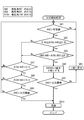
- FIG. 8 is a flowchart of the fire detection process. In the following description, “step” is abbreviated as “S”.
- the smoke type determination unit 47 includes a first light receiving unit 14a, a second light receiving unit 14b, and a third light receiving unit 14c.
- the output value (hereinafter, output value A40 of the first light receiving unit 14a) output from the first light receiving unit 14a having the smallest scattering angle is monitored (SA1).
- SA1 the output value
- the first light receiving unit 14 a is projected onto the monitoring region by the light projecting unit 13 that is supplied with power from the light projecting unit driving circuit 20.
- Detection light scattered by particles in the monitoring region is received, and an output value A40 is output via the first light receiving unit amplifier circuit 21.
- the output value A40 of the first light receiving unit 14a is output from the first light receiving unit 14a via the first light receiving unit amplification circuit 21, and similarly, the output value output from the second light receiving unit 14b.
- the output value A50 of the second light receiving unit 14b is output from the second light receiving unit 14b via the second light receiving unit amplifier circuit 22, and is output from the third light receiving unit 14c (hereinafter referred to as the third light receiving unit).
- the output value A150 of the unit 14c is output from the third light receiving unit 14c via the third light receiving unit amplifier circuit 23. Note that the timing of projecting the detection light projected by the light projecting unit 13 can be arbitrarily changed by the projecting timing switching unit 41 being switched based on the reference signal output from the oscillation unit 30.
- the reason why the smoke is monitored based on the first light receiving portion 14a having the smallest scattering angle in the processing of SA1 is as follows. As shown in FIG. This is because the output value output from the light receiving unit 14 increases. In other words, it can be said that the light detection unit 14 having a smaller scattering angle has higher smoke detection accuracy.
- the SA1 processing is performed based on the first light receiving unit 14a having the first scattering angle [theta] 1.
- the light receiving unit 14 used in the SA1 process is not limited to the first light receiving unit 14a having the smallest scattering angle.
- the smoke type determination unit 47 compares the output values of the first light receiving unit 14a, the second light receiving unit 14b, and the third light receiving unit 14c as necessary, and identifies the light receiving unit 14 having the largest output value.
- smoke that is suspected of causing a fire in the monitoring area It may be determined whether or not the occurrence has occurred.
- the smoke detector 1 can discriminate
- the first light receiving unit 14a is also used in the processes of SA5, SA9, SB5, and SB9 described later.
- the smoke type determination unit 47 determines that smoke generated in the monitoring area is based on the output values output from the first light receiving unit 14a, the second light receiving unit 14b, and the third light receiving unit 14c. The process of determining whether or not smoke is generated during a wood fire). In the present embodiment, two-stage determination is performed. In the first determination, the output ratio between the output value A150 of the third light receiving unit 14c and the output value A40 of the first light receiving unit 14a (hereinafter, output ratio A150 / A40).
- the output ratio between the output value A50 of the second light receiving unit 14b and the output value A40 of the first light receiving unit 14a (hereinafter, output ratio A50 / A40) and the third light receiving unit 14c.
- the output value A150 and the output value 50 of the second light receiving unit 14b are based on the difference in output ratio (hereinafter, output ratio A150 / A50).
- the smoke type determination unit 47 determines that the output ratio A150 / A40 calculated by the calculation unit 44 is 0.40 ⁇ A150. It is determined whether or not /A40 ⁇ 0.55 is satisfied (SA2).
- SA2 the process proceeds to the next determination.
- the calculation unit 44 calculates the output ratio A50 / A40 and the output ratio A150 / A50, and further calculates the absolute value of the difference between the output ratio A50 / A40 and the output ratio A150 / A50. Thereafter, the smoke type determination unit 47 determines whether or not the absolute value of the difference between the output ratio A50 / A40 and the output ratio A150 / A50 satisfies
- the fire determination unit 48 outputs the output value of the first light receiving unit 14a. A14 is monitored.
- the fire determination unit 48 uses the first light receiving unit amplified by the correction unit 43. It is determined whether the output value A40 of 14a exceeds the threshold set by the threshold setting unit 45 (SA5).
- the reason why the output value A40 of the first light receiving unit 14a is corrected is that the amount of smoke generated at the time of the fire is smaller than the amount of smoke generated at the time of the fire. Since the output value A40 of the light receiving unit 14a is small, the first threshold value at the time of the occurrence of the flame fire is determined when the threshold value for determining the SA5 flame fire is the same as the threshold value for determining the SA9 smoke fire described later. This is because the output value A40 of the light receiving unit 14a may not exceed the threshold value.
- the fire determination unit 48 outputs an alarm signal toward a receiver (not shown) arranged in the monitoring area or other area (SA10).
- the control unit 40 when outputting a warning signal toward a receiver or the like (not shown), the control unit 40 may output a signal specifying the type of smoke together with the warning signal. .
- the control unit 40 may perform control so as to change the type of the alarm sound according to the type of smoke.
- the smoke type determination unit 47 performs a process of determining whether or not the smoke generated in the monitoring area is smoke generated during a smoke fire (for example, during a wood fire). In the present embodiment, two-stage determination is performed. In the first determination, smoke generated at the time of smoke fire is determined based on the output ratio A150 / A40, and in the next determination, the output ratio A150 / A50 is determined. Based on this, the smoke generated at the time of smoke fire is judged.
- the smoke type determination unit 47 determines whether or not the output ratio A150 / A40 satisfies A150 / A40 ⁇ 0.40 (SA7).
- SA7 determination value
- SA7 Yes
- the process proceeds to the next determination.
- the smoke type determination unit 47 determines whether or not the output ratio A150 / A50 satisfies A150 / A50 ⁇ 0.80 (SA8).
- the smoke type determination unit 47 returns immediately before SA1.
- the fire determination unit 48 monitors the output value A40 of the first light receiving unit 14a. In the present embodiment, the fire determination unit 48 determines whether or not the output value A40 of the first light receiving unit 14a exceeds the threshold set by the threshold setting unit 45 (SA9).
- the fire determination unit 48 returns to just before SA1.
- the output value A40 of the first light receiving unit 14a exceeds the threshold set by the threshold setting unit 45 (SA9, Yes)
- the fire determination unit 48 outputs an alarm signal toward a receiver or the like (not shown) arranged in the monitoring area or other area (SA10). This completes the fire detection process.
- the reason why the output value A40 of the first light receiving unit 14a amplified by the correction unit 43 is not used as in the process of SA5 is that the smoke amount of smoke generated at the time of smoke fire is Since the output value A40 of the first light receiving unit 14a is large because the amount of smoke generated is large, the threshold value for determining the SA9 smoke fire is the same as the threshold value for determining the SA5 flame fire. This is because even if the threshold value is not corrected, the output value A40 of the first light receiving unit 14a at the time of occurrence of smoke fire exceeds the threshold value.
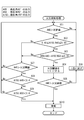
- FIG. 9 is a flowchart of obstacle processing.
- the obstacle determination unit 49 outputs the output value A40 of the first light receiving unit 14a, the output value A50 of the second light receiving unit 14b, and the third value.
- the output value A150 of the light receiving unit 14c is monitored.
- the output value output from the first light receiving unit 14a, the second light receiving unit 14b, or the third light receiving unit 14c is enhanced by noise or the like, so that it may be mistaken for the presence of an obstacle. Therefore, in order to prevent an obstacle detection error, the process of determining whether or not an obstacle exists is repeated.
- the obstacle determination unit 49 Determines whether the total value calculated by the calculation unit 44 satisfies A40 + A50 + A150> 600 (SB2).
- SB2 the reason why the determination value of SB2 is 600 is that the total value of the output value A40 of the first light receiving unit 14a, the output value A50 of the second light receiving unit 14b, and the output value A150 of the third light receiving unit 14c is the maximum output.
- the total value of the maximum outputs of the three light receiving units 14 is 765 bits. This is to determine whether or not an obstacle exists with a value close to (here, 600 bits).
- the obstacle determination unit 49 updates the repeat count m by incrementing the repeat count m by one (SB3).
- the obstacle determination unit 49 monitors the number of repetitions m updated in SB3 (SB4), and repeats the processes of SB2 and SB3 until the number of repetitions m exceeds 10.
- the output value of the first light receiving unit 14a when the total value of the output value A40 of the first light receiving unit 14a, the output value A50 of the second light receiving unit 14b, and the output value A150 of the third light receiving unit 14c does not satisfy A40 + A50 + A150> 600 (SB2, No Furthermore, the output value of the first light receiving unit 14a having the smallest angle between the light receiving axis of the first light receiving unit 14a, the second light receiving unit 14b, or the third light receiving unit 14b and the light projecting axis of the light projecting unit 13 is obtained. Based on this, the obstacle determination unit 49 monitors the output value A40 of the first light receiving unit 14a in order to determine whether there is an obstacle in the monitoring region.
- the obstacle determination unit 49 determines that the output value A40 of the first light receiving unit 14a is within a predetermined time (here, within 5 seconds) after the first detection unit 14a receives the detection light.
- A40> 133 is determined (SB5).
- the reason why the process SB5 is performed using the output value A40 of the first light receiving unit 14a within a predetermined time is that the obstacle is more likely to scatter the detection light than the smoke. This is because the output value for the obstacle and the output value for the smoke are distinguished from each other by utilizing the fact that the increase rate per hour of the value is higher than the increase rate per hour of the output value for the smoke.
- the object determination unit 49 lowers the brightness of the light projecting unit 13 from the normal state, and performs the process of determining whether there is an obstacle in the monitoring area.
- the light projecting current variable unit 42 halves the brightness of the light projecting unit 13 in the normal state
- the gain adjusting unit 46 doubles the gains of the first light receiving unit 14a, the second light receiving unit 14b, and the third light receiving unit 14c in the normal state (SB7).
- the target of the gain shown here is only the change when the predetermined state of the obstacle is used as a reference. Thereafter, the obstacle determination unit 49 returns to immediately before SB1.
- the reason why the luminance of the light projecting unit 13 is 1 ⁇ 2 times the normal state is that, when the luminance of the light projecting unit 13 is in the normal state, the first light receiving unit 14a for the obstacle from SB2 and SB5.
- Output value A40, the output value A50 of the second light receiving unit 14b, and the output value A150 of the third light receiving unit 14c may be saturated, so that these output values A40, A50, A150 are reduced to a level that is not saturated. It is.
- the light projecting current varying unit 42 performs the light projecting unit 13 in the first processing of SB6. Is changed (SB6, Yes), the correction unit 43 outputs the output value A40 of the first light receiving unit 14a, the output value A50 of the second light receiving unit 14b, and the output value A150 of the third light receiving unit 14c.
- the bit value is multiplied by 1/4 (SB8).
- the correction unit 43 sets the bit value of the output value A40 of the first light receiving unit 14a, the output value A50 of the second light receiving unit 14b, and the output value A150 of the third light receiving unit 14c to 1/4 times, This is to reduce noise in the output value A40 of the first light receiving unit 14a, the output value A50 of the second light receiving unit 14b, and the output value A150 of the third light receiving unit 14c due to an obstacle.
- the fire determination unit 48 determines the uncorrected output value A40 of the first light receiving unit 14a based on the threshold set by the threshold setting unit 45 (SB9). ), Return to immediately before SB1.
- the smoke type determination unit 47 has the first light receiving unit 14a, the second light receiving unit 14b, and the third light receiving unit arranged at different positions with respect to the single light projecting unit 13. Since the type of smoke is determined based on the output value output from 14c and the output value output with respect to the detection light scattered in the monitoring region, the first light receiving unit 14a, the second light receiving unit 14b, and When the detection light of the light projecting unit 13 is received at the same timing by the third light receiving unit 14c, the first light receiving unit 14a, the second light receiving unit 14b, and the third light receiving unit with respect to exactly the same smoke generated in the monitoring region.
- the type of smoke can be determined based on the output value output from the unit 14c, and the type of smoke can be accurately determined.
- the smoke type determination unit 47 determines the type of smoke based on the ratio between the output values output from the first light receiving unit 14a, the second light receiving unit 14b, and the third light receiving unit 14c. Without being limited by the magnitude of the output value output from the first light receiving unit 14a, the second light receiving unit 14b, and the third light receiving unit 14c, it is possible to determine the smoke at the time of the fire or the smoke at the time of the fire, It is possible to more accurately determine the type of smoke.
- the smoke type determination unit 47 has the smallest angle formed by the light receiving axis of the first light receiving unit 14a, the second light receiving unit 14b, or the third light receiving unit 14b and the light projecting axis of the light projecting unit 13. Since it is determined whether or not to determine the type of smoke based on the output value A40 of 14a, even if the detection light is difficult to scatter, the first light receiving unit 14a capable of accurately detecting smoke is used. Thus, it is possible to determine whether or not to determine the type of smoke, and to determine the type of smoke accurately and quickly.
- the fire determination unit 48 has the smallest angle formed between the light receiving axis of the first light receiving unit 14a, the second light receiving unit 14b, or the third light receiving unit 14b and the light projecting axis of the light projecting unit 13. Since it is determined whether or not a fire has occurred based on the output value A40, even if the detection light is difficult to scatter, a fire occurs using the first light receiving portion 14a that can detect smoke with high accuracy. It is possible to determine whether or not a fire has occurred and to detect a fire accurately and quickly.
- the fire determination unit 48 determines that the smoke at the time of the flame fire is determined by the smoke type determination unit 47, the output value A40 of the first light receiving unit 14a is corrected. Accordingly, the output value A40 of the first light receiving unit 14a can be corrected, and a fire can be detected more accurately.
- the obstacle determination unit 49 is an output value output from the first light receiving unit 14a, the second light receiving unit 14b, and the third light receiving unit 14c arranged at different positions with respect to one light projecting unit 13. Therefore, it is determined whether there is an obstacle based on the output value output for the detection light scattered in the monitoring region, so the first light receiving unit 14a, the second light receiving unit 14b, and the third light receiving unit By receiving the detection light of the light projecting unit 13 at the same timing by 14c, output values output from the first light receiving unit 14a, the second light receiving unit 14b, and the third light receiving unit 14c with respect to the completely same obstacle Based on the above, it can be determined whether or not an obstacle exists, and the obstacle can be accurately detected.
- the obstacle determination unit 49 determines whether there is an obstacle in the monitoring area based on the total value of the output values output from the first light receiving unit 14a, the second light receiving unit 14b, and the third light receiving unit 14c. Therefore, by integrating the output values output from the first light receiving unit 14a, the second light receiving unit 14b, and the third light receiving unit 14c, it can be determined whether there is an obstacle, Obstacles can be detected more accurately.
- the obstacle determination unit 49 has the smallest angle formed by the light receiving axis of the first light receiving unit 14a, the second light receiving unit 14b, or the third light receiving unit 14b and the light projecting axis of the light projecting unit 13. Since it is determined based on the output value A40 of 14a whether or not there is an obstacle, the first light receiving unit 14a capable of accurately detecting the obstacle is used even if the detection light is difficult to scatter. Thus, it can be determined whether or not an obstacle exists, and the obstacle can be detected accurately and quickly.
- each of the electrical components described above is functionally conceptual and does not necessarily need to be physically configured as illustrated.
- the specific form of distribution / integration of each part is not limited to the one shown in the figure, and all or a part thereof may be functionally or physically distributed / integrated in arbitrary units according to various loads and usage conditions.
- an analog output value may be output from the smoke detector 1 to the receiver, and the smoke type determination or fire occurrence determination may be performed on the receiver side.
- all or part of the control unit 40 and the storage unit 50 of the smoke detector 1 described in the present embodiment may be provided in the receiver.
- the light projection timing switching unit 41 can arbitrarily switch the light projection timing of the detection light projected by the light projecting unit 13, but for example, the light projection timing switching unit 41 is a process.
- the timing of light projection may be switched according to the contents of For example, in the fire detection process, until the output value A40 of the first light receiving unit 14a falls below a predetermined value (SA1, No), the light projecting unit 13 projects detection light once every 5 seconds, and the first light receiving unit 14a After the output value A40 exceeds the predetermined value (SA1, Yes), the light projection timing switching unit 41 switches the light projection timing so that the light projecting unit 13 projects the detection light once every 2 seconds. Also good.
- the processing from SA2 to SA5 is processing for discriminating a flame and determining the occurrence of the fire. Details of these processing are omitted, but in the processing of SA4, the correction unit 43 Has explained that the output value A40 of the first light receiving unit 14a is tripled, but based on the smoke type determined by the smoke type determining unit 47, a determination criterion for determining whether or not a fire has occurred in the monitoring area May be changed.
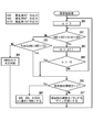
- FIG. 10 is a flowchart of the fire detection process according to the modification.
- the processing from SC2 to SC5 shown in FIG. 10 is the same as the processing from SA2 to SA5 in FIG.
- the threshold setting unit 45 may set the threshold for determining the output value A40 of the first light receiving unit 14a to 1/3 times.
- the threshold setting unit 45 may set the threshold used in the SC5 process and the threshold used in the SC7 process separately from each other, and may omit the SC4 process.
- each process in the process shown in FIGS. 8 to 10 can be arbitrarily changed unless otherwise specified.
- the fire occurrence is determined in SA9.
- the fire is generated in the process of SC7 as in the process of FIG. After performing the determination, the smoke fire may be determined by the processing of SC8 and SC9.
- SYMBOLS 1 Smoke detector 10 Sensor main body 11 Holder 11a, 11b, 11c, 11d Opening part 11e Transparent cover 12 Circuit board 13 Light projection part 14 Light reception part 14a 1st light reception part 14b 2nd light reception part 14c 3rd light reception part 15 Detection space DESCRIPTION OF SYMBOLS 20 Light projection part drive circuit 21 1st light-receiving part amplification circuit 22 2nd light-receiving part amplification circuit 23 3rd light-receiving part amplification circuit 30 Oscillation part 40 Control part 41 Light projection timing switching part 42 Light projection current variable part 43 Correction
Landscapes
- Analytical Chemistry (AREA)
- General Physics & Mathematics (AREA)
- Physics & Mathematics (AREA)
- Chemical & Material Sciences (AREA)
- General Health & Medical Sciences (AREA)
- Biochemistry (AREA)
- Life Sciences & Earth Sciences (AREA)
- Health & Medical Sciences (AREA)
- Immunology (AREA)
- Pathology (AREA)
- Business, Economics & Management (AREA)
- Emergency Management (AREA)
- Fire-Detection Mechanisms (AREA)
- Investigating Or Analysing Materials By Optical Means (AREA)
Abstract
Description
まず、煙感知器の構成を説明する。図1は、本実施の形態に係る煙感知器の斜視図である。図2は、図1の平面図、図3は、図2のA-A矢視断面図である。
次に、煙感知器1の電気的構成について説明する。図7は、煙感知器1の電気的構成を概念的に示すブロック図である。煙感知器1は、投光部駆動回路20、第1受光部増幅回路21、第2受光部増幅回路22、第3受光部増幅回路23、発振部30、制御部40、記憶部50を備えて構成されている。
このように構成される煙感知器1によって実行される処理について以下説明する。この処理は、火災検知処理及び障害物処理に大別される。以下の各処理では、煙感知器1の電源は常時ONされており、記憶部50にて記憶されたプログラムに従って、各処理を常に実行することが可能となっているものとし、特記する主体を除いて制御部40にて処理が行われる。
最初に、火災検知処理について説明する。火災検知処理は、監視領域で発生した火災を検知する処理である。この処理は、煙種別処理及び火災発生処理に大別される。煙種別処理は、監視領域で発生した煙の種別を判定する処理であり、火災発生処理は、監視領域で火災が発生したか否かを判定する処理である。この火災検知処理では、煙種別処理が行われた後に(主に煙種別判定部47によって処理される)、火災発生処理が行われる(主に火災判定部48によって処理される)。図8は火災検知処理のフローチャートである。なお、以下の説明では、「ステップ」を「S」と略記する。
次に、障害物処理について説明する。この処理は、監視領域に障害物が存在するか否かを判定するための処理である。図9は障害物処理のフローチャートである。
このように本実施の形態によれば、煙種別判定部47が、一つの投光部13に対して異なる位置に配置された第1受光部14a、第2受光部14b、及び第3受光部14cから出力された出力値であって、監視領域で散乱した検出光に対して出力された出力値に基づいて煙の種別を判定するので、第1受光部14a、第2受光部14b、及び第3受光部14cによって同じタイミングで投光部13の検出光が受光されることにより、監視領域で発生した全く同じ煙に対して第1受光部14a、第2受光部14b、及び第3受光部14cから出力された出力値に基づいて煙の種別を判定することでき、正確に煙の種類を判別することができる。
以上、本発明に係る実施の形態について説明したが、本発明の具体的な構成及び手段は、特許請求の範囲に記載した各発明の技術的思想の範囲内において、任意に改変及び改良することができる。以下、このような変形例について説明する。
まず、発明が解決しようとする課題や発明の効果は、前記した内容に限定されるものではなく、本発明によって、前記に記載されていない課題を解決したり、前記に記載されていない効果を奏することもでき、また、記載されている課題の一部のみを解決したり、記載されている効果の一部のみを奏することがある。
また、上述した各電気的構成要素は機能概念的なものであり、必ずしも物理的に図示の如く構成されていることを要しない。すなわち、各部の分散・統合の具体的形態は図示のものに限られず、その全部または一部を、各種の負荷や使用状況などに応じて、任意の単位で機能的または物理的に分散・統合して構成できる。例えば、煙感知器1から受信機にアナログ出力値を出力し、受信機側で煙の種別判定や火災発生の判定を行ってもよい。この場合には、本実施の形態で説明した煙感知器1の制御部40や記憶部50の全部又は一部を、受信機に備えて構成してもよい。
本実施の形態では、投光タイミング切替部41は、投光部13によって投光される検出光の投光のタイミングを任意に切り替えることができるが、例えば、投光タイミング切替部41は、処理の内容に応じて投光のタイミングを切り替えてもよい。例えば、火災検知処理において、第1受光部14aの出力値A40が所定値を下回るまでは(SA1、No)、投光部13が5secにつき1回検出光を投光し、第1受光部14aの出力値A40が所定値を上回った後は(SA1、Yes)、投光部13が2secにつき1回検出光を投光するように、投光タイミング切替部41は投光のタイミングを切り替えてもよい。
本実施の形態では、SA2からSA5の処理は、発炎火災の判別とその火災発生の判定を行う処理であり、これら処理の詳細は省略するが、このうちのSA4の処理において、補正部43が第1受光部14aの出力値A40を3倍にすると説明したが、煙種別判定部47よって判定された煙の種別に基づいて、監視領域で火災が発生したか否かを判定する判定基準を変更してもよい。
10 感知器本体
11 ホルダ
11a、11b、11c、11d 開口部
11e 透明カバー
12 回路基板
13 投光部
14 受光部
14a 第1受光部
14b 第2受光部
14c 第3受光部
15 検知空間
20 投光部駆動回路
21 第1受光部増幅回路
22 第2受光部増幅回路
23 第3受光部増幅回路
30 発振部
40 制御部
41 投光タイミング切替部
42 投光電流可変部
43 補正部
44 演算部
45 閾値設定部
46 ゲイン調整部
47 煙種別判定部
48 火災判定部
49 障害物判定部
50 記憶部
Claims (14)
- 監視領域に対して検出光を投光する投光手段と、
前記監視領域に存在する粒子によって、散乱された前記検出光を受光する複数の受光手段であって、当該受光手段の受光軸と前記投光手段の投光軸とのなす角度が各々異なるように配置された複数の受光手段と、
前記複数の受光手段から出力された出力値に基づいて、前記監視領域で発生した煙の種別を判定する煙種別判定手段と、
前記複数の受光手段から出力された出力値に基づいて、前記監視領域で火災が発生したか否かを判定する火災判定手段と、
を備えた煙感知システム。 - 前記煙種別判定手段は、前記複数の受光手段から出力された出力値の相互間の比に基づいて、前記監視領域で発生した煙の種別を判定する、
請求項1に記載の煙感知システム。 - 前記煙種別判定手段は、前記複数の受光手段のうち、出力値が最も大きい受光手段の出力値に基づいて、前記監視領域で発生した煙の種別の判定を行うか否かを判定する、
請求項1又は2に記載の煙感知システム。 - 前記火災判定手段は、前記複数の受光手段のうち、出力値が最も大きい受光手段の出力値に基づいて、前記監視領域で火災が発生したか否かを判定する、
請求項1から3のいずれか一項に記載の煙感知システム。 - 前記煙種別判定手段は、前記複数の受光手段のうち、当該受光手段の受光軸と前記投光手段の投光軸とのなす角度が最も小さい受光手段の出力値に基づいて、前記監視領域で発生した煙の種別の判定を行うか否かを判定する、
請求項1又は2に記載の煙感知システム。 - 前記火災判定手段は、前記複数の受光手段のうち、当該受光手段の受光軸と前記投光手段の投光軸とのなす角度が最も小さい受光手段の出力値に基づいて、前記監視領域で火災が発生したか否かを判定する、
請求項1、2、及び5のいずれか一項に記載の煙感知システム。 - 前記火災判定手段は、前記煙種別判定手段によって判定された前記煙の種別に基づいて、前記監視領域で火災が発生したか否かを判定する判定基準を変更する、
請求項1から6のいずれか一項に記載の煙感知システム。 - 前記火災判定手段は、前記煙種別判定手段によって判定された前記煙の種別に基づいて、前記受光手段から出力された出力値を補正する、
請求項1から6のいずれか一項に記載の煙感知システム。 - 前記複数の受光手段から出力された出力値に基づいて、前記監視領域に障害物が存在するか否かを判定する障害物判定手段、
を備えた請求項1から8のいずれか一項に記載の煙感知システム。 - 前記障害物判定手段は、前記複数の受光手段から出力された出力値の合計値に基づいて、前記監視領域に障害物が存在するか否かを判定する、
請求項9に記載の煙感知システム。 - 前記障害物判定手段は、前記複数の受光手段のうち、出力値が最も大きい受光手段の出力値に基づいて、前記監視領域に障害物が存在するか否かを判定する、
請求項9に記載の煙感知システム。 - 前記障害物判定手段は、前記複数の受光手段のうち、当該受光手段の受光軸と前記投光手段の投光軸とのなす角度が最も小さい受光手段の出力値に基づいて、前記監視領域に障害物が存在するか否かを判定する、
請求項9に記載の煙感知システム。 - 監視領域に対して検出光を投光する投光手段と、
前記監視領域に存在する粒子によって、散乱された前記検出光を受光する複数の受光手段であって、当該受光手段の受光軸と前記投光手段の投光軸とのなす角度が各々異なるように配置された複数の受光手段と、
前記複数の受光手段から出力された出力値に基づいて、前記監視領域で発生した煙の種別を判定する煙種別判定手段と、
前記複数の受光手段から出力された出力値に基づいて、前記監視領域で火災が発生したか否かを判定する火災判定手段と、
を備えた煙感知器。 - 監視領域に対して検出光を投光する投光手段と、前記監視領域に存在する粒子によって、散乱された前記検出光を受光する複数の受光手段とを備えた煙感知器から出力された出力値を受信する受信機であって、
前記煙感知器から受信した出力値に基づいて、前記監視領域で発生した煙の種別を判定する煙種別判定手段と、
前記煙感知器から受信した出力値に基づいて、前記監視領域で火災が発生したか否かを判定する火災判定手段と、
を備えた受信機。
Priority Applications (6)
| Application Number | Priority Date | Filing Date | Title |
|---|---|---|---|
| CN200980161482.6A CN102498384B (zh) | 2009-09-15 | 2009-09-15 | 烟雾感测器 |
| AU2009352856A AU2009352856B2 (en) | 2009-09-15 | 2009-09-15 | Smoke sensor |
| PCT/JP2009/004602 WO2011033552A1 (ja) | 2009-09-15 | 2009-09-15 | 煙感知器 |
| EP09849413.1A EP2472250A4 (en) | 2009-09-15 | 2009-09-15 | SMOKE DETECTOR |
| US13/395,626 US8638436B2 (en) | 2009-09-15 | 2009-09-15 | Smoke sensor |
| JP2011531632A JP5432271B2 (ja) | 2009-09-15 | 2009-09-15 | 煙感知器 |
Applications Claiming Priority (1)
| Application Number | Priority Date | Filing Date | Title |
|---|---|---|---|
| PCT/JP2009/004602 WO2011033552A1 (ja) | 2009-09-15 | 2009-09-15 | 煙感知器 |
Publications (1)
| Publication Number | Publication Date |
|---|---|
| WO2011033552A1 true WO2011033552A1 (ja) | 2011-03-24 |
Family
ID=43758182
Family Applications (1)
| Application Number | Title | Priority Date | Filing Date |
|---|---|---|---|
| PCT/JP2009/004602 Ceased WO2011033552A1 (ja) | 2009-09-15 | 2009-09-15 | 煙感知器 |
Country Status (6)
| Country | Link |
|---|---|
| US (1) | US8638436B2 (ja) |
| EP (1) | EP2472250A4 (ja) |
| JP (1) | JP5432271B2 (ja) |
| CN (1) | CN102498384B (ja) |
| AU (1) | AU2009352856B2 (ja) |
| WO (1) | WO2011033552A1 (ja) |
Cited By (2)
| Publication number | Priority date | Publication date | Assignee | Title |
|---|---|---|---|---|
| JP2014067296A (ja) * | 2012-09-26 | 2014-04-17 | Nohmi Bosai Ltd | 煙感知器 |
| WO2023238849A1 (ja) * | 2022-06-09 | 2023-12-14 | 能美防災株式会社 | 煙検知装置 |
Families Citing this family (19)
| Publication number | Priority date | Publication date | Assignee | Title |
|---|---|---|---|---|
| EP2706515B1 (de) | 2012-09-07 | 2014-11-12 | Amrona AG | Vorrichtung und Verfahren zum Detektieren von Streulichtsignalen |
| GB201319988D0 (en) * | 2013-11-13 | 2013-12-25 | Univ Lancaster | Smoke detector |
| EP3225977B1 (en) * | 2016-03-31 | 2019-03-13 | ams AG | Method and sensor system for detecting particles |
| WO2018011232A1 (en) | 2016-07-11 | 2018-01-18 | Autronica Fire & Security As | Smoke detector dynamic range adjustment system and method |
| US10769921B2 (en) | 2016-08-04 | 2020-09-08 | Carrier Corporation | Smoke detector |
| US11062586B2 (en) | 2017-06-05 | 2021-07-13 | Carrier Corporation | Method of monitoring health of protective cover of detection device |
| CN111263958B (zh) * | 2017-10-30 | 2022-05-27 | 开利公司 | 检测器装置中的补偿器 |
| WO2019189125A1 (ja) | 2018-03-28 | 2019-10-03 | ホーチキ株式会社 | 火災検出装置 |
| WO2020014461A2 (en) | 2018-07-13 | 2020-01-16 | Carrier Corporation | Enhanced robustness for high sensitivity fiber optic smoke detection |
| EP3821410A4 (en) | 2018-07-13 | 2022-03-09 | Carrier Corporation | DETECTION BASED ON HIGHLY SENSITIVE FIBER OPTICS |
| US11176796B2 (en) | 2018-07-13 | 2021-11-16 | Carrier Corporation | High sensitivity fiber optic based detection |
| US10697880B1 (en) * | 2019-04-07 | 2020-06-30 | Everday Technology Co., Ltd. | Smoke detecting device |
| US11238716B2 (en) * | 2019-11-27 | 2022-02-01 | Ningbo Weilaiying Electronic Technology Co., Ltd | Photoelectric smoke fire detection and alarming method, apparatus and system |
| US11127284B1 (en) * | 2020-07-02 | 2021-09-21 | Honeywell International Inc. | Self-calibrating fire sensing device |
| US11615684B2 (en) * | 2020-11-24 | 2023-03-28 | Pixart Imaging Inc. | Smoke detector |
| US12039848B2 (en) * | 2021-10-28 | 2024-07-16 | Honeywell International Inc. | Non-coaxial systems, methods, and devices for detecting smoke |
| US12417688B2 (en) | 2022-08-08 | 2025-09-16 | Kidde Fire Protection, Llc | Single-wave multi-angle smoke alarm algorithm |
| US20250003860A1 (en) * | 2023-05-26 | 2025-01-02 | Electronics And Telecommunications Research Institute | Apparatus and method for detecting smoke using multi-angle light scattering |
| WO2026054803A1 (en) * | 2024-09-04 | 2026-03-12 | Microchip Technology Incorporated | Noise suppression using multiple light sensors in a photoelectric smoke detector |
Citations (12)
| Publication number | Priority date | Publication date | Assignee | Title |
|---|---|---|---|---|
| JPS5799290U (ja) * | 1980-12-10 | 1982-06-18 | ||
| JPH0342800A (ja) * | 1989-07-11 | 1991-02-22 | Nohmi Bosai Ltd | 光ワイヤレス式火災報知設備 |
| JPH04124798A (ja) * | 1990-09-14 | 1992-04-24 | Matsushita Electric Works Ltd | 光電式煙感知器 |
| JPH04299499A (ja) * | 1991-03-27 | 1992-10-22 | Hochiki Corp | 火災警報装置 |
| JPH0581578A (ja) * | 1991-09-20 | 1993-04-02 | Hochiki Corp | 火災報知装置 |
| JPH05128381A (ja) * | 1991-10-31 | 1993-05-25 | Hochiki Corp | 火災報知装置 |
| JPH06109631A (ja) * | 1991-10-31 | 1994-04-22 | Hochiki Corp | 火災報知装置 |
| JPH0712724A (ja) * | 1993-04-30 | 1995-01-17 | Hochiki Corp | 火災報知装置及び火災検出方法 |
| JPH1123458A (ja) | 1997-05-08 | 1999-01-29 | Nittan Co Ltd | 煙感知器および監視制御システム |
| JP2004325211A (ja) * | 2003-04-24 | 2004-11-18 | Hochiki Corp | 散乱光式煙感知器 |
| WO2005048208A1 (ja) * | 2003-11-17 | 2005-05-26 | Hochiki Corporation | 散乱光式煙感知器 |
| JP2006526211A (ja) * | 2004-01-13 | 2006-11-16 | ローベルト ボツシユ ゲゼルシヤフト ミツト ベシユレンクテル ハフツング | 火災報知器 |
Family Cites Families (18)
| Publication number | Priority date | Publication date | Assignee | Title |
|---|---|---|---|---|
| JPS5799290A (en) | 1980-12-10 | 1982-06-19 | Hitachi Ltd | Air conditioner |
| US4642471A (en) * | 1982-10-11 | 1987-02-10 | Cerberus Ag | Scattered radiation smoke detector |
| JP3035341B2 (ja) | 1990-11-30 | 2000-04-24 | 能美防災株式会社 | 煙感知器 |
| GB2259763B (en) * | 1991-09-20 | 1995-05-31 | Hochiki Co | Fire alarm system |
| US5502434A (en) * | 1992-05-29 | 1996-03-26 | Hockiki Kabushiki Kaisha | Smoke sensor |
| GB2274333B (en) * | 1993-01-07 | 1996-12-11 | Hochiki Co | Smoke detecting apparatus capable of detecting both smoke and fine particles |
| US5576697A (en) | 1993-04-30 | 1996-11-19 | Hochiki Kabushiki Kaisha | Fire alarm system |
| DE19902319B4 (de) * | 1999-01-21 | 2011-06-30 | Novar GmbH, Albstadt-Ebingen Zweigniederlassung Neuss, 41469 | Streulichtbrandmelder |
| DE10066246A1 (de) * | 2000-09-22 | 2005-10-06 | Robert Bosch Gmbh | Streulichtrauchmelder |
| US6967582B2 (en) * | 2002-09-19 | 2005-11-22 | Honeywell International Inc. | Detector with ambient photon sensor and other sensors |
| JP4205400B2 (ja) | 2002-11-12 | 2009-01-07 | ユニ・チャーム株式会社 | 連続生産する使い捨て着用物品に弾性部材を取り付ける方法およびそのための装置 |
| CN1234003C (zh) * | 2003-01-17 | 2005-12-28 | 海湾安全技术有限公司 | 立式双向散射型光电感烟探测器 |
| CN100463006C (zh) * | 2003-11-17 | 2009-02-18 | 报知机股份有限公司 | 光散射型烟雾传感器 |
| WO2007060765A1 (ja) | 2005-11-28 | 2007-05-31 | Matsushita Electric Industrial Co., Ltd. | タイミング抽出装置、並びにこれを用いた情報再生装置及びdvd装置 |
| WO2007096964A1 (ja) * | 2006-02-23 | 2007-08-30 | Hochiki Corporation | 分離型感知器 |
| EP2034462A4 (en) * | 2006-05-12 | 2011-05-18 | Panasonic Elec Works Co Ltd | SMOKE SENSOR OF SOUND WAVE TYPE |
| KR20100037539A (ko) * | 2008-10-01 | 2010-04-09 | 노미 보사이 가부시키가이샤 | 광전식 연기 감지기 |
| AU2009301879B2 (en) * | 2008-10-09 | 2014-10-09 | Hochiki Corporation | Smoke detector |
-
2009
- 2009-09-15 WO PCT/JP2009/004602 patent/WO2011033552A1/ja not_active Ceased
- 2009-09-15 AU AU2009352856A patent/AU2009352856B2/en not_active Ceased
- 2009-09-15 JP JP2011531632A patent/JP5432271B2/ja not_active Expired - Fee Related
- 2009-09-15 US US13/395,626 patent/US8638436B2/en not_active Expired - Fee Related
- 2009-09-15 CN CN200980161482.6A patent/CN102498384B/zh not_active Expired - Fee Related
- 2009-09-15 EP EP09849413.1A patent/EP2472250A4/en not_active Withdrawn
Patent Citations (12)
| Publication number | Priority date | Publication date | Assignee | Title |
|---|---|---|---|---|
| JPS5799290U (ja) * | 1980-12-10 | 1982-06-18 | ||
| JPH0342800A (ja) * | 1989-07-11 | 1991-02-22 | Nohmi Bosai Ltd | 光ワイヤレス式火災報知設備 |
| JPH04124798A (ja) * | 1990-09-14 | 1992-04-24 | Matsushita Electric Works Ltd | 光電式煙感知器 |
| JPH04299499A (ja) * | 1991-03-27 | 1992-10-22 | Hochiki Corp | 火災警報装置 |
| JPH0581578A (ja) * | 1991-09-20 | 1993-04-02 | Hochiki Corp | 火災報知装置 |
| JPH05128381A (ja) * | 1991-10-31 | 1993-05-25 | Hochiki Corp | 火災報知装置 |
| JPH06109631A (ja) * | 1991-10-31 | 1994-04-22 | Hochiki Corp | 火災報知装置 |
| JPH0712724A (ja) * | 1993-04-30 | 1995-01-17 | Hochiki Corp | 火災報知装置及び火災検出方法 |
| JPH1123458A (ja) | 1997-05-08 | 1999-01-29 | Nittan Co Ltd | 煙感知器および監視制御システム |
| JP2004325211A (ja) * | 2003-04-24 | 2004-11-18 | Hochiki Corp | 散乱光式煙感知器 |
| WO2005048208A1 (ja) * | 2003-11-17 | 2005-05-26 | Hochiki Corporation | 散乱光式煙感知器 |
| JP2006526211A (ja) * | 2004-01-13 | 2006-11-16 | ローベルト ボツシユ ゲゼルシヤフト ミツト ベシユレンクテル ハフツング | 火災報知器 |
Non-Patent Citations (1)
| Title |
|---|
| See also references of EP2472250A4 * |
Cited By (4)
| Publication number | Priority date | Publication date | Assignee | Title |
|---|---|---|---|---|
| JP2014067296A (ja) * | 2012-09-26 | 2014-04-17 | Nohmi Bosai Ltd | 煙感知器 |
| WO2023238849A1 (ja) * | 2022-06-09 | 2023-12-14 | 能美防災株式会社 | 煙検知装置 |
| JPWO2023238849A1 (ja) * | 2022-06-09 | 2023-12-14 | ||
| JP7788552B2 (ja) | 2022-06-09 | 2025-12-18 | 能美防災株式会社 | 煙検知装置 |
Also Published As
| Publication number | Publication date |
|---|---|
| EP2472250A4 (en) | 2015-04-29 |
| CN102498384B (zh) | 2015-09-02 |
| AU2009352856A1 (en) | 2012-03-15 |
| JP5432271B2 (ja) | 2014-03-05 |
| AU2009352856B2 (en) | 2014-07-10 |
| CN102498384A (zh) | 2012-06-13 |
| US20120170035A1 (en) | 2012-07-05 |
| US8638436B2 (en) | 2014-01-28 |
| JPWO2011033552A1 (ja) | 2013-02-07 |
| EP2472250A1 (en) | 2012-07-04 |
Similar Documents
| Publication | Publication Date | Title |
|---|---|---|
| JP5432271B2 (ja) | 煙感知器 | |
| US10234388B2 (en) | System for determining abnormality in a monitored area | |
| US8890700B2 (en) | Evaluating scattered-light signals in an optical hazard detector and outputting a dust/steam warning or a fire alarm | |
| AU2010201566B2 (en) | Light scattering type smoke sensor | |
| US9297753B2 (en) | Photoelectric smoke sensor | |
| JP2016537647A (ja) | 外部サンプリング体積および周囲光拒絶を有する煙検出器 | |
| JP2020035029A (ja) | 光電式煙感知器 | |
| CN101300611B (zh) | 组合的散射光和消光火警探测器 | |
| JP2010044536A (ja) | 煙感知器 | |
| JP2013003760A (ja) | 煙感知器 | |
| JP5901485B2 (ja) | 煙感知器 | |
| JP2019220113A (ja) | 煙感知器及び煙検知システム | |
| JP6009802B2 (ja) | 火災感知器 | |
| JP5377390B2 (ja) | 煙感知器 | |
| KR20150107130A (ko) | 화재 감지기 | |
| US12417688B2 (en) | Single-wave multi-angle smoke alarm algorithm | |
| JP5046552B2 (ja) | 光電式煙感知器 | |
| JP6858612B2 (ja) | 火災警報器 | |
| JP2005250986A (ja) | 火災感知器 | |
| US20250329239A1 (en) | Smoke detecting apparatus, chamber therein, and fire detecting method thereof | |
| JP2011070409A (ja) | 警報器 | |
| KR101179082B1 (ko) | 화재 감지기의 제어방법 | |
| KR101098326B1 (ko) | 화재 감지기 | |
| JP2013069160A (ja) | 火災感知器 | |
| JP6858613B2 (ja) | 火災警報器 |
Legal Events
| Date | Code | Title | Description |
|---|---|---|---|
| WWE | Wipo information: entry into national phase |
Ref document number: 200980161482.6 Country of ref document: CN |
|
| 121 | Ep: the epo has been informed by wipo that ep was designated in this application |
Ref document number: 09849413 Country of ref document: EP Kind code of ref document: A1 |
|
| WWE | Wipo information: entry into national phase |
Ref document number: 2009352856 Country of ref document: AU |
|
| WWE | Wipo information: entry into national phase |
Ref document number: 2011531632 Country of ref document: JP |
|
| WWE | Wipo information: entry into national phase |
Ref document number: 13395626 Country of ref document: US |
|
| ENP | Entry into the national phase |
Ref document number: 2009352856 Country of ref document: AU Date of ref document: 20090915 Kind code of ref document: A |
|
| NENP | Non-entry into the national phase |
Ref country code: DE |
|
| WWE | Wipo information: entry into national phase |
Ref document number: 2009849413 Country of ref document: EP |