WO2011033624A1 - 全熱交換素子 - Google Patents
全熱交換素子 Download PDFInfo
- Publication number
- WO2011033624A1 WO2011033624A1 PCT/JP2009/066163 JP2009066163W WO2011033624A1 WO 2011033624 A1 WO2011033624 A1 WO 2011033624A1 JP 2009066163 W JP2009066163 W JP 2009066163W WO 2011033624 A1 WO2011033624 A1 WO 2011033624A1
- Authority
- WO
- WIPO (PCT)
- Prior art keywords
- adhesive
- partition
- heat exchange
- partition member
- members
- Prior art date
- Legal status (The legal status is an assumption and is not a legal conclusion. Google has not performed a legal analysis and makes no representation as to the accuracy of the status listed.)
- Ceased
Links
Images




Classifications
-
- F—MECHANICAL ENGINEERING; LIGHTING; HEATING; WEAPONS; BLASTING
- F28—HEAT EXCHANGE IN GENERAL
- F28D—HEAT-EXCHANGE APPARATUS, NOT PROVIDED FOR IN ANOTHER SUBCLASS, IN WHICH THE HEAT-EXCHANGE MEDIA DO NOT COME INTO DIRECT CONTACT
- F28D21/00—Heat-exchange apparatus not covered by any of the groups F28D1/00 - F28D20/00
- F28D21/0015—Heat and mass exchangers, e.g. with permeable walls
-
- F—MECHANICAL ENGINEERING; LIGHTING; HEATING; WEAPONS; BLASTING
- F28—HEAT EXCHANGE IN GENERAL
- F28F—DETAILS OF HEAT-EXCHANGE AND HEAT-TRANSFER APPARATUS, OF GENERAL APPLICATION
- F28F3/00—Plate-like or laminated elements; Assemblies of plate-like or laminated elements
- F28F3/02—Elements or assemblies thereof with means for increasing heat-transfer area, e.g. with fins, with recesses, with corrugations
- F28F3/06—Elements or assemblies thereof with means for increasing heat-transfer area, e.g. with fins, with recesses, with corrugations the means being attachable to the element
-
- F—MECHANICAL ENGINEERING; LIGHTING; HEATING; WEAPONS; BLASTING
- F28—HEAT EXCHANGE IN GENERAL
- F28D—HEAT-EXCHANGE APPARATUS, NOT PROVIDED FOR IN ANOTHER SUBCLASS, IN WHICH THE HEAT-EXCHANGE MEDIA DO NOT COME INTO DIRECT CONTACT
- F28D9/00—Heat-exchange apparatus having stationary plate-like or laminated conduit assemblies for both heat-exchange media, the media being in contact with different sides of a conduit wall
- F28D9/0062—Heat-exchange apparatus having stationary plate-like or laminated conduit assemblies for both heat-exchange media, the media being in contact with different sides of a conduit wall the conduits for one heat-exchange medium being formed by spaced plates with inserted elements
-
- F—MECHANICAL ENGINEERING; LIGHTING; HEATING; WEAPONS; BLASTING
- F28—HEAT EXCHANGE IN GENERAL
- F28F—DETAILS OF HEAT-EXCHANGE AND HEAT-TRANSFER APPARATUS, OF GENERAL APPLICATION
- F28F3/00—Plate-like or laminated elements; Assemblies of plate-like or laminated elements
- F28F3/08—Elements constructed for building-up into stacks, e.g. capable of being taken apart for cleaning
-
- F—MECHANICAL ENGINEERING; LIGHTING; HEATING; WEAPONS; BLASTING
- F24—HEATING; RANGES; VENTILATING
- F24F—AIR-CONDITIONING; AIR-HUMIDIFICATION; VENTILATION; USE OF AIR CURRENTS FOR SCREENING
- F24F3/00—Air-conditioning systems in which conditioned primary air is supplied from one or more central stations to distributing units in the rooms or spaces where it may receive secondary treatment; Apparatus specially designed for such systems
- F24F3/12—Air-conditioning systems in which conditioned primary air is supplied from one or more central stations to distributing units in the rooms or spaces where it may receive secondary treatment; Apparatus specially designed for such systems characterised by the treatment of the air otherwise than by heating and cooling
- F24F3/14—Air-conditioning systems in which conditioned primary air is supplied from one or more central stations to distributing units in the rooms or spaces where it may receive secondary treatment; Apparatus specially designed for such systems characterised by the treatment of the air otherwise than by heating and cooling by humidification; by dehumidification
- F24F2003/1435—Air-conditioning systems in which conditioned primary air is supplied from one or more central stations to distributing units in the rooms or spaces where it may receive secondary treatment; Apparatus specially designed for such systems characterised by the treatment of the air otherwise than by heating and cooling by humidification; by dehumidification comprising semi-permeable membrane
-
- F—MECHANICAL ENGINEERING; LIGHTING; HEATING; WEAPONS; BLASTING
- F28—HEAT EXCHANGE IN GENERAL
- F28F—DETAILS OF HEAT-EXCHANGE AND HEAT-TRANSFER APPARATUS, OF GENERAL APPLICATION
- F28F2275/00—Fastening; Joining
- F28F2275/02—Fastening; Joining by using bonding materials; by embedding elements in particular materials
- F28F2275/025—Fastening; Joining by using bonding materials; by embedding elements in particular materials by using adhesives
Definitions
- the present invention relates to a plate stack type total heat exchange element that performs total heat exchange between two fluids in different states, and is particularly incorporated in a ventilator or an air conditioner to perform total heat exchange between air and air.
- the present invention relates to a total heat exchanging element suitable for a thing.
- the plate-stacked heat exchange element is widely used because it has a large heat transfer area per unit volume, is relatively small, and allows highly efficient heat exchange. Particularly in the field of air-conditioning ventilators, it is used as a total heat exchange element by using a material that has not only heat transfer but also gas shielding and moisture permeability as a partition member that partitions two fluids to be heat exchanged. Conventionally, this type of heat exchange element is well known to have a cross-flow structure using corrugating (for example, see Patent Document 1).
- the corrugated spacing member that keeps the spacing between the partition members works as an enlarged heat transfer surface (fin), and at the same time, reduces the ventilation resistance of the element.
- the increase was a problem.
- some heat exchange elements of this type have a reduced area ratio of the spacing plate to the heat transfer plate to reduce the ventilation resistance without changing the heat exchange efficiency (see, for example, Patent Document 2).
- the space holding member narrows the flow area of fluid (mainly air in the field of air-conditioning ventilators)
- the space holding member is further hollowed as a means for further reducing the ventilation resistance.
- Some devices have reduced ventilation resistance (for example, Patent Documents 3 to 6).
- the interval holding member having a triangular or rectangular hollow cross section is excellent because it can be press-molded and positioned easily in consideration of ease of processing.
- the contact area with the partition member is larger than that of the circle, so there is no hindrance to heat transfer, but it impedes the moisture permeability of the partition member and narrows the moisture permeable area of the partition member. Therefore, as a result, the humidity / total heat exchange efficiency is reduced as compared with other elements having the same number of layers.
- JP-A-4-24492 Japanese Patent Laid-Open No. 3-113292 Japanese Utility Model Publication No. 62-45583 Japanese Patent No. 3414012 JP 2005-140362 A JP 2001-147092 A JP 2007-315649 A International Publication No. 2008/041327
- the partition member serving as a humidity exchange medium of the total heat exchange element and the interval holding member used for maintaining the interval between the water-solvent adhesive (including a water-soluble moisture absorbent) For example, by adhering with a vinyl acetate resin emulsion adhesive, etc., the water-soluble hygroscopic agent added to the partition member is dissolved and diffused by touching the moisture of the aqueous solvent adhesive, and the aqueous solvent adhesive from the partition member It can be prevented that the amount of the water-soluble hygroscopic agent in the partition member is reduced due to the loss of the agent or the space retaining member where water penetrates, and the humidity exchange efficiency is lowered.
- the water-solvent adhesive including a water-soluble moisture absorbent
- the adhesive surface also has moisture permeability compared to before the addition of the hygroscopic agent, the portion which has been a conventional non-moisture surface can be regarded as a moisture permeable area, resulting in an increase in the moisture permeable area of the entire device. Therefore, it was found that high performance of the element can be expected.
- dielectric drying which is often used for drying water-solvent adhesives, is performed in order to reduce drying unevenness and energy consumption in the drying process due to improved energy efficiency.
- a problem was found that the electrodes were short-circuited, making drying impossible.
- an object of the present invention is to provide a total heat exchange element that can avoid the trouble of the dielectric drying process due to the use of a large amount of adhesive and can be stably produced.
- the total heat exchange element of the present invention stacks unit constituent members having a partition member and a spacing member alternately, and holds the spacing between the partition members.
- the partition member includes: It has heat transfer properties, moisture permeability and gas shielding properties, and the interval maintaining member forms a hollow cylindrical shape having a polygonal cross section extending substantially parallel to the surface of the partition member, and overlaps the partition member; And a support wall that stands between the upper and lower partitioning members in the stacking direction and maintains a gap.
- the polymerization wall is smaller in thickness than the support wall and has moisture permeability. It is pasted on the partition member with 1 adhesive. And butterflies.
- the spacing member is formed in a hollow cylindrical shape having a triangular section composed of one overlapping wall and two supporting walls, and is equivalent to the flow path cross section inside the spacing member.
- the relationship between the diameter de1 and the equivalent diameter de2 of the cross section of the flow path formed by the two adjacent spacing members and the two upper and lower partition members in the stacking direction is 1.6 ⁇ de2 / de1 ⁇ 2.
- the interval holding members are arranged at intervals such that
- the amount of the hygroscopic agent necessary for obtaining the same humidity exchange efficiency is obtained by using a material thinner than the support wall for the polymerization wall to be bonded to the partition member of the spacing member having a hollow shape. Even if the amount of the water-soluble moisture absorbent added to the adhesive or originally applied / impregnated to the partition member is reduced, the same effect can be exhibited. As a result, troubles in the dielectric drying process due to the use of a large amount of adhesive as mentioned in the problem can be avoided, and the device can be stably produced. In addition, since the amount of adhesive used can be reduced, the energy required for drying can be reduced, contributing to energy saving and resource saving in the production process. Furthermore, there is an effect that it is possible to provide a cheaper element.
- the amount of the moisture-permeable adhesive used is reduced because the bonding area per unit volume of the element is reduced by maximizing the arrangement interval on the partition member of the spacing member. Decrease.
- the effect of reducing the draft resistance by the hollow spacing member is reduced and meaningless if the spacing is too large, the draft resistance is not provided until the spacing between the spacing members is optimally arranged on the partition member.
- the reduction in the amount and the dielectric drying process are compatible.
- the input of the fluid power unit of the device incorporating this element can be reduced by reducing the ventilation resistance, which contributes to energy saving of the device.
- the dielectric drying process is possible, it is possible to save energy and resources in the production process and to produce inexpensive elements.
- FIG. 1 is a perspective view of the total heat exchange element according to the first embodiment of the present invention.
- FIG. 2 is a cross-sectional view showing a configuration of a unit component member constituting the total heat exchange element.
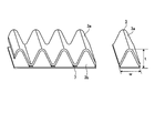
- FIG. 3 is a perspective view of the spacing member.
- FIG. 4 is a perspective view showing an intermediate product formed by connecting the spacing members and one spacing member separated from the intermediate product.
- FIG. 5 is a schematic structural view of a single-stage cardboard processing machine for producing an intermediate product of a spacing member.
- FIG. 6 is a perspective view of a roll coater that applies an adhesive to the spacing member.
- FIG. 7 is a cross-sectional view showing the relationship between the sheet thickness used for the spacing member and the flow path area.
- FIG. 1 is a perspective view of a total heat exchange element according to Embodiment 1 of the present invention.
- the total heat exchange element 50 is configured by laminating a plurality of unit constituent members 10 while changing the direction by 90 degrees.
- One unit constituting member 10 is composed of a partition member 2 and a hollow cylindrical spacing member 3 having a triangular cross section fixed in parallel to the main surface of the partition member 2.
- the interval holding member 3 holds an interval between two partition members 2 adjacent in the stacking direction and forms a flow path between the two partition members 2.
- the flow paths are alternately formed 90 degrees in the stacking direction, and two kinds of fluids (for example, gases such as air) are supplied to the flow paths from different directions as indicated by arrows in FIG.
- the total heat exchange is performed between the two kinds of fluids through the partition member 2.
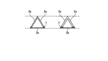
- FIG. 2 is a cross-sectional view showing the configuration of the unit component member 10 constituting the total heat exchange element 50.
- FIG. 3 is a perspective view of the spacing member 3.
- the partition member 2 is made of a material having heat conductivity, moisture permeability, and gas shielding properties.
- the spacing member 3 has a hollow cylindrical shape with a triangular cross section extending substantially parallel to the surface of the partition member 2. Of the three wall surfaces constituting the hollow cylindrical shape having a triangular cross section of the spacing member 3, one wall surface constitutes a superposed wall 3 b that is fixed to the partition member 2.
- the two support walls 3a are produced by bending a sheet-like material into two.
- the bent support wall 3a and the overlapped wall 3b are fixed to each other by an adhesive (third adhesive) 7 applied to the side to form a cylindrical spacing member 3 (FIG. 3).
- the spacing member 3 is fixed by bonding the overlapping wall 3b to the partition member 2 with an adhesive (first adhesive) 5 having moisture permeability.
- the thickness of the overlapping wall 3b of the spacing member 3 is smaller than the thickness of the support wall 3a.
- the two unit constituent members 10 that overlap in the stacking direction are divided into the top of the hollow cylindrical spacing member 3 having a triangular cross section (the bent portion of the support wall 3a) and the partition member of another unit constituent member 10 adjacent to the upper side in the stacking direction.
- the back surface of 2 is adhered and laminated by an adhesive (second adhesive) 6.
- the interval holding member 3 of the present embodiment is formed in a hollow cylindrical shape having a triangular cross section composed of one overlap wall 3b and two support walls 3a.
- the shape of the interval holding member 3 is as follows. It is not limited to such a triangular cross section, and may be a hollow cylindrical shape having a polygonal cross section including the overlapping wall 3b and the supporting wall 3a, for example, a pair of facing overlapping walls 3b and a pair of facing supporting walls. It may be a hollow cylinder having a square cross section composed of 3a.
- FIG. 4 is a perspective view showing an intermediate product formed by connecting the interval holding members 3 and a state of one interval holding member 3 separated from the intermediate products.
- FIG. 5 is a schematic structural view of a single-stage cardboard processing machine for producing an intermediate product of a spacing member. Production of a single-sided cardboard for packing a sheet-like material to be the support wall 3a of the spacing member 3 and a sheet-like material to be the polymerization wall 3b (thickness is smaller than the sheet-like material to be the support wall 3a) An intermediate product of a connected body in which a large number of hollow spacing members 3 as shown in FIG.
- the intermediate spacing product 3 is appropriately cut along the mountain to obtain a hollow spacing member 3.
- the shape of the support wall 3a is corrugated, but the spacing member 3 is fabricated as a hollow shape having a generally triangular cross section.
- the corrugated support wall 3a is formed by the gears h1 and h2, the adhesive 7 is applied to the roller r1, and the overlapping wall 3b is bonded to the roller r2.
- the triangle of the spacing member 3 manufactured using a general corrugated cardboard manufacturing machine has a ratio of height t ⁇ bottom width w of about 0.3 to 0.5. (FIG. 4).
- the interval holding member 3 is produced by using a general corrugated cardboard manufacturing machine in this way, the interval of the overlapping wall 3b, which is a feature of the present embodiment, is smaller than the thickness of the support wall 3a.
- the member 3 can be manufactured easily.
- the adhesive 5 having moisture permeability is applied to the overlapping wall 3b of the hollow spacing member 3 produced as described above and adhered to the partition member 2.
- FIG. 6 is a perspective view of a roll coater that applies the adhesive 5 to the spacing member 3.
- the adhesive 5 stored in the liquid reservoir is uniformly applied to the back surface of the overlapping wall 3b of the spacing member 3.
- the adhesive 5 is first applied to the overlapping wall 3b of the connected spacing member 3, and then the partitioning is performed. It is good also as a procedure which cuts off interval maintenance member 3 before adhering to member 2.
- Examples of the moisture-permeable adhesive 5 used for bonding the partition member 2 and the spacing member 3 include water-soluble resin emulsion adhesive, water-soluble deliquescent alkali metal salt, and deliquescent alkaline earth metal salt. One or a mixture thereof is used.
- the total heat exchange element for air conditioning mainly uses lithium chloride, calcium chloride, etc., which are highly hygroscopic. Others can be expected to be effective if they have moisture permeability, but especially those that contain water-soluble moisture absorbents, in addition to the moisture permeability of the adhesive itself, absorb moisture with water when the adhesive is applied to the spacing member 3. Since the agent quickly penetrates into the spacing member 3 itself, the moisture permeability of the material itself on the spacing member 3 side can be improved, and the moisture permeability of the bonded portion is easily developed.
- the partition member 2 is not particularly limited as long as it can satisfy heat transfer properties, gas shielding properties, and moisture permeability at the same time.
- the total heat exchange element is substantially made by using specially processed paper that has gas shielding properties and moisture permeability by including a water-soluble resin or a water-soluble moisture absorbent, or wood pulp that has been thoroughly beaten. It is known that a specially processed paper having no holes through which air flows is added with a hygroscopic agent, and that a porous thin cloth or nonwoven fabric is bonded to a resin thin film in which the resin itself has moisture permeability. Due to temperature changes during heat exchange, the element may cause condensation inside the element depending on the operating environment, but it may cause various product defects when drooping to the outside, so the material should be water-absorbing. .
- the material of the support wall 3a that does not come into contact with the partition member 2 of the hollow spacing member 3 serves to hold the spacing between the partition members 2, so that it is desirable that the shape is not easily deformed as much as possible.
- the bending rigidity of the sheet-like material is generally known to be proportional to the cube of the thickness in the bending direction when considered as an elastic body, and a material having a large plate thickness is suitable in that respect.
- interval holding member 3 is used is contrary to the reduction of. Accordingly, a thickness of about 60 ⁇ m to 200 ⁇ m is suitable.
- the overlapping wall 3b of the hollow spacing member 3 is a material that does not obstruct the heat transfer and moisture permeability of the partition member 2 as much as possible. Since the gas shielding property for preventing gas transfer between two circulating fluids can be ensured by the partition member 2 and is not necessary, the porous material is preferable because it does not hinder the flow of humidity. In the present embodiment, therefore, an adhesive having moisture permeability is used. In the case of an adhesive using moisture resistance between the material and the partition member 2 and an adhesive using a water-soluble moisture absorbent, the book by penetration of the moisture absorbent is used. It is intended to reduce the moisture permeability resistance of the material itself.
- the adhesive 7 (third adhesive) used when the support wall 3a and the polymerization wall 3b are bonded together to produce the hollow spacing member 3.
- an adhesive containing a water-soluble hygroscopic agent is used as a moisture-permeable adhesive for bonding the spacing member 3 and the partition member 2
- the spacing wall 3 3 is bonded to the support wall 3a and the overlapping wall 3b.
- an adhesive that does not transmit moisture after drying is used as the adhesive 7 used for producing the moisture, the moisture or the moisture absorbent itself does not contact the partition member 2 of the spacing member 3 when the moisture-permeable adhesive is applied.
- the portion to be laminated and bonded has the effect of improving the moisture permeability more than before.
- the amount of the hygroscopic agent of the entire element increases too much, dielectric drying cannot be performed, so that it has moisture permeability used when bonding other parts (for example, the partition member 2 or the partition member 2 and the spacing member 3). It is necessary to adjust by reducing the amount of the hygroscopic agent added to the adhesive.
- the partition member 2 has a specially processed paper (basis weight of 40 g / gram) that is devised so that the Gurley ventilation resistance of JIS P8117, which is a measure of gas shielding properties, is secured for 200 seconds or more by a method such as beating the pulp sufficiently.
- m2 and a thickness of about 50 ⁇ m were used, in which about 8 g / m2 of water-soluble and deliquescent lithium chloride as a moisture absorbent was impregnated.
- a common white glossy high-quality paper (basis weight of about 80 g / m ⁇ 2>, thickness of about 100 [mu] m) is used as the material of the support wall (corrugated) 3a that does not come into contact with the partition member of the hollow spacing member 3, and the partition member 2
- porous specially processed paper having a basis weight of about 20 g / m 2 , a thickness of about 30 ⁇ m, and a Gurley ventilation resistance of 20 seconds or less is used as the raw material of the polymer wall 3b. 5 using a one-stage processing machine as shown in FIG.
- a water-based vinyl acetate resin emulsion (solid content rate of about 15%) is applied to the adhesive 7 at about 15 g / m 2 and adhered, and one of the spacing members 3 is adhered.
- the polymer wall 3 b made of a thin material is water-soluble in a vinyl acetate resin emulsion adhesive containing water as a main solvent as a moisture-permeable adhesive 5.
- the interval x (FIG. 2) of the interval holding member 3 on the partition member 2 is set such that when the dimension in the direction horizontal to the partition member 2 of the interval holding member 3 is a width w, the adjacent interval holding members 3 are adjacent to each other.
- the gap holding member 3 was arranged and bonded so that the gap of the width w also became the width w.
- the unit constituent member 10 formed in this way is laminated by applying a water-based vinyl acetate resin emulsion on the top of each spacing member 3 on the unit constituent member 10 using a roll coater, and laminating and adhering while rotating 90 degrees. The entire element was dried using a dielectric dryer.
- Comparative Example 1 the same material as in Example 1 is used as the material for the partition member 2 and the spacing member 3, and the spacing member 3 has the same outer shape as in Example 1 and is not hollow and solid. did. That is, from the configuration of the first embodiment, the spacing member 3 has the same outer shape and is not hollow but solid. All adhesives were non-moisture permeable adhesives.
- Comparative Example 2 from the configuration of Example 1, the arrangement interval of the hollow interval holding member 3 was set to 0.5 w.
- Comparative Example 3 from the configuration of Comparative Example 2, the spacing member 3 is solid with the same external shape, not hollow. All adhesives were non-moisture permeable adhesives.
- Example 2 from the configuration of Example 1, the interval between the hollow spacing members 3 was set to 2w.
- Example 3 from the configuration of Example 1, the interval between the hollow spacing members 3 was set to 3w.
- Comparative Example 7 from the configuration of Comparative Example 6, the spacing member 3 was solid with the same external shape, not hollow. All adhesives were non-moisture permeable adhesives.
- Comparative Example 8 the same material (same thickness) as that of the support wall 3a of the portion not in contact with the partition member 2 is used for the overlapping wall 3b in contact with the partition member 2 of the hollow spacing member 3.
- the amount of the hygroscopic agent added to the adhesive 5 used for bonding the spacing member 3 and the partition member 2 was increased by the weight increase ratio of the paper of the polymerization wall 3b.
- the other configurations were the same as those in Example 1.
- an adhesive having moisture permeability is used for the adhesive 6 for laminating adhesion, and instead, the amount of the hygroscopic agent for the entire element is made the same as that of the first embodiment.
- the moisture-absorbing material added to the adhesive 5 used for bonding was reduced.
- the other configuration was the same shape and material as in Example 1.
- a hollow spacing member 3 having the same outer dimensions and the same material as in Example 1 was arranged without a gap. That is, the arrangement interval of the hollow interval holding member 3 was set to zero. In other words, this configuration has a conventional general corrugated fin-shaped spacing member.
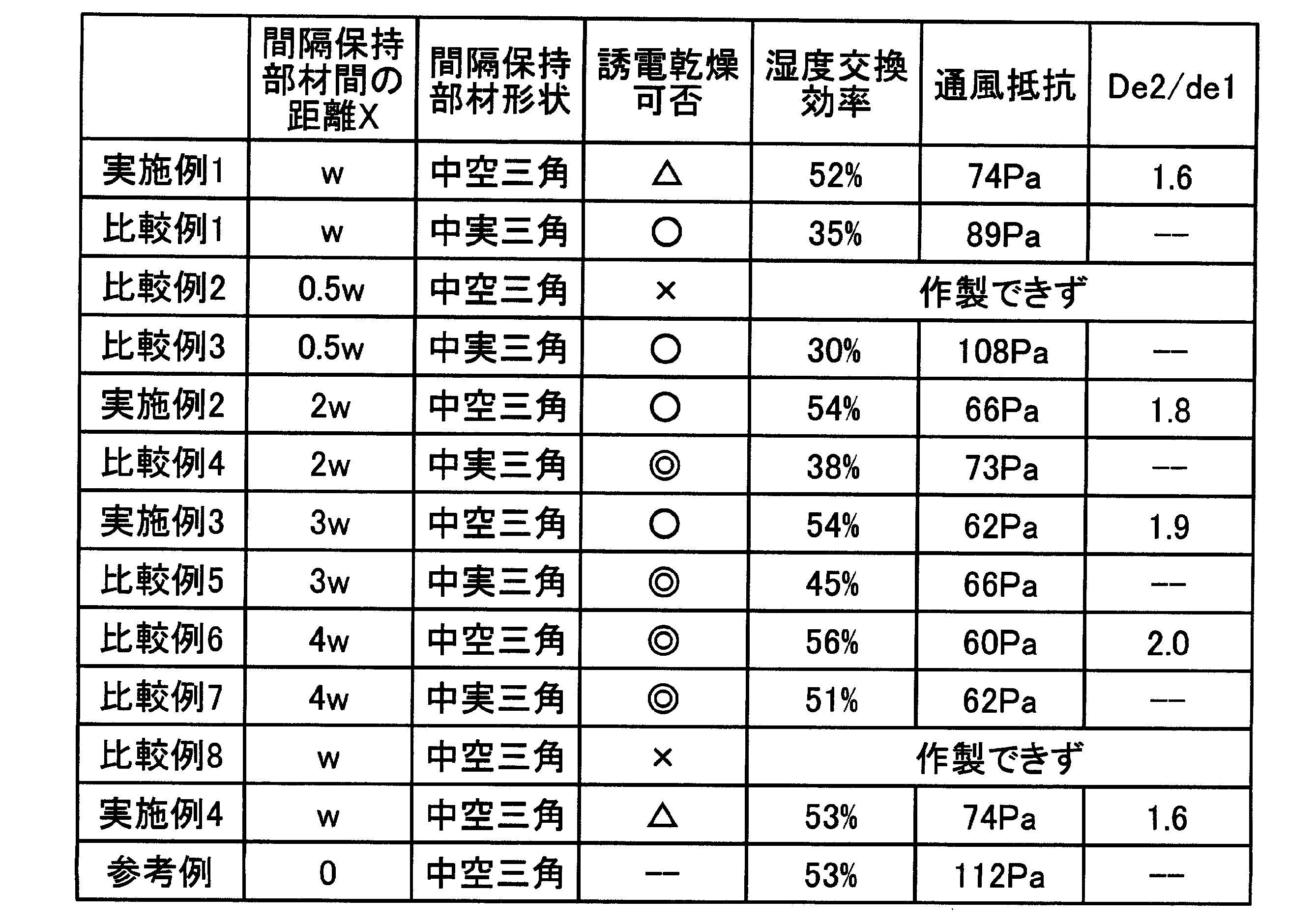
- Table 1 summarizes the dielectric drying availability at the time of manufacturing the devices obtained in the above Examples and Comparative Examples, the humidity exchange efficiency of each device, and the ventilation resistance.
- Examples 1 to 3 using a moisture-permeable adhesive for the hollow spacing member 3 enable dielectric drying when the spacing is greater than or equal to w compared to the other comparative examples.
- the ventilation resistance is lower and the efficiency is higher than the element using the solid spacing member.
- the airflow resistance decreases as the distance between the distance holding members 3 is increased, whether hollow or solid, but since the degree of decrease is different, when the distance between the distance holding members 3 is 4 w, the airflow resistance between the hollow and the solid is almost zero. No change (difference is less than 5%).
- the ratio de2 / de1 between de1 and de2 is preferably in the range of 1.6 or more and less than 2.
- Example 4 the humidity exchange efficiency of Example 4 is slightly improved even though the amount of the hygroscopic agent is almost the same. This is because a hygroscopic agent was added also to the lamination side, so that the hygroscopic agent easily penetrated into the lamination side adhesive and the paper of the bonded portion, and the moisture permeability was improved.
- the present invention can be applied to various forms of the total heat exchange element, and an effect can be expected.
- it is ideal for heat exchange ventilators that ventilate moving bodies such as automobiles and trains, etc.
- total heat exchange that simultaneously exchanges latent heat and sensible heat It is suitable for devices in various fields using
Landscapes
- Engineering & Computer Science (AREA)
- Physics & Mathematics (AREA)
- Thermal Sciences (AREA)
- Mechanical Engineering (AREA)
- General Engineering & Computer Science (AREA)
- Heat-Exchange Devices With Radiators And Conduit Assemblies (AREA)
- Drying Of Gases (AREA)
Abstract
Description
1.6 ≦ de2/de1 < 2
となるような間隔で間隔保持部材が配置されていることを特徴とする。
図1は、本発明の実施の形態1の全熱交換素子の斜視図である。全熱交換素子50は、複数個の単位構成部材10が90度ずつ向きを変えながら積層されて構成されている。1個の単位構成部材10は、仕切部材2と、この仕切部材2の主面に平行に並べて固着された断面三角形の中空筒形の間隔保持部材3とから構成される。間隔保持部材3は、積層方向に隣接する2枚の仕切部材2間の間隔を保持するとともに、2枚の仕切部材2間に流路を形成する。この流路は、積層方向に90度ずつ互い違いに形成されることとなり、この流路に、図1中矢印にて示すように、異なる方向から二種の流体(例えば、空気等の気体)を通過させ、仕切部材2を介して二種の流体間で全熱交換する。
3 間隔保持部材
3a 間隔保持部材の支持壁
3b 間隔保持部材の重合壁
5 接着剤(第1の接着剤)
6 接着剤(第2の接着剤)
7 接着剤(第3の接着剤)
10 単位構成部材
50 全熱交換素子
Claims (6)
- 仕切部材と間隔保持部材と有する単位構成部材を交互に向きを変えて積層し、前記仕切部材間に前記間隔保持部材によって間隔が保持された流路を形成し、隣接する前記流路に二種の流体を通過させ、前記仕切部材を介して前記二種の流体間で熱交換する全熱交換素子において、
前記仕切部材は、伝熱性、透湿性および気体遮蔽性を有しており、
前記間隔保持部材は、前記仕切部材の面に沿って概略平行に延びる断面多角形の中空筒形を成し、前記仕切部材と重なる重合壁と、この重合壁の側端から立ち上がり積層方向上下の前記仕切部材間に立設されて間隔を保持する支持壁とを含んで構成され、
前記重合壁は、前記支持壁より厚さが小さく、透湿性を有する第1の接着剤にて前記仕切部材に貼り合わされている
ことを特徴とする全熱交換素子。 - 前記間隔保持部材は、1枚の前記重合壁と2枚の前記支持壁とから成る断面三角形の中空筒形に形成され、
前記間隔保持部材内部の流路断面の等価直径de1と、隣り合う2つの前記間隔保持部材と積層方向上下2枚の前記仕切部材とで形成される流路断面の等価直径de2との関係が
1.6 ≦ de2/de1 < 2
となるような間隔で前記間隔保持部材が配置されている
ことを特徴とする請求項1に記載の全熱交換素子。 - 前記単位構成部材を積層接着する接着剤であり、前記断面三角形の中空筒形の間隔保持部材の頂部と積層方向に隣接する前記単位構成部材の前記仕切部材とを接着する第2の接着剤として、透湿性を有する接着剤を用いる
ことを特徴とする請求項2に記載の全熱交換素子。 - 前記仕切部材及び前記間隔保持部材の素材として、吸液性を有する素材を用い、前記第1の接着剤及び第2の接着剤として、水を主溶媒とする樹脂エマルジョン接着剤に水溶性の吸湿剤を混合したものを用いる
ことを特徴とする請求項3に記載の全熱交換素子。 - 前記水溶性の吸湿剤として、潮解性アルカリ金属塩、潮解性アルカリ土類金属塩のいずれか一つ又はそれらを混合したものを用いる
ことを特徴とする請求項4に記載の全熱交換素子。 - 前記支持壁と前記重合壁とを接着する第3の接着剤として、接着完了後実質的に透湿性が無くなる接着剤を用いる
ことを特徴とする請求項1に記載の全熱交換素子。
Priority Applications (6)
| Application Number | Priority Date | Filing Date | Title |
|---|---|---|---|
| JP2011531699A JPWO2011033624A1 (ja) | 2009-09-16 | 2009-09-16 | 全熱交換素子 |
| PCT/JP2009/066163 WO2011033624A1 (ja) | 2009-09-16 | 2009-09-16 | 全熱交換素子 |
| CN2009801604913A CN102472601B (zh) | 2009-09-16 | 2009-09-16 | 全热交换元件 |
| US13/496,055 US20120168136A1 (en) | 2009-09-16 | 2009-09-16 | Total heat exchange element |
| KR1020117030973A KR20120023132A (ko) | 2009-09-16 | 2009-09-16 | 전열교환 소자 |
| EP09849483.4A EP2472210B1 (en) | 2009-09-16 | 2009-09-16 | Total enthalpy heat exchange element |
Applications Claiming Priority (1)
| Application Number | Priority Date | Filing Date | Title |
|---|---|---|---|
| PCT/JP2009/066163 WO2011033624A1 (ja) | 2009-09-16 | 2009-09-16 | 全熱交換素子 |
Publications (1)
| Publication Number | Publication Date |
|---|---|
| WO2011033624A1 true WO2011033624A1 (ja) | 2011-03-24 |
Family
ID=43758251
Family Applications (1)
| Application Number | Title | Priority Date | Filing Date |
|---|---|---|---|
| PCT/JP2009/066163 Ceased WO2011033624A1 (ja) | 2009-09-16 | 2009-09-16 | 全熱交換素子 |
Country Status (6)
| Country | Link |
|---|---|
| US (1) | US20120168136A1 (ja) |
| EP (1) | EP2472210B1 (ja) |
| JP (1) | JPWO2011033624A1 (ja) |
| KR (1) | KR20120023132A (ja) |
| CN (1) | CN102472601B (ja) |
| WO (1) | WO2011033624A1 (ja) |
Cited By (6)
| Publication number | Priority date | Publication date | Assignee | Title |
|---|---|---|---|---|
| WO2015050104A1 (ja) * | 2013-10-02 | 2015-04-09 | 東レ株式会社 | 熱交換用原紙およびそれを用いた全熱交換素子 |
| JP2016011796A (ja) * | 2014-06-30 | 2016-01-21 | 三菱電機株式会社 | 熱交換換気装置 |
| WO2019124286A1 (ja) * | 2017-12-22 | 2019-06-27 | パナソニックIpマネジメント株式会社 | 熱交換素子とそれを用いた熱交換形換気装置 |
| JP2019113238A (ja) * | 2017-12-22 | 2019-07-11 | パナソニックIpマネジメント株式会社 | 熱交換素子とそれを用いた熱交換形換気装置 |
| JP7389514B1 (ja) | 2022-08-02 | 2023-11-30 | 株式会社テクノフロンティア | 熱交換素子 |
| JP7428421B1 (ja) | 2022-08-23 | 2024-02-06 | 株式会社テクノフロンティア | 熱交換素子 |
Families Citing this family (10)
| Publication number | Priority date | Publication date | Assignee | Title |
|---|---|---|---|---|
| KR101579141B1 (ko) | 2008-04-18 | 2015-12-21 | 스벤 멜커 닐손 | 채널 시스템 |
| SE533453C2 (sv) | 2008-08-06 | 2010-10-05 | Sven Melker Nilsson | Kanalsystem |
| US20140150998A1 (en) * | 2012-11-27 | 2014-06-05 | Air Change Pty Limited | Heat exchanger |
| CN103233399B (zh) * | 2013-04-11 | 2016-08-17 | 广东华凯科技股份有限公司 | 一种乳胶纤维板保水处理剂及其制备方法和保水方法 |
| CN105874295A (zh) * | 2013-12-26 | 2016-08-17 | 东丽株式会社 | 全热交换元件的制造方法和全热交换元件 |
| KR102223356B1 (ko) * | 2020-07-13 | 2021-03-05 | 송길섭 | 대향류 전열교환기의 제조방법 |
| EP4343259B1 (en) * | 2020-08-21 | 2025-02-26 | Mitsubishi Electric Corporation | Heat exchange element and heat exchange ventilation device |
| JP7786033B2 (ja) * | 2020-09-17 | 2025-12-16 | 王子ホールディングス株式会社 | 間隔部材用シート及び全熱交換素子 |
| FR3130359B1 (fr) * | 2021-12-13 | 2024-04-26 | Liebherr Aerospace Toulouse Sas | Dispositif d’échange thermique comprenant au moins un dispositif limiteur de débit, système de conditionnement d’air et véhicule |
| CN116518472B (zh) * | 2023-04-25 | 2025-11-25 | 广东摩多未来科技有限公司 | 除湿转轮及除湿机 |
Citations (11)
| Publication number | Priority date | Publication date | Assignee | Title |
|---|---|---|---|---|
| JPS6174787U (ja) * | 1984-10-19 | 1986-05-20 | ||
| JPS6245583A (ja) | 1985-08-26 | 1987-02-27 | Nippon Oil & Fats Co Ltd | 含フツ素複素環化合物の製造法 |
| JPS6245583U (ja) * | 1985-09-05 | 1987-03-19 | ||
| JPH03113292A (ja) | 1989-09-27 | 1991-05-14 | Matsushita Electric Ind Co Ltd | 熱交換器 |
| JPH0424492A (ja) | 1990-05-21 | 1992-01-28 | Matsushita Electric Ind Co Ltd | 熱交換素子 |
| JP2001147092A (ja) | 1999-11-19 | 2001-05-29 | Toray Eng Co Ltd | 熱交換セグメント及びそれを積層した気体対気体用熱交換素子 |
| JP3414012B2 (ja) | 1994-12-26 | 2003-06-09 | ダイキン工業株式会社 | 熱交換エレメント |
| JP2005140362A (ja) | 2003-11-05 | 2005-06-02 | Matsushita Electric Ind Co Ltd | 熱交換器 |
| JP2007315649A (ja) | 2006-05-24 | 2007-12-06 | Mitsubishi Electric Corp | 全熱交換器 |
| JP2008041327A (ja) | 2006-08-02 | 2008-02-21 | Showa Denko Kk | マスクおよびマスクを使用した表示素子ならびにマスクを使用した表示素子の製造方法 |
| WO2008041327A1 (fr) * | 2006-10-03 | 2008-04-10 | Mitsubishi Electric Corporation | Élément d'échange thermique total et appareil d'échange thermique total |
Family Cites Families (10)
| Publication number | Priority date | Publication date | Assignee | Title |
|---|---|---|---|---|
| US2985434A (en) * | 1957-03-15 | 1961-05-23 | Air Preheater | Regenerator |
| CH382200A (de) * | 1961-02-27 | 1964-09-30 | Franklin Dipl Ing Froehlich | Wärmeaustauscher |
| JPH0610588B2 (ja) * | 1984-12-26 | 1994-02-09 | 三菱電機株式会社 | 熱交換器 |
| JPH0612215B2 (ja) * | 1985-01-09 | 1994-02-16 | 三菱電機株式会社 | 熱交換器 |
| TW224508B (ja) * | 1991-03-15 | 1994-06-01 | Toshiba Co Ltd | |
| ATE502263T1 (de) * | 2002-07-22 | 2011-04-15 | Daikin Ind Ltd | Entfeuchtungselement und f r dieses verwendetes absorbierelement |
| AU2002320690B2 (en) * | 2002-07-24 | 2007-03-29 | Daikin Industries, Ltd. | Dehumidifying element |
| CN2752702Y (zh) * | 2004-06-23 | 2006-01-18 | 丁宏广 | 空气全热交换器 |
| US7320361B2 (en) * | 2005-10-28 | 2008-01-22 | Mitsubishi Denki Kabushiki Kaisha | Heat exchanger |
| CN101059263A (zh) * | 2006-04-17 | 2007-10-24 | 煜丰科技股份有限公司 | 机能式全热交换系统 |
-
2009
- 2009-09-16 WO PCT/JP2009/066163 patent/WO2011033624A1/ja not_active Ceased
- 2009-09-16 CN CN2009801604913A patent/CN102472601B/zh not_active Expired - Fee Related
- 2009-09-16 EP EP09849483.4A patent/EP2472210B1/en not_active Not-in-force
- 2009-09-16 JP JP2011531699A patent/JPWO2011033624A1/ja active Pending
- 2009-09-16 US US13/496,055 patent/US20120168136A1/en not_active Abandoned
- 2009-09-16 KR KR1020117030973A patent/KR20120023132A/ko not_active Ceased
Patent Citations (11)
| Publication number | Priority date | Publication date | Assignee | Title |
|---|---|---|---|---|
| JPS6174787U (ja) * | 1984-10-19 | 1986-05-20 | ||
| JPS6245583A (ja) | 1985-08-26 | 1987-02-27 | Nippon Oil & Fats Co Ltd | 含フツ素複素環化合物の製造法 |
| JPS6245583U (ja) * | 1985-09-05 | 1987-03-19 | ||
| JPH03113292A (ja) | 1989-09-27 | 1991-05-14 | Matsushita Electric Ind Co Ltd | 熱交換器 |
| JPH0424492A (ja) | 1990-05-21 | 1992-01-28 | Matsushita Electric Ind Co Ltd | 熱交換素子 |
| JP3414012B2 (ja) | 1994-12-26 | 2003-06-09 | ダイキン工業株式会社 | 熱交換エレメント |
| JP2001147092A (ja) | 1999-11-19 | 2001-05-29 | Toray Eng Co Ltd | 熱交換セグメント及びそれを積層した気体対気体用熱交換素子 |
| JP2005140362A (ja) | 2003-11-05 | 2005-06-02 | Matsushita Electric Ind Co Ltd | 熱交換器 |
| JP2007315649A (ja) | 2006-05-24 | 2007-12-06 | Mitsubishi Electric Corp | 全熱交換器 |
| JP2008041327A (ja) | 2006-08-02 | 2008-02-21 | Showa Denko Kk | マスクおよびマスクを使用した表示素子ならびにマスクを使用した表示素子の製造方法 |
| WO2008041327A1 (fr) * | 2006-10-03 | 2008-04-10 | Mitsubishi Electric Corporation | Élément d'échange thermique total et appareil d'échange thermique total |
Non-Patent Citations (1)
| Title |
|---|
| See also references of EP2472210A4 * |
Cited By (9)
| Publication number | Priority date | Publication date | Assignee | Title |
|---|---|---|---|---|
| WO2015050104A1 (ja) * | 2013-10-02 | 2015-04-09 | 東レ株式会社 | 熱交換用原紙およびそれを用いた全熱交換素子 |
| JPWO2015050104A1 (ja) * | 2013-10-02 | 2017-03-09 | 東レ株式会社 | 熱交換用原紙およびそれを用いた全熱交換素子 |
| JP2016011796A (ja) * | 2014-06-30 | 2016-01-21 | 三菱電機株式会社 | 熱交換換気装置 |
| WO2019124286A1 (ja) * | 2017-12-22 | 2019-06-27 | パナソニックIpマネジメント株式会社 | 熱交換素子とそれを用いた熱交換形換気装置 |
| JP2019113238A (ja) * | 2017-12-22 | 2019-07-11 | パナソニックIpマネジメント株式会社 | 熱交換素子とそれを用いた熱交換形換気装置 |
| JP7389514B1 (ja) | 2022-08-02 | 2023-11-30 | 株式会社テクノフロンティア | 熱交換素子 |
| JP2024020775A (ja) * | 2022-08-02 | 2024-02-15 | 株式会社テクノフロンティア | 熱交換素子 |
| JP7428421B1 (ja) | 2022-08-23 | 2024-02-06 | 株式会社テクノフロンティア | 熱交換素子 |
| JP2024030057A (ja) * | 2022-08-23 | 2024-03-07 | 株式会社テクノフロンティア | 熱交換素子 |
Also Published As
| Publication number | Publication date |
|---|---|
| EP2472210A4 (en) | 2014-12-31 |
| US20120168136A1 (en) | 2012-07-05 |
| CN102472601B (zh) | 2013-12-25 |
| JPWO2011033624A1 (ja) | 2013-02-07 |
| EP2472210B1 (en) | 2016-07-20 |
| CN102472601A (zh) | 2012-05-23 |
| EP2472210A1 (en) | 2012-07-04 |
| KR20120023132A (ko) | 2012-03-12 |
Similar Documents
| Publication | Publication Date | Title |
|---|---|---|
| WO2011033624A1 (ja) | 全熱交換素子 | |
| JP4206894B2 (ja) | 全熱交換素子 | |
| US8726978B2 (en) | Heat exchanger element and heat exchanger | |
| JP5110641B2 (ja) | 全熱交換器 | |
| EP2851642B1 (en) | Heat-exchange element and air conditioner | |
| CN102414534A (zh) | 全热交换元件 | |
| JP4874389B2 (ja) | 全熱交換素子の製造方法および全熱交換素子 | |
| KR20180111788A (ko) | 엔탈피 교환기 | |
| WO2013157056A1 (ja) | 熱交換素子 | |
| JP2011237157A (ja) | 熱交換器の全熱交換エレメント | |
| WO2019180834A1 (ja) | 全熱交換素子および全熱交換器 | |
| JP5610777B2 (ja) | 全熱交換素子 | |
| JP4928295B2 (ja) | 顕熱交換素子 | |
| KR101443053B1 (ko) | 현열 교환 소자 | |
| JPH08313186A (ja) | 熱交換器 | |
| JP2008070070A (ja) | 全熱交換器 | |
| JP4305530B2 (ja) | 熱交換器 | |
| JP7126617B2 (ja) | 熱交換素子および熱交換換気装置 | |
| JPWO2013157055A1 (ja) | 熱交換素子及び空気調和装置 | |
| JP2005291527A (ja) | 熱交換基板の製造方法 | |
| KR20200102664A (ko) | 타공부를 갖는 전열 교환 소자 | |
| JPH0650693A (ja) | 熱交換機エレメント | |
| JP2019158319A (ja) | 全熱交換素子及び全熱交換器 | |
| JP2005291529A (ja) | 熱交換基板 |
Legal Events
| Date | Code | Title | Description |
|---|---|---|---|
| WWE | Wipo information: entry into national phase |
Ref document number: 200980160491.3 Country of ref document: CN |
|
| 121 | Ep: the epo has been informed by wipo that ep was designated in this application |
Ref document number: 09849483 Country of ref document: EP Kind code of ref document: A1 |
|
| WWE | Wipo information: entry into national phase |
Ref document number: 2011531699 Country of ref document: JP |
|
| ENP | Entry into the national phase |
Ref document number: 20117030973 Country of ref document: KR Kind code of ref document: A |
|
| REEP | Request for entry into the european phase |
Ref document number: 2009849483 Country of ref document: EP |
|
| WWE | Wipo information: entry into national phase |
Ref document number: 2009849483 Country of ref document: EP |
|
| WWE | Wipo information: entry into national phase |
Ref document number: 13496055 Country of ref document: US |
|
| NENP | Non-entry into the national phase |
Ref country code: DE |