WO2011052182A1 - Dispositif de traitement par fermentation/décomposition - Google Patents
Dispositif de traitement par fermentation/décomposition Download PDFInfo
- Publication number
- WO2011052182A1 WO2011052182A1 PCT/JP2010/006308 JP2010006308W WO2011052182A1 WO 2011052182 A1 WO2011052182 A1 WO 2011052182A1 JP 2010006308 W JP2010006308 W JP 2010006308W WO 2011052182 A1 WO2011052182 A1 WO 2011052182A1
- Authority
- WO
- WIPO (PCT)
- Prior art keywords
- decomposition treatment
- treatment tank
- decomposition
- dropping
- recess
- Prior art date
- Legal status (The legal status is an assumption and is not a legal conclusion. Google has not performed a legal analysis and makes no representation as to the accuracy of the status listed.)
- Ceased
Links
Images


Classifications
-
- C—CHEMISTRY; METALLURGY
- C02—TREATMENT OF WATER, WASTE WATER, SEWAGE, OR SLUDGE
- C02F—TREATMENT OF WATER, WASTE WATER, SEWAGE, OR SLUDGE
- C02F11/00—Treatment of sludge; Devices therefor
- C02F11/02—Biological treatment
-
- C—CHEMISTRY; METALLURGY
- C05—FERTILISERS; MANUFACTURE THEREOF
- C05F—ORGANIC FERTILISERS NOT COVERED BY SUBCLASSES C05B, C05C, e.g. FERTILISERS FROM WASTE OR REFUSE
- C05F17/00—Preparation of fertilisers characterised by biological or biochemical treatment steps, e.g. composting or fermentation
- C05F17/90—Apparatus therefor
- C05F17/921—Devices in which the material is conveyed essentially horizontally between inlet and discharge means
- C05F17/939—Means for mixing or moving with predetermined or fixed paths, e.g. rails or cables
-
- C—CHEMISTRY; METALLURGY
- C05—FERTILISERS; MANUFACTURE THEREOF
- C05F—ORGANIC FERTILISERS NOT COVERED BY SUBCLASSES C05B, C05C, e.g. FERTILISERS FROM WASTE OR REFUSE
- C05F17/00—Preparation of fertilisers characterised by biological or biochemical treatment steps, e.g. composting or fermentation
- C05F17/90—Apparatus therefor
- C05F17/964—Constructional parts, e.g. floors, covers or doors
-
- Y—GENERAL TAGGING OF NEW TECHNOLOGICAL DEVELOPMENTS; GENERAL TAGGING OF CROSS-SECTIONAL TECHNOLOGIES SPANNING OVER SEVERAL SECTIONS OF THE IPC; TECHNICAL SUBJECTS COVERED BY FORMER USPC CROSS-REFERENCE ART COLLECTIONS [XRACs] AND DIGESTS
- Y02—TECHNOLOGIES OR APPLICATIONS FOR MITIGATION OR ADAPTATION AGAINST CLIMATE CHANGE
- Y02P—CLIMATE CHANGE MITIGATION TECHNOLOGIES IN THE PRODUCTION OR PROCESSING OF GOODS
- Y02P20/00—Technologies relating to chemical industry
- Y02P20/141—Feedstock
- Y02P20/145—Feedstock the feedstock being materials of biological origin
-
- Y—GENERAL TAGGING OF NEW TECHNOLOGICAL DEVELOPMENTS; GENERAL TAGGING OF CROSS-SECTIONAL TECHNOLOGIES SPANNING OVER SEVERAL SECTIONS OF THE IPC; TECHNICAL SUBJECTS COVERED BY FORMER USPC CROSS-REFERENCE ART COLLECTIONS [XRACs] AND DIGESTS
- Y02—TECHNOLOGIES OR APPLICATIONS FOR MITIGATION OR ADAPTATION AGAINST CLIMATE CHANGE
- Y02W—CLIMATE CHANGE MITIGATION TECHNOLOGIES RELATED TO WASTEWATER TREATMENT OR WASTE MANAGEMENT
- Y02W10/00—Technologies for wastewater treatment
- Y02W10/20—Sludge processing
-
- Y—GENERAL TAGGING OF NEW TECHNOLOGICAL DEVELOPMENTS; GENERAL TAGGING OF CROSS-SECTIONAL TECHNOLOGIES SPANNING OVER SEVERAL SECTIONS OF THE IPC; TECHNICAL SUBJECTS COVERED BY FORMER USPC CROSS-REFERENCE ART COLLECTIONS [XRACs] AND DIGESTS
- Y02—TECHNOLOGIES OR APPLICATIONS FOR MITIGATION OR ADAPTATION AGAINST CLIMATE CHANGE
- Y02W—CLIMATE CHANGE MITIGATION TECHNOLOGIES RELATED TO WASTEWATER TREATMENT OR WASTE MANAGEMENT
- Y02W30/00—Technologies for solid waste management
- Y02W30/40—Bio-organic fraction processing; Production of fertilisers from the organic fraction of waste or refuse
Definitions
- the present invention relates to a technical field of a fermentation decomposition treatment apparatus for decomposing sludge such as organic sludge and garbage.
- the stirring apparatus is comprised so that it may stir over the whole region, reciprocatingly reversing the inside of a decomposition treatment tank with a traveling carriage, and in the moving end part of a decomposition treatment tank, stirring is carried out.
- a pressure is applied to press the object to be processed against the side wall on the moving end side of the decomposition treatment tank.
- the material to be treated such as excess sludge has a property of being highly viscous and easily solidified, and is preliminarily coagulated with a coagulant, so that it receives pressure that is pressed against the side wall at the moving end of the decomposition treatment tank.
- a risk of solidifying in a state of attracting the form that is compressed and deposited on the side wall and adhering to the side wall There is a risk of solidifying in a state of attracting the form that is compressed and deposited on the side wall and adhering to the side wall.
- the to-be-processed object solidified with the reciprocating reversal operation of the agitator for a long time accumulates (accumulates) on the side wall, and the moving range of the agitator is narrowed.
- the solidified workpiece is not further decomposed, and as a result, the processing efficiency is greatly reduced, and there is a problem to be solved by the present invention.
- the invention of claim 1 is a product to be stirred put into a box-shaped decomposition treatment tank,
- the stirrer When stirring with a stirrer that reciprocally reverses between a pair of opposing side walls of the decomposition treatment tank, the stirrer has a groove bottom that is lower than the bottom wall of the decomposition treatment tank in the vicinity of each side wall of the decomposition treatment tank.
- the fermentative decomposition treatment apparatus is characterized in that a drop recess that can be discharged to the outside is formed by the object to be stirred pressed against the side wall.
- the dropping recess is formed in the bottom wall of the decomposition treatment tank.
- the fermentative decomposition treatment apparatus according to claim 2, wherein the stirring device is set so as to be positioned immediately above the dropping concave portion at the moving end of the reciprocating reversal movement.
- the invention according to claim 4 is characterized in that the drop recess is formed to have an inclined groove side that becomes lower toward the side wall of the decomposition treatment tank. It is a fermentation decomposition processing apparatus as described in above.
- the fermentative decomposition treatment apparatus is provided with a spraying device for spraying the object to be treated, and the discharging means is a recovery means for transferring the stirring object discharged from the dropping recess to the spraying device.
- the stirring target does not adhere to the side wall and solidifies, and the stirring target in the decomposition treatment tank is It is possible to maintain a high freezing treatment efficiency by maintaining a free flowing state with good fluidity over the entire area.
- adhesion to the side wall and solidification of a to-be-stirred object can be prevented further.
- adhesion to the side wall of a to-be-stirred object and the further prevention of solidification can be aimed at.
- the discharge from the dropping recess can be automatically performed.
- the moisture content of the content in a casing will be reduced, and it will be in the state suitable for dispersion
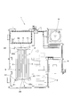
- FIG. 4 is a plan view of FIG. 3. It is a side view explaining the principal part. It is a side view explaining the principal part in 2nd embodiment. It is a side view explaining 3rd embodiment.
- reference numeral 1 denotes a building where a fermentation decomposition apparatus is installed.
- One side of the building 1 (left side in FIG. 1) is constructed at a ceiling height and has a crane device (shown by a chain line in the figure) above and below.
- a decomposition treatment tank 2 that is formed long in the direction and into which an agitated material that is a mixture of a colony (microorganism carrier) and an object to be treated is placed, while the concentrating tank A and electricity are provided on the other side (right side).
- a chamber B is provided, and a deodorizing tank C for processing odor from the decomposition processing tank 2 is provided in front of these chambers (front side in FIG. 2).
- the decomposition treatment tank 2 has a box shape having left and right side walls 3, front and rear side walls 4, and a bottom wall 5.
- a stepped portion 3a projecting inwardly is provided at an intermediate portion of the left and right side walls 3 in the vertical direction.
- the gantry 6 is configured to be supported via a support 3b provided on the upper end surface of the stepped portion 3a.
- the gantry 6 is configured to support the front and rear side walls 4 (main It is configured to move in the front-rear direction along the left and right side walls 3 between the opposing sides (corresponding to a pair of opposing side walls of the invention).
- a stirrer 7 is provided in front of the gantry 6 for agitating the agitated material put into the decomposition treatment tank 2, and behind the gantry 6, the object to be treated and, as will be described later.
- a spraying device 8 is provided for spraying (inputting) the agitated material (collected material) recovered from the decomposition treatment tank 2 into the decomposition treatment tank 2.
- the decomposition treatment tank 2 is provided with a lid 2a in a state along the left and right and upper end edges of the front and rear side walls 3 and 4, and is configured to cover above the stirring device 7 and the spraying device 8 mounted on the gantry 6.
- the devices 7 and 8 are configured to be sealed in the decomposition treatment tank 2.
- the gantry 6 is constituted by a front-rear direction frame 6a facing in the front-rear direction and a left-right direction frame 6b facing in the left-right direction, and a flat plate-like support plate 6c is fixed to the front part. Furthermore, a plurality of agitator mounting brackets 6d adjacent in the left-right direction are fixed to the front portion of the gantry 6 so as to hang downward.
- the stirrer 7 is composed of first and second stirrers 9 and 10 which are arranged adjacent to each other in a line in the left-right direction, and each stirrer 9 and 10 is attached to a support plate 6c on the gantry 6.
- the stirring operation is performed based on the driving of the pair of left and right electric motors 11 fixed.
- the first stirrer 9 positioned on the left side in FIG. 3 includes a main stirrer positioned between the pair of left and right support frames 12 and a sub stirrer positioned outside each support frame 12.
- the second stirrer 10 located on the right side in FIG. 3 includes a main stirrer located between the pair of left and right support frames 12 and a sub-stirrer located outside the right support frame 12.
- the first stirrer 9 will be described below, and the description of the second stirrer 10 will be omitted.
- the first stirrer 9 includes a reinforcing shaft 13 that is supported by the stirrer mounting bracket 6d in a penetrating manner, and the upper ends of the pair of support frames 12 are formed at the penetrating ends of the reinforcing shaft 13.
- the part is pivotally supported so as to be swingable in the front-rear direction.
- a drive shaft 14 positioned above and a driven shaft 15 positioned below are rotatably supported between the support frames 12 and the drive shaft 14 and the electric motor 11 are connected to the chain 11a.
- the drive shaft 14 is configured to rotate forward and backward based on forward and reverse driving of the electric motor 11.
- the drive and driven sprockets 14a and 15a are fixed integrally with the drive and driven shafts 14 and 15 in the state of facing each other in the vertical direction. Three sets of drive and driven sprockets 14a and 15a are fixed in the adjacent state, and one set of drive and driven sprockets 14a and 15a are fixed to the outer sides of the left and right support frames 12, respectively.
- the five chains of driving and driven sprockets 14a and 15a are respectively suspended by operating chains 16, and each operating chain 16 is provided with a plurality of stirring blades 16a positioned at appropriate positions.
- the operating chain 16 is driven based on the rotation of the drive shaft 14 driven by the electric motor 11, and circulates between the driven sprockets 14a and 15a.
- the stirring blade 16a provided on the upper movement side of the operating chain 16 is configured to circulate and move in the direction of the arrow Y (downward).
- the gantry 6 is configured to move in the front-rear direction above the decomposition processing tank 2 by driving a traveling motor 17, and the motor 17 is rotatably supported by the gantry 6 and driven.
- the sprocket 17a is configured to rotate forward and backward via a power transmission mechanism such as chain transmission.
- a traveling gear 17b that rotates in conjunction with the rotation of the driven sprocket 17a is connected to the driven sprocket 17a.
- the traveling gear 17b is provided integrally with the support 3b on the stepped portion 3a of the left and right side walls 3.
- the gantry 6 is configured to move in the front-rear direction by rotating while meshing with the rack 2b.
- the spraying device 8 includes a box-shaped casing 18 that is long in the left-right direction, and an upper end portion of the casing 18 is long open in the left-right direction and is formed in the inlet 18a.
- the casing 18 is provided with a left and right transfer body 18b for transferring the object to be processed and the collected material input from the input port 18a in the left and right direction, and a front and rear transfer body 18c for transferring in the front and rear direction.
- the transfer bodies 18b and 18c are each configured by a spiral transfer body (auger) and are configured to be driven by transfer motors 18d and 18e, respectively.
- recovery material thrown in from the insertion port 18a are set to the decomposition
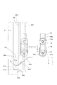
- the drop recessed part 20 by which this invention was implemented is located in the vicinity site
- the drop recesses 20 formed at the front and rear end portions of the decomposition treatment tank 2 are formed in line symmetry, the description here is the drop recess 20 on the front end portion side in front of the drawing in FIG. 3 will be described with reference to FIGS.
- the dropping recess 20 is provided in the entire left and right direction below the front end portion of the decomposition treatment tank 2, and includes a front groove side 20a that is a portion extending downward from the lower end of the front side wall 4 and a bottom wall.
- each drop recess 20 is provided with a discharge means of the present invention so that the agitated object dropped into the drop recess 20 can be discharged from the drop recess 20.
- the discharging means is provided by a pair of left and right left and right transfer bodies 21 provided in spaces surrounded by the front groove side 20a, the groove bottom 20b, and the first rear groove side 20c, which are the groove back sides of the drop recesses 20, respectively. It is configured.
- Each of the left and right transfer bodies 21 is formed in a left and right communication shape, and includes a casing 21a shared by the pair of left and right left and right transfer bodies 21 and a pair of left and right spiral transfer bodies (augers) 21b installed in the casing 21a.
- each of the left and right transfer bodies 21 are disposed so as to protrude left and right through the left and right side walls 3 of the decomposition treatment tank 2.
- the upper end surface 21c of the casing 21a shared by the left and right transfer bodies 21 is formed to be flush with the upper end edge of the first rear groove side 20c.
- an opening 21d is opened.
- the second rear groove side 20d facing the casing upper end surface 21c is positioned at two positions that are adjacent to the three openings 21d in the left-right direction formed in the casing 21a, and forward (
- a guide protrusion 20e having a guide surface that bulges out and is inclined toward each opening 21d is formed.
- the agitated object descending along the second rear groove side 20d is guided by the guide protrusion 20e toward the opening 21d formed in the casing 21b on the groove rear side, and falls into the casing 21b without delay.
- the opening 21d provided in the casing 21a is provided at three places, and the guide protrusions 20e provided between these openings 21d are provided at two places.
- the four openings 21d are provided as guides.
- each of the left and right transfer bodies 21 is configured such that the spiral transfer body 21b is driven by receiving the driving force of the transfer motor 21e provided therein, and each opening 21d is driven in accordance with the drive of each spiral transfer body 21b.
- the object to be stirred that has been dropped into the casing 21a via the gap is transferred to the left and right ends of the casing 21a, that is, to the left and right ends of the dropping recess 20, and discharged from the dropping recess 20. .
- a lower end portion of the upper transfer body 22 corresponding to the recovery means of the present invention is connected to the left and right transfer body 21 protruding from the left and right end portions of the decomposition treatment tank 2.
- the upper transfer body 22 includes a casing 22a extending upward from the upper end surface of the casing 18 of the spraying device 8, and a bucket conveyor 22b.
- the body 22 is in a state of communicating with the lower end front portion of the casing 22a.
- the upper transfer body 22 is configured such that the bucket conveyor 22b performs circulation transfer in the vertical direction in response to the driving force of a motor (not shown) provided in each case.
- the waste discharged to the left and right ends of the casing is transferred to the upper end of the casing 22a.
- a slide-type shooter 22c is connected to the upper end of the casing 22a of each upper transfer body 22, and the tip of the shooter 22c seals an opening formed in the lid 2a of the decomposition treatment tank 2. It penetrates like a stop and extends toward the inlet 18a of the casing 18 of the spraying device 8. And the shooter 22c is comprised so that the discharge
- the agitated object dropped into the drop recess 20 is discharged from the drop recess 20 by the left and right transfer bodies 21 serving as discharge means, and further, the discharged discharge is discharged by the upper transfer body 22 and the shooter 22c.
- the configured recovery means By passing through the configured recovery means, it becomes a recovered product and is transferred to the casing 18 of the spraying device 8 and is again charged (respread) into the decomposition treatment tank 2 as a mixture with the object to be processed in the casing 18. It is comprised so that.
- the recovered material (object to be stirred) dropped from the recess 20 by the left and right transfer body 21 serving as the discharging means can be used as it is, for example, as a fertilizer.
- the gantry 6 performs the agitation operation by the agitator 7 while reciprocally reversing in the front-rear direction along the step portion 3a of the left and right side walls 3 of the decomposition treatment tank 2, but the gantry 6 Is temporarily stopped with the first and second stirrers 9 and 10 of the stirrer 7 approaching either one of the side walls 4 before and after the decomposition treatment tank 2 as the moving end of the reciprocating reversal movement. 7 is also configured to stop the stirring operation. Then, the stop state is continued for a preset waiting time, and then the movement direction is reversed, the rotation direction of the drive shaft 14 is reversed, and the movement in the decomposition treatment tank 2 is started while performing the stirring operation. It is configured as follows.
- the stirring apparatus 7 when the mount frame 6 reaches the said moving end, the stirring apparatus 7 is set so that it may be located just above the 2nd rear groove side 20d of the dropping recessed part 20 formed in the decomposition processing tank 2.
- FIG. Has been. Then, the stirring device 7 approaches the moving end on either the front or rear side wall 4 while moving the working chain 16 (stirring blade 16a) on the front side in the traveling direction downward (moving downward) (the phantom line in FIG. 5 indicates A movement such that the stirring device 7 on the front side wall 4 side (the moving end of the first and second stirrers 9 and 10), the first and second stirrers 9 and 10 press the object to be stirred against the side wall 4 is performed.
- a to-be-stirred object may drop and it may fall to the groove bottom side 20b (left-right transfer body 21) side along the inclined surface of the 2nd back groove side 20d of the recessed part 20, and this An object is configured to be prevented from adhering and solidifying by being pressed against the front and rear side walls 4. Further, the agitated object descending along the second rear groove side 20d is guided to one of the three openings 21d in the left-right direction opened in the left-right transfer body casing 21a by the guide protrusion 20e, and the casing 21a. It is configured to fall inside and be discharged and collected.
- the agitated object dropped into the drop recess 20 drives the left and right transfer bodies 21 and the upper transfer body 22 as the discharge means and the recovery means in a state where the gantry 6 is positioned at the moving end and stops. By this, it is configured to be transferred into the casing 18 of the spraying device 8 via the shooter 22c. In this way, the agitated object that has fallen into the dropping recess 20 and is discharged to the outside is transferred as a recovered material into the casing 18 of the spraying device 8 and becomes a mixture with the object to be treated that is previously stored in the casing.
- the gantry 6 starts to reversely move, it is again sprayed from the spray port 18f of the casing 18 into the decomposition treatment tank 2 and decomposed.
- the object to be agitated discharged into the dropping recess 20 is in a state in which the object to be processed is dehydrated and decomposed more than the object to be treated previously introduced into the casing 18 of the spraying device 8.
- recovery material in the casing 18 will be in the state in which the moisture content fell, and not only will it be in the state suitable for spreading
- the agitation device 7 mounted on the gantry 6 reciprocally moves in the front-rear direction in the decomposition treatment tank 2 so that the mixture of the object to be processed and the colonies in the decomposition treatment tank 2 is obtained.
- the object to be stirred is subjected to a stirring operation such that it is turned up and down and decomposed.
- the object to be stirred is subjected to pressure that is pressed against the front and rear side walls 4 by the first and second stirrers 9 and 10 of the stirring device 7.
- a drop recess 20 is formed in the bottom wall 5 of the decomposition treatment tank 2 immediately below the stirring device 7, and the object to be stirred pushed by the first and second stirrers 9 and 10 to the front and rear side walls 4 is dropped into the recess. 20 is prevented from being attached to the front and rear side walls 4 and solidifying. As a result, even if the reciprocating reversal operation is performed for a long time by the stirring device, the object to be processed does not adhere to the front and rear side walls 4, solidify and accumulate (accumulate), and in the decomposition treatment tank 2.
- the moving range of the agitation device 7 can be made constant, and the substance to be agitated in the decomposition treatment tank can be maintained in a free flowing state with good fluidity over the entire region to maintain high decomposition treatment efficiency. . And since the to-be-stirred object which fell in the dropping recessed part 20 can be discharged
- FIG. 1 A diagrammatic representation of the agitation device 7
- the front and rear side walls 4 are formed by dropping into the front and rear end portions of the decomposition treatment tank 2 with respect to the stirring device 7 that reciprocates in the front-rear direction.
- the dropping recess 20 is formed in the decomposition treatment tank 2 and the moving end of the reciprocating reversal movement of the stirring device 7 is dropped into the recess. Since the configuration is such that the object to be stirred is pressed against the front and rear side walls 4 by the stirring device 7, the object to be stirred is dropped into the concave portion 20, so that the object to be stirred is surely secured. It is possible to further prevent the material from being collected in the recess 20 and attached to the front and rear side walls 4 and solidified.
- the object to be stirred is dropped and guided to the recess 20 side is reliable.
- the object to be stirred can be dropped into the dropping recess 20 without delay, and adhesion and solidification of the object to be stirred to the side wall 4 can be further prevented.
- a recovery means for returning to 18 is provided, and the recovered material is again sprayed to the decomposition treatment tank 2 via the casing 18. For this reason, the agitated object dropped into the dropping recess 20 can be automatically discharged to the outside, and the agitated object dropped into the dropping recess 20 is recovered and returned to the casing 18.
- the moisture content of the contents in the casing 18 (mixture of the object to be treated and the recovered material) is reduced, and the contents can be made suitable for spraying, and the decomposition treatment in the decomposition treatment tank 2 is performed. There is also an advantage that can be promoted.
- the present invention is not limited to the above-described embodiment, and can be configured as in the second embodiment shown in FIG.
- the decomposition treatment tank 23 includes left and right side walls 23a, front and rear side walls 23b, and a bottom wall 23c, and a stirrer is provided on a gantry provided movably along the left and right side walls 23a.
- the basic configuration such as the provision of 24 is the same as that of the first embodiment.
- the dropping recess 25 of the present embodiment is formed in a stepped shape on the bottom wall 23c of the decomposition treatment tank 23, below the bottom side 25a of the groove lower than the bottom wall 23c and the front side wall 23b.
- the front groove side 25b is extended, and the rear groove side 25c is extended from the rear end edge of the groove bottom 25a directly upward.
- the stirring device 24 in the decomposition treatment tank 23 is configured to be positioned immediately above the dropping recess 25 when reaching the moving end in the reciprocating reversal movement close to the front and rear side walls 23b.
- the object to be stirred drops into the recess 25.
- the agitated object dropped into the dropping recess 25 is spread through the first and second recovery means composed of the left and right transfer bodies 26, the upper transfer body 27, and the shooter provided on the groove bottom 25a.
- the decomposition treatment tank 28 includes left and right side walls 28a, front and rear side walls 28b, and a bottom wall 28c, and agitates a gantry 29 that is movable along the left and right side walls 28a.
- the basic configuration such as the provision of the device 30 and the spraying device 31 is the same as that in the first embodiment.
- the drop recess of the present embodiment includes an opening 28d formed so as to cut out the corners of the front and rear side walls 28b and the bottom wall 28c of the decomposition treatment tank 28, and the opening 28d from the outside of the decomposition treatment tank 28.
- the bottom wall 28c at a portion corresponding to the dropping recess is formed on an inclined surface 28e that is lower on the outer side in the left-right direction.
- the stirring device 30 in the decomposition treatment tank 28 is configured to be close to the front and rear side walls 28b at the moving end in the reciprocal reversal movement. At this time, the stirring object in the decomposition treatment tank 28 is the stirring device 30. Is configured to receive the pressure pressed against the front and rear side walls 28b and to be dropped into the case body 32 via the inclined surface 28e.
- the to-be-stirred object dropped into the case body 32 passes through the discharge means constituted by the left and right transfer bodies 33 provided at the bottom of the case body 32, the recovery means constituted by the upper transfer body 34 and the shooter 34a. It is configured to be transferred to the spraying device 31 and sprayed again into the decomposition treatment tank 28, which is the same configuration as in the first embodiment. Even in this case, when the object to be stirred is pressed against the front and rear side walls 28b by the stirring device 30 that moves in the decomposition treatment tank 28, the object to be stirred that has received the pressure passes through the opening 28d. ) By falling to the 32 side, adhesion and solidification to the front and rear side walls 28b are prevented, and high decomposition efficiency can be maintained.
- a guide protrusion similar to that of the first embodiment may be formed on the inclined surface 28e. By doing so, the agitated material can be smoothly fed into the left and right transfer body 33. Can be guided.
- the agitated object that has fallen into the dropping recess is mechanically dropped by the discharging means and the collecting means and discharged to the outside from the recess, and the discharged matter is recovered and decomposed through the spraying device.
- an opening and closing device is provided on the left and right sides of the drop recess so that workers can go in and out, and the agitated object that has fallen into the drop recess is discharged when necessary by the worker. It is good also as a structure which does not use mechanical means.
- the present invention can be used in a fermentation and decomposition treatment apparatus for detoxifying an object to be treated such as sludge such as organic sludge and raw garbage together with a colony (microorganism carrier).
- sludge such as organic sludge and raw garbage together with a colony (microorganism carrier).
Landscapes
- Chemical & Material Sciences (AREA)
- Life Sciences & Earth Sciences (AREA)
- Organic Chemistry (AREA)
- Molecular Biology (AREA)
- Engineering & Computer Science (AREA)
- Health & Medical Sciences (AREA)
- General Chemical & Material Sciences (AREA)
- Biochemistry (AREA)
- Biotechnology (AREA)
- Chemical Kinetics & Catalysis (AREA)
- Microbiology (AREA)
- Water Supply & Treatment (AREA)
- Environmental & Geological Engineering (AREA)
- Hydrology & Water Resources (AREA)
- Processing Of Solid Wastes (AREA)
- Treatment Of Sludge (AREA)
- Fertilizers (AREA)
Abstract
La présente invention se rapporte à un dispositif de traitement par fermentation/décomposition qui peut empêcher une substance qui est agitée, de coller et durcir sur les parois latérales d'un réservoir de traitement de décomposition. Sur la surface inférieure (5) d'un réservoir de traitement de décomposition en forme de boîte (2), des sections évidées (20) sont formées près des parois avant et arrière opposées (4) du réservoir de traitement de décomposition. Les sections évidées ont des bases (20b) qui sont plus basses que la surface inférieure du réservoir de traitement de décomposition (2) et lorsqu'une substance qui doit être agitée, est introduite dans le réservoir de traitement de décomposition (2) et agitée par un dispositif d'agitation (7) qui déplace la substance en avant et en arrière entre la paire de parois avant et arrière (4), la substance qui est poussée vers le haut contre les parois avant et arrière (4) par le dispositif d'agitation (7) tombe dans les sections évidées et peut être évacuée à l'extérieur.
Applications Claiming Priority (2)
| Application Number | Priority Date | Filing Date | Title |
|---|---|---|---|
| JP2009246249A JP2011092809A (ja) | 2009-10-27 | 2009-10-27 | 発酵分解処理装置 |
| JP2009-246249 | 2009-10-27 |
Publications (1)
| Publication Number | Publication Date |
|---|---|
| WO2011052182A1 true WO2011052182A1 (fr) | 2011-05-05 |
Family
ID=43921617
Family Applications (1)
| Application Number | Title | Priority Date | Filing Date |
|---|---|---|---|
| PCT/JP2010/006308 Ceased WO2011052182A1 (fr) | 2009-10-27 | 2010-10-26 | Dispositif de traitement par fermentation/décomposition |
Country Status (2)
| Country | Link |
|---|---|
| JP (1) | JP2011092809A (fr) |
| WO (1) | WO2011052182A1 (fr) |
Citations (5)
| Publication number | Priority date | Publication date | Assignee | Title |
|---|---|---|---|---|
| JPS6060437U (ja) * | 1983-09-30 | 1985-04-26 | 日本車輌製造株式会社 | 有機性廃棄物の発酵装置 |
| JPH07241540A (ja) * | 1994-03-07 | 1995-09-19 | Japan Steel Works Ltd:The | 有機質材料の発酵処理装置 |
| JP2002274990A (ja) * | 2001-03-21 | 2002-09-25 | Kawashima:Kk | 堆肥製造装置及びその方法 |
| JP2005279634A (ja) * | 2004-03-04 | 2005-10-13 | Mishima:Kk | 分解処理槽の攪拌装置 |
| JP2006335618A (ja) * | 2005-06-03 | 2006-12-14 | Ideal:Kk | 堆肥攪拌機とそれを使用した堆肥攪拌装置 |
-
2009
- 2009-10-27 JP JP2009246249A patent/JP2011092809A/ja active Pending
-
2010
- 2010-10-26 WO PCT/JP2010/006308 patent/WO2011052182A1/fr not_active Ceased
Patent Citations (5)
| Publication number | Priority date | Publication date | Assignee | Title |
|---|---|---|---|---|
| JPS6060437U (ja) * | 1983-09-30 | 1985-04-26 | 日本車輌製造株式会社 | 有機性廃棄物の発酵装置 |
| JPH07241540A (ja) * | 1994-03-07 | 1995-09-19 | Japan Steel Works Ltd:The | 有機質材料の発酵処理装置 |
| JP2002274990A (ja) * | 2001-03-21 | 2002-09-25 | Kawashima:Kk | 堆肥製造装置及びその方法 |
| JP2005279634A (ja) * | 2004-03-04 | 2005-10-13 | Mishima:Kk | 分解処理槽の攪拌装置 |
| JP2006335618A (ja) * | 2005-06-03 | 2006-12-14 | Ideal:Kk | 堆肥攪拌機とそれを使用した堆肥攪拌装置 |
Also Published As
| Publication number | Publication date |
|---|---|
| JP2011092809A (ja) | 2011-05-12 |
Similar Documents
| Publication | Publication Date | Title |
|---|---|---|
| CN206325422U (zh) | 一种带有刮板的化工原料粉碎搅拌混合装置 | |
| US3294491A (en) | Composting apparatus | |
| CN206184913U (zh) | 一种抛洒式生态农业土壤修复装置 | |
| CN211306822U (zh) | 一种真空练泥机自动进料装置 | |
| WO2011052182A1 (fr) | Dispositif de traitement par fermentation/décomposition | |
| US3451799A (en) | Composting method for aerobic digestion of organic waste material | |
| CN217393151U (zh) | 一种石英砂滤料酸洗装置 | |
| CN111646831A (zh) | 便于补料的动植物粪便残骸生产设备及其生产工艺 | |
| CN212396593U (zh) | 好氧发酵混配料设备 | |
| CN212954936U (zh) | 一种立式多层发酵仓 | |
| CN213320714U (zh) | 一种用于建筑垃圾回收筑砖的装置 | |
| JP4126398B2 (ja) | 原料の攪拌、混合装置 | |
| CN211330690U (zh) | 一种餐厨垃圾处理装置 | |
| CN202367832U (zh) | 多功能石膏制品连续浇注机 | |
| CN205188088U (zh) | 油田污泥处理系统 | |
| CN206688559U (zh) | 一种可降温的电动搅拌机 | |
| CN206735231U (zh) | 免烧砖生产上料装置 | |
| CN206334604U (zh) | 一种能够自动上料的物料混合装置 | |
| CN105329677B (zh) | 物料循环搅拌机构及其控制使用方法和无水型生态厕所 | |
| CN215996868U (zh) | 一种化工生产固废新型自动处理装置 | |
| CN217599513U (zh) | 一种鳞板输送带及投料输送机 | |
| CN217197115U (zh) | 一种废盐成球装置 | |
| CN213357040U (zh) | 一种化工废水用污水处理装置 | |
| CN212403500U (zh) | 一种污水处理用污水处理剂播撒装置 | |
| CN215027815U (zh) | 一种磷石膏进料装置 |
Legal Events
| Date | Code | Title | Description |
|---|---|---|---|
| 121 | Ep: the epo has been informed by wipo that ep was designated in this application |
Ref document number: 10826318 Country of ref document: EP Kind code of ref document: A1 |
|
| NENP | Non-entry into the national phase |
Ref country code: DE |
|
| 122 | Ep: pct application non-entry in european phase |
Ref document number: 10826318 Country of ref document: EP Kind code of ref document: A1 |