WO2011052250A1 - Élément électroluminescent organique, matériau pour éléments électroluminescents organiques, dispositif d'affichage et dispositif d'éclairage - Google Patents
Élément électroluminescent organique, matériau pour éléments électroluminescents organiques, dispositif d'affichage et dispositif d'éclairage Download PDFInfo
- Publication number
- WO2011052250A1 WO2011052250A1 PCT/JP2010/056208 JP2010056208W WO2011052250A1 WO 2011052250 A1 WO2011052250 A1 WO 2011052250A1 JP 2010056208 W JP2010056208 W JP 2010056208W WO 2011052250 A1 WO2011052250 A1 WO 2011052250A1
- Authority
- WO
- WIPO (PCT)
- Prior art keywords
- group
- organic
- layer
- light
- light emitting
- Prior art date
- Legal status (The legal status is an assumption and is not a legal conclusion. Google has not performed a legal analysis and makes no representation as to the accuracy of the status listed.)
- Ceased
Links
- YUFYVKXFOPCSML-UHFFFAOYSA-N C(C1)C=Cc(c2cc(-c3cc(-c4cccc5c4c(cccc4)c4[n]5-c4cccc(c5c6)c4[o]c5ccc6C4=CC5c(cccc6-[n]7c8ccccc8c8c7cccc8)c6OC5C=C4)ccc3)ccc22)c1[n]2-c1cccc(c2c3)c1[o]c2ccc3-[n]1c(ccc(-c2ccccc2)c2)c2c2c1cccc2 Chemical compound C(C1)C=Cc(c2cc(-c3cc(-c4cccc5c4c(cccc4)c4[n]5-c4cccc(c5c6)c4[o]c5ccc6C4=CC5c(cccc6-[n]7c8ccccc8c8c7cccc8)c6OC5C=C4)ccc3)ccc22)c1[n]2-c1cccc(c2c3)c1[o]c2ccc3-[n]1c(ccc(-c2ccccc2)c2)c2c2c1cccc2 YUFYVKXFOPCSML-UHFFFAOYSA-N 0.000 description 1
- ALHITNUMEOXPFU-UHFFFAOYSA-N C(C1)C=Cc(c2cc(-c3ccccc3)ccc22)c1[n]2-c1cccc(c2c3)c1[o]c2ccc3-[n]1c2ccccc2c2c1cccc2 Chemical compound C(C1)C=Cc(c2cc(-c3ccccc3)ccc22)c1[n]2-c1cccc(c2c3)c1[o]c2ccc3-[n]1c2ccccc2c2c1cccc2 ALHITNUMEOXPFU-UHFFFAOYSA-N 0.000 description 1
- FHWNTPWVLUEKBF-UHFFFAOYSA-N Cc(c(-[n]1c2ncccc2c2cnccc12)c1C)c(C)[n]1-c1c2[s]c(cccc3)c3c2cc(-c2cc(-[n](c(C)c3C)c(C)c3-[n]3c(nccc4)c4c4c3cccn4)c3[s]c(cccc4)c4c3c2)c1 Chemical compound Cc(c(-[n]1c2ncccc2c2cnccc12)c1C)c(C)[n]1-c1c2[s]c(cccc3)c3c2cc(-c2cc(-[n](c(C)c3C)c(C)c3-[n]3c(nccc4)c4c4c3cccn4)c3[s]c(cccc4)c4c3c2)c1 FHWNTPWVLUEKBF-UHFFFAOYSA-N 0.000 description 1
- RKIBBDLNTPCGOL-UHFFFAOYSA-N Cc1c(C)nc(-c2ccccc2)[n]1-c(cc1c2c3)cc(-[n]4c(-c5ccccc5)nc(C)c4C)c1[o]c2ccc3-c(cc1)cc2c1[o]c(c(-[n]1c(-c3ccccc3)nc(C)c1C)c1)c2cc1-[n]1c(-c2ccccc2)nc(C)c1C Chemical compound Cc1c(C)nc(-c2ccccc2)[n]1-c(cc1c2c3)cc(-[n]4c(-c5ccccc5)nc(C)c4C)c1[o]c2ccc3-c(cc1)cc2c1[o]c(c(-[n]1c(-c3ccccc3)nc(C)c1C)c1)c2cc1-[n]1c(-c2ccccc2)nc(C)c1C RKIBBDLNTPCGOL-UHFFFAOYSA-N 0.000 description 1
- KEVNROLXDREUIW-UHFFFAOYSA-N O=C(c(cc(-c1ncnc2c1c(cncc1)c1[n]2-c1ccccc1)nc12)c1[o]c1c2ncc(-c2ccccc2)c1-[n]1c(cncc2)c2c2cnccc12)Oc1ccccc1 Chemical compound O=C(c(cc(-c1ncnc2c1c(cncc1)c1[n]2-c1ccccc1)nc12)c1[o]c1c2ncc(-c2ccccc2)c1-[n]1c(cncc2)c2c2cnccc12)Oc1ccccc1 KEVNROLXDREUIW-UHFFFAOYSA-N 0.000 description 1
- DSQXVHKROMOVLV-UHFFFAOYSA-N c(cc1)cc(c2c3cccc2)c1[n]3-c1cc(-c2cc(-[n]3c4ccccc4c4c3cccc4)c3[s]c(c(-c(cc4)cc(c5ccccc55)c4[n]5-c(cc4)cc5c4[o]c4c5cccc4)ccc4)c4c3c2)ccc1 Chemical compound c(cc1)cc(c2c3cccc2)c1[n]3-c1cc(-c2cc(-[n]3c4ccccc4c4c3cccc4)c3[s]c(c(-c(cc4)cc(c5ccccc55)c4[n]5-c(cc4)cc5c4[o]c4c5cccc4)ccc4)c4c3c2)ccc1 DSQXVHKROMOVLV-UHFFFAOYSA-N 0.000 description 1
- CCWCFKOESMWFTJ-UHFFFAOYSA-N c(cc1)cc(c2c3cccc2)c1[n]3-c1ccc2[s]c(c(-[n]3c(cccc4)c4c4c3cccc4)ccc3)c3c2c1 Chemical compound c(cc1)cc(c2c3cccc2)c1[n]3-c1ccc2[s]c(c(-[n]3c(cccc4)c4c4c3cccc4)ccc3)c3c2c1 CCWCFKOESMWFTJ-UHFFFAOYSA-N 0.000 description 1
- VIBOUKHIOGSWAZ-UHFFFAOYSA-N c(cc1)cc(c2c3cccc2)c1[n]3-c1ccc2[s]c(c(-c3cccc(-c4cc(-c5cccc(c6c7)c5[s]c6ccc7-[n]5c6ccccc6c6c5cccc6)ccc4)c3)ccc3)c3c2c1 Chemical compound c(cc1)cc(c2c3cccc2)c1[n]3-c1ccc2[s]c(c(-c3cccc(-c4cc(-c5cccc(c6c7)c5[s]c6ccc7-[n]5c6ccccc6c6c5cccc6)ccc4)c3)ccc3)c3c2c1 VIBOUKHIOGSWAZ-UHFFFAOYSA-N 0.000 description 1
- DQDNZBHEKVWFHV-UHFFFAOYSA-N c(cc1)cc(c2ccccc22)c1[n]2-c(cc1c2ccc3)ccc1[o]c2c3-c1cccc(-c2c3[o]c(ccc(-[n]4c(cccc5)c5c5c4cccc5)c4)c4c3ccc2)c1 Chemical compound c(cc1)cc(c2ccccc22)c1[n]2-c(cc1c2ccc3)ccc1[o]c2c3-c1cccc(-c2c3[o]c(ccc(-[n]4c(cccc5)c5c5c4cccc5)c4)c4c3ccc2)c1 DQDNZBHEKVWFHV-UHFFFAOYSA-N 0.000 description 1
- QEFMPHVBBDCIBW-UHFFFAOYSA-N c(cc1)cc(c2ccccc22)c1[n]2-c1cc(-c2cccc(c3c4)c2[o]c3ccc4-c(cc2c3ccc4)ccc2[o]c3c4-[n]2c(cccc3)c3c3ccccc23)ccc1 Chemical compound c(cc1)cc(c2ccccc22)c1[n]2-c1cc(-c2cccc(c3c4)c2[o]c3ccc4-c(cc2c3ccc4)ccc2[o]c3c4-[n]2c(cccc3)c3c3ccccc23)ccc1 QEFMPHVBBDCIBW-UHFFFAOYSA-N 0.000 description 1
- SHDBEQFGOLJVCR-UHFFFAOYSA-N c(cc1)cc(c2ccccc22)c1[n]2-c1cccc(c2c3)c1[o]c2ccc3-c(cc1c2c3cccc2)ccc1[n]3-c1c2[o]c3ccccc3c2ccc1 Chemical compound c(cc1)cc(c2ccccc22)c1[n]2-c1cccc(c2c3)c1[o]c2ccc3-c(cc1c2c3cccc2)ccc1[n]3-c1c2[o]c3ccccc3c2ccc1 SHDBEQFGOLJVCR-UHFFFAOYSA-N 0.000 description 1
- ZYHHBNUXVPIBLS-UHFFFAOYSA-N c(cc1)cc(c2ncccc22)c1[n]2-c1cccc(-c2cccc(c3c4)c2[s]c3ccc4-c2nc(-c(cc3)cc(c4ccc5)c3[s]c4c5-c3cccc(-[n]4c5cccnc5c5c4cccc5)c3)nc(-[n]3c4ccncc4c4c3ccnc4)n2)c1 Chemical compound c(cc1)cc(c2ncccc22)c1[n]2-c1cccc(-c2cccc(c3c4)c2[s]c3ccc4-c2nc(-c(cc3)cc(c4ccc5)c3[s]c4c5-c3cccc(-[n]4c5cccnc5c5c4cccc5)c3)nc(-[n]3c4ccncc4c4c3ccnc4)n2)c1 ZYHHBNUXVPIBLS-UHFFFAOYSA-N 0.000 description 1
- LZGUSHGEANUUOC-UHFFFAOYSA-N c(cc1)ccc1-c(cc1)cc2c1[s]c1c2cccc1-[n](c(cccc1)c1c1c2)c1ccc2-c1cccc(-[n]2c(cccc3)c3c3c2cccc3)c1 Chemical compound c(cc1)ccc1-c(cc1)cc2c1[s]c1c2cccc1-[n](c(cccc1)c1c1c2)c1ccc2-c1cccc(-[n]2c(cccc3)c3c3c2cccc3)c1 LZGUSHGEANUUOC-UHFFFAOYSA-N 0.000 description 1
- RYFIRDIKFZXEDJ-UHFFFAOYSA-N c(cc1)ccc1-c1c2[s]c(cc(c(cc(cc3-c4nc(-[n]5c(cccc6)c6c6c5cccc6)nc(-[n]5c6ccccc6c6c5cccc6)n4)-c4cccc(-[n]5c(cccc6)c6c6c5cccc6)n4)c3[s]3)c3c3)c3c2ccc1 Chemical compound c(cc1)ccc1-c1c2[s]c(cc(c(cc(cc3-c4nc(-[n]5c(cccc6)c6c6c5cccc6)nc(-[n]5c6ccccc6c6c5cccc6)n4)-c4cccc(-[n]5c(cccc6)c6c6c5cccc6)n4)c3[s]3)c3c3)c3c2ccc1 RYFIRDIKFZXEDJ-UHFFFAOYSA-N 0.000 description 1
- ODEIQXHEQRLGJS-UHFFFAOYSA-N c(cc1)ccc1N(c1ccccc1)c(cc1c2c3cccc2)ccc1[n]3-c1ccc2[o]c(c(-c3cccc(c4c5)c3[o]c4ccc5-[n]3c(ccc(N(c4ccccc4)c4ccccc4)c4)c4c4c3cccc4)ccc3)c3c2c1 Chemical compound c(cc1)ccc1N(c1ccccc1)c(cc1c2c3cccc2)ccc1[n]3-c1ccc2[o]c(c(-c3cccc(c4c5)c3[o]c4ccc5-[n]3c(ccc(N(c4ccccc4)c4ccccc4)c4)c4c4c3cccc4)ccc3)c3c2c1 ODEIQXHEQRLGJS-UHFFFAOYSA-N 0.000 description 1
- IPACVQWCYWNNKW-UHFFFAOYSA-N c(cc1c2c3ccc(-c4cc(-c5cc(-c(cc6)c7[o]c(ccc(-c8ccc9[s]c%10ccccc%10c9c8)c8)c8c7c6-c(cc6)c(c7cc(-c(cc8)cc9c8[s]c8ccccc98)ccc7[o]7)c7c6-c6cccc(-c7cc(-c(cc8c9ccccc99)ccc8[n]9-c8cncnc8)ccc7)c6)ccc5)ccc4)c2)ccc1[n]3-c1cncnc1 Chemical compound c(cc1c2c3ccc(-c4cc(-c5cc(-c(cc6)c7[o]c(ccc(-c8ccc9[s]c%10ccccc%10c9c8)c8)c8c7c6-c(cc6)c(c7cc(-c(cc8)cc9c8[s]c8ccccc98)ccc7[o]7)c7c6-c6cccc(-c7cc(-c(cc8c9ccccc99)ccc8[n]9-c8cncnc8)ccc7)c6)ccc5)ccc4)c2)ccc1[n]3-c1cncnc1 IPACVQWCYWNNKW-UHFFFAOYSA-N 0.000 description 1
Images


Classifications
-
- C—CHEMISTRY; METALLURGY
- C07—ORGANIC CHEMISTRY
- C07D—HETEROCYCLIC COMPOUNDS
- C07D233/00—Heterocyclic compounds containing 1,3-diazole or hydrogenated 1,3-diazole rings, not condensed with other rings
- C07D233/54—Heterocyclic compounds containing 1,3-diazole or hydrogenated 1,3-diazole rings, not condensed with other rings having two double bonds between ring members or between ring members and non-ring members
- C07D233/56—Heterocyclic compounds containing 1,3-diazole or hydrogenated 1,3-diazole rings, not condensed with other rings having two double bonds between ring members or between ring members and non-ring members with only hydrogen atoms or radicals containing only hydrogen and carbon atoms, attached to ring carbon atoms
- C07D233/61—Heterocyclic compounds containing 1,3-diazole or hydrogenated 1,3-diazole rings, not condensed with other rings having two double bonds between ring members or between ring members and non-ring members with only hydrogen atoms or radicals containing only hydrogen and carbon atoms, attached to ring carbon atoms with hydrocarbon radicals, substituted by nitrogen atoms not forming part of a nitro radical, attached to ring nitrogen atoms
-
- C—CHEMISTRY; METALLURGY
- C07—ORGANIC CHEMISTRY
- C07D—HETEROCYCLIC COMPOUNDS
- C07D233/00—Heterocyclic compounds containing 1,3-diazole or hydrogenated 1,3-diazole rings, not condensed with other rings
- C07D233/54—Heterocyclic compounds containing 1,3-diazole or hydrogenated 1,3-diazole rings, not condensed with other rings having two double bonds between ring members or between ring members and non-ring members
- C07D233/64—Heterocyclic compounds containing 1,3-diazole or hydrogenated 1,3-diazole rings, not condensed with other rings having two double bonds between ring members or between ring members and non-ring members with substituted hydrocarbon radicals attached to ring carbon atoms, e.g. histidine
-
- C—CHEMISTRY; METALLURGY
- C09—DYES; PAINTS; POLISHES; NATURAL RESINS; ADHESIVES; COMPOSITIONS NOT OTHERWISE PROVIDED FOR; APPLICATIONS OF MATERIALS NOT OTHERWISE PROVIDED FOR
- C09K—MATERIALS FOR MISCELLANEOUS APPLICATIONS, NOT PROVIDED FOR ELSEWHERE
- C09K11/00—Luminescent materials, e.g. electroluminescent or chemiluminescent
- C09K11/06—Luminescent materials, e.g. electroluminescent or chemiluminescent containing organic luminescent materials
-
- H—ELECTRICITY
- H05—ELECTRIC TECHNIQUES NOT OTHERWISE PROVIDED FOR
- H05B—ELECTRIC HEATING; ELECTRIC LIGHT SOURCES NOT OTHERWISE PROVIDED FOR; CIRCUIT ARRANGEMENTS FOR ELECTRIC LIGHT SOURCES, IN GENERAL
- H05B33/00—Electroluminescent light sources
- H05B33/10—Apparatus or processes specially adapted to the manufacture of electroluminescent light sources
-
- H—ELECTRICITY
- H10—SEMICONDUCTOR DEVICES; ELECTRIC SOLID-STATE DEVICES NOT OTHERWISE PROVIDED FOR
- H10K—ORGANIC ELECTRIC SOLID-STATE DEVICES
- H10K85/00—Organic materials used in the body or electrodes of devices covered by this subclass
- H10K85/30—Coordination compounds
- H10K85/341—Transition metal complexes, e.g. Ru(II)polypyridine complexes
- H10K85/342—Transition metal complexes, e.g. Ru(II)polypyridine complexes comprising iridium
-
- C—CHEMISTRY; METALLURGY
- C09—DYES; PAINTS; POLISHES; NATURAL RESINS; ADHESIVES; COMPOSITIONS NOT OTHERWISE PROVIDED FOR; APPLICATIONS OF MATERIALS NOT OTHERWISE PROVIDED FOR
- C09K—MATERIALS FOR MISCELLANEOUS APPLICATIONS, NOT PROVIDED FOR ELSEWHERE
- C09K2211/00—Chemical nature of organic luminescent or tenebrescent compounds
- C09K2211/10—Non-macromolecular compounds
- C09K2211/1003—Carbocyclic compounds
- C09K2211/1007—Non-condensed systems
-
- C—CHEMISTRY; METALLURGY
- C09—DYES; PAINTS; POLISHES; NATURAL RESINS; ADHESIVES; COMPOSITIONS NOT OTHERWISE PROVIDED FOR; APPLICATIONS OF MATERIALS NOT OTHERWISE PROVIDED FOR
- C09K—MATERIALS FOR MISCELLANEOUS APPLICATIONS, NOT PROVIDED FOR ELSEWHERE
- C09K2211/00—Chemical nature of organic luminescent or tenebrescent compounds
- C09K2211/10—Non-macromolecular compounds
- C09K2211/1003—Carbocyclic compounds
- C09K2211/1011—Condensed systems
-
- C—CHEMISTRY; METALLURGY
- C09—DYES; PAINTS; POLISHES; NATURAL RESINS; ADHESIVES; COMPOSITIONS NOT OTHERWISE PROVIDED FOR; APPLICATIONS OF MATERIALS NOT OTHERWISE PROVIDED FOR
- C09K—MATERIALS FOR MISCELLANEOUS APPLICATIONS, NOT PROVIDED FOR ELSEWHERE
- C09K2211/00—Chemical nature of organic luminescent or tenebrescent compounds
- C09K2211/10—Non-macromolecular compounds
- C09K2211/1018—Heterocyclic compounds
- C09K2211/1025—Heterocyclic compounds characterised by ligands
- C09K2211/1029—Heterocyclic compounds characterised by ligands containing one nitrogen atom as the heteroatom
-
- C—CHEMISTRY; METALLURGY
- C09—DYES; PAINTS; POLISHES; NATURAL RESINS; ADHESIVES; COMPOSITIONS NOT OTHERWISE PROVIDED FOR; APPLICATIONS OF MATERIALS NOT OTHERWISE PROVIDED FOR
- C09K—MATERIALS FOR MISCELLANEOUS APPLICATIONS, NOT PROVIDED FOR ELSEWHERE
- C09K2211/00—Chemical nature of organic luminescent or tenebrescent compounds
- C09K2211/10—Non-macromolecular compounds
- C09K2211/1018—Heterocyclic compounds
- C09K2211/1025—Heterocyclic compounds characterised by ligands
- C09K2211/1029—Heterocyclic compounds characterised by ligands containing one nitrogen atom as the heteroatom
- C09K2211/1033—Heterocyclic compounds characterised by ligands containing one nitrogen atom as the heteroatom with oxygen
-
- C—CHEMISTRY; METALLURGY
- C09—DYES; PAINTS; POLISHES; NATURAL RESINS; ADHESIVES; COMPOSITIONS NOT OTHERWISE PROVIDED FOR; APPLICATIONS OF MATERIALS NOT OTHERWISE PROVIDED FOR
- C09K—MATERIALS FOR MISCELLANEOUS APPLICATIONS, NOT PROVIDED FOR ELSEWHERE
- C09K2211/00—Chemical nature of organic luminescent or tenebrescent compounds
- C09K2211/10—Non-macromolecular compounds
- C09K2211/1018—Heterocyclic compounds
- C09K2211/1025—Heterocyclic compounds characterised by ligands
- C09K2211/1044—Heterocyclic compounds characterised by ligands containing two nitrogen atoms as heteroatoms
-
- C—CHEMISTRY; METALLURGY
- C09—DYES; PAINTS; POLISHES; NATURAL RESINS; ADHESIVES; COMPOSITIONS NOT OTHERWISE PROVIDED FOR; APPLICATIONS OF MATERIALS NOT OTHERWISE PROVIDED FOR
- C09K—MATERIALS FOR MISCELLANEOUS APPLICATIONS, NOT PROVIDED FOR ELSEWHERE
- C09K2211/00—Chemical nature of organic luminescent or tenebrescent compounds
- C09K2211/10—Non-macromolecular compounds
- C09K2211/1018—Heterocyclic compounds
- C09K2211/1025—Heterocyclic compounds characterised by ligands
- C09K2211/1059—Heterocyclic compounds characterised by ligands containing three nitrogen atoms as heteroatoms
-
- C—CHEMISTRY; METALLURGY
- C09—DYES; PAINTS; POLISHES; NATURAL RESINS; ADHESIVES; COMPOSITIONS NOT OTHERWISE PROVIDED FOR; APPLICATIONS OF MATERIALS NOT OTHERWISE PROVIDED FOR
- C09K—MATERIALS FOR MISCELLANEOUS APPLICATIONS, NOT PROVIDED FOR ELSEWHERE
- C09K2211/00—Chemical nature of organic luminescent or tenebrescent compounds
- C09K2211/10—Non-macromolecular compounds
- C09K2211/1018—Heterocyclic compounds
- C09K2211/1025—Heterocyclic compounds characterised by ligands
- C09K2211/1088—Heterocyclic compounds characterised by ligands containing oxygen as the only heteroatom
-
- H—ELECTRICITY
- H10—SEMICONDUCTOR DEVICES; ELECTRIC SOLID-STATE DEVICES NOT OTHERWISE PROVIDED FOR
- H10K—ORGANIC ELECTRIC SOLID-STATE DEVICES
- H10K2101/00—Properties of the organic materials covered by group H10K85/00
- H10K2101/10—Triplet emission
-
- H—ELECTRICITY
- H10—SEMICONDUCTOR DEVICES; ELECTRIC SOLID-STATE DEVICES NOT OTHERWISE PROVIDED FOR
- H10K—ORGANIC ELECTRIC SOLID-STATE DEVICES
- H10K50/00—Organic light-emitting devices
- H10K50/10—OLEDs or polymer light-emitting diodes [PLED]
- H10K50/11—OLEDs or polymer light-emitting diodes [PLED] characterised by the electroluminescent [EL] layers
Definitions
- the present invention relates to an organic electroluminescence element, an organic electroluminescence element material, a display device, and a lighting device.
- ELD electroluminescence display
- organic EL elements organic electroluminescent elements
- Inorganic electroluminescence elements have been used as planar light sources, but an alternating high voltage is required to drive the light emitting elements.
- an organic EL device has a structure in which a light-emitting layer containing a light-emitting compound is sandwiched between a cathode and an anode, and excitons (excitons) are generated by injecting electrons and holes into the light-emitting layer and recombining them.
- It is an element that emits light by using light emission (fluorescence / phosphorescence) when the exciton is deactivated, and can emit light at a voltage of several volts to several tens of volts. Therefore, it has a wide viewing angle, high visibility, and since it is a thin-film type completely solid element, it has attracted attention from the viewpoints of space saving and portability.
- the upper limit of the internal quantum efficiency is 100%.
- the luminous efficiency is four times that of the excited singlet, and there is a possibility that almost the same performance as a cold cathode tube can be obtained. Therefore, it is attracting attention as a lighting application.
- a hole transporting compound is used as a phosphorescent compound host, and various electron transporting materials are used as phosphorescent compound hosts, and these are doped with a novel iridium complex. The use is also disclosed.
- the light emission brightness and light emission efficiency of the light emitting device are greatly improved compared to conventional devices because the emitted light is derived from phosphorescence. There was a problem that it was lower than the conventional element.
- the emission wavelength of the light-emitting material is shortened to achieve blue, and a high-efficiency device can be achieved.
- the light-emitting lifetime of the device is greatly deteriorated, so an improvement in the trade-off is required. It was.
- a metal complex having phenylpyrazole as a ligand is a light emitting material having a short emission wavelength.
- a metal complex formed from a ligand having a partial structure in which a 6-membered ring is condensed to a 5-membered ring of phenylpyrazole is disclosed.
- the light emitting dopant may be uniformly dispersed in the host compound due to problems such as carrier transportability, concentration quenching due to aggregation of the light emitting dopant, and quenching due to interaction between excitons.
- problems such as carrier transportability, concentration quenching due to aggregation of the light emitting dopant, and quenching due to interaction between excitons.
- An object of the present invention is to provide an organic EL element material that can emit light with a short wave, exhibits high luminous efficiency, has a long luminous lifetime, and is suitable for a wet process.
- An organic EL element material capable of providing an EL element, an organic EL element using the material, an illumination device, and a display device are provided.
- the object of the present invention has been achieved by the following constitution.
- An organic electroluminescence element material which is a metal complex represented by the following general formula (1).
- R 1 and R 2 each represent a substituent having 1 to 3 carbon atoms, and the total number of carbon atoms contained in R 1 and R 2 is 3 to 5.
- R represents a substituent, and n represents 0 or an integer of 1 to 4.
- 2. The organic electroluminescent element material according to 1 above, wherein the total number of carbon atoms contained in R 1 and R 2 of the general formula (1) is 3 or 4.
- An illuminating device comprising the organic electroluminescence element according to any one of 7 to 9.
- a display device comprising the organic electroluminescence element according to any one of 7 to 9 above.
- an organic EL element material that exhibits short-wave emission, exhibits high emission efficiency, has a long emission lifetime, and is suitable for a wet process, an organic EL element using the same, an illumination device, and a display device We were able to.
- FIG. 4 is a schematic diagram of a display unit A.
- FIG. It is the schematic of an illuminating device. It is a schematic diagram of an illuminating device. The schematic block diagram of an organic electroluminescent full color display apparatus is shown.
- the present inventors obtained the following knowledge, designed a molecule based on the knowledge, and as a novel organic electroluminescence element material, the above general By finding a metal complex represented by the formula (1) and using the metal complex represented by the general formula (1) according to the present invention for an organic compound layer of an organic electroluminescence element (organic EL element), particularly a light emitting layer.
- organic EL element organic electroluminescence element
- the present inventors have found that organic EL elements, lighting devices, and display devices can be obtained in which short-wave light emission is observed, high light emission efficiency is exhibited, and the light emission lifetime is long.
- metal complexes having a phenylimidazole skeleton ligand they are represented by the general formula (1) and included in the substituents represented by R 1 and R 2. It has been found that a metal complex having a total number of carbon atoms of 3 to 5 exhibits good performance as a light-emitting dopant for an organic EL device, particularly when used in a coating process.
- the light emitting dopant is uniformly dispersed in the host compound in view of the problem of concentration quenching due to carrier transportability, aggregation of the light emitting dopant, and quenching due to interaction between excitons. Therefore, it was found that a moderate interaction with the host compound is important.
- the metal complex of the present invention in which the total number of carbon atoms contained in the substituents represented by R 1 and R 2 is 3 to 5 has an appropriate interaction with the host compound and is uniform. It was found to give a distributed state.
- the present inventors are able to provide light-emitting dopants in which short-wave light emission is observed, the quantum yield of the light-emitting material is large, the light emission lifetime is long, and suitable for wet processes.
- the organic EL element, the illuminating device, and the display device can be provided.
- the organic EL element is composed of an anode, a cathode, and constituent layers sandwiched between the anode and the cathode (such as a hole injection layer, a hole transport layer, a light emitting layer, an electron transport layer, and an electron injection layer).
- constituent layers sandwiched between the anode and the cathode (such as a hole injection layer, a hole transport layer, a light emitting layer, an electron transport layer, and an electron injection layer).
- the organic layer will be described in detail later.
- R 1 and R 2 each represent a substituent having 1 to 3 carbon atoms, and the total number of carbon atoms contained in R 1 and R 2 is 3 to 5.
- Examples of the substituent having 1 to 3 carbon atoms represented by R 1 and R 2 include an alkyl group (eg, methyl group, ethyl group, propyl group, isopropyl group), cycloalkyl group (eg, cyclopropyl group)
- An alkenyl group for example, vinyl group, allyl group, etc.
- an alkynyl group for example, ethynyl group, propargyl group, etc.
- an aromatic heterocyclic group for example, triazyl group, triazolyl group, imidazolyl group, oxazolyl group, thiazolyl group, Oxadiazolyl group, thiadiazolyl group, etc.
- alkoxy group for example, methoxy group, ethoxy group, propyloxy group, etc.
- cycloalkoxy group for example, cyclopropyloxy group
- alkylthio group for example, methylthio group, ethyl
- each of these substituents may be further substituted within a range not exceeding 1 to 3 carbon atoms.
- the total number of carbon atoms contained in R 1 and R 2 is 3 or 4, more preferably 4.
- R 1 and R 2 is preferably an alkyl group, and more preferably R 1 and R 2 are ethyl groups.
- the substituent represented by R is an alkyl group (for example, methyl group, ethyl group, propyl group, isopropyl group, tert-butyl group, pentyl group, hexyl group, octyl group, dodecyl group).
- Aromatic hydrocarbon groups also called aromatic hydrocarbon ring groups, aromatic carbocyclic groups, aryl groups, etc., for example, phenyl group, p-chlorophenyl group, mesityl group, tolyl group, xylyl group, naphthyl group, anthryl group
- Aromatic hydrocarbon groups also called aromatic hydrocarbon ring groups, aromatic carbocyclic groups, aryl groups, etc., for example, phenyl group, p-chlorophenyl group, mesityl group, tolyl group, xylyl group, naphthyl group, anthryl group
- azulenyl group acenaphthenyl group, fluorenyl group, phenanthryl group, indenyl group, pyreth Group, biphenylyl group, etc.
- substituents may be further substituted with the above-described substituents.
- a plurality of these substituents may be bonded to each other to form a ring.
- n represents 0 or an integer of 1 to 4, more preferably 0 or 1, and still more preferably 0.
- Anode / light emitting layer / electron transport layer / cathode ii) Anode / hole transport layer / light emitting layer / electron transport layer / cathode (iii) Anode / hole transport layer / light emitting layer / hole blocking layer / electron Transport layer / cathode (iv) Anode / hole transport layer / light emitting layer / hole blocking layer / electron transport layer / cathode buffer layer / cathode (v) Anode / anode buffer layer / hole transport layer / light emitting layer / hole Blocking layer / electron transport layer / cathode buffer layer / cathode (vi) anode // hole transport layer / anode buffer layer / light emitting layer / hole blocking layer / electron transport layer / cathode buffer layer / cathode (vii) anode / anode Buffer layer / hole transport layer / light emitting layer / electron transport layer /
- the electron transport layer is made of a material having a function of transporting electrons, and in a broad sense, an electron injection layer and a hole blocking layer are also included in the electron transport layer.
- the electron transport layer can be provided with a single layer or a plurality of layers.
- An electron transport material (including a hole blocking material and an electron injection material) used for the electron transport layer only needs to have a function of transmitting electrons injected from the cathode to the light emitting layer.
- electron transport materials examples include heterocyclic tetracarboxylic acid anhydrides such as nitro-substituted fluorene derivatives, diphenylquinone derivatives, thiopyran dioxide derivatives, naphthalene perylene, And azacarbazole derivatives including carbodiimide, fluorenylidenemethane derivatives, anthraquinodimethane and anthrone derivatives, oxadiazole derivatives, carboline derivatives, and the like.
- heterocyclic tetracarboxylic acid anhydrides such as nitro-substituted fluorene derivatives, diphenylquinone derivatives, thiopyran dioxide derivatives, naphthalene perylene, And azacarbazole derivatives including carbodiimide, fluorenylidenemethane derivatives, anthraquinodimethane and anthrone derivatives, oxadiazole derivatives, carboline derivatives
- an azacarbazole derivative refers to a compound in which one or more carbon atoms constituting the carbazole ring are replaced with nitrogen atoms.
- a thiadiazole derivative in which the oxygen atom of the oxadiazole ring is substituted with a sulfur atom, and a quinoxaline derivative having a quinoxaline ring known as an electron-withdrawing group can also be used as an electron transport material.
- metal complexes of 8-quinolinol derivatives such as tris (8-quinolinol) aluminum (Alq), tris (5,7-dichloro-8-quinolinol) aluminum, tris (5,7-dibromo-8-quinolinol) aluminum Tris (2-methyl-8-quinolinol) aluminum, tris (5-methyl-8-quinolinol) aluminum, bis (8-quinolinol) zinc (Znq), and the like, and the central metals of these metal complexes are In, Mg, Metal complexes replaced with Cu, Ca, Sn, Ga or Pb can also be used as the electron transport material.
- metal-free or metal phthalocyanine or those having terminal ends substituted with an alkyl group or a sulfonic acid group can also be used as the electron transport material.
- inorganic semiconductors such as n-type-Si and n-type-SiC can also be used as the electron transport material.
- the electron transport layer is made of an electron transport material such as a vacuum deposition method, a wet method (also referred to as a wet process, such as a spin coating method, a casting method, a die coating method, a blade coating method, a roll coating method, an ink jet method, a printing method, or a spraying method. It is preferable to form the film by a coating method, a curtain coating method, an LB method (such as Langmuir's Blodgett method)).
- a wet method also referred to as a wet process, such as a spin coating method, a casting method, a die coating method, a blade coating method, a roll coating method, an ink jet method, a printing method, or a spraying method. It is preferable to form the film by a coating method, a curtain coating method, an LB method (such as Langmuir's Blodgett method)).
- the film thickness of the electron transport layer is not particularly limited, but is usually about 5 nm to 5000 nm, preferably 5 nm to 200 nm.
- This electron transport layer may have a single layer structure composed of one or more of the above materials.
- an electron transport layer having a high n property doped with impurities examples thereof include JP-A-4-297076, JP-A-10-270172, JP-A-2000-196140, 2001-102175, J.A. Appl. Phys. 95, 5773 (2004), and the like.
- the light emitting layer according to the present invention is a layer that emits light by recombination of electrons and holes injected from the electrode, the electron transport layer, or the hole transport layer, and the light emitting portion is in the layer of the light emitting layer. May be the interface between the light emitting layer and the adjacent layer.
- the total film thickness of the light emitting layer is not particularly limited, but from the viewpoint of improving the uniformity of the film, preventing unnecessary application of high voltage during light emission, and improving the stability of the emission color with respect to the drive current. It is preferable to adjust in the range of 2 nm to 5 ⁇ m, more preferably in the range of 2 nm to 200 nm, and particularly preferably in the range of 5 nm to 100 nm.
- a light emitting dopant or host compound described later is used, for example, a vacuum deposition method, a wet method (also referred to as a wet process, for example, a spin coating method, a casting method, a die coating method, a blade coating method, a roll coating method,
- the film can be formed by an inkjet method, a printing method, a spray coating method, a curtain coating method, an LB method (including Langmuir-Blodgett method)) and the like.
- LB method including Langmuir-Blodgett method
- the light emitting layer of the organic EL device of the present invention contains a light emitting dopant (phosphorescent dopant (also referred to as phosphorescent dopant, phosphorescent dopant group) or fluorescent dopant) compound and a light emitting host compound. Is preferred.
- a light emitting dopant phosphorescent dopant (also referred to as phosphorescent dopant, phosphorescent dopant group) or fluorescent dopant) compound and a light emitting host compound. Is preferred.
- Luminescent dopant compound A light-emitting dopant compound (also referred to as a light-emitting dopant) will be described.
- Fluorescent dopants also referred to as fluorescent compounds
- phosphorescent dopants also referred to as phosphorescent emitters, phosphorescent compounds, phosphorescent compounds, etc.
- the luminescent dopant can be used as the luminescent dopant.
- Phosphorescent dopant also called phosphorescent dopant
- the phosphorescent dopant according to the present invention will be described.
- the phosphorescent dopant compound according to the present invention is a compound in which light emission from an excited triplet is observed, specifically, a compound that emits phosphorescence at room temperature (25 ° C.), and has a phosphorescence quantum yield of 25. Although it is defined as a compound of 0.01 or more at ° C., a preferable phosphorescence quantum yield is 0.1 or more.
- the phosphorescent quantum yield can be measured by the method described in Spectroscopic II, page 398 (1992 edition, Maruzen) of the Fourth Edition Experimental Chemistry Course 7. Although the phosphorescence quantum yield in a solution can be measured using various solvents, the phosphorescence dopant according to the present invention achieves the phosphorescence quantum yield (0.01 or more) in any solvent. That's fine.
- the phosphorescent dopant There are two types of light emission of the phosphorescent dopant in principle. One is the recombination of carriers on the host compound to which carriers are transported to generate an excited state of the luminescent host compound, and this energy is used as the phosphorescent dopant.
- the excited state energy of the phosphorescent dopant is required to be lower than the excited state energy of the host compound.
- the light emitting dopant for the organic EL device of the present invention is a metal complex represented by the above general formula (1), and specific examples thereof include compounds d-1 to d-25.
- the light-emitting layer according to the present invention may be used in combination with compounds described in the following patent publications.
- Fluorescent dopants include coumarin dyes, pyran dyes, cyanine dyes, croconium dyes, squalium dyes, oxobenzanthracene dyes, fluorescein dyes, rhodamine dyes, pyrylium dyes, perylene dyes, stilbene dyes , Polythiophene dyes, rare earth complex phosphors, and the like, and compounds having a high fluorescence quantum yield such as laser dyes.
- the light-emitting dopant according to the present invention may be used in combination of a plurality of types of compounds, or may be a combination of phosphorescent dopants having different structures, or a combination of a phosphorescent dopant and a fluorescent dopant.
- the host compound has a mass ratio of 20% or more among the compounds contained in the light emitting layer, and a phosphorescence quantum yield of phosphorescence emission is 0 at room temperature (25 ° C.). Defined as less than 1 compound.
- the phosphorescence quantum yield is preferably less than 0.01.
- the mass ratio in the layer is 20% or more among the compounds contained in a light emitting layer.
- the compound conventionally used with an organic EL element can be used.
- a compound that has a hole transporting ability and an electron transporting ability, prevents the emission of light from being increased in wavelength, and has a high Tg (glass transition temperature) is preferable.
- the luminescent host (the compound of the present invention and / or a known luminescent host) may be used alone or in combination of two or more.
- the light emitting host used in the present invention may be a low molecular compound, a high molecular compound having a repeating unit, or a low molecular compound having a polymerizable group such as a vinyl group or an epoxy group (polymerizable light emitting host). Of course, one or more of such compounds may be used.
- the light emitting host of the light emitting layer of the organic EL device of the present invention is a compound represented by the following general formula (2).
- X represents O or S
- Y 1 to Y 3 represent a hydrogen atom, a substituent, or a group represented by the following general formula (A)
- at least one of Y 1 to Y 3 represents Ar is a carbazolyl group represented by general formula (A) and at least one of the groups represented by general formula (A).
- L represents a divalent linking group derived from an aromatic hydrocarbon ring or an aromatic heterocyclic ring.
- n represents 0 or an integer of 1 to 3, and when n is 2 or more, the plurality of L may be the same or different.
- * represents a linking site with the general formula (1).
- Ar represents a group represented by the following general formula (A ′). ]
- X 0 represents N (R), O or S
- E 1 to E 8 represent C (R 1 ) or N
- R and R 1 represent a hydrogen atom, a substituent or a linking site with L. Represents. * Represents a linking site with L.
- Y 1 to Y 3 are represented by the general formula (A)
- Ar in the general formula (A) represents a carbazolyl group which may have a substituent
- more preferably Y 1 is represented by the general formula (A) and in the general formula (A).
- Ar represents a carbazolyl group linked to L at the N-position which may have a substituent.
- Y 2 is preferably represented by the general formula (A), and Y 3 is preferably a hydrogen atom.
- the hole transport layer is made of a hole transport material having a function of transporting holes, and in a broad sense, a hole injection layer and an electron blocking layer are also included in the hole transport layer.
- the hole transport layer can be provided as a single layer or a plurality of layers.
- the hole transport material has either hole injection or transport or electron barrier properties, and may be either organic or inorganic.
- triazole derivatives for example, triazole derivatives, oxadiazole derivatives, imidazole derivatives, polyarylalkane derivatives, pyrazoline derivatives and pyrazolone derivatives, phenylenediamine derivatives, arylamine derivatives, amino-substituted chalcone derivatives, oxazole derivatives, styrylanthracene derivatives, fluorenone derivatives, hydrazone derivatives,
- stilbene derivatives silazane derivatives, aniline copolymers, and conductive polymer oligomers, particularly thiophene oligomers.
- the above-mentioned materials can be used as the hole transport material, but it is preferable to use a porphyrin compound, an aromatic tertiary amine compound and a styrylamine compound, particularly an aromatic tertiary amine compound.
- aromatic tertiary amine compounds and styrylamine compounds include N, N, N ′, N′-tetraphenyl-4,4′-diaminophenyl; N, N′-diphenyl-N, N′— Bis (3-methylphenyl)-[1,1′-biphenyl] -4,4′-diamine (TPD); 2,2-bis (4-di-p-tolylaminophenyl) propane; 1,1-bis (4-di-p-tolylaminophenyl) cyclohexane; N, N, N ′, N′-tetra-p-tolyl-4,4′-diaminobiphenyl; 1,1-bis (4-di-p-tolyl) Aminophenyl) -4-phenylcyclohexane; bis (4-dimethylamino-2-methylphenyl) phenylmethane; bis (4-di-p-tolylaminoph
- a polymer material in which these materials are introduced into a polymer chain or these materials are used as a polymer main chain can also be used.
- inorganic compounds such as p-type-Si and p-type-SiC can be used as the hole injection material and the hole transport material.
- JP-A-11-251067 J. Org. Huang et. al.
- a so-called p-type hole transport material described in a book (Applied Physics Letters 80 (2002), p. 139) can also be used.
- these materials are preferably used because a light-emitting element with higher efficiency can be obtained.
- the hole transport layer can be formed by thinning the hole transport material by a known method such as a vacuum deposition method, a spin coating method, a casting method, a printing method including an ink jet method, or an LB method. it can.
- the film thickness of the hole transport layer is not particularly limited, but is usually about 5 nm to 5 ⁇ m, preferably 5 nm to 200 nm.
- the hole transport layer may have a single layer structure composed of one or more of the above materials.
- a hole transport layer having a high p property doped with impurities examples thereof include JP-A-4-297076, JP-A-2000-196140, JP-A-2001-102175, J. Pat. Appl. Phys. 95, 5773 (2004), and the like.
- a hole transport layer having such a high p property because a device with lower power consumption can be produced.
- ⁇ Blocking layer hole blocking layer, electron blocking layer>
- the blocking layer is provided as necessary in addition to the basic constituent layer of the organic compound thin film as described above. For example, it is described in JP-A Nos. 11-204258 and 11-204359, and “Organic EL elements and their forefront of industrialization” (published by NTT Corporation on November 30, 1998). There is a hole blocking (hole blocking) layer.
- the hole blocking layer has a function of an electron transport layer in a broad sense, and is made of a hole blocking material that has a function of transporting electrons and has a remarkably small ability to transport holes. The probability of recombination of electrons and holes can be improved by blocking.
- the above-described configuration of the electron transport layer can be used as a hole blocking layer according to the present invention, if necessary.
- the hole blocking layer of the organic EL device of the present invention is preferably provided adjacent to the light emitting layer.
- the carbazole derivatives and azacarbazole derivatives mentioned above as the host compounds (where azacarbazole derivatives are those in which one or more carbon atoms constituting the carbazole ring are replaced by nitrogen atoms) Preferably).
- the light emitting layer having the shortest wavelength of light emission is preferably closest to the anode among all the light emitting layers.
- 50% by mass or more of the compound contained in the hole blocking layer provided at the position has an ionization potential of 0.3 eV or more larger than the host compound of the shortest wave emitting layer.
- the ionization potential is defined by the energy required to emit electrons at the HOMO (highest occupied orbital) level of the compound to the vacuum level, and can be determined by the following method, for example.
- Gaussian 98 Gaussian 98, Revision A.11.4, MJ Frisch, et al, Gaussian, Inc., Pittsburgh PA, 2002.
- a molecular orbital calculation software manufactured by Gaussian, USA As a value (eV unit converted value) calculated by performing structure optimization using B3LYP / 6-31G *. This calculation value is effective because the correlation between the calculation value obtained by this method and the experimental value is high.
- the ionization potential can also be obtained by a method of directly measuring by photoelectron spectroscopy.
- a low energy electron spectrometer “Model AC-1” manufactured by Riken Keiki Co., Ltd. or a method known as ultraviolet photoelectron spectroscopy can be suitably used.
- the electron blocking layer has a function of a hole transport layer in a broad sense, and is made of a material that has a function of transporting holes and has an extremely small ability to transport electrons, and transports electrons while transporting holes. By blocking, the recombination probability of electrons and holes can be improved.
- the film thickness of the hole blocking layer and the electron blocking layer according to the present invention is preferably 3 nm to 100 nm, and more preferably 3 nm to 30 nm.
- Injection layer electron injection layer (cathode buffer layer), hole injection layer >> The injection layer is provided as necessary, and there are an electron injection layer and a hole injection layer, and as described above, it exists between the anode and the light emitting layer or the hole transport layer and between the cathode and the light emitting layer or the electron transport layer. May be.
- An injection layer is a layer provided between an electrode and an organic layer in order to reduce drive voltage and improve light emission luminance.
- Organic EL element and its forefront of industrialization (issued by NTT Corporation on November 30, 1998) ) ”, Chapter 2,“ Electrode Materials ”(pages 123 to 166), which has a hole injection layer (anode buffer layer) and an electron injection layer (cathode buffer layer).
- anode buffer layer hole injection layer
- copper phthalocyanine is used.
- examples thereof include a phthalocyanine buffer layer represented by an oxide, an oxide buffer layer represented by vanadium oxide, an amorphous carbon buffer layer, and a polymer buffer layer using a conductive polymer such as polyaniline (emeraldine) or polythiophene.
- cathode buffer layer (electron injection layer) The details of the cathode buffer layer (electron injection layer) are described in JP-A-6-325871, JP-A-9-17574, JP-A-10-74586, and the like. Specifically, strontium, aluminum, etc.
- Metal buffer layer typified by, alkali metal compound buffer layer typified by lithium fluoride, sodium fluoride and potassium fluoride, alkaline earth metal compound buffer layer typified by magnesium fluoride, and aluminum oxide And an oxide buffer layer.
- the buffer layer (injection layer) is preferably a very thin film, and the film thickness is preferably in the range of 0.1 nm to 5 ⁇ m, although it depends on the material.
- the materials used for the anode buffer layer and the cathode buffer layer can be used in combination with other materials.
- they can be mixed in the hole transport layer or the electron transport layer.
- an electrode material made of a metal, an alloy, an electrically conductive compound, or a mixture thereof having a high work function (4 eV or more) is preferably used.
- electrode materials include metals such as Au, and conductive transparent materials such as CuI, indium tin oxide (ITO), SnO 2 , and ZnO.
- an amorphous material such as IDIXO (In 2 O 3 —ZnO) capable of forming a transparent conductive film may be used.
- these electrode materials may be formed into a thin film by a method such as vapor deposition or sputtering, and a pattern having a desired shape may be formed by a photolithography method, or when pattern accuracy is not so high (about 100 ⁇ m or more)
- a pattern may be formed through a mask having a desired shape at the time of vapor deposition or sputtering of the electrode material.
- a wet film forming method such as a printing method or a coating method can be used.
- the transmittance is greater than 10%, and the sheet resistance as the anode is preferably several hundred ⁇ / ⁇ or less.
- the film thickness depends on the material, it is usually selected in the range of 10 nm to 1000 nm, preferably 10 nm to 200 nm.
- cathode a material having a low work function (4 eV or less) metal (referred to as an electron injecting metal), an alloy, an electrically conductive compound, and a mixture thereof as an electrode material is used.
- Electrode materials include sodium, sodium-potassium alloy, magnesium, lithium, magnesium / copper mixture, magnesium / silver mixture, magnesium / aluminum mixture, magnesium / indium mixture, aluminum / aluminum oxide (Al 2 O 3 ) Mixtures, indium, lithium / aluminum mixtures, rare earth metals and the like.
- a mixture of an electron injecting metal and a second metal which is a stable metal having a larger work function than this for example, a magnesium / silver mixture, Magnesium / aluminum mixtures, magnesium / indium mixtures, aluminum / aluminum oxide (Al 2 O 3 ) mixtures, lithium / aluminum mixtures, aluminum and the like are preferred.
- the cathode can be produced by forming a thin film of these electrode materials by a method such as vapor deposition or sputtering.
- the sheet resistance as the cathode is preferably several hundred ⁇ / ⁇ or less, and the film thickness is usually selected in the range of 10 nm to 5 ⁇ m, preferably 50 nm to 200 nm.
- the emission luminance is improved, which is convenient.
- a transparent or semi-transparent cathode can be produced by producing the conductive transparent material mentioned in the description of the anode on the cathode after producing the metal with a film thickness of 1 nm to 20 nm. By applying this, an element in which both the anode and the cathode are transmissive can be manufactured.
- a support substrate (hereinafter also referred to as a substrate, substrate, substrate, support, etc.) that can be used in the organic EL device of the present invention, there is no particular limitation on the type of glass, plastic, etc., and it is transparent. May be opaque. When extracting light from the support substrate side, the support substrate is preferably transparent.
- the transparent support substrate that can be used include glass, quartz, and a transparent resin film.
- a particularly preferable support substrate is a resin film capable of giving flexibility to the organic EL element.
- polyesters such as polyethylene terephthalate (PET) and polyethylene naphthalate (PEN), polyethylene, polypropylene, cellophane, cellulose diacetate, cellulose triacetate, cellulose acetate butyrate, cellulose acetate propionate (CAP), Cellulose esters such as cellulose acetate phthalate (TAC) and cellulose nitrate or derivatives thereof, polyvinylidene chloride, polyvinyl alcohol, polyethylene vinyl alcohol, syndiotactic polystyrene, polycarbonate, norbornene resin, polymethylpentene, polyether ketone, polyimide , Polyethersulfone (PES), polyphenylene sulfide, polysulfone , Polyetherimide, polyetherketoneimide, polyamide, fluororesin, nylon, polymethylmethacrylate, acrylic or polyarylates, cyclone resins such as Arton (trade name, manufactured by JSR) or Appel (trade
- an inorganic film, an organic film or a hybrid film of both may be formed on the surface of the resin film.
- the water vapor permeability (25 ⁇ 0.5 ° C.) measured by a method according to JIS K 7129-1992. , Relative humidity (90 ⁇ 2)% RH) is preferably 0.01 g / (m 2 ⁇ 24 h) or less, and further, oxygen measured by a method according to JIS K 7126-1987.
- a high barrier film having a permeability of 10 ⁇ 3 ml / (m 2 ⁇ 24 h ⁇ MPa) or less and a water vapor permeability of 10 ⁇ 5 g / (m 2 ⁇ 24 h) or less is preferable.
- the material for forming the barrier film may be any material that has a function of suppressing the intrusion of elements that cause deterioration of elements such as moisture and oxygen.
- silicon oxide, silicon dioxide, silicon nitride, or the like can be used.
- the method for forming the barrier film is not particularly limited.
- the vacuum deposition method, sputtering method, reactive sputtering method, molecular beam epitaxy method, cluster ion beam method, ion plating method, plasma polymerization method, atmospheric pressure plasma weight A combination method, a plasma CVD method, a laser CVD method, a thermal CVD method, a coating method, and the like can be used.
- an atmospheric pressure plasma polymerization method as described in JP-A-2004-68143 is particularly preferable.
- the opaque support substrate examples include metal plates such as aluminum and stainless steel, films, opaque resin substrates, ceramic substrates, and the like.
- the external extraction efficiency at room temperature of light emission of the organic EL element of the present invention is preferably 1% or more, more preferably 5% or more.
- the external extraction quantum efficiency (%) the number of photons emitted to the outside of the organic EL element / the number of electrons sent to the organic EL element ⁇ 100.
- a hue improvement filter such as a color filter may be used in combination, or a color conversion filter that converts the emission color from the organic EL element into multiple colors using a phosphor may be used in combination.
- the ⁇ max of light emission of the organic EL element is preferably 480 nm or less.
- a thin film made of a desired electrode material for example, an anode material, is formed on a suitable substrate so as to have a thickness of 1 ⁇ m or less, preferably 10 nm to 200 nm, and an anode is manufactured.
- a thin film containing an organic compound such as a hole injection layer, a hole transport layer, a light emitting layer, a hole blocking layer, an electron transport layer, or a cathode buffer layer, which is an element material, is formed thereon.
- the cathode and the electron transport layer adjacent to the cathode are applied and formed by a wet method.
- Wet methods include spin coating, casting, die coating, blade coating, roll coating, ink jet, printing, spray coating, curtain coating, and LB, but precise thin films can be formed.
- a method having high suitability for a roll-to-roll method such as a die coating method, a roll coating method, an ink jet method, or a spray coating method is preferable. Different film forming methods may be applied for each layer.
- liquid medium for dissolving or dispersing the organic EL material according to the present invention examples include ketones such as methyl ethyl ketone and cyclohexanone, fatty acid esters such as ethyl acetate, halogenated hydrocarbons such as dichlorobenzene, toluene, xylene, and mesitylene.
- ketones such as methyl ethyl ketone and cyclohexanone
- fatty acid esters such as ethyl acetate
- halogenated hydrocarbons such as dichlorobenzene, toluene, xylene, and mesitylene.
- Aromatic hydrocarbons such as cyclohexylbenzene, aliphatic hydrocarbons such as cyclohexane, decalin, and dodecane
- organic solvents such as DMF and DMSO
- a dispersion method it can be dispersed by a dispersion method such as ultrasonic wave, high shearing force dispersion or media dispersion.
- a thin film made of a cathode material is formed thereon so as to have a film thickness of 1 ⁇ m or less, preferably in the range of 50 nm to 200 nm, and a desired organic EL device can be obtained by providing a cathode. .
- the cathode, cathode buffer layer, electron transport layer, hole blocking layer, light emitting layer, hole transport layer, hole injection layer, and anode can be formed in the reverse order.
- a DC voltage When a DC voltage is applied to the multicolor display device obtained in this way, light emission can be observed by applying a voltage of about 2V to 40V with the positive polarity of the anode and the negative polarity of the cathode.
- An alternating voltage may be applied.
- the alternating current waveform to be applied may be arbitrary.
- the production of the organic EL device of the present invention is preferably produced from the hole injection layer to the cathode consistently by a single evacuation, but it may be taken out halfway and subjected to different film forming methods. At that time, it is preferable to perform the work in a dry inert gas atmosphere.
- ⁇ Sealing> As a sealing means used for this invention, the method of adhere
- the sealing member may be disposed so as to cover the display area of the organic EL element, and may be a concave plate shape or a flat plate shape. Further, transparency and electrical insulation are not particularly limited.
- Specific examples include a glass plate, a polymer plate / film, and a metal plate / film.
- the glass plate include soda-lime glass, barium / strontium-containing glass, lead glass, aluminosilicate glass, borosilicate glass, barium borosilicate glass, and quartz.
- examples of the polymer plate include polycarbonate, acrylic, polyethylene terephthalate, polyether sulfide, polysulfone and the like.
- examples of the metal plate include those made of one or more metals or alloys selected from the group consisting of stainless steel, iron, copper, aluminum, magnesium, nickel, zinc, chromium, titanium, molybdenum, silicon, germanium, and tantalum.
- a polymer film and a metal film can be preferably used because the element can be thinned.
- the polymer film has an oxygen permeability of 1 ⁇ 10 ⁇ 3 ml / (m 2 ⁇ 24 h ⁇ MPa) or less measured by a method according to JIS K 7126-1987, and a method according to JIS K 7129-1992. It is preferable that the water vapor permeability (25 ⁇ 0.5 ° C., relative humidity (90 ⁇ 2)% RH) measured in (1) is 1 ⁇ 10 ⁇ 3 g / (m 2 ⁇ 24 h) or less.
- sealing member For processing the sealing member into a concave shape, sandblasting, chemical etching, or the like is used.
- the adhesive include photocuring and thermosetting adhesives having reactive vinyl groups of acrylic acid oligomers and methacrylic acid oligomers, and moisture curing adhesives such as 2-cyanoacrylates. be able to.
- hot-melt type polyamide, polyester, and polyolefin can be mentioned.
- a cationic curing type ultraviolet curing epoxy resin adhesive can be mentioned.
- an organic EL element may deteriorate by heat processing, what can be adhesively cured from room temperature to 80 ° C. is preferable.
- a desiccant may be dispersed in the adhesive.
- coating of the adhesive agent to a sealing part may use commercially available dispenser, and may print like screen printing.
- the electrode and the organic layer are coated on the outside of the electrode facing the support substrate with the organic layer interposed therebetween, and an inorganic or organic layer is formed in contact with the support substrate to form a sealing film.
- the material for forming the film may be a material having a function of suppressing intrusion of elements that cause deterioration of elements such as moisture and oxygen.
- silicon oxide, silicon dioxide, silicon nitride, or the like may be used. it can.
- the method for forming these films is not particularly limited.
- a polymerization method, a plasma CVD method, a laser CVD method, a thermal CVD method, a coating method, or the like can be used.
- an inert gas such as nitrogen or argon, or an inert liquid such as fluorinated hydrocarbon or silicon oil can be injected in the gas phase and liquid phase.
- an inert gas such as nitrogen or argon, or an inert liquid such as fluorinated hydrocarbon or silicon oil
- a vacuum is also possible.
- a hygroscopic compound can also be enclosed inside.
- hygroscopic compound examples include metal oxides (for example, sodium oxide, potassium oxide, calcium oxide, barium oxide, magnesium oxide, aluminum oxide) and sulfates (for example, sodium sulfate, calcium sulfate, magnesium sulfate, cobalt sulfate).
- metal oxides for example, sodium oxide, potassium oxide, calcium oxide, barium oxide, magnesium oxide, aluminum oxide
- sulfates for example, sodium sulfate, calcium sulfate, magnesium sulfate, cobalt sulfate.
- metal halides eg calcium chloride, magnesium chloride, cesium fluoride, tantalum fluoride, cerium bromide, magnesium bromide, barium iodide, magnesium iodide etc.
- perchloric acids eg perchloric acid Barium, magnesium perchlorate, etc.
- anhydrous salts are preferably used in sulfates, metal halides and perchloric acids.
- a protective film or a protective plate may be provided on the outer side of the sealing film on the side facing the support substrate with the organic layer interposed therebetween or on the sealing film.
- the mechanical strength is not necessarily high, and thus it is preferable to provide such a protective film and a protective plate.
- the same glass plate, polymer plate / film, metal plate / film, and the like used for the sealing can be used, but the polymer film is light and thin. Is preferably used.
- the organic EL element emits light inside a layer having a refractive index higher than that of air (refractive index is about 1.7 to 2.1) and can extract only about 15% to 20% of the light generated in the light emitting layer. It is generally said. This is because light incident on the interface (interface between the transparent substrate and air) at an angle ⁇ greater than the critical angle causes total reflection and cannot be taken out of the device, or between the transparent electrode or light emitting layer and the transparent substrate. This is because the light is totally reflected between the light and the light is guided through the transparent electrode or the light emitting layer, and as a result, the light escapes in the direction of the element side surface.
- a method of improving the light extraction efficiency for example, a method of forming irregularities on the surface of the transparent substrate and preventing total reflection at the transparent substrate and the air interface (US Pat. No. 4,774,435), A method for improving efficiency by giving light condensing property to a substrate (Japanese Patent Laid-Open No. 63-314795), a method of forming a reflective surface on the side surface of an element (Japanese Patent Laid-Open No. 1-220394), and light emission from the substrate A method of forming an antireflection film by introducing a flat layer having an intermediate refractive index between the bodies (Japanese Patent Laid-Open No.
- these methods can be used in combination with the organic EL device of the present invention.
- a method of introducing a flat layer having a lower refractive index than the substrate between the substrate and the light emitter, or a substrate, transparent A method of forming a diffraction grating between any layers of the electrode layer and the light emitting layer (including between the substrate and the outside) can be suitably used.
- the low refractive index layer examples include aerogel, porous silica, magnesium fluoride, and a fluorine-based polymer. Since the refractive index of the transparent substrate is generally about 1.5 to 1.7, the low refractive index layer preferably has a refractive index of about 1.5 or less. Further, it is preferably 1.35 or less.
- the thickness of the low refractive index medium is preferably at least twice the wavelength in the medium. This is because the effect of the low refractive index layer is diminished when the thickness of the low refractive index medium is about the wavelength of light and the electromagnetic wave that has exuded by evanescent enters the substrate.
- the method of introducing a diffraction grating into an interface or any medium that causes total reflection is characterized by a high effect of improving light extraction efficiency.
- This method uses the property that the diffraction grating can change the direction of light to a specific direction different from refraction by so-called Bragg diffraction such as first-order diffraction and second-order diffraction.
- Light that cannot be emitted due to total internal reflection between layers is diffracted by introducing a diffraction grating in any layer or medium (in a transparent substrate or transparent electrode), and the light is removed. I want to take it out.
- the diffraction grating to be introduced has a two-dimensional periodic refractive index. This is because light emitted from the light-emitting layer is randomly generated in all directions, so in a general one-dimensional diffraction grating having a periodic refractive index distribution only in a certain direction, only light traveling in a specific direction is diffracted. Therefore, the light extraction efficiency does not increase so much.
- the refractive index distribution a two-dimensional distribution
- the light traveling in all directions is diffracted, and the light extraction efficiency is increased.
- the position where the diffraction grating is introduced may be in any of the layers or in the medium (in the transparent substrate or the transparent electrode), but is preferably in the vicinity of the organic light emitting layer where light is generated.
- the period of the diffraction grating is preferably about 1/2 to 3 times the wavelength of light in the medium.
- the arrangement of the diffraction grating is preferably two-dimensionally repeated such as a square lattice, a triangular lattice, or a honeycomb lattice.
- the organic EL device of the present invention is processed on the light extraction side of the substrate so as to provide, for example, a microlens array structure, or combined with a so-called condensing sheet, for example, with respect to a specific direction, for example, the device light emitting surface.
- a specific direction for example, the device light emitting surface.
- a quadrangular pyramid having a side of 30 ⁇ m and an apex angle of 90 degrees is arranged two-dimensionally on the light extraction side of the substrate.
- One side is preferably 10 ⁇ m to 100 ⁇ m. If it becomes smaller than this, the effect of diffraction will generate
- the condensing sheet it is possible to use, for example, a sheet that has been put to practical use in an LED backlight of a liquid crystal display device.
- a brightness enhancement film (BEF) manufactured by Sumitomo 3M Limited can be used.
- the base material may be formed by forming a ⁇ -shaped stripe having a vertex angle of 90 degrees and a pitch of 50 ⁇ m, or the vertex angle is rounded and the pitch is changed randomly. Other shapes may be used.
- a light diffusion plate / film may be used in combination with the light collecting sheet.
- a diffusion film (light-up) manufactured by Kimoto Co., Ltd. can be used.
- the organic EL element of the present invention can be used as a display device, a display, and various light emission sources.
- lighting devices home lighting, interior lighting
- clock and liquid crystal backlights billboard advertisements, traffic lights, light sources of optical storage media, light sources of electrophotographic copying machines, light sources of optical communication processors, light
- the light source of a sensor etc. are mentioned, It is not limited to this, It can use effectively for the use as a backlight of a liquid crystal display device, and an illumination light source especially.
- patterning may be performed by a metal mask, an ink jet printing method, or the like during film formation, if necessary.
- patterning only the electrode may be patterned, the electrode and the light emitting layer may be patterned, or the entire layer of the element may be patterned.
- a conventionally known method is used. Can do.
- the light emission color of the organic EL device of the present invention and the compound according to the present invention is shown in FIG. 4.16 on page 108 of “New Color Science Handbook” (edited by the Japan Color Society, University of Tokyo Press, 1985). It is determined by the color when the result measured with a total of CS-1000 (manufactured by Konica Minolta Sensing Co., Ltd.) is applied to the CIE chromaticity coordinates.
- the display device of the present invention comprises the organic EL element of the present invention.
- the display device of the present invention may be single color or multicolor, but here, the multicolor display device will be described.
- a shadow mask is provided only at the time of forming a light emitting layer, and a film can be formed on one surface by vapor deposition, casting, spin coating, ink jet, printing, or the like.
- the method is not limited, but is preferably a vapor deposition method, an inkjet method, a spin coating method, or a printing method.
- the configuration of the organic EL element included in the display device is selected from the above-described configuration examples of the organic EL element as necessary.
- the manufacturing method of an organic EL element is as having shown in the one aspect
- a DC voltage When a DC voltage is applied to the obtained multicolor display device, light emission can be observed by applying a voltage of about 2V to 40V with the positive polarity of the anode and the negative polarity of the cathode. Further, even when a voltage is applied with the opposite polarity, no current flows and no light emission occurs. Further, when an AC voltage is applied, light is emitted only when the anode is in the + state and the cathode is in the-state.
- the alternating current waveform to be applied may be arbitrary.
- the multicolor display device can be used as a display device, a display, and various light sources.
- a display device or display full-color display is possible by using three types of organic EL elements of blue, red, and green light emission.
- Display devices and displays include televisions, personal computers, mobile devices, AV devices, teletext displays, information displays in automobiles, and the like. In particular, it may be used as a display device for reproducing still images and moving images, and the driving method when used as a display device for reproducing moving images may be either a simple matrix (passive matrix) method or an active matrix method.
- Light sources include home lighting, interior lighting, clock and liquid crystal backlights, billboard advertisements, traffic lights, light sources for optical storage media, light sources for electrophotographic copying machines, light sources for optical communication processors, light sources for optical sensors, etc.
- the present invention is not limited to these examples.
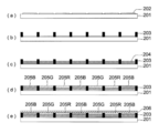
- FIG. 1 is a schematic view showing an example of a display device composed of organic EL elements. It is a schematic diagram of a display such as a mobile phone that displays image information by light emission of an organic EL element.
- the display 1 includes a display unit A having a plurality of pixels, a control unit B that performs image scanning of the display unit A based on image information, and the like.
- the control unit B is electrically connected to the display unit A, and sends a scanning signal and an image data signal to each of a plurality of pixels based on image information from the outside, and the pixels for each scanning line respond to the image data signal by the scanning signal.
- the image information is sequentially emitted to scan the image and display the image information on the display unit A.
- FIG. 2 is a schematic diagram of the display unit A.
- the display unit A has a wiring unit including a plurality of scanning lines 5 and data lines 6 and a plurality of pixels 3 on the substrate.
- the main members of the display unit A will be described below.
- the light emitted from the pixel 3 is extracted in the direction of the white arrow (downward).
- the scanning line 5 and the plurality of data lines 6 in the wiring portion are each made of a conductive material, and the scanning lines 5 and the data lines 6 are orthogonal to each other in a grid pattern and are connected to the pixels 3 at the orthogonal positions (details are illustrated). Not)
- the pixel 3 When the scanning signal is applied from the scanning line 5, the pixel 3 receives the image data signal from the data line 6 and emits light according to the received image data.
- a full color display can be achieved by appropriately arranging pixels in the red region, the green region, and the blue region on the same substrate.
- the lighting device of the present invention will be described.
- the illuminating device of this invention has the said organic EL element.
- the organic EL element of the present invention may be used as an organic EL element having a resonator structure.
- the purpose of use of the organic EL element having such a resonator structure is as follows.
- the light source of a machine, the light source of an optical communication processing machine, the light source of a photosensor, etc. are mentioned, However It is not limited to these. Moreover, you may use for the said use by making a laser oscillation.
- the organic EL element of the present invention may be used as a kind of lamp for illumination or exposure light source, a projection device for projecting an image, or a display for directly viewing a still image or a moving image. It may be used as a device (display).
- the drive method when used as a display device for moving image reproduction may be either a simple matrix (passive matrix) method or an active matrix method.
- a full color display device can be produced by using two or more organic EL elements of the present invention having different emission colors.
- the organic EL material of the present invention can be applied to an organic EL element that emits substantially white light as a lighting device.
- a plurality of light emitting colors are simultaneously emitted by a plurality of light emitting materials to obtain white light emission by color mixing.
- the combination of a plurality of emission colors may include three emission maximum wavelengths of three primary colors of blue, green, and blue, or two using the relationship of complementary colors such as blue and yellow, blue green and orange, etc. The thing containing the light emission maximum wavelength may be used.
- a combination of light emitting materials for obtaining a plurality of emission colors is a combination of a plurality of phosphorescent or fluorescent materials, a light emitting material that emits fluorescence or phosphorescence, and light from the light emitting material as excitation light. Any of those combined with a dye material that emits light may be used, but in the white organic EL device according to the present invention, only a combination of a plurality of light-emitting dopants may be mixed.
- an electrode film can be formed by a vapor deposition method, a cast method, a spin coating method, an ink jet method, a printing method, or the like, and productivity is also improved.
- the elements themselves are luminescent white.
- luminescent material used for a light emitting layer For example, if it is a backlight in a liquid crystal display element, the metal complex which concerns on this invention so that it may suit the wavelength range corresponding to CF (color filter) characteristic, Any one of known luminescent materials may be selected and combined to whiten.
- CF color filter
- the non-light emitting surface of the organic EL device of the present invention is covered with a glass case, a glass substrate having a thickness of 300 ⁇ m is used as a sealing substrate, and an epoxy-based photocurable adhesive (LUX TRACK manufactured by Toagosei Co., Ltd.) is used as a sealing material.
- LC0629B is applied, and this is overlaid on the cathode to be in close contact with the transparent support substrate, irradiated with UV light from the glass substrate side, cured and sealed, and as shown in FIG. 3 and FIG. Can be formed.
- FIG. 3 shows a schematic view of the lighting device, and the organic EL element 101 of the present invention is covered with a glass cover 102 (in the sealing operation with the glass cover, the organic EL element 101 is brought into contact with the atmosphere. And a glove box under a nitrogen atmosphere (in an atmosphere of high-purity nitrogen gas having a purity of 99.999% or more).
- FIG. 4 shows a cross-sectional view of the lighting device.
- 105 denotes a cathode
- 106 denotes an organic EL layer
- 107 denotes a glass substrate with a transparent electrode.
- the glass cover 102 is filled with nitrogen gas 108 and a water catching agent 109 is provided.
- Example 1 Production of Organic EL Element 1-1 >> This ITO transparent electrode was provided after patterning was performed on a substrate (NA-45 manufactured by NH Techno Glass Co., Ltd.) formed by depositing 100 nm of ITO (indium tin oxide) on a 100 mm ⁇ 100 mm ⁇ 1.1 mm glass substrate as an anode.
- the transparent support substrate was ultrasonically cleaned with isopropyl alcohol, dried with dry nitrogen gas, and subjected to UV ozone cleaning for 5 minutes.
- This substrate was transferred to a nitrogen atmosphere, and on the hole transport layer, a solution of 3 mg of the hole transport material 1 and 40 mg of the hole transport material 2 dissolved in 10 ml of toluene was added at 1500 rpm for 30 seconds. A thin film was formed by spin coating on the transport layer. Further, ultraviolet light was irradiated for 180 seconds to carry out photopolymerization and crosslinking, thereby forming a second hole transport layer having a thickness of about 20 nm. On this second hole transport layer, a thin film was formed by spin coating using a solution of 100 mg Host-14 and 10 mg d-2 dissolved in 10 ml toluene at 600 rpm for 30 seconds. It vacuum-dried at 60 degreeC for 1 hour, and was set as the light emitting layer with a film thickness of about 70 nm.
- a thin film was formed on the light emitting layer by spin coating using a solution obtained by dissolving 50 mg of ET-40 in 10 ml of hexafluoroisopropanol (HFIP) at 1000 rpm for 30 seconds. Furthermore, it vacuum-dried at 60 degreeC for 1 hour, and was set as the electron carrying layer with a film thickness of about 30 nm.
- HFIP hexafluoroisopropanol
- this substrate was fixed to a substrate holder of a vacuum evaporation apparatus, and after the vacuum chamber was depressurized to 4 ⁇ 10 ⁇ 4 Pa, lithium fluoride was deposited to 0.4 nm and aluminum was further deposited to 110 nm as a cathode buffer layer. A cathode was formed, and an organic EL element 1-1 was produced.
- Organic EL devices 1-2 to 1-5 were prepared in the same manner as in the production of organic EL device 1-1 except that Host-14, d-2 and ET-40 were changed to the compounds shown in Table 1. .
- CS-1000 manufactured by Konica Minolta Sensing
- the external extraction quantum efficiency was expressed as a relative value where the organic EL element 2-1 was 100.
- the organic EL device continuously emitted light at room temperature under a constant current condition of 2.5 mA / cm 2 , and the time ( ⁇ 1 / 2) required to obtain half the initial luminance was measured.
- the light emission lifetime is expressed as a relative value where the organic EL element 6-1 is set to 100.
- the organic EL device of the present invention has all the characteristics of the external extraction quantum efficiency, the light emission lifetime, and the voltage increase rate as compared with the comparative device.
- Example 2 Preparation of organic EL element 2-1 >> This ITO transparent electrode was provided after patterning was performed on a substrate (NA-45 manufactured by NH Techno Glass Co., Ltd.) formed by depositing 100 nm of ITO (indium tin oxide) on a 100 mm ⁇ 100 mm ⁇ 1.1 mm glass substrate as an anode.
- the transparent support substrate was ultrasonically cleaned with isopropyl alcohol, dried with dry nitrogen gas, and subjected to UV ozone cleaning for 5 minutes.
- the substrate was transferred to a nitrogen atmosphere, and a solution prepared by dissolving 50 mg of the hole transport material 2 in 10 ml of toluene was spin-coated on the hole transport layer at 1500 rpm for 30 seconds on the hole transport layer. Formed. Further, ultraviolet light was irradiated for 180 seconds to carry out photopolymerization and crosslinking, thereby forming a second hole transport layer having a thickness of about 20 nm.
- a thin film was formed by a spin coating method at 200 rpm for 30 seconds using a solution in which 100 mg of Host-25 and 13 mg of comparative dopant 2 were dissolved in 10 ml of toluene. It vacuum-dried at 60 degreeC for 1 hour, and was set as the light emitting layer with a film thickness of about 35 nm.
- a thin film was formed on this light emitting layer by spin coating using a solution of 50 mg of ET-10 dissolved in 10 ml of hexafluoroisopropanol (HFIP) at 2000 rpm for 30 seconds. Furthermore, it vacuum-dried at 60 degreeC for 1 hour, and was set as the electron carrying layer with a film thickness of about 20 nm.
- HFIP hexafluoroisopropanol
- this substrate was fixed to a substrate holder of a vacuum deposition apparatus, the vacuum chamber was depressurized to 4 ⁇ 10 ⁇ 4 Pa, potassium fluoride was deposited at 0.4 nm as a cathode buffer layer, and aluminum was deposited at 110 nm as a cathode.
- a cathode was formed to produce an organic EL element 2-1.
- the organic EL element of the present invention can provide a thick element that can be driven at a low voltage.
- Example 3 Preparation of organic EL element 3-1 >> This ITO transparent electrode was provided after patterning was performed on a substrate (NA-45 manufactured by NH Techno Glass Co., Ltd.) formed by depositing 100 nm of ITO (indium tin oxide) on a 100 mm ⁇ 100 mm ⁇ 1.1 mm glass substrate as an anode.
- the transparent support substrate was ultrasonically cleaned with isopropyl alcohol, dried with dry nitrogen gas, and subjected to UV ozone cleaning for 5 minutes.
- a thin film was formed on this light emitting layer by spin coating using a solution of 50 mg of ET-13 dissolved in 10 ml of hexafluoroisopropanol (HFIP) at 1500 rpm for 30 seconds. Furthermore, it vacuum-dried at 60 degreeC for 1 hour, and was set as the electron carrying layer about 20 nm thick.
- HFIP hexafluoroisopropanol
- this substrate was fixed to a substrate holder of a vacuum deposition apparatus, the vacuum chamber was depressurized to 4 ⁇ 10 ⁇ 4 Pa, lithium fluoride 0.4 nm was deposited as a cathode buffer layer, and aluminum was deposited 110 nm as a cathode.
- a cathode was formed to produce an organic EL element 3-1.
- Organic EL elements 3-2 to 3-5 were prepared in the same manner as in the production of the organic EL element 2-1, except that the host 36 and the comparative dopant 4 were changed to the compounds shown in Table 3.
- the light emission lifetime was evaluated by the same method as in Example 1.
- the light emission lifetime of the organic EL element 3-1 was expressed as a relative value set to 100.
- the emission luminance when a constant current of 2.5 mA / cm 2 was applied at room temperature in a dry nitrogen gas atmosphere was measured using a spectral radiance meter CS-1000 (manufactured by Konica Minolta Sensing).
- the organic EL device of the present invention is superior in all the characteristics of power efficiency, light emission lifetime, and light emission unevenness as compared with the comparative device.
- FIG. 5 shows a schematic configuration diagram of an organic EL full-color display device. After patterning at a pitch of 100 ⁇ m on a substrate (NH45 manufactured by NH Techno Glass Co., Ltd.) having a 100 nm ITO transparent electrode (202) film formed on a glass substrate 201 as an anode, non-between the ITO transparent electrodes on this glass substrate. A photosensitive polyimide partition 203 (width 20 ⁇ m, thickness 2.0 ⁇ m) was formed by photolithography.
- a hole injection layer composition having the following composition is ejected and injected between polyimide partition walls on the ITO electrode using an inkjet head (manufactured by Epson Corporation; MJ800C), irradiated with ultraviolet light for 200 seconds, and dried at 60 ° C. for 10 minutes.
- a hole injection layer 204 having a thickness of 40 nm was produced by the treatment.
- the following blue light-emitting layer composition, green light-emitting layer composition, and red light-emitting layer composition are similarly discharged and injected onto the hole injection layer using an inkjet head and dried at 60 ° C. for 10 minutes.
- Each light emitting layer (205B, 205G, 205R) was formed.
- the produced organic EL element showed blue, green and red light emission by applying a voltage to each electrode, and could be used as a full color display device.
- the substrate was transferred to a nitrogen atmosphere, and a solution of 50 mg of commercially available ADS254BE (American Dye Source, Inc.) dissolved in 10 ml of toluene was spin-coated on the hole transport layer at 2500 rpm for 30 seconds, and a thin film was formed. Formed. It vacuum-dried at 60 degreeC for 1 hour, and formed the 2nd positive hole transport layer.
- ADS254BE American Dye Source, Inc.
- a film was formed by spin coating at 2000 rpm for 30 seconds, followed by vacuum drying at 60 ° C. for 1 hour. It was set as the electron carrying layer.
- this substrate was fixed to a substrate holder of a vacuum vapor deposition apparatus, 200 mg of ET-7 was put into a molybdenum resistance heating boat, and was attached to the vacuum vapor deposition apparatus.
- the energized heating boat containing ET-7 was energized and heated, and deposited on the electron transport layer at a deposition rate of 0.1 nm / second.
- a second electron transport layer having a thickness of 20 nm was provided.
- the substrate temperature at the time of vapor deposition was room temperature.
Landscapes
- Chemical & Material Sciences (AREA)
- Organic Chemistry (AREA)
- Engineering & Computer Science (AREA)
- Materials Engineering (AREA)
- Crystallography & Structural Chemistry (AREA)
- Inorganic Chemistry (AREA)
- Manufacturing & Machinery (AREA)
- Electroluminescent Light Sources (AREA)
Abstract
L'invention concerne : un matériau pour éléments EL organiques capable d'émettre une lumière de courte longueur d'onde, présentant un haut rendement lumineux et une longue durée de vie en émission lumineuse, et adapté à un procédé humide ; ainsi qu'un élément EL organique, un dispositif d'éclairage et un dispositif d'affichage, produits en utilisant le matériau pour éléments EL organiques.
Plus précisément, l'invention concerne un élément EL organique comportant une anode, une cathode et une couche composée organique multicouche contenant une couche luminescente et intercalée entre l'anode et la cathode. L'élément EL organique est caractérisé en ce qu'au moins une couche de la couche composée organique contient un complexe métallique représenté par la formule générale (1).
Priority Applications (1)
| Application Number | Priority Date | Filing Date | Title |
|---|---|---|---|
| JP2011538273A JP5569531B2 (ja) | 2009-10-26 | 2010-04-06 | 有機エレクトロルミネッセンス素子、有機エレクトロルミネッセンス素子材料、表示装置及び照明装置 |
Applications Claiming Priority (2)
| Application Number | Priority Date | Filing Date | Title |
|---|---|---|---|
| JP2009245225 | 2009-10-26 | ||
| JP2009-245225 | 2009-10-26 |
Publications (1)
| Publication Number | Publication Date |
|---|---|
| WO2011052250A1 true WO2011052250A1 (fr) | 2011-05-05 |
Family
ID=43921681
Family Applications (1)
| Application Number | Title | Priority Date | Filing Date |
|---|---|---|---|
| PCT/JP2010/056208 Ceased WO2011052250A1 (fr) | 2009-10-26 | 2010-04-06 | Élément électroluminescent organique, matériau pour éléments électroluminescents organiques, dispositif d'affichage et dispositif d'éclairage |
Country Status (2)
| Country | Link |
|---|---|
| JP (1) | JP5569531B2 (fr) |
| WO (1) | WO2011052250A1 (fr) |
Cited By (10)
| Publication number | Priority date | Publication date | Assignee | Title |
|---|---|---|---|---|
| WO2013042460A1 (fr) * | 2011-09-20 | 2013-03-28 | コニカミノルタホールディングス株式会社 | Élément électroluminescent organique, dispositif d'éclairage et dispositif d'affichage |
| JP2013149812A (ja) * | 2012-01-20 | 2013-08-01 | Konica Minolta Inc | 有機エレクトロルミネッセンス素子、照明装置及び表示装置 |
| JP2013183036A (ja) * | 2012-03-02 | 2013-09-12 | Konica Minolta Inc | 有機エレクトロルミネッセンス素子、表示装置および照明装置 |
| US8642782B2 (en) | 2010-09-21 | 2014-02-04 | Semiconductor Energy Laboratory Co., Ltd. | Carbazole derivative, light-emitting element material and organic semiconductor material |
| US8673459B2 (en) | 2010-09-10 | 2014-03-18 | Semiconductor Energy Laboratory Co., Ltd. | Light-emitting element and electronic device |
| US8697885B2 (en) | 2010-11-30 | 2014-04-15 | Semiconductor Energy Laboratory Co., Ltd. | Carbazole compound, light-emitting element material, organic semiconductor material, light-emitting element, light emitting device, lighting device, and electronic device |
| JP2015508438A (ja) * | 2011-12-28 | 2015-03-19 | ソルヴェイ(ソシエテ アノニム) | ヘテロレプチック発光錯体 |
| JP2017216454A (ja) * | 2017-06-15 | 2017-12-07 | コニカミノルタ株式会社 | 有機エレクトロルミネッセンス素子、照明装置及び表示装置 |
| CN111320614A (zh) * | 2018-12-14 | 2020-06-23 | 乐金显示有限公司 | 具有优异的耐热性和发光性的有机化合物、具有该化合物的有机发光二极管和有机发光装置 |
| CN113166120A (zh) * | 2018-12-10 | 2021-07-23 | 株式会社Lg化学 | 化合物及包含其的有机发光器件 |
Citations (3)
| Publication number | Priority date | Publication date | Assignee | Title |
|---|---|---|---|---|
| JP2005068110A (ja) * | 2003-08-27 | 2005-03-17 | Mitsubishi Chemicals Corp | 有機金属錯体、発光材料、および有機電界発光素子 |
| WO2007097153A1 (fr) * | 2006-02-20 | 2007-08-30 | Konica Minolta Holdings, Inc. | Substance d'élément électroluminescent organique, élément électroluminescent organique, dispositif d'affichage et dispositif d'éclairage |
| JP2008542203A (ja) * | 2005-05-06 | 2008-11-27 | ユニバーサル ディスプレイ コーポレイション | 安定oled材料及び改善された安定性を有するデバイス |
-
2010
- 2010-04-06 WO PCT/JP2010/056208 patent/WO2011052250A1/fr not_active Ceased
- 2010-04-06 JP JP2011538273A patent/JP5569531B2/ja active Active
Patent Citations (3)
| Publication number | Priority date | Publication date | Assignee | Title |
|---|---|---|---|---|
| JP2005068110A (ja) * | 2003-08-27 | 2005-03-17 | Mitsubishi Chemicals Corp | 有機金属錯体、発光材料、および有機電界発光素子 |
| JP2008542203A (ja) * | 2005-05-06 | 2008-11-27 | ユニバーサル ディスプレイ コーポレイション | 安定oled材料及び改善された安定性を有するデバイス |
| WO2007097153A1 (fr) * | 2006-02-20 | 2007-08-30 | Konica Minolta Holdings, Inc. | Substance d'élément électroluminescent organique, élément électroluminescent organique, dispositif d'affichage et dispositif d'éclairage |
Cited By (17)
| Publication number | Priority date | Publication date | Assignee | Title |
|---|---|---|---|---|
| US8673459B2 (en) | 2010-09-10 | 2014-03-18 | Semiconductor Energy Laboratory Co., Ltd. | Light-emitting element and electronic device |
| US10833282B2 (en) | 2010-09-10 | 2020-11-10 | Semiconductor Energy Laboratory Co., Ltd. | Light-emitting element and electronic device |
| US9735372B2 (en) | 2010-09-10 | 2017-08-15 | Semiconductor Energy Laboratory Co., Ltd. | Light-emitting element and electronic device |
| US9065058B2 (en) | 2010-09-10 | 2015-06-23 | Semiconductor Energy Laboratory Co., Ltd. | Light-emitting element and electronic device |
| US9450188B2 (en) | 2010-09-21 | 2016-09-20 | Semiconductor Energy Laboratory Co., Ltd. | Carbazole derivative, light-emitting element material and organic semiconductor material |
| US8642782B2 (en) | 2010-09-21 | 2014-02-04 | Semiconductor Energy Laboratory Co., Ltd. | Carbazole derivative, light-emitting element material and organic semiconductor material |
| US10071993B2 (en) | 2010-09-21 | 2018-09-11 | Semiconductor Energy Laboratory Co., Ltd. | Carbazole derivative, light-emitting element material and organic semiconductor material |
| US8697885B2 (en) | 2010-11-30 | 2014-04-15 | Semiconductor Energy Laboratory Co., Ltd. | Carbazole compound, light-emitting element material, organic semiconductor material, light-emitting element, light emitting device, lighting device, and electronic device |
| WO2013042460A1 (fr) * | 2011-09-20 | 2013-03-28 | コニカミノルタホールディングス株式会社 | Élément électroluminescent organique, dispositif d'éclairage et dispositif d'affichage |
| JP2015508438A (ja) * | 2011-12-28 | 2015-03-19 | ソルヴェイ(ソシエテ アノニム) | ヘテロレプチック発光錯体 |
| JP2013149812A (ja) * | 2012-01-20 | 2013-08-01 | Konica Minolta Inc | 有機エレクトロルミネッセンス素子、照明装置及び表示装置 |
| JP2013183036A (ja) * | 2012-03-02 | 2013-09-12 | Konica Minolta Inc | 有機エレクトロルミネッセンス素子、表示装置および照明装置 |
| JP2017216454A (ja) * | 2017-06-15 | 2017-12-07 | コニカミノルタ株式会社 | 有機エレクトロルミネッセンス素子、照明装置及び表示装置 |
| CN113166120A (zh) * | 2018-12-10 | 2021-07-23 | 株式会社Lg化学 | 化合物及包含其的有机发光器件 |
| CN111320614A (zh) * | 2018-12-14 | 2020-06-23 | 乐金显示有限公司 | 具有优异的耐热性和发光性的有机化合物、具有该化合物的有机发光二极管和有机发光装置 |
| US11683982B2 (en) | 2018-12-14 | 2023-06-20 | Lg Display Co., Ltd. | Organic compound having excellent thermal resistance property and luminescent property, organic light emitting diode and organic light emitting device having the compound |
| CN111320614B (zh) * | 2018-12-14 | 2023-11-03 | 乐金显示有限公司 | 具有优异的耐热性和发光性的有机化合物、具有该化合物的有机发光二极管和有机发光装置 |
Also Published As
| Publication number | Publication date |
|---|---|
| JP5569531B2 (ja) | 2014-08-13 |
| JPWO2011052250A1 (ja) | 2013-03-14 |
Similar Documents
| Publication | Publication Date | Title |
|---|---|---|
| JP5765223B2 (ja) | 有機エレクトロルミネッセンス素子の製造方法、並びに有機エレクトロルミネッセンス素子を備えた照明装置及び表示装置 | |
| JP5482201B2 (ja) | 有機エレクトロルミネッセンス素子、表示装置及び照明装置 | |
| JP5853964B2 (ja) | 有機エレクトロルミネッセンス素子、照明装置及び表示装置 | |
| JP5857754B2 (ja) | 有機エレクトロルミネッセンス素子、有機エレクトロルミネッセンス素子の製造方法、表示装置及び照明装置 | |
| JP5585382B2 (ja) | 有機エレクトロルミネッセンス素子、照明装置及び表示装置 | |
| JP5653617B2 (ja) | 有機エレクトロルミネッセンス素子、有機エレクトロルミネッセンス素子材料、表示装置及び照明装置 | |
| JP5659478B2 (ja) | 有機エレクトロルミネッセンス素子、照明装置及び表示装置 | |
| JP5531446B2 (ja) | 有機エレクトロルミネッセンス素子、有機エレクトロルミネッセンス素子材料、表示装置および照明装置 | |
| JP5577650B2 (ja) | 有機エレクトロルミネッセンス素子、有機エレクトロルミネッセンス素子材料、表示装置及び照明装置 | |
| JP5724204B2 (ja) | 有機エレクトロルミネッセンス素子、表示装置、及び照明装置 | |
| JP5600894B2 (ja) | 白色有機エレクトロルミネッセンス素子、表示装置及び照明装置 | |
| JP5870782B2 (ja) | 有機エレクトロルミネッセンス素子、有機エレクトロルミネッセンス素子の製造方法、照明装置及び表示装置 | |
| JP5900001B2 (ja) | 有機エレクトロルミネッセンス素子、それが具備された表示装置及び照明装置 | |
| JP5652083B2 (ja) | 有機エレクトロルミネッセンス素子、表示装置及び照明装置 | |
| JP5652235B2 (ja) | 有機エレクトロルミネッセンス素子、表示装置及び照明装置 | |
| JP5708176B2 (ja) | 有機エレクトロルミネッセンス素子材料、有機エレクトロルミネッセンス素子、表示装置及び照明装置 | |
| JP5569531B2 (ja) | 有機エレクトロルミネッセンス素子、有機エレクトロルミネッセンス素子材料、表示装置及び照明装置 | |
| JP6094480B2 (ja) | 有機エレクトロルミネッセンス素子、照明装置、表示装置及び有機エレクトロルミネッセンス素子の製造方法 | |
| WO2010032663A1 (fr) | Élément électroluminescent organique, dispositif d'affichage, dispositif d'éclairage et matériau d'élément électroluminescent organique | |
| JP5629970B2 (ja) | 有機エレクトロルミネッセンス素子、表示装置及び照明装置 | |
| JP5692011B2 (ja) | 有機エレクトロルミネッセンス素子材料、有機エレクトロルミネッセンス素子、表示装置、並びに照明装置 | |
| JP5463897B2 (ja) | 有機エレクトロルミネッセンス素子、有機エレクトロルミネッセンス素子材料、表示装置及び照明装置 | |
| WO2013027633A1 (fr) | Elément électroluminescent organique, dispositif d'éclairage et dispositif d'affichage | |
| JP5600884B2 (ja) | 有機エレクトロルミネッセンス素子、有機エレクトロルミネッセンス素子材料、表示装置及び照明装置 | |
| JP5320881B2 (ja) | 有機エレクトロルミネッセンス素子、表示装置、照明装置及び有機エレクトロルミネッセンス素子材料 |
Legal Events
| Date | Code | Title | Description |
|---|---|---|---|
| 121 | Ep: the epo has been informed by wipo that ep was designated in this application |
Ref document number: 10826385 Country of ref document: EP Kind code of ref document: A1 |
|
| WWE | Wipo information: entry into national phase |
Ref document number: 2011538273 Country of ref document: JP |
|
| NENP | Non-entry into the national phase |
Ref country code: DE |
|
| 122 | Ep: pct application non-entry in european phase |
Ref document number: 10826385 Country of ref document: EP Kind code of ref document: A1 |