WO2011052348A1 - Procédé de surveillance de la concentration en dialysat et dispositif pour sa mise en oeuvre - Google Patents
Procédé de surveillance de la concentration en dialysat et dispositif pour sa mise en oeuvre Download PDFInfo
- Publication number
- WO2011052348A1 WO2011052348A1 PCT/JP2010/067402 JP2010067402W WO2011052348A1 WO 2011052348 A1 WO2011052348 A1 WO 2011052348A1 JP 2010067402 W JP2010067402 W JP 2010067402W WO 2011052348 A1 WO2011052348 A1 WO 2011052348A1
- Authority
- WO
- WIPO (PCT)
- Prior art keywords
- dialysate
- concentration
- liquid
- electrical conductivity
- change
- Prior art date
- Legal status (The legal status is an assumption and is not a legal conclusion. Google has not performed a legal analysis and makes no representation as to the accuracy of the status listed.)
- Ceased
Links
Images


Classifications
-
- A—HUMAN NECESSITIES
- A61—MEDICAL OR VETERINARY SCIENCE; HYGIENE
- A61M—DEVICES FOR INTRODUCING MEDIA INTO, OR ONTO, THE BODY; DEVICES FOR TRANSDUCING BODY MEDIA OR FOR TAKING MEDIA FROM THE BODY; DEVICES FOR PRODUCING OR ENDING SLEEP OR STUPOR
- A61M1/00—Suction or pumping devices for medical purposes; Devices for carrying-off, for treatment of, or for carrying-over, body-liquids; Drainage systems
- A61M1/14—Dialysis systems; Artificial kidneys; Blood oxygenators ; Reciprocating systems for treatment of body fluids, e.g. single needle systems for hemofiltration or pheresis
- A61M1/16—Dialysis systems; Artificial kidneys; Blood oxygenators ; Reciprocating systems for treatment of body fluids, e.g. single needle systems for hemofiltration or pheresis with membranes
- A61M1/1654—Dialysates therefor
- A61M1/1656—Apparatus for preparing dialysates
-
- A—HUMAN NECESSITIES
- A61—MEDICAL OR VETERINARY SCIENCE; HYGIENE
- A61M—DEVICES FOR INTRODUCING MEDIA INTO, OR ONTO, THE BODY; DEVICES FOR TRANSDUCING BODY MEDIA OR FOR TAKING MEDIA FROM THE BODY; DEVICES FOR PRODUCING OR ENDING SLEEP OR STUPOR
- A61M1/00—Suction or pumping devices for medical purposes; Devices for carrying-off, for treatment of, or for carrying-over, body-liquids; Drainage systems
- A61M1/14—Dialysis systems; Artificial kidneys; Blood oxygenators ; Reciprocating systems for treatment of body fluids, e.g. single needle systems for hemofiltration or pheresis
- A61M1/16—Dialysis systems; Artificial kidneys; Blood oxygenators ; Reciprocating systems for treatment of body fluids, e.g. single needle systems for hemofiltration or pheresis with membranes
- A61M1/1601—Control or regulation
- A61M1/1603—Regulation parameters
- A61M1/1605—Physical characteristics of the dialysate fluid
-
- A—HUMAN NECESSITIES
- A61—MEDICAL OR VETERINARY SCIENCE; HYGIENE
- A61M—DEVICES FOR INTRODUCING MEDIA INTO, OR ONTO, THE BODY; DEVICES FOR TRANSDUCING BODY MEDIA OR FOR TAKING MEDIA FROM THE BODY; DEVICES FOR PRODUCING OR ENDING SLEEP OR STUPOR
- A61M1/00—Suction or pumping devices for medical purposes; Devices for carrying-off, for treatment of, or for carrying-over, body-liquids; Drainage systems
- A61M1/14—Dialysis systems; Artificial kidneys; Blood oxygenators ; Reciprocating systems for treatment of body fluids, e.g. single needle systems for hemofiltration or pheresis
- A61M1/16—Dialysis systems; Artificial kidneys; Blood oxygenators ; Reciprocating systems for treatment of body fluids, e.g. single needle systems for hemofiltration or pheresis with membranes
- A61M1/1621—Constructional aspects thereof
- A61M1/1635—Constructional aspects thereof with volume chamber balancing devices between used and fresh dialysis fluid
- A61M1/1639—Constructional aspects thereof with volume chamber balancing devices between used and fresh dialysis fluid linked by membranes
-
- G—PHYSICS
- G01—MEASURING; TESTING
- G01N—INVESTIGATING OR ANALYSING MATERIALS BY DETERMINING THEIR CHEMICAL OR PHYSICAL PROPERTIES
- G01N27/00—Investigating or analysing materials by the use of electric, electrochemical, or magnetic means
- G01N27/02—Investigating or analysing materials by the use of electric, electrochemical, or magnetic means by investigating impedance
- G01N27/04—Investigating or analysing materials by the use of electric, electrochemical, or magnetic means by investigating impedance by investigating resistance
- G01N27/06—Investigating or analysing materials by the use of electric, electrochemical, or magnetic means by investigating impedance by investigating resistance of a liquid
- G01N27/08—Investigating or analysing materials by the use of electric, electrochemical, or magnetic means by investigating impedance by investigating resistance of a liquid which is flowing continuously
- G01N27/10—Investigation or analysis specially adapted for controlling or monitoring operations or for signalling
Definitions
- the present invention relates to a dialysate concentration monitoring method and apparatus, and more particularly, to measure the electrical conductivity of a dialysate and monitor the dialysate concentration while comparing the electrical conductivity with a predetermined reference value.
- the present invention relates to a concentration monitoring method and apparatus therefor.
- a liquid, B liquid and dilution water are mixed to prepare a dialysate, and the prepared dialysate is supplied to the dialyzer. Monitoring is always performed, and when the concentration falls outside the predetermined concentration, the supply is stopped and an alarm is output.
- a dialysate concentration monitoring method a method for measuring the dialysate concentration by electric conductivity is known.
- a dialyser is provided with a means for measuring electric conductivity, and a dialysate prepared in advance is used. By setting a reference value for the electrical conductivity, and comparing the value measured by the measuring means with the reference value, it is monitored whether or not the dialysate has a predetermined concentration (Patent Literature).
- the concentration of each component contained in the A solution and the B solution is input, and the reference value of the electrical conductivity of the dialysate to be created is calculated from the concentration of these components and the mixing ratio.
- the said A liquid dissolves A agent mainly consisting of electrolyte and butter sugar in water
- B liquid dissolves B agent which has sodium hydrogen carbonate as a main component in water.
- RO water purified through a reverse osmosis membrane is used.
- the reference value of the electrical conductivity must be changed at the same time when changing the concentration of the dialysate to be created.
- the operator of the dialyzer has to respond to the correspondence between the dialysate concentration and the electrical conductivity.
- the reference value was reset by referring to the table.
- the electrical conductivity of the dialysate is different if the mixing ratio of the liquid A and the liquid B is different even when the concentrations are the same as the dialysate. It took a lot of labor to measure the above-mentioned values, and resetting of the reference values could not be performed during dialysis treatment.
- Patent Document 1 it is possible to calculate a new reference value by changing the mixing ratio.
- each component concentration that is a basis for calculating the reference value is not an actual measurement value but a nominal value. Therefore, the calculated reference value may differ from the actually measured value of the electrical conductivity of the dialysate prepared.
- the present invention makes it easy to set a reference value of electrical conductivity according to the concentration of the dialysate to be created, and a dialysate concentration monitoring method that can cope with concentration changes during dialysis treatment and The apparatus is provided.
- the dialysate concentration monitoring method measures the electrical conductivity of a dialysate prepared by mixing A liquid, B liquid and dilution water, and determines the electrical conductivity in advance.
- the dialysate concentration monitoring method for monitoring the concentration compared to the reference value Obtain the ratio of the change in the electrical conductivity of the dialysate with respect to the change in the concentration of the liquid A alone and the ratio of the change in the electrical conductivity of the dialysate with respect to the change in the concentration of the liquid B alone.
- the electrical conductivity of the dialysate prepared based on the ratio of the change in the electrical conductivity of the dialysate with respect to the change in the concentration of the A solution and the B solution, corresponding to the concentration of the A solution and the B solution. Seeking The reference value is set from the electrical conductivity.
- the dialysate concentration monitoring device is provided in a dialyzer for preparing a dialysate by mixing A solution, B solution and dilution water according to a set mixing ratio
- a dialysate concentration monitoring device comprising a conductivity measuring means for measuring the electrical conductivity of a dialysate and monitoring the concentration by comparing the measured electrical conductivity with a predetermined reference value, Concentration adjusting means for adjusting the mixing amount of the A liquid, B liquid and dilution water of the dialysate, and setting changing means for changing the setting of the reference value
- the concentration adjusting means changes only the concentration of dialysate A and only the concentration of liquid B
- the conductivity measuring means measures the electrical conductivity of these multiple dialysates
- the setting change means obtains a rate of change in the electrical conductivity of the dialysate with respect to a change in the concentration of only the A liquid and a rate of change in the electrical conductivity of the dialysate with respect to a change in the concentration of only the concentration of only the
- the electrical conductivity of the newly prepared dialysate is determined, and the reference value is calculated from the electrical conductivity. It is characterized by setting.
- the rate of change in the electrical conductivity of the dialysate with respect to the change in the concentration of only the liquid A, and the rate of change in the electrical conductivity of the dialysate with respect to the change in the concentration of only the B solution It is possible to obtain the electrical conductivity of the dialysate to be created.
- the reference value of the electrical conductivity according to the concentration of the dialysate to be created can be easily set, and the concentration change during dialysis treatment can be dealt with.
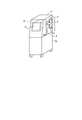
- the perspective view of the dialysis apparatus concerning a present Example The liquid circuit diagram of the dialysis apparatus concerning a present Example.
- FIG. 1 shows an overall view of a dialysis machine 1 and FIG. 2 shows a liquid circuit provided inside the dialysis machine 1.
- the dialysis machine 1 is a dialysate for one patient. This is a personal dialysis machine that performs dialysis treatment.
- the dialyzer 1 constitutes a dialyzer 2 held in the main body 1a, a blood circuit 3 connected to the dialyzer 2, a dialysate circuit 4 provided in the main body 1a, and a concentration monitoring device.
- the control means 1b to perform is provided.
- the control means 1b is provided with a touch panel type input unit 1c that can perform a required operation. The operator sets the concentration of the dialysate used during dialysis treatment by operating the input unit 1c. It has become.
- a hollow fiber (not shown) is provided inside the dialyzer 2.
- the hollow fiber communicates with the blood circuit 3 to allow blood to flow.
- the hollow fiber communicates with the dialysate circuit 4.
- the dialysate flows in the opposite direction to the blood.
- a dialysate circuit 4 shown in FIG. 2 includes a water supply means (not shown) for supplying purified water such as RO water as dilution water, an A solution container 5 for supplying solution A as a dialysate concentrate, and a dialysate concentrate.
- the B liquid container 6 for supplying the B liquid is connected to a drain pipe (not shown) through which the used dialysate is discharged.
- the purified water supplied from the water supply means in the dialysate circuit 4 the A liquid supplied from the A liquid container 5, and the B liquid supplied from the B liquid container 6 are mixed and dialyzed.
- Dialysis treatment is performed by preparing a liquid and supplying the dialysate to the dialyzer 2.
- the dialysate circuit 4 includes two first and second chambers 11 and 12, a water supply passage 13 connected to the first and second chambers 11 and 12 through which purified water from the water supply means flows, and the water supply A liquid supply passage 14 connected to the passage 13 through which the A liquid in the A liquid container 5 flows; B liquid supply passage 15 connected to the water supply passage 13 through which the B liquid in the B liquid container 6 flows; An unused dialysate passage 16 which is provided between the first and second chambers 11 and 12 and the dialyzer 2 and through which unused dialysate flows, the first and second chambers 11 and 12 and the dialyzer 2 A used dialysate passage 17 through which the used dialysate flows and a drainage passage 18 for discharging the used dialysate from the first and second chambers 11 and 12 to the drainage pipe; It has.
- the first and second chambers 11 and 12 have the same shape, and the interior thereof is divided into two chambers by diaphragms 11a and 12a, and the water supply passage 13 and the unused dialysate passage are provided in one space on the right side in the figure. 16 is connected, and the used dialysate passage 17 and the drainage passage 18 are connected to the other space on the left side of the figure.
- the water supply passage 13 is provided with a water purification pump P1 that adjusts the supply amount of purified water under the control of the control means 1b, and the downstream portion of the water supply passage 13 branches in two directions, and the first and second chambers 11 respectively. , 12 and solenoid valves V1, V2 are provided at the branch portions, respectively.
- the A liquid supply passage 14 is connected to the upstream side of the branch portion in the water supply passage 13 and includes an A liquid pump P2.
- the A liquid pump P2 controls the supply amount of the A liquid under the control of the control means 1b. It is possible to adjust.
- the B liquid supply passage 15 is connected upstream of the connection position of the A liquid supply passage 14 in the water supply passage 13 and includes a B liquid pump P3.
- the B liquid pump P3 is controlled by the control means 1b. It is possible to adjust the supply amount of the B liquid.
- the water purification pump P1, the A liquid pump P2, and the B liquid pump P3 constitute a concentration adjusting means that is provided in the concentration monitoring device and adjusts the mixing amount of the A liquid, the B liquid, and the dilution water.
- the unused dialysate passage 16 has its upstream portion branched in two directions and connected to the first and second chambers 11 and 12, respectively, and electromagnetic valves V3 and V4 are provided at the branched portions, respectively. .
- the unused dialysate passage 16 has a conductivity sensor S as a conductivity measuring means for measuring the electrical conductivity of the dialysate prepared in the first and second chambers 11 and 12, and is not used downstream thereof. And an electromagnetic valve V5 for closing the dialysate passage 16.
- the used dialysate passage 17 has a downstream portion branched in two directions and connected to the first and second chambers 11 and 12, respectively, and solenoid valves V6 and V7 are provided at the branched portions, respectively. .
- the used dialysate passage 17 is provided with a dialysate pump P4 for feeding the dialysate in the dialyzer 2, and this dialysate pump P4 is dialyzed through the dialyzer 2 under the control of the control means 1b. The flow rate of the liquid is adjusted. Further, a defective dialysate discharge passage 19 is arranged between the conductivity sensor S and the solenoid valve V5 in the unused dialysate passage 16 and between the upstream side of the dialysate pump P4 in the used dialysate passage 17. The defective dialysate discharge passage 19 is provided with a solenoid valve V8.
- the drainage passage 18 has an upstream portion branched in two directions and connected to the first and second chambers 11 and 12, respectively, and electromagnetic valves V9 and V10 are provided at the branch portions, respectively.
- a water removal passage 20 is provided between the used dialysis passage 17 and the drainage passage 18, and a water removal pump P5 is provided in the water removal passage 20, and the above-mentioned during the dialysis treatment. By operating the water removal pump P ⁇ b> 5, a water removal equivalent amount is directly discharged into the liquid discharge passage 18.
- the electromagnetic valve V1 on the first chamber 11 side in the water supply passage 13 is opened, the electromagnetic valve V2 on the second chamber 12 side is closed, and the unused dialysate passage 16 is provided.
- the electromagnetic valve V6 on the first chamber 11 side in the used dialysate passage 17 is closed.
- the electromagnetic valve V7 on the second chamber 12 side is opened, the electromagnetic valve V9 on the first chamber 11 side in the drainage passage 18 is opened, and the electromagnetic valve V10 on the second chamber 12 side is closed. It has become.
- the purified water pump P1 sends purified water supplied from the water supply means in a predetermined supply amount
- the A solution pump P2 sends A solution from the A solution container 5 in a specified supply amount
- the B liquid pump P3 feeds the B liquid from the B liquid container 6 at a predetermined supply amount.
- the purified water, the A liquid, and the B liquid flow into one space of the first chamber 11 at a predetermined ratio, and are mixed to create an unused dialysate having a preset concentration.
- the used dialysate has already been stored in the other space of the first chamber 11, and the purified water, the A liquid, and the B liquid flow into the one space of the first chamber 11.
- the spent dialysate is pushed out into the drainage passage 18 through the diaphragm 11a and discharged into the drainage pipe.
- the dialysate pump P4 feeds the used dialysate in the used dialysate passage 17 at a predetermined flow rate, so that the unused dialysate prepared in one space of the second chamber 12 is unused dialyzed. It is supplied to the dialyzer 2 through the liquid passage 16. At the same time, the spent dialysate flows from the dialyzer 2 into the other space of the second chamber 12.
- the first chamber 11 and the second chamber 12 are alternately dialyzed by switching the open / close states of the solenoid valves V1, V2, V3, V4, V6, V7, V9, and V10. A liquid is prepared and a dialysate is supplied.
- the unused dialysate that has flowed out into the unused dialysate passage 16 is measured for electrical conductivity by a conductivity sensor S as a conductivity measuring means provided in the unused dialysate passage 16 and is used as a concentration monitoring device as control means.
- 1b compares the measured electrical conductivity with a preset reference value to determine whether or not the concentration of the unused dialysate is appropriate.
- the control unit 1b determines that the concentration of this unused dialysate is appropriate.
- the control means 1b determines that the concentration of the unused dialysate is abnormal, outputs an alarm command, and displays an alarm on the input unit 1c. Further, the electromagnetic valve V5 is closed and the electromagnetic valve V8 is opened, so that the unused dialysate is discharged to the defective dialysate discharge passage 19 and the used dialysate passage 17.
- dialysis is performed by supplying the dialysate 2 to the dialyzer 2 while supplying the purified water, the A liquid, and the B liquid to the first chamber 11 and the second chamber 12.
- concentration of the dialysate produced is monitored by measuring its electrical conductivity.
- the conductivity sensor S for measuring the electrical conductivity of the dialysate and the control means 1b for comparing the reference value with the measured electrical conductivity constitute a dialysate concentration monitoring device.
- the concentration of the dialysate to be created can be set according to the individual patient, and the operator can set the A solution concentration in the input unit 1c of the dialyzer 1.
- the concentration monitoring device automatically changes the reference value for monitoring the concentration, and monitors the changed concentration of the dialysate.
- the concentration monitoring apparatus of the present embodiment is provided with setting changing means for changing the setting of the reference value, and the concentration of the dialysate newly created by the setting changing means is adjusted to the concentration of the A liquid and the B liquid.
- the electric conductivity is obtained, and a new reference value is set from here, and the control means 1b monitors the concentration of the dialysate prepared based on this new reference value. Yes.
- FIG. 3 shows a setting screen displayed on the input unit 1c of the dialysis device 1, and this setting operation is performed before dialysis treatment. This is done in advance.
- the sample numbers 1 to 5 in order from the left side, concentration of solution A (mEq / L), concentration of solution B (mEq / L), dialysate solution consisting of these concentrations of solution A and solution B, The electric conductivity (mS / cm) is shown, and below the table, there are provided columns for inputting the A solution concentration and B solution concentration of the dialysate used during dialysis treatment.
- the value of sample number 1 is the basic concentration and the basic electrical conductivity
- the operator inputs the basic concentrations of the liquid A and the liquid B of the sample number 1 from the input unit 1c as the basic electrical conductivity.
- the values of the dialysate used at the start of treatment are input as the concentration of solution A and solution B input as the basic concentrations, but values previously registered in the control means 1b are used. Also good.
- Concentration adjusting means automatically sets the concentration of solution A and the concentration of solution B for sample numbers 2 to 4 with respect to the concentrations of solution A and solution B as the basic concentrations.
- the values of sample numbers 2 and 3 are obtained by making the B solution concentration different from the basic concentration of sample number 1 by a predetermined amount by 10 mEq / L with respect to the basic concentration.
- Sample number 2 has a low B liquid concentration
- sample number 3 has a high B liquid concentration.
- the values of sample numbers 4 and 5 are obtained by changing the concentration of solution A by a predetermined amount with respect to the basic concentration of sample number 1, and each sample number 4 is 20 mEq / L with respect to the basic concentration.
- the liquid concentration is high, and Sample No. 5 has a low A liquid concentration.
- the value set by the concentration adjusting means at this time is preferably in a range that includes the A solution concentration and the B solution concentration of the dialysate prepared during dialysis treatment.
- the concentration adjusting means sets the A liquid concentration and the B liquid concentration of sample numbers 2 to 5
- the concentration adjusting means is based on the A liquid concentration and B liquid concentration of sample number 1 prior to treatment.
- the purified water pump P1, the A liquid pump P2, and the B liquid pump P3 are controlled, and the dialysate is prepared in the first and second chambers 11 and 12.
- the dialysate is discharged from the first and second chambers 11 and 12 and flows through the unused dialysate passage 16, and the electrical conductivity is measured by the conductivity sensor S.
- the conductivity is registered in the setting change means as the basic electrical conductivity of sample number 1 and displayed in a table on the screen.
- dialysate was prepared based on the concentrations of solution A and solution B, and the electrical conductivity of each of the prepared dialysate was measured. Register the measured value in and display it in the table on the screen.
- the setting changing means calculates the A liquid concentration from the A liquid concentration value and the measured electrical conductivity value. The rate of change in the electrical conductivity of the dialysate relative to the change in concentration is obtained.
- the setting changing means calculates the B solution from the B solution concentration value and the measured electrical conductivity value. Determine the rate of change in the electrical conductivity of the dialysate relative to the change in concentration.
- the slope of the straight line A obtained from the values of sample numbers 1, 4 and 5 that differ only in the concentration of solution A corresponds to the rate of change in the electrical conductivity of the dialysate relative to the change in concentration of solution A.
- the slope of the straight line B obtained from the values of sample numbers 1, 2, and 3 that differ only in the B liquid concentration corresponds to the ratio of the change in the electrical conductivity of the dialysate with respect to the change in the B liquid concentration.
- the electrical conductivity of the dialysate prepared based on the obtained change rate of electrical conductivity is obtained, and a reference value for concentration monitoring is set from the electrical conductivity. .
- the basic electrical conductivity measured above is set, and the basic electrical conductivity is corrected based on the rate of change, thereby obtaining the electrical conductivity of the dialysate to be created. Yes.
- the slope of the straight line A is 0.1
- the slope of the straight line B is 0.025.
- the basic electrical conductivity is corrected and the electrical conductivity of the dialysate to be created is obtained.
- a dialysis fluid having a basic concentration of 110 mEq / L for liquid A, 30 mEq / L for liquid B, and a basic electrical conductivity of 14.00 mS / cm is newly created.
- the case where the dialysate solution A concentration is 100 mEq / L and the solution B concentration is 20 mEq / L will be described.
- the setting change means obtains the difference between the basic concentration and the newly created concentration for the liquid A.
- the difference in concentration is ⁇ 10 mEq / L.
- the electric power increased or decreased with respect to the basic electric conductivity from the difference in the concentration of the liquid A and the ratio of the change in the electric conductivity of the dialysate with respect to the concentration change of the liquid A alone (slope of the straight line A).
- the conductivity value is, in the case of the above example, when the concentration of solution A changes by -10 mEq / L, the electric conductivity changes by an amount multiplied by 0.1, and therefore changes by -1 mS / cm with respect to the basic electric conductivity. It will be.
- the setting changing means obtains the difference between the basic concentration and the newly created concentration for the B liquid.
- the difference in concentration is ⁇ 10 mEq / L.
- the electric power increased or decreased with respect to the basic electric conductivity from the difference in the B liquid concentration obtained and the rate of change in the electric conductivity of the dialysate with respect to the concentration change of only the B liquid (slope of the straight line B).
- the conductivity value is, in the case of the above example, when the concentration of solution B changes by ⁇ 10 mEq / L, the electric conductivity changes by an amount multiplied by 0.025, and therefore ⁇ 0.25 mS / cm with respect to the basic electric conductivity. Will change.
- the basic electrical conductivity is corrected by using the change amount of the electrical conductivity corresponding to the change in the concentration of the liquid A and the liquid B obtained above, and in this example, the basic electrical conductivity is 14.00 mS.
- a new electric conductivity obtained by subtracting 1.00 mS / cm for liquid A and 0.25 mS / cm for liquid B a value of 12.75 mS / cm is obtained.
- the setting changing means sets a reference value for monitoring the concentration of a newly created dialysate from the obtained electrical conductivity, and registers the reference value in the control means 1b as a concentration monitoring device.
- the control means 1b monitors the dialysate based on this reference value.
- the concentration monitoring device when a predetermined basal concentration is set in the concentration monitoring device, first, the electric conductivity of the dialysate composed of this basal concentration is measured, and this is set as the basal electric conductivity. Yes. Next, the difference between the concentration of solution A as the basic concentration and the concentration of solution A of the newly prepared dialysate is obtained, and based on the rate of change in the electrical conductivity of the dialysate that changes only the concentration of solution A. The value of electrical conductivity that is increased or decreased from the basic electrical conductivity is obtained.
- the difference between the B liquid concentration as the basal concentration and the B liquid concentration of the newly prepared dialysate is obtained, and based on the rate of change in the electrical conductivity of the dialysate with only the B liquid concentration changed, the basic The value of the electrical conductivity that is increased or decreased from the electrical conductivity is obtained. And the said basic electrical conductivity is correct
- the control means 1b obtains the electrical conductivity of the dialysate to be created, and the concentration monitoring The reference value is set automatically. This makes it possible to change the dialysate concentration even during dialysis treatment.
- the electrical conductivity of the dialysate with respect to changes in the concentrations of the A and B solutions Therefore, it is possible to determine the electrical conductivity of the dialysate as accurately as possible.
- Dialysis apparatus 1b Control means 4 Dialysate circuit 5 A liquid container 6 B liquid container 13 Water supply path 14 A liquid supply path 15 B liquid supply path 16 Unused dialysate path S Conductivity sensor
Landscapes
- Health & Medical Sciences (AREA)
- Heart & Thoracic Surgery (AREA)
- Urology & Nephrology (AREA)
- Anesthesiology (AREA)
- Vascular Medicine (AREA)
- Engineering & Computer Science (AREA)
- Emergency Medicine (AREA)
- Biomedical Technology (AREA)
- Hematology (AREA)
- Life Sciences & Earth Sciences (AREA)
- Animal Behavior & Ethology (AREA)
- General Health & Medical Sciences (AREA)
- Public Health (AREA)
- Veterinary Medicine (AREA)
- External Artificial Organs (AREA)
Abstract
Selon la présente invention, la concentration d'un dialysat, qui est préparé par le mélange d'une solution A et d'une solution B avec de l'eau de dilution, est surveillée par la mesure de la conductivité électrique du dialysat et la comparaison de la conductivité électrique avec une norme prédéterminée. Tout d'abord, le rapport de modification de la conductivité électrique du dialysat à la modification de la concentration de la solution A seule (droite A) et le rapport de modification de la conductivité électrique du dialysat à la modification de la concentration de la solution B seule (droite B) sont déterminés. Ensuite, la conductivité électrique du dialysat à préparer est déterminée sur la base des rapports de modification de la conductivité électrique du dialysat à la modification de la concentration de la solution A et à la modification de la concentration de la solution B tels que décrits ci-dessus, par rapport à la concentration de la solution A et à la concentration de la solution B dans le dialysat à préparer. Ensuite, la norme susdite est fixée à partir de la conductivité électrique ainsi déterminée. Ainsi, la conductivité électrique peut être facilement fixée en fonction de la concentration du dialysat et une modification de concentration pendant un traitement de dialyse peut être gérée.
Priority Applications (2)
| Application Number | Priority Date | Filing Date | Title |
|---|---|---|---|
| EP10826482.1A EP2494998B1 (fr) | 2009-10-29 | 2010-10-05 | Procédé de surveillance de la concentration en dialysat et dispositif pour sa mise en oeuvre |
| CN201080035949.5A CN102510760B (zh) | 2009-10-29 | 2010-10-05 | 透析液的浓度监视装置的工作方法及其装置 |
Applications Claiming Priority (2)
| Application Number | Priority Date | Filing Date | Title |
|---|---|---|---|
| JP2009249001A JP5423318B2 (ja) | 2009-10-29 | 2009-10-29 | 透析液の濃度監視装置およびその作動方法 |
| JP2009-249001 | 2009-10-29 |
Publications (1)
| Publication Number | Publication Date |
|---|---|
| WO2011052348A1 true WO2011052348A1 (fr) | 2011-05-05 |
Family
ID=43921775
Family Applications (1)
| Application Number | Title | Priority Date | Filing Date |
|---|---|---|---|
| PCT/JP2010/067402 Ceased WO2011052348A1 (fr) | 2009-10-29 | 2010-10-05 | Procédé de surveillance de la concentration en dialysat et dispositif pour sa mise en oeuvre |
Country Status (4)
| Country | Link |
|---|---|
| EP (1) | EP2494998B1 (fr) |
| JP (1) | JP5423318B2 (fr) |
| CN (1) | CN102510760B (fr) |
| WO (1) | WO2011052348A1 (fr) |
Cited By (5)
| Publication number | Priority date | Publication date | Assignee | Title |
|---|---|---|---|---|
| JP2013150767A (ja) * | 2011-12-29 | 2013-08-08 | Tomita Pharmaceutical Co Ltd | 重炭酸イオン濃度可変型の透析液の調製装置及び調製方法、重炭酸イオン濃度可変型の透析剤、並びに重炭酸イオン濃度可変型の透析システム |
| US9861733B2 (en) | 2012-03-23 | 2018-01-09 | Nxstage Medical Inc. | Peritoneal dialysis systems, devices, and methods |
| US9907897B2 (en) | 2011-03-23 | 2018-03-06 | Nxstage Medical, Inc. | Peritoneal dialysis systems, devices, and methods |
| US11207454B2 (en) | 2018-02-28 | 2021-12-28 | Nxstage Medical, Inc. | Fluid preparation and treatment devices methods and systems |
| US12048791B2 (en) | 2017-06-24 | 2024-07-30 | Nxstage Medical, Inc. | Peritoneal dialysis fluid preparation and/or treatment devices methods and systems |
Families Citing this family (15)
| Publication number | Priority date | Publication date | Assignee | Title |
|---|---|---|---|---|
| US8597505B2 (en) * | 2007-09-13 | 2013-12-03 | Fresenius Medical Care Holdings, Inc. | Portable dialysis machine |
| JP5803543B2 (ja) * | 2011-10-11 | 2015-11-04 | ニプロ株式会社 | 透析液調製装置の診断方法と透析液調製装置 |
| CA2836575C (fr) * | 2013-03-14 | 2025-10-07 | Vantive Us Healthcare Llc | Commande d'un dispositif a eau par le biais d'une interface utilisateur de machine de dialyse |
| CA2950864C (fr) * | 2014-05-29 | 2020-03-24 | Fresenius Medical Care Holdings, Inc. | Procede de traitement de dialysat, systeme de dialyse et procede de pre-evaluation de patients sous dialyse pour un traitement avec ceux-ci |
| JP6286073B2 (ja) * | 2015-02-06 | 2018-02-28 | 旭化成メディカル株式会社 | 治療液作成装置及び血液処理システム |
| DE102015005142A1 (de) | 2015-04-22 | 2016-10-27 | Fresenius Medical Care Deutschland Gmbh | Verfahren und Vorrichtung zur Herstellung einer medizinischen Lösung |
| ES2959599T3 (es) | 2015-11-09 | 2024-02-27 | Gambro Lundia Ab | Aparato para el tratamiento sanguíneo extracorpóreo - II |
| JP2017121414A (ja) * | 2016-01-08 | 2017-07-13 | 豊彦 吉田 | 透析システム |
| DE102016009442A1 (de) * | 2016-08-03 | 2018-02-08 | Fresenius Medical Care Deutschland Gmbh | Verfahren zur Überwachung des Bicarbonat-Gehalts und des Natrium-Gehalts einer Dialyselösung |
| CN110225772B (zh) * | 2016-11-25 | 2021-10-22 | 甘布罗伦迪亚股份公司 | 用于体外血液处理的装置 |
| CN106668967B (zh) * | 2016-12-30 | 2019-09-20 | 北京迈淩医疗技术发展有限公司 | 一种能够自动调节钾离子浓度的血液透析装置 |
| JP6892602B2 (ja) * | 2017-08-10 | 2021-06-23 | 澁谷工業株式会社 | 透析液調製システムにおける成分監視方法 |
| DE102018010174A1 (de) | 2018-12-31 | 2020-07-02 | Fresenius Medical Care Deutschland Gmbh | Vorrichtung und Verfahren zur Herstellung einer Dialyselösung |
| JP7653752B2 (ja) * | 2021-01-20 | 2025-03-31 | 日機装株式会社 | 血液浄化装置 |
| DE102023134920A1 (de) | 2023-12-13 | 2025-06-18 | B.Braun Avitum Ag | Verfahren zum Bestimmen einer Natrium- und Bicarbonationenkonzentration einer Dialysierflüssigkeit, Verwendung eines Verfahrens zur Proportionierung der Dialysierflüssigkeit sowie Verwendung einer Vorrichtung zur extrakorporalen Blutbehandlung zur Durchführung eines Verfahrens zum Bestimmen einer Natrium- und Bicarbonationenkonzentration |
Citations (5)
| Publication number | Priority date | Publication date | Assignee | Title |
|---|---|---|---|---|
| JPH06504708A (ja) * | 1991-11-15 | 1994-06-02 | バクスター、インターナショナル、インコーポレイテッド | 血液透析伝導度サーボ比例配合システム |
| JPH06197956A (ja) * | 1991-11-28 | 1994-07-19 | Fresenius Ag | 薬液調整装置 |
| JPH10201842A (ja) * | 1996-12-09 | 1998-08-04 | Aksys Ltd | 透析装置における透析液バッチの導電率の調整方法及び装置 |
| JPH11262521A (ja) * | 1997-12-09 | 1999-09-28 | Hospal Ind | 体外血液処置の経過を示すパラメータを判定する方法 |
| JP2007117396A (ja) * | 2005-10-27 | 2007-05-17 | Dkk Toa Corp | 薬剤溶解装置 |
Family Cites Families (6)
| Publication number | Priority date | Publication date | Assignee | Title |
|---|---|---|---|---|
| DE3416057A1 (de) * | 1984-04-30 | 1985-10-31 | Fresenius AG, 6380 Bad Homburg | Haemodialysevorrichtung |
| DE3734880C1 (de) * | 1987-10-15 | 1989-03-23 | Fresenius Ag | Vorrichtung fuer die Haemodialyse mit Schutzsystem gegen falsche Zusammensetzung der Dialysierfluessigkeit |
| US5344392A (en) * | 1990-09-28 | 1994-09-06 | Baxter International Inc. | Method and apparatus for preparation of solutions from concentrates |
| AU674177B2 (en) * | 1992-10-13 | 1996-12-12 | Baxter International Inc. | Hemodialysis monitoring system for hemodialysis machines |
| JP3706390B2 (ja) * | 1995-03-29 | 2005-10-12 | 東亜ディーケーケー株式会社 | 電解質溶液中の非電解質濃度測定方法並びに電解質と非電解質を含む混合溶液の調合方法及び調合装置 |
| CN100460023C (zh) * | 2006-05-24 | 2009-02-11 | 重庆山外山科技有限公司 | 血液净化用离子浓度监测器 |
-
2009
- 2009-10-29 JP JP2009249001A patent/JP5423318B2/ja active Active
-
2010
- 2010-10-05 EP EP10826482.1A patent/EP2494998B1/fr active Active
- 2010-10-05 CN CN201080035949.5A patent/CN102510760B/zh active Active
- 2010-10-05 WO PCT/JP2010/067402 patent/WO2011052348A1/fr not_active Ceased
Patent Citations (6)
| Publication number | Priority date | Publication date | Assignee | Title |
|---|---|---|---|---|
| JPH06504708A (ja) * | 1991-11-15 | 1994-06-02 | バクスター、インターナショナル、インコーポレイテッド | 血液透析伝導度サーボ比例配合システム |
| JP3319756B2 (ja) | 1991-11-15 | 2002-09-03 | バクスター、インターナショナル、インコーポレイテッド | 血液透析伝導度サーボ比例配合システム |
| JPH06197956A (ja) * | 1991-11-28 | 1994-07-19 | Fresenius Ag | 薬液調整装置 |
| JPH10201842A (ja) * | 1996-12-09 | 1998-08-04 | Aksys Ltd | 透析装置における透析液バッチの導電率の調整方法及び装置 |
| JPH11262521A (ja) * | 1997-12-09 | 1999-09-28 | Hospal Ind | 体外血液処置の経過を示すパラメータを判定する方法 |
| JP2007117396A (ja) * | 2005-10-27 | 2007-05-17 | Dkk Toa Corp | 薬剤溶解装置 |
Cited By (22)
| Publication number | Priority date | Publication date | Assignee | Title |
|---|---|---|---|---|
| US11135348B2 (en) | 2011-03-23 | 2021-10-05 | Nxstage Medical, Inc. | Peritoneal dialysis systems, devices, and methods |
| US11690941B2 (en) | 2011-03-23 | 2023-07-04 | Nxstage Medical, Inc. | Peritoneal dialysis systems, devices, and methods |
| US12246121B2 (en) | 2011-03-23 | 2025-03-11 | Nxstage Medical, Inc. | Peritoneal dialysis systems, devices, and methods |
| US9907897B2 (en) | 2011-03-23 | 2018-03-06 | Nxstage Medical, Inc. | Peritoneal dialysis systems, devices, and methods |
| US10046100B2 (en) | 2011-03-23 | 2018-08-14 | Nxstage Medical, Inc. | Peritoneal dialysis systems, devices, and methods |
| US10603424B2 (en) | 2011-03-23 | 2020-03-31 | Nxstage Medical, Inc. | Peritoneal dialysis systems, devices, and methods |
| US10610630B2 (en) | 2011-03-23 | 2020-04-07 | Nxstage Medical, Inc. | Peritoneal dialysis systems, devices, and methods |
| US10688234B2 (en) | 2011-03-23 | 2020-06-23 | Nxstage Medical, Inc. | Peritoneal dialysis systems, devices, and methods |
| US10688235B2 (en) | 2011-03-23 | 2020-06-23 | Nxstage Medical, Inc. | Peritoneal dialysis systems, devices, and methods |
| US11224684B2 (en) | 2011-03-23 | 2022-01-18 | Nxstage Medical, Inc. | Peritoneal dialysis systems, devices, and methods |
| US11717601B2 (en) | 2011-03-23 | 2023-08-08 | Nxstage Medical, Inc. | Dialysis systems, devices, and methods |
| US11433170B2 (en) | 2011-03-23 | 2022-09-06 | Nxstage Medical, Inc. | Dialysis systems, devices, and methods |
| US10898630B2 (en) | 2011-03-23 | 2021-01-26 | Nxstage Medical, Inc. | Peritoneal dialysis systems, devices, and methods |
| US11433169B2 (en) | 2011-03-23 | 2022-09-06 | Nxstage Medical, Inc. | Dialysis systems, devices, and methods |
| JP2013150767A (ja) * | 2011-12-29 | 2013-08-08 | Tomita Pharmaceutical Co Ltd | 重炭酸イオン濃度可変型の透析液の調製装置及び調製方法、重炭酸イオン濃度可変型の透析剤、並びに重炭酸イオン濃度可変型の透析システム |
| CN103394139A (zh) * | 2011-12-29 | 2013-11-20 | 富田制药株式会社 | 碳酸氢根离子浓度可变型的透析液的制备装置及制备方法、透析剂、以及透析系统 |
| US9861733B2 (en) | 2012-03-23 | 2018-01-09 | Nxstage Medical Inc. | Peritoneal dialysis systems, devices, and methods |
| US12048791B2 (en) | 2017-06-24 | 2024-07-30 | Nxstage Medical, Inc. | Peritoneal dialysis fluid preparation and/or treatment devices methods and systems |
| US11364328B2 (en) | 2018-02-28 | 2022-06-21 | Nxstage Medical, Inc. | Fluid preparation and treatment devices methods and systems |
| US11207454B2 (en) | 2018-02-28 | 2021-12-28 | Nxstage Medical, Inc. | Fluid preparation and treatment devices methods and systems |
| US11872337B2 (en) | 2018-02-28 | 2024-01-16 | Nxstage Medical, Inc. | Fluid preparation and treatment devices methods and systems |
| US12409259B2 (en) | 2018-02-28 | 2025-09-09 | Nxstage Medical, Inc. | Fluid preparation and treatment devices methods and systems |
Also Published As
| Publication number | Publication date |
|---|---|
| EP2494998A4 (fr) | 2013-06-05 |
| CN102510760B (zh) | 2015-04-01 |
| CN102510760A (zh) | 2012-06-20 |
| EP2494998A1 (fr) | 2012-09-05 |
| JP2011092402A (ja) | 2011-05-12 |
| EP2494998B1 (fr) | 2014-12-03 |
| JP5423318B2 (ja) | 2014-02-19 |
Similar Documents
| Publication | Publication Date | Title |
|---|---|---|
| JP5423318B2 (ja) | 透析液の濃度監視装置およびその作動方法 | |
| EP2687247B1 (fr) | Dispositif d'hémodialyse | |
| EP3016695B1 (fr) | Capteur et procédé de détection pour machine de dialyse | |
| CN104271173B (zh) | 用于确定医用液体组合物中电解质和非电解质的比例的方法和装置 | |
| WO2016171023A1 (fr) | Procédé d'étalonnage pour débitmètres dans un système de dialyse de sang | |
| JP5803543B2 (ja) | 透析液調製装置の診断方法と透析液調製装置 | |
| JP2021515634A (ja) | 透析液を再生するのための装置及び方法 | |
| CN107875467A (zh) | 一种多功能血液透析器性能测试装置及使用方法 | |
| US11504459B2 (en) | Dialysate concentration measurement sensor diagnosis | |
| EP3254712B1 (fr) | Dispositif de préparation d'une solution de traitement et système de traitement du sang | |
| WO2018159452A1 (fr) | Dispositif de purification de sang | |
| JPH0533063B2 (fr) | ||
| CN208877485U (zh) | 一种多功能血液透析器性能测试装置 | |
| JP6530667B2 (ja) | 血液浄化システム | |
| EP2735325A1 (fr) | Appareil de traitement sanguin extracorporel | |
| JP2017121414A (ja) | 透析システム | |
| HK1219244B (en) | Sensor and method of sensing for dialysis machine |
Legal Events
| Date | Code | Title | Description |
|---|---|---|---|
| WWE | Wipo information: entry into national phase |
Ref document number: 201080035949.5 Country of ref document: CN |
|
| 121 | Ep: the epo has been informed by wipo that ep was designated in this application |
Ref document number: 10826482 Country of ref document: EP Kind code of ref document: A1 |
|
| WWE | Wipo information: entry into national phase |
Ref document number: 2010826482 Country of ref document: EP |
|
| NENP | Non-entry into the national phase |
Ref country code: DE |