WO2011052800A1 - 工具経路の生成方法および装置 - Google Patents
工具経路の生成方法および装置 Download PDFInfo
- Publication number
- WO2011052800A1 WO2011052800A1 PCT/JP2010/069762 JP2010069762W WO2011052800A1 WO 2011052800 A1 WO2011052800 A1 WO 2011052800A1 JP 2010069762 W JP2010069762 W JP 2010069762W WO 2011052800 A1 WO2011052800 A1 WO 2011052800A1
- Authority
- WO
- WIPO (PCT)
- Prior art keywords
- tool path
- tool
- target points
- machining
- path
- Prior art date
- Legal status (The legal status is an assumption and is not a legal conclusion. Google has not performed a legal analysis and makes no representation as to the accuracy of the status listed.)
- Ceased
Links
Images

Classifications
-
- G—PHYSICS
- G05—CONTROLLING; REGULATING
- G05B—CONTROL OR REGULATING SYSTEMS IN GENERAL; FUNCTIONAL ELEMENTS OF SUCH SYSTEMS; MONITORING OR TESTING ARRANGEMENTS FOR SUCH SYSTEMS OR ELEMENTS
- G05B19/00—Program-control systems
- G05B19/02—Program-control systems electric
- G05B19/18—Numerical control [NC], i.e. automatically operating machines, in particular machine tools, e.g. in a manufacturing environment, so as to execute positioning, movement or co-ordinated operations by means of program data in numerical form
- G05B19/41—Numerical control [NC], i.e. automatically operating machines, in particular machine tools, e.g. in a manufacturing environment, so as to execute positioning, movement or co-ordinated operations by means of program data in numerical form characterised by interpolation, e.g. the computation of intermediate points between programmed end points to define the path to be followed and the rate of travel along that path
- G05B19/4103—Digital interpolation
-
- B—PERFORMING OPERATIONS; TRANSPORTING
- B23—MACHINE TOOLS; METAL-WORKING NOT OTHERWISE PROVIDED FOR
- B23Q—DETAILS, COMPONENTS, OR ACCESSORIES FOR MACHINE TOOLS, e.g. ARRANGEMENTS FOR COPYING OR CONTROLLING; MACHINE TOOLS IN GENERAL CHARACTERISED BY THE CONSTRUCTION OF PARTICULAR DETAILS OR COMPONENTS; COMBINATIONS OR ASSOCIATIONS OF METAL-WORKING MACHINES, NOT DIRECTED TO A PARTICULAR RESULT
- B23Q15/00—Automatic control or regulation of feed movement, cutting velocity or position of tool or work
-
- G—PHYSICS
- G05—CONTROLLING; REGULATING
- G05B—CONTROL OR REGULATING SYSTEMS IN GENERAL; FUNCTIONAL ELEMENTS OF SUCH SYSTEMS; MONITORING OR TESTING ARRANGEMENTS FOR SUCH SYSTEMS OR ELEMENTS
- G05B19/00—Program-control systems
- G05B19/02—Program-control systems electric
- G05B19/18—Numerical control [NC], i.e. automatically operating machines, in particular machine tools, e.g. in a manufacturing environment, so as to execute positioning, movement or co-ordinated operations by means of program data in numerical form
- G05B19/4097—Numerical control [NC], i.e. automatically operating machines, in particular machine tools, e.g. in a manufacturing environment, so as to execute positioning, movement or co-ordinated operations by means of program data in numerical form characterised by using design data to control NC machines, e.g. CAD/CAM
- G05B19/4099—Surface or curve machining, making three-dimensional [3D] objects, e.g. desktop manufacturing
-
- G—PHYSICS
- G05—CONTROLLING; REGULATING
- G05B—CONTROL OR REGULATING SYSTEMS IN GENERAL; FUNCTIONAL ELEMENTS OF SUCH SYSTEMS; MONITORING OR TESTING ARRANGEMENTS FOR SUCH SYSTEMS OR ELEMENTS
- G05B2219/00—Program-control systems
- G05B2219/30—Nc systems
- G05B2219/34—Director, elements to supervisory
- G05B2219/34143—Approximate corner by polynomial
Definitions
- the present invention relates to a tool path generation method and apparatus for machining a workpiece with a machine tool.
- the machining program includes a movement command for the feed axis of the machine tool.
- the movement command includes position information, and the workpiece is machined into a predetermined shape by moving the tool relative to the workpiece at a predetermined speed to a predetermined position.
- the movement path of the tool that is, the tool path, is created by converting CAD data, which is workpiece drawing information, into line information by the CAM device.
- the machining program created by the CAM device includes the coordinate value of the movement destination for each block. In this specification, the coordinate value of the movement command of this machining program is called a block end point.
- machine tools that operate according to machining programs have become common due to improvements in machine tool performance.
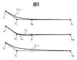
- FIG. 5 shows an example of a tool path that is approximated by a smoothing technique.
- the curve approximation has a characteristic that the path of the approximate curve changes greatly depending on the bending of the tool path, the coordinate value of the block end point, and the line segment distance between adjacent block end points. For this reason, when a curved surface is machined, the adjacent tool paths before and after become uneven, and there is a case where a smooth machining surface cannot be obtained due to a step between the adjacent tool paths.
- the adjacent tool path is a tool path having an interval corresponding to pick feed in reciprocating machining or contour line machining.
- Patent Document 1 is disclosed as an example of a related art relating to a smoothing technique capable of obtaining a smooth machined surface without causing a step between adjacent tool paths.
- Patent Document 1 relates to a numerical control device that suppresses the occurrence of a step between tool paths and can process a smooth curved surface in the pick feed direction.
- paragraph number 0019 wherein describing a specific configuration of the problem solving means described in paragraph 0005, "i.e., in the present embodiment, the path P i points P i neighboring, j, the point P i, j + 1 is the nearest distance segment connecting, by detecting a line segment connecting a point adjacent the front and rear of the path P i-1, P i + 1, the path P i of adjacent points P i, j , the curve portion of the path before and after the path passing through the point P i, j + 1 is detected, and the midpoint position f () of the smooth curve f (t) passing through the adjacent points P i, j and P i, j + 1.
- the method disclosed in Patent Document 1 has a problem that the tool path changes depending on the adjacent path even if the original tool path is the same.
- the present invention provides a tool path generation method capable of obtaining a smooth machining surface without generating a step between adjacent tool paths while making the generated tool paths the same if the original tool paths are the same. And an apparatus.
- a tool path generation method for machining a workpiece with a machine tool a tool path for machining a workpiece is read from a machining program, and equidistant on the read tool path.
- a tool path generation method sets a plurality of target points, calculates an approximate curve based on the plurality of target points, and generates a tool path along the approximate curve. Further, according to the present invention, in a tool path generation method for machining a workpiece with a machine tool, a tool path for machining a workpiece is read from a machining program, and a plurality of target points are set at equal intervals on the read tool path.
- a tool path generation method is provided, characterized in that it sets, calculates the average coordinates of adjacent target points, and generates a tool path connecting the average coordinates.
- a tool path generation method in which target points are set so that a linear distance between adjacent target points or a distance on a tool path is equal.
- a program reading / interpreting unit that reads a tool path from a machining program, and a plurality of target points at equal intervals on the tool path.
- a tool path generation apparatus including a target coordinate value calculation unit to be set and a calculation unit that generates a tool path from a plurality of target points.
- the calculation unit calculates an approximate curve for a plurality of target points to generate a tool path, or calculates an average coordinate of a plurality of adjacent target points
- a tool path generation device which is an average coordinate calculation unit for generating a path is provided.
- a plurality of target points are set on the tool path at equal intervals, and an approximate curve or average coordinate is calculated from the plurality of target points to calculate the tool path.
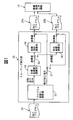
- FIG. 1 is a block diagram illustrating a configuration of a main part of a tool path generation apparatus according to the present invention.
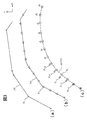
- FIG. 2 is a diagram illustrating an example of a tool path generation method.
- FIG. 3 is a diagram illustrating another example of a tool path generation method.
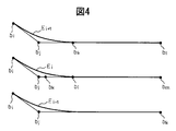
- FIG. 4 is an explanatory diagram illustrating a state in which no step is generated in adjacent tool paths.
- FIG. 5 is an explanatory diagram illustrating an example in which a step is generated in adjacent tool paths.
- the tool path generation device of the present invention is not limited to the form of the control device 15 used together with the numerically controlled machine tool 10 shown in this specification, and creates a machining program based on CAD data of a workpiece. It can also be used in the form of a CAM device, a numerically controlled machine tool incorporating a control device, or a personal computer. After reading the machining program created by the CAM device, the control device 15 can perform a smoothing process to generate a tool path, and can rewrite the machining program 20 based on the generated tool path.
- the rewritten machining programs 25A and 25B are stored in a memory in the apparatus, and can be read out for use with other machine tools, or the contents of the machining program can be partially edited.
- the apparatus can also be configured as a form that does not have a machining program rewrite function or a machining program memory function.
- the present control device can be applied to a vertical machining center having a vertical spindle, a horizontal machining center having a horizontal spindle, and other machine tools.
- the control device 15 of the present embodiment includes a smoothing execution unit 30 that performs a smoothing process on the block end point of the movement command of the machining program 20.
- the smoothing execution unit 30 includes a program reading / interpretation unit 32 that reads a tool path from the machining program 20, a target coordinate value calculation unit 34 that sets a plurality of target points at equal intervals on the read tool path, and a plurality of target points.
- the curve approximation calculation unit 36 that performs smoothing processing by curve approximation and the curve approximation calculation unit 36 are provided in parallel, and average coordinate calculation is performed by obtaining average coordinates from a plurality of adjacent target points and performing smoothing processing. Part 38.
- One of the curve approximation calculation unit 36 and the average coordinate calculation unit 38 can be selected by calculation method switching units 35 and 37.
- the smoothing execution unit 30 can output the machining program 25A or the machining program 25B rewritten based on the generated tool path to the numerically controlled machine tool 10.
- the program reading / interpreting unit 32 has a function of separating a cutting feed command and a machining command other than the cutting feed command from the machining program 20 created by the CAM.
- the machining command other than the cutting feed command is a curve approximation calculation.
- the data is transmitted to the downstream side of the unit 36 or the downstream side of the average coordinate calculation unit 38.
- the machining program 20 is rewritten based on the machining command and the generated tool path information.
- the program reading / interpreting unit 32 outputs a linear interpolation command or a curved interpolation command, which is a cutting feed movement command, among the feed axis movement commands of the machining program 20 to the target coordinate value calculation unit 34, and performs smoothing processing. That is, the program reading / interpreting unit 32 has a function of recognizing cutting feed and rapid feed, and is configured to perform the smoothing process only for a cutting feed movement command for performing cutting.
- FIG. 2 shows an example of the tool path ATP1 generated by the control device 15 of the present embodiment.
- Method for generating a tool path ATP1 shown in (c) of FIG. 2 includes the steps of reading a movement command of the feed axis from the machining program 20 created by the CAM system, connecting blocks endpoint b i movement command polyline (tool path ) Setting a plurality of target points p i on TP at equal intervals, and calculating approximate curves for the plurality of target points p i and generating a tool path ATP1 along the approximate curves. ing.
- FIG. 1 shows an example of the tool path ATP1 generated by the control device 15 of the present embodiment.
- Method for generating a tool path ATP1 shown in (c) of FIG. 2 includes the steps of reading a movement command of the feed axis from the machining program 20 created by the CAM system, connecting blocks endpoint b i movement command polyline (tool path ) Setting a plurality of target points p i on
- FIG. 2B shows a plurality of target points p i set at equal intervals on the tool path by the target coordinate value calculation unit 34.
- line TP has five segments regions of five blocks endpoints b i. The distance between the line segments between adjacent block end points b i is different.
- the plurality of target points p i set by the target coordinate value calculation unit 34 are divided so that the distances (paths) on the tool path between adjacent target points p i are equal. However, it is also possible to divide so that the linear distances between adjacent target points p i are equal.
- the number of target points p i is preferably larger than the number of block end points b i , and the tool path ATP1 closer to the original tool path can be generated as the number of target points p i increases.
- FIG. 2C shows a tool path ATP1 generated from a plurality of target points p i by the curve approximation calculation unit 36.
- NURBS curve approximation Bezier curve approximation, B-spline curve approximation, or the like can be applied.
- the curve fitting of the present invention the block end point b i of the move command is not referenced, set as the linear distance between the target point distance or adjacent the tool path between adjacent target points p i p i is constant use coordinate values of the target points p i, the smoothing processing is performed.
- the tool path ATP1 approximated by a curve is generated without a step between the adjacent tool paths E i ⁇ 1 , E i , and E i + 1 as shown in FIG. For this reason, a smooth curved surface having no step is generated on the processed surface of the workpiece.
- FIG. 3 shows another example of the tool path generated by the control device 15 of the present embodiment. Method for generating a tool path ATP2 shown in FIG.
- 3 (c) includes the steps of reading a movement command of the feed axis from the machining program 20 created by the CAM system, connecting blocks endpoint b i movement command polyline (tool path ) Setting a plurality of target points p i on TP at equal intervals, calculating average coordinates of a plurality of adjacent target points p i , and generating a tool path ATP2 connecting the average coordinates.
- FIG. 3C the tool path ATP2 smoothed by the average coordinate calculation unit 38 is shown.
- 3A is the same as FIG. 2A
- FIG. 3B is the same as FIG. 2B.
- the average coordinate calculator 38 calculates the average coordinates q i from the coordinate values of the plurality of target points p i by simple average or weighted average.
- the simple average for example, the coordinate values (x, y, z) of three points (p i ⁇ 1 , p i , p i + 1 ) of the target point p i and the target points before and after the target point p i are averaged to obtain an average coordinate of one point
- the coordinate value (x, y, z) of q i is obtained.
- the simple average is repeatedly performed on the coordinate values (x, y, z) of all the target points p i to obtain the coordinate values (x, y, z) of all the average coordinates q i .
- the weighted average is a method of calculating by weighting the coordinate values (x, y, z) of the target point p i to be averaged as in [Equation 1], and the target point p to be targeted This is a method of calculating by multiplying the coordinate value of the target point by a larger coefficient as the point is closer to i .
- the degree of smoothing can be adjusted by adjusting the number of target points to be averaged. When the number of target points is increased, the degree of smoothness increases and a smooth tool path can be obtained. When the number of target points is decreased, the degree of smoothness decreases and the target points p i A relatively sharp tool path close to can be obtained.
- Whether to perform simple averaging or weighted averaging is determined in consideration of the shape error of the tool path, the calculation speed of the apparatus, and the like.
- the smoothed tool path ATP2 is generated smoothly without a step between adjacent tool paths in the same manner as the tool path ATP1. For this reason, the smooth curved surface which does not have a level
- a plurality of target points p i are set at equal intervals on the tool path TP of the machining program created by the CAM device, and from the plurality of target points p i.
- a smooth machining surface can be obtained without generating a step between adjacent tool paths. Further, the obtained tool paths ATP1 and ATP2 have a smooth change in curvature, and can suppress a rapid change in acceleration. Thereby, since the impact at the time of a process is relieve
- this invention is not limited to the said embodiment, In the range which does not deviate from the main point of this invention, it can deform
Landscapes
- Engineering & Computer Science (AREA)
- Manufacturing & Machinery (AREA)
- Human Computer Interaction (AREA)
- Physics & Mathematics (AREA)
- General Physics & Mathematics (AREA)
- Automation & Control Theory (AREA)
- Computing Systems (AREA)
- Theoretical Computer Science (AREA)
- Mechanical Engineering (AREA)
- Numerical Control (AREA)
Abstract
Description
近年、工作機械の動作性能の向上により、加工プログラムに忠実に従って動作する工作機械が一般的なものとなり、このような工作機械を使用して加工すると、折れ線状に移動する工具の移動経路がそのままワークの加工面に転写されるものとなり、所望する滑らかな加工面が得られない場合があった。また、折れ線で近似された円弧や曲線を含む工具経路を高速で工具が移動すると、ブロック端点で送り軸に急激な加速度変化を生じ、加工の高速化の妨げになる場合もあった。これらを解決する方法として、CAM装置や数値制御工作機械の制御装置にて、加工プログラムの工具経路を数式表現可能なNURBSなどの近似曲線に置き換えて加工するスムージング技術が知られている。
図5には、スムージング技術により曲線近似された工具経路の一例が示されている。曲線近似には、工具経路の折れ曲がり具合や、ブロック端点の座標値や、隣接するブロック端点間の線分距離の僅かな違いで、近似曲線の経路が大きく変化する特性がある。このため、曲面の加工を行った場合に、隣り合う前後の工具経路が不揃いになり、隣り合う工具経路間で段差を生じて滑らかな加工面が得られない場合がある。ここで、隣り合う工具経路とは、往復加工や等高線加工でピックフィード分の間隔のあいた工具経路のことである。
隣り合う工具経路間で段差を生じることなく、滑らかな加工面を得ることができるスムージング技術に関する従来の一例として、特許文献1が開示されている。特許文献1は、工具経路間の段差発生を抑制し、ピックフィード方向にも滑らかな曲面を加工できるようにした数値制御装置に関するものである。段落番号0019には、段落番号0005に記載されている課題解決手段の具体的構成を説明する記載、「すなわち、本実施形態においては、当該パスPiの隣り合う点Pi,j、点Pi,j+1を結ぶ線分に一番近い距離にある、前後のパスPi−1、Pi+1の隣り合う点を結ぶ線分を検出することによって、当該パスPiの隣り合う点Pi,j、点Pi,j+1を通る曲線に近い前後のパスの曲線部を検出し、隣り合う点Pi,j、点Pi,j+1を通る滑らかな曲線f(t)の中間点位置f(1/2)と、前後のパスにおける検出した一番近い線分の両端の点を通る滑らか曲線g(t)、h(t)における垂線の足の位置に対応する該曲線上の位置g(tq)、h(tr)とにより、それぞれの位置に対して重みを付けて、Pi,j、と点Pi,j+1間に補助点PjHを挿入するものである。そして、この挿入した補助点をも指令点列とみなしパスPiの滑らか曲線を求めることによって、当該パスPiの前後のパスPi−1、Pi+1の曲線を考慮してパス間も滑らかに連続するようにしたものである。」がある。
上記目的を達成するために、本発明によれば、工作機械でワークを加工するための工具経路の生成方法において、加工プログラムからワークを加工する工具経路を読み出し、読み出した工具経路上に等間隔で複数の目標点を設定し、複数の目標点に基づいて近似曲線を演算し、近似曲線に沿った工具経路を生成することを特徴とした工具経路の生成方法が提供される。
また、本発明によれば、工作機械でワークを加工するための工具経路の生成方法において、加工プログラムからワークを加工する工具経路を読み出し、読み出した工具経路上に等間隔で複数の目標点を設定し、隣り合う目標点の平均座標を演算し、平均座標を結んだ工具経路を生成することを特徴とした工具経路の生成方法が提供される。
また、本発明によれば、目標点は、隣り合う目標点間の直線距離又は工具経路上の距離が等しくなるように設定される工具経路の生成方法が提供される。
また、本発明によれば、工作機械でワークを加工するための工具経路を生成する装置において、加工プログラムから工具経路を読み出すプログラム読取り解釈部と、工具経路上に等間隔で複数の目標点を設定する目標座標値演算部と、複数の目標点から工具経路を生成する演算部とを具備することを特徴とした工具経路の生成装置が提供される。
また、本発明によれば、演算部は、複数の目標点に対して近似曲線を演算して工具経路を生成する曲線近似演算部、又は隣り合う複数の目標点の平均座標を演算し、工具経路を生成する平均座標演算部である工具経路の生成装置が提供される。
以上の如く、本発明の工具経路の生成方法及び装置によれば、工具経路上に等間隔で複数の目標点を設定し、複数の目標点から近似曲線又は平均座標を演算して工具経路を生成することで、元の工具経路が同一ならば同じ工具経路が生成されるようになり、元の工具経路が類似する工具経路間では段差が発生せず、滑らかな加工面を得ることができる。
図2は、工具経路の生成方法の一例を示す図である。
図3は、工具経路の生成方法の他の例を示す図である。
図4は、隣り合う工具経路において段差が生じていない状態を示す説明図である。
図5は、隣り合う工具経路において段差が生じている一例を示す説明図である。
図1に示すように、本実施形態の制御装置15は、加工プログラム20の移動指令のブロック端点に対してスムージング処理を実施するスムージング実行部30を備えている。スムージング実行部30は、加工プログラム20から工具経路を読み出すプログラム読取り解釈部32と、読み出した工具経路上に等しい間隔で複数の目標点を設定する目標座標値演算部34と、複数の目標点に対して曲線近似によりスムージング処理を実施する曲線近似演算部36と、曲線近似演算部36とは並列に設けられ、隣り合う複数の目標点から平均座標を求めて、スムージング処理を実施する平均座標演算部38と、を有している。曲線近似演算部36と平均座標演算部38は、演算方式切換部35,37により一方の演算部36,38が選択可能になっている。
スムージング実行部30は、生成した工具経路に基づいて書き換えをした加工プログラム25A,又は加工プログラム25Bを数値制御工作機械10に対して出力することができる。プログラム読取り解釈部32は、CAMで作成された加工プログラム20から切削送り指令と、切削送り指令以外の加工指令を分離する機能を有しており、切削送り指令以外の加工指令は、曲線近似演算部36の下流側又は平均座標演算部38の下流側に送信される。加工指令と生成した工具経路の情報に基づいて加工プログラム20の書き換えが行われる。
プログラム読取り解釈部32は、加工プログラム20の送り軸の移動指令のうち、切削送りの移動指令である直線補間指令又は曲線補間指令を目標座標値演算部34に出力し、スムージング処理を行う。すなわち、プログラム読取り解釈部32は、切削送りと早送りとを認識する機能を有し、切削加工を実施する切削送りの移動指令に対してのみ、スムージング処理を実施するように構成されている。本実施形態では、早送りの送り軸の移動指令に対しては、スムージング処理は行なわれないが、必要に応じて早送りの指令にもスムージング処理を行うことができる。
図2には、本実施形態の制御装置15により生成された工具経路ATP1の一例が示されている。図2の(c)に示す工具経路ATP1の生成方法は、CAM装置で作成された加工プログラム20から送り軸の移動指令を読取るステップと、移動指令のブロック端点biを結んだ折れ線(工具経路)TP上に等間隔で複数の目標点piを設定するステップと、複数の目標点piに対する近似曲線を演算し、この近似曲線に沿った工具経路ATP1を生成するステップと、を有している。
図2の(b)には、目標座標値演算部34により工具経路上に等間隔で設定された複数の目標点piが示されている。図2の(a)に示すように、折れ線TPは5つのブロック端点biにより5つの線分領域を有している。隣り合うブロック端点bi間の線分の距離はそれぞれ異なっている。図2の(b)では、目標座標値演算部34により設定された複数の目標点piにより、隣り合う目標点pi間の工具経路上の距離(道のり)が等しくなるように分割されているが、隣り合う目標点pi間の直線距離が等しくなるように分割することもできる。目標点piの数は、ブロック端点biの数のより多くすることが好ましく、目標点piの数を多くするほど元の工具経路に近い工具経路ATP1を生成することができる。図2の(c)には、曲線近似演算部36により複数の目標点piから生成された工具経路ATP1が示されている。曲線近似には、NURBS曲線近似や、ベジェ曲線近似や、B−スプライン曲線近似などを適用することができる。本発明の曲線近似では、移動指令のブロック端点biは参照されず、隣り合う目標点pi間の工具経路上の距離又は隣り合う目標点pi間の直線距離が一定となるように設定された目標点piの座標値を使用して、スムージング処理が行われる。曲線近似された工具経路ATP1は、図4に示すように、隣り合う工具経路Ei−1,Ei,Ei+1間で段差を有さずに生成される。このため、ワークの加工面には、段差を有さない滑らかな曲面が生成される。
図3には、本実施形態の制御装置15により生成された工具経路の他の例が示されている。図3の(c)に示す工具経路ATP2の生成方法は、CAM装置で作成された加工プログラム20から送り軸の移動指令を読取るステップと、移動指令のブロック端点biを結んだ折れ線(工具経路)TP上に等間隔で複数の目標点piを設定するステップと、隣り合う複数の目標点piの平均座標を演算し、この平均座標を結んだ工具経路ATP2を生成するステップと、を有している。
図3の(c)には、平均座標演算部38によりスムージングされた工具経路ATP2が示されている。図3の(a)は図2の(a)と、図3の(b)は図2の(b)とそれぞれ同じである。平均座標演算部38では、単純平均又は加重平均により、複数の目標点piの座標値から平均座標qiを演算する。単純平均では、例えば目標点piとその前後の目標点の3点(pi−1,pi,pi+1)の座標値(x,y,z)を平均して、1点の平均座標qiの座標値(x,y,z)を求める。全ての目標点piの座標値(x,y,z)に対して単純平均を繰り返し実施することにより、全ての平均座標qiの座標値(x,y,z)を求める。加重平均は、[数1]のように平均化の対象となる目標点piの座標値(x,y,z)に対して重み付けをして計算する方法であり、対象となる目標点piからの距離が近い点ほど大きい係数を目標点の座標値に掛けて計算を行う方法である。

以上のように、本実施形態の制御装置15によれば、CAM装置で作成された加工プログラムの工具経路TP上に等間隔で複数の目標点piを設定し、複数の目標点piから近似曲線又は平均座標を演算して工具経路ATP1,ATP2を生成することで、隣り合う工具経路間で段差を発生せず、滑らかな加工面を得ることができる。
また、得られた工具経路ATP1,ATP2は曲率の変化も滑らかとなり、急激な加速度変化を抑制することができる。これにより、加工時の衝撃が和らげられるため、切削抵抗の変動が小さくなり、加工面品位を高めることができる。
なお、本発明は上記実施形態に限定されるものではなく、本発明の骨子を逸脱しない範囲で種々変形して実施することができる。
15 制御装置
30 スムージング実行部
32 プログラム読取り解釈部
34 目標座標値演算部
36 曲線近似演算部
38 平均座標演算部
TP 工具経路
ATP1、ATP2 スムージングされた工具経路
Claims (5)
- 工作機械でワークを加工するための工具経路の生成方法において、
加工プログラムからワークを加工する工具経路を読み出し、
前記読み出した工具経路上に等間隔で複数の目標点を設定し、
前記複数の目標点に基づいて近似曲線を演算し、
前記近似曲線に沿った工具経路を生成することを特徴とした工具経路の生成方法。 - 工作機械でワークを加工するための工具経路の生成方法において、
加工プログラムからワークを加工する工具経路を読み出し、
前記読み出した工具経路上に等間隔で複数の目標点を設定し、
隣り合う目標点の平均座標を演算し、
前記平均座標を結んだ工具経路を生成することを特徴とした工具経路の生成方法。 - 前記目標点は、隣り合う前記目標点間の直線距離又は前記工具経路上の距離が等しくなるように設定される請求項1又は2に記載の工具経路の生成方法。
- 工作機械でワークを加工するための工具経路を生成する装置において、
前記加工プログラムから工具経路を読み出すプログラム読取り解釈部と、前記工具経路上に等間隔で複数の目標点を設定する目標座標値演算部と、前記複数の目標点から工具経路を生成する演算部とを具備することを特徴とした工具経路の生成装置。 - 前記演算部は、前記複数の目標点に対して近似曲線を演算して工具経路を生成する曲線近似演算部、又は隣り合う複数の目標点の平均座標を演算し、工具経路を生成する平均座標演算部である請求項4に記載の工具経路の生成装置。
Priority Applications (3)
| Application Number | Priority Date | Filing Date | Title |
|---|---|---|---|
| EP10826930.9A EP2495628A4 (en) | 2009-10-30 | 2010-10-29 | METHOD AND DEVICE FOR TOOL PATH GENERATION |
| CN2010800486344A CN102640067A (zh) | 2009-10-30 | 2010-10-29 | 刀具路径的形成方法和装置 |
| US13/505,120 US20120215334A1 (en) | 2009-10-30 | 2010-10-29 | Tool path generation method and device |
Applications Claiming Priority (2)
| Application Number | Priority Date | Filing Date | Title |
|---|---|---|---|
| JP2009250638A JP2011096077A (ja) | 2009-10-30 | 2009-10-30 | 工具経路の生成方法及び装置 |
| JP2009-250638 | 2009-10-30 |
Publications (1)
| Publication Number | Publication Date |
|---|---|
| WO2011052800A1 true WO2011052800A1 (ja) | 2011-05-05 |
Family
ID=43922221
Family Applications (1)
| Application Number | Title | Priority Date | Filing Date |
|---|---|---|---|
| PCT/JP2010/069762 Ceased WO2011052800A1 (ja) | 2009-10-30 | 2010-10-29 | 工具経路の生成方法および装置 |
Country Status (6)
| Country | Link |
|---|---|
| US (1) | US20120215334A1 (ja) |
| EP (1) | EP2495628A4 (ja) |
| JP (1) | JP2011096077A (ja) |
| KR (1) | KR20120069745A (ja) |
| CN (1) | CN102640067A (ja) |
| WO (1) | WO2011052800A1 (ja) |
Cited By (4)
| Publication number | Priority date | Publication date | Assignee | Title |
|---|---|---|---|---|
| US20130138241A1 (en) * | 2011-11-28 | 2013-05-30 | Fanuc Corporation | Wire electric discharge machining method and wire electric discharge machine for machining tool that uses ultra-hard material and is mounted to rotating shaft |
| CN103135446A (zh) * | 2011-12-05 | 2013-06-05 | 中国科学院沈阳计算技术研究所有限公司 | 一种多轴数控机床刀具运动轨迹验证装置 |
| CN105955194A (zh) * | 2016-05-10 | 2016-09-21 | 大连理工大学 | 一种离散加工路径的拐点平滑方法 |
| US9715225B2 (en) | 2013-12-24 | 2017-07-25 | Fanuc Corporation | Numerical controller for smoothing tool path in operation based on table format data |
Families Citing this family (24)
| Publication number | Priority date | Publication date | Assignee | Title |
|---|---|---|---|---|
| WO2012056554A1 (ja) * | 2010-10-25 | 2012-05-03 | 株式会社牧野フライス製作所 | 工具経路の生成方法および生成装置 |
| EP2868411B1 (en) * | 2012-06-28 | 2018-08-08 | Makino Milling Machine Co., Ltd. | Control device for machine tool and machine tool |
| CN104703755B (zh) * | 2012-10-11 | 2017-10-24 | 株式会社牧野铣床制作所 | 刀具路径生成方法、机床的控制装置及刀具路径生成装置 |
| EP2915614B1 (en) | 2012-10-31 | 2020-09-02 | Makino Milling Machine Co., Ltd. | Machine tool control device and machine tool |
| DE112014006829T5 (de) * | 2014-07-23 | 2017-04-06 | Mitsubishi Electric Corporation | Anzeigevorrichtung und Anzeigeverfahren |
| CN104407569B (zh) * | 2014-10-21 | 2017-01-25 | 中国科学院长春光学精密机械与物理研究所 | 数控研抛中的进退刀路径规划方法 |
| US10248101B2 (en) * | 2014-10-29 | 2019-04-02 | Makino Milling Machine Co., Ltd. | Tool path generation method and machine tool using rate of change of curvature based smoothing |
| JP6145130B2 (ja) | 2015-04-28 | 2017-06-07 | ファナック株式会社 | 工具軸の軌跡を表示する軌跡表示装置 |
| JP6267156B2 (ja) * | 2015-05-29 | 2018-01-24 | ファナック株式会社 | 微小ブロックのコーナ制御を行うワイヤカット放電加工機用数値制御装置 |
| JP6672702B2 (ja) * | 2015-10-29 | 2020-03-25 | ブラザー工業株式会社 | 制御装置、工作機械、制御方法及びコンピュータプログラム |
| US10613516B2 (en) | 2016-04-07 | 2020-04-07 | Willemin-Macodel Sa | Method of optimization of machining programs |
| JP6386511B2 (ja) | 2016-10-28 | 2018-09-05 | ファナック株式会社 | 工具経路生成装置、工具経路生成方法及び工具経路生成プログラム |
| EP3603883B1 (en) * | 2017-03-31 | 2023-04-26 | Makino Milling Machine Co., Ltd. | Tool path generation method and device |
| JP6629808B2 (ja) | 2017-10-03 | 2020-01-15 | ファナック株式会社 | 数値制御装置 |
| JP6823032B2 (ja) * | 2018-10-25 | 2021-01-27 | ファナック株式会社 | プログラム修正装置 |
| WO2020178978A1 (ja) | 2019-03-05 | 2020-09-10 | 三菱電機株式会社 | 加工プログラム変換装置、数値制御装置および加工プログラム変換方法 |
| CN109918807B (zh) * | 2019-03-13 | 2022-03-11 | 西北工业大学 | 一种优化曲率的局部刀轨光顺方法 |
| JP6863497B1 (ja) * | 2020-03-11 | 2021-04-21 | オムロン株式会社 | コントローラシステムおよびその制御方法 |
| KR102423658B1 (ko) * | 2020-12-01 | 2022-07-22 | 엘에스일렉트릭(주) | 다수 공작물 좌표계 간의 모션 제어 방법, 장치 및 시스템 |
| TWI742981B (zh) * | 2021-01-06 | 2021-10-11 | 財團法人工業技術研究院 | 加工路徑過切分析方法 |
| CN114952412B (zh) * | 2022-07-11 | 2023-06-23 | 捷普电子(新加坡)公司 | 刀具的设计方法及刀具的加工路径生成方法 |
| CN116954149B (zh) * | 2023-07-28 | 2026-01-23 | 烟台大学 | 一种三阶几何连续的刀具路径平滑压缩方法 |
| CN118192407B (zh) * | 2024-04-07 | 2024-09-20 | 苏州铼钠克信息技术有限公司 | 螺旋曲面加工路径的局部光顺方法及相关装置 |
| CN119861657A (zh) * | 2025-01-03 | 2025-04-22 | 烟台大学 | 适用于五轴数控加工的刀具路径拐角非对称平滑方法 |
Citations (4)
| Publication number | Priority date | Publication date | Assignee | Title |
|---|---|---|---|---|
| JPH09265310A (ja) * | 1996-03-29 | 1997-10-07 | Toyota Motor Corp | 工具点列発生方法 |
| JP2000353006A (ja) | 1999-06-10 | 2000-12-19 | Fanuc Ltd | 数値制御装置 |
| JP2002283099A (ja) * | 2001-03-22 | 2002-10-02 | Koatec Kk | 溶接部位仕上げ方法及び装置 |
| JP2003067020A (ja) * | 2001-08-28 | 2003-03-07 | Mitsubishi Electric Corp | 速度制御装置、速度制御方法およびその方法をコンピュータに実行させるプログラム |
Family Cites Families (28)
| Publication number | Priority date | Publication date | Assignee | Title |
|---|---|---|---|---|
| JPS63204413A (ja) * | 1987-02-20 | 1988-08-24 | Fanuc Ltd | 曲面創成方法 |
| JPH04333105A (ja) * | 1991-05-08 | 1992-11-20 | Mitsubishi Heavy Ind Ltd | ロボットの軌跡制御方法 |
| JPH06339850A (ja) * | 1993-06-01 | 1994-12-13 | Yaskawa Electric Corp | みがき装置におけるみがき面教示方法 |
| JP3765546B2 (ja) * | 1994-01-25 | 2006-04-12 | ダイキン工業株式会社 | 曲面教示方法およびその装置 |
| US5566288A (en) * | 1994-09-02 | 1996-10-15 | Caterpillar Inc. | System and method for automatically fitting a B-spline curve to a set of data points |
| US5717905A (en) * | 1994-12-15 | 1998-02-10 | Kao Corporation | CAD system and bezier-curve data converting apparatus and method thereof in said CAD system |
| EP0890890B1 (en) * | 1996-03-26 | 2008-05-28 | Toyota Jidosha Kabushiki Kaisha | Method and apparatus for preparing data on tool moving path, and machining method and system |
| JP3593850B2 (ja) * | 1996-06-17 | 2004-11-24 | トヨタ自動車株式会社 | 工具点列発生方法 |
| JP3366213B2 (ja) * | 1997-02-26 | 2003-01-14 | 三菱電機株式会社 | 曲線の微小線分化方法およびスプライン補間機能を有する数値制御装置 |
| KR100363814B1 (ko) * | 1998-05-28 | 2002-12-06 | 미쓰비시덴키 가부시키가이샤 | 수치제어장치를위한가공프로그램의파일컨버터장치및파일컨버터의순서를컴퓨터에실행시키는프로그램을저장한컴퓨터판독가능한기록매체 |
| US6934601B2 (en) * | 1999-09-20 | 2005-08-23 | Hitachi, Ltd. | Numerically controlled curved surface machining unit |
| JP3610485B2 (ja) * | 1999-09-20 | 2005-01-12 | 株式会社日立製作所 | 数値制御曲面加工装置 |
| US6595151B2 (en) * | 2001-05-31 | 2003-07-22 | K2 Keller Consulting | Planing sailboard |
| AU2001281094A1 (en) * | 2001-08-06 | 2003-02-24 | Micron Technology, Inc. | Interpolation error minimization for data reduction |
| JP2003076410A (ja) * | 2001-08-30 | 2003-03-14 | Mitsubishi Electric Corp | 速度制御装置、速度制御方法およびその方法をコンピュータに実行させるプログラム |
| DE10157964B4 (de) * | 2001-11-26 | 2011-06-22 | Siemens AG, 80333 | Verfahren zur Optimierung einer Oberflächengüte eines zu fertigenden Werkstücks anhand von CNC-Programmdaten |
| JP3904993B2 (ja) * | 2002-08-16 | 2007-04-11 | ファナック株式会社 | 曲線補間方法 |
| FR2848001A1 (fr) * | 2002-11-29 | 2004-06-04 | Francois Nadal | Procede et systeme pour, en temps reel, anticiper, identifier, analyser et repondre a des besoins des consomateurs |
| JP4271487B2 (ja) * | 2003-05-19 | 2009-06-03 | 東芝機械株式会社 | 数値制御装置及び数値制御方法 |
| DE10357650B4 (de) * | 2003-12-10 | 2019-04-25 | Dr. Johannes Heidenhain Gmbh | Verfahren zur Glättung von Polygonzügen in NC-Programmen |
| US7792604B2 (en) * | 2005-03-23 | 2010-09-07 | Hurco Companies, Inc. | Method of performing additive lookahead for adaptive cutting feedrate control |
| JP2006309645A (ja) * | 2005-05-02 | 2006-11-09 | Fanuc Ltd | 曲線補間方法 |
| JP4800873B2 (ja) * | 2006-08-04 | 2011-10-26 | オークマ株式会社 | 近似点群データからの近似曲線生成プログラム及び方法 |
| CN100533316C (zh) * | 2007-07-20 | 2009-08-26 | 天津大学 | 一种金刚石超精密车床自由曲面加工路径生成方法 |
| CN100582975C (zh) * | 2008-06-19 | 2010-01-20 | 上海交通大学 | 五轴数控加工安全最短刀具长度的规划方法 |
| DE102009008124A1 (de) * | 2009-02-09 | 2010-08-19 | Deckel Maho Pfronten Gmbh | Verfahren und Vorrichtung zum Erzeugen von Steuerdaten zum Steuern eines Werkzeugs an einer zumindest 5 Achsen umfassenden Werkzeugmaschine |
| CN102428419B (zh) * | 2009-06-03 | 2013-12-25 | 三菱电机株式会社 | 数控装置以及生产系统 |
| EP2634659B1 (en) * | 2010-10-26 | 2016-11-30 | Makino Milling Machine Co., Ltd. | Method and device for generating tool path |
-
2009
- 2009-10-30 JP JP2009250638A patent/JP2011096077A/ja active Pending
-
2010
- 2010-10-29 CN CN2010800486344A patent/CN102640067A/zh active Pending
- 2010-10-29 EP EP10826930.9A patent/EP2495628A4/en not_active Withdrawn
- 2010-10-29 WO PCT/JP2010/069762 patent/WO2011052800A1/ja not_active Ceased
- 2010-10-29 US US13/505,120 patent/US20120215334A1/en not_active Abandoned
- 2010-10-29 KR KR1020127010408A patent/KR20120069745A/ko not_active Ceased
Patent Citations (4)
| Publication number | Priority date | Publication date | Assignee | Title |
|---|---|---|---|---|
| JPH09265310A (ja) * | 1996-03-29 | 1997-10-07 | Toyota Motor Corp | 工具点列発生方法 |
| JP2000353006A (ja) | 1999-06-10 | 2000-12-19 | Fanuc Ltd | 数値制御装置 |
| JP2002283099A (ja) * | 2001-03-22 | 2002-10-02 | Koatec Kk | 溶接部位仕上げ方法及び装置 |
| JP2003067020A (ja) * | 2001-08-28 | 2003-03-07 | Mitsubishi Electric Corp | 速度制御装置、速度制御方法およびその方法をコンピュータに実行させるプログラム |
Non-Patent Citations (1)
| Title |
|---|
| See also references of EP2495628A4 |
Cited By (6)
| Publication number | Priority date | Publication date | Assignee | Title |
|---|---|---|---|---|
| US20130138241A1 (en) * | 2011-11-28 | 2013-05-30 | Fanuc Corporation | Wire electric discharge machining method and wire electric discharge machine for machining tool that uses ultra-hard material and is mounted to rotating shaft |
| US9381589B2 (en) * | 2011-11-28 | 2016-07-05 | Fanuc Corporation | Wire electric discharge machining method and wire electric discharge machine for machining tool that uses ultra-hard material and is mounted to rotating shaft |
| CN103135446A (zh) * | 2011-12-05 | 2013-06-05 | 中国科学院沈阳计算技术研究所有限公司 | 一种多轴数控机床刀具运动轨迹验证装置 |
| US9715225B2 (en) | 2013-12-24 | 2017-07-25 | Fanuc Corporation | Numerical controller for smoothing tool path in operation based on table format data |
| CN105955194A (zh) * | 2016-05-10 | 2016-09-21 | 大连理工大学 | 一种离散加工路径的拐点平滑方法 |
| CN105955194B (zh) * | 2016-05-10 | 2018-09-04 | 大连理工大学 | 一种离散加工路径的拐点平滑方法 |
Also Published As
| Publication number | Publication date |
|---|---|
| EP2495628A1 (en) | 2012-09-05 |
| JP2011096077A (ja) | 2011-05-12 |
| EP2495628A4 (en) | 2013-07-10 |
| KR20120069745A (ko) | 2012-06-28 |
| US20120215334A1 (en) | 2012-08-23 |
| CN102640067A (zh) | 2012-08-15 |
Similar Documents
| Publication | Publication Date | Title |
|---|---|---|
| JP2011096077A (ja) | 工具経路の生成方法及び装置 | |
| JP6257796B2 (ja) | 工具経路の生成方法および工作機械 | |
| JP5615377B2 (ja) | 工具経路の生成方法および生成装置 | |
| JP6548830B2 (ja) | 指令値生成装置 | |
| JP2010511919A (ja) | 許容差ベースの経路設計と制御の方法 | |
| CN109597359B (zh) | 数值控制装置 | |
| CN114488941B (zh) | 微小线段的轨迹光顺方法、介质及机床数控设备 | |
| CN113835397B (zh) | 基于b样条曲线和路径积分的线性数控加工路径平滑方法 | |
| CN116795044B (zh) | 速度规划方法、装置、机床控制系统和存储介质 | |
| CN118339426A (zh) | 加工物体表面的表面拟合、路径规划以及用于加工物体表面的系统和方法 | |
| CN113504764A (zh) | 基于位置矢量加权积分的连续线段数控加工路径平滑方法 | |
| CN110879572B (zh) | 数控装置及数控方法 | |
| JPH10240328A (ja) | 数値制御装置 | |
| JP4969484B2 (ja) | 数値制御装置 | |
| CN108351635A (zh) | 用于提供行程轮廓的方法、控制装置、机器和计算机程序 | |
| JP2000311010A (ja) | 軌跡制御装置、プログラム作成装置およびプログラム変換装置 | |
| JP2003223208A (ja) | 数値制御システム | |
| CN115210662A (zh) | 数值控制装置 | |
| CN119292185B (zh) | 基于多模型的加工路径插补数控系统及机床 | |
| JP2007156604A (ja) | 曲面作成方法及び曲面作成プログラム並びに3次元形状処理装置 | |
| CN120901759A (zh) | 基于最小二乘法的高速圆锯机锯切方法及系统 | |
| JP3562576B2 (ja) | 数値制御装置の曲線補間方法 | |
| JP2013008276A (ja) | 切削加工経路創成装置及び方法並びにプログラム | |
| WO2016199266A1 (ja) | 数値制御装置 | |
| CN120972760A (zh) | 加工轨迹曲线拟合方法、装置、介质、计算设备和产品 |
Legal Events
| Date | Code | Title | Description |
|---|---|---|---|
| WWE | Wipo information: entry into national phase |
Ref document number: 201080048634.4 Country of ref document: CN |
|
| 121 | Ep: the epo has been informed by wipo that ep was designated in this application |
Ref document number: 10826930 Country of ref document: EP Kind code of ref document: A1 |
|
| ENP | Entry into the national phase |
Ref document number: 20127010408 Country of ref document: KR Kind code of ref document: A |
|
| NENP | Non-entry into the national phase |
Ref country code: DE |
|
| WWE | Wipo information: entry into national phase |
Ref document number: 13505120 Country of ref document: US |
|
| WWE | Wipo information: entry into national phase |
Ref document number: 2010826930 Country of ref document: EP |