WO2011055802A1 - プロピレン重合反応装置及びプロピレン系重合体の製造方法 - Google Patents
プロピレン重合反応装置及びプロピレン系重合体の製造方法 Download PDFInfo
- Publication number
- WO2011055802A1 WO2011055802A1 PCT/JP2010/069752 JP2010069752W WO2011055802A1 WO 2011055802 A1 WO2011055802 A1 WO 2011055802A1 JP 2010069752 W JP2010069752 W JP 2010069752W WO 2011055802 A1 WO2011055802 A1 WO 2011055802A1
- Authority
- WO
- WIPO (PCT)
- Prior art keywords
- propylene
- polymerization
- reaction
- tank
- polymer
- Prior art date
- Legal status (The legal status is an assumption and is not a legal conclusion. Google has not performed a legal analysis and makes no representation as to the accuracy of the status listed.)
- Ceased
Links
Images







Classifications
-
- C—CHEMISTRY; METALLURGY
- C08—ORGANIC MACROMOLECULAR COMPOUNDS; THEIR PREPARATION OR CHEMICAL WORKING-UP; COMPOSITIONS BASED THEREON
- C08F—MACROMOLECULAR COMPOUNDS OBTAINED BY REACTIONS ONLY INVOLVING CARBON-TO-CARBON UNSATURATED BONDS
- C08F10/00—Homopolymers and copolymers of unsaturated aliphatic hydrocarbons having only one carbon-to-carbon double bond
- C08F10/04—Monomers containing three or four carbon atoms
- C08F10/06—Propene
-
- B—PERFORMING OPERATIONS; TRANSPORTING
- B01—PHYSICAL OR CHEMICAL PROCESSES OR APPARATUS IN GENERAL
- B01J—CHEMICAL OR PHYSICAL PROCESSES, e.g. CATALYSIS OR COLLOID CHEMISTRY; THEIR RELEVANT APPARATUS
- B01J19/00—Chemical, physical or physico-chemical processes in general; Their relevant apparatus
- B01J19/18—Stationary reactors having moving elements inside
-
- B—PERFORMING OPERATIONS; TRANSPORTING
- B01—PHYSICAL OR CHEMICAL PROCESSES OR APPARATUS IN GENERAL
- B01J—CHEMICAL OR PHYSICAL PROCESSES, e.g. CATALYSIS OR COLLOID CHEMISTRY; THEIR RELEVANT APPARATUS
- B01J8/00—Chemical or physical processes in general, conducted in the presence of fluids and solid particles; Apparatus for such processes
- B01J8/0015—Feeding of the particles in the reactor; Evacuation of the particles out of the reactor
- B01J8/003—Feeding of the particles in the reactor; Evacuation of the particles out of the reactor in a downward flow
-
- B—PERFORMING OPERATIONS; TRANSPORTING
- B01—PHYSICAL OR CHEMICAL PROCESSES OR APPARATUS IN GENERAL
- B01J—CHEMICAL OR PHYSICAL PROCESSES, e.g. CATALYSIS OR COLLOID CHEMISTRY; THEIR RELEVANT APPARATUS
- B01J8/00—Chemical or physical processes in general, conducted in the presence of fluids and solid particles; Apparatus for such processes
- B01J8/18—Chemical or physical processes in general, conducted in the presence of fluids and solid particles; Apparatus for such processes with fluidised particles
- B01J8/1818—Feeding of the fluidising gas
- B01J8/1827—Feeding of the fluidising gas the fluidising gas being a reactant
-
- B—PERFORMING OPERATIONS; TRANSPORTING
- B01—PHYSICAL OR CHEMICAL PROCESSES OR APPARATUS IN GENERAL
- B01J—CHEMICAL OR PHYSICAL PROCESSES, e.g. CATALYSIS OR COLLOID CHEMISTRY; THEIR RELEVANT APPARATUS
- B01J8/00—Chemical or physical processes in general, conducted in the presence of fluids and solid particles; Apparatus for such processes
- B01J8/18—Chemical or physical processes in general, conducted in the presence of fluids and solid particles; Apparatus for such processes with fluidised particles
- B01J8/20—Chemical or physical processes in general, conducted in the presence of fluids and solid particles; Apparatus for such processes with fluidised particles with liquid as a fluidising medium
-
- B—PERFORMING OPERATIONS; TRANSPORTING
- B01—PHYSICAL OR CHEMICAL PROCESSES OR APPARATUS IN GENERAL
- B01J—CHEMICAL OR PHYSICAL PROCESSES, e.g. CATALYSIS OR COLLOID CHEMISTRY; THEIR RELEVANT APPARATUS
- B01J8/00—Chemical or physical processes in general, conducted in the presence of fluids and solid particles; Apparatus for such processes
- B01J8/18—Chemical or physical processes in general, conducted in the presence of fluids and solid particles; Apparatus for such processes with fluidised particles
- B01J8/24—Chemical or physical processes in general, conducted in the presence of fluids and solid particles; Apparatus for such processes with fluidised particles according to "fluidised-bed" technique
- B01J8/38—Chemical or physical processes in general, conducted in the presence of fluids and solid particles; Apparatus for such processes with fluidised particles according to "fluidised-bed" technique with fluidised bed containing a rotatable device or being subject to rotation or to a circulatory movement, i.e. leaving a vessel and subsequently re-entering it
- B01J8/382—Chemical or physical processes in general, conducted in the presence of fluids and solid particles; Apparatus for such processes with fluidised particles according to "fluidised-bed" technique with fluidised bed containing a rotatable device or being subject to rotation or to a circulatory movement, i.e. leaving a vessel and subsequently re-entering it with a rotatable device only
-
- B—PERFORMING OPERATIONS; TRANSPORTING
- B01—PHYSICAL OR CHEMICAL PROCESSES OR APPARATUS IN GENERAL
- B01J—CHEMICAL OR PHYSICAL PROCESSES, e.g. CATALYSIS OR COLLOID CHEMISTRY; THEIR RELEVANT APPARATUS
- B01J2208/00—Processes carried out in the presence of solid particles; Reactors therefor
- B01J2208/00008—Controlling the process
- B01J2208/00017—Controlling the temperature
- B01J2208/00106—Controlling the temperature by indirect heat exchange
- B01J2208/00168—Controlling the temperature by indirect heat exchange with heat exchange elements outside the bed of solid particles
- B01J2208/00247—Reflux columns
-
- B—PERFORMING OPERATIONS; TRANSPORTING
- B01—PHYSICAL OR CHEMICAL PROCESSES OR APPARATUS IN GENERAL
- B01J—CHEMICAL OR PHYSICAL PROCESSES, e.g. CATALYSIS OR COLLOID CHEMISTRY; THEIR RELEVANT APPARATUS
- B01J2208/00—Processes carried out in the presence of solid particles; Reactors therefor
- B01J2208/00008—Controlling the process
- B01J2208/00017—Controlling the temperature
- B01J2208/00106—Controlling the temperature by indirect heat exchange
- B01J2208/00265—Part of all of the reactants being heated or cooled outside the reactor while recycling
- B01J2208/00274—Part of all of the reactants being heated or cooled outside the reactor while recycling involving reactant vapours
-
- B—PERFORMING OPERATIONS; TRANSPORTING
- B01—PHYSICAL OR CHEMICAL PROCESSES OR APPARATUS IN GENERAL
- B01J—CHEMICAL OR PHYSICAL PROCESSES, e.g. CATALYSIS OR COLLOID CHEMISTRY; THEIR RELEVANT APPARATUS
- B01J2219/00—Chemical, physical or physico-chemical processes in general; Their relevant apparatus
- B01J2219/00002—Chemical plants
- B01J2219/00027—Process aspects
- B01J2219/00033—Continuous processes
-
- B—PERFORMING OPERATIONS; TRANSPORTING
- B01—PHYSICAL OR CHEMICAL PROCESSES OR APPARATUS IN GENERAL
- B01J—CHEMICAL OR PHYSICAL PROCESSES, e.g. CATALYSIS OR COLLOID CHEMISTRY; THEIR RELEVANT APPARATUS
- B01J2219/00—Chemical, physical or physico-chemical processes in general; Their relevant apparatus
- B01J2219/00002—Chemical plants
- B01J2219/00027—Process aspects
- B01J2219/0004—Processes in series
-
- B—PERFORMING OPERATIONS; TRANSPORTING
- B01—PHYSICAL OR CHEMICAL PROCESSES OR APPARATUS IN GENERAL
- B01J—CHEMICAL OR PHYSICAL PROCESSES, e.g. CATALYSIS OR COLLOID CHEMISTRY; THEIR RELEVANT APPARATUS
- B01J2219/00—Chemical, physical or physico-chemical processes in general; Their relevant apparatus
- B01J2219/18—Details relating to the spatial orientation of the reactor
- B01J2219/182—Details relating to the spatial orientation of the reactor horizontal
-
- C—CHEMISTRY; METALLURGY
- C08—ORGANIC MACROMOLECULAR COMPOUNDS; THEIR PREPARATION OR CHEMICAL WORKING-UP; COMPOSITIONS BASED THEREON
- C08F—MACROMOLECULAR COMPOUNDS OBTAINED BY REACTIONS ONLY INVOLVING CARBON-TO-CARBON UNSATURATED BONDS
- C08F110/00—Homopolymers of unsaturated aliphatic hydrocarbons having only one carbon-to-carbon double bond
- C08F110/04—Monomers containing three or four carbon atoms
- C08F110/06—Propene
-
- C—CHEMISTRY; METALLURGY
- C08—ORGANIC MACROMOLECULAR COMPOUNDS; THEIR PREPARATION OR CHEMICAL WORKING-UP; COMPOSITIONS BASED THEREON
- C08F—MACROMOLECULAR COMPOUNDS OBTAINED BY REACTIONS ONLY INVOLVING CARBON-TO-CARBON UNSATURATED BONDS
- C08F210/00—Copolymers of unsaturated aliphatic hydrocarbons having only one carbon-to-carbon double bond
- C08F210/04—Monomers containing three or four carbon atoms
- C08F210/06—Propene
Definitions
- the present invention relates to a propylene polymerization reactor and a method for producing a propylene polymer, and more specifically, in a multistage continuous gas phase polymerization method of a propylene polymer using an olefin polymerization catalyst, with low cost and high productivity.
- the present invention relates to a propylene polymerization reaction apparatus and a method for producing a propylene-based polymer that can be stably produced and can produce a high-quality continuous multistage polymer. More specifically, in the multi-stage continuous gas phase polymerization method, the amount of non-standard products generated by changing the polymerization conditions can be greatly reduced without lowering the productivity, and the rigidity / impact strength balance is excellent.
- the present invention relates to a propylene polymerization reactor and a method for producing a propylene polymer.
- Polypropylene resin has been used in various fields since it is relatively inexpensive and has excellent characteristics. However, various improvements have been made with polypropylene alone because its use is limited. For example, in order to improve impact resistance, homopolypropylene is first polymerized and then propylene-based block copolymer obtained by copolymerization of propylene and ethylene, or polypropylene with different molecular weights to improve moldability and appearance. Propylene-based polymers and the like that have been manufactured and have an expanded molecular weight distribution have been proposed.
- each component is manufactured individually and then kneaded again at a predetermined ratio, but each component is continuously added due to economic concerns and the risk of quality deterioration due to kneading.
- a continuous multi-stage polymerization process is preferred.
- the polymer particles are almost completely mixed in one container, it is easy for the particles that are not sufficiently grown to be discharged and the particles that have grown too much to accumulate in the container. As a result, the quality of the polymer is deteriorated.
- a known horizontal reactor having a stirrer that rotates about a horizontal axis is known as a known reactor that achieves plug flow by reducing the residence time distribution in one reaction tank (a horizontal gas phase process, for example, Patent Document 1.
- the reactor is also referred to as a reaction vessel).
- the catalyst particles gradually grow into polymer particles due to the polymerization reaction, but when polymerization is performed in a horizontal reactor, these particles gradually grow due to the two forces of formation of polypropylene by polymerization and mechanical stirring. It progresses along the axial direction of the reactor while growing. For this reason, the particles having the same degree of growth, that is, the residence time are aligned with time from the upstream side to the downstream side of the reactor.
- the fluid flow pattern is a plug flow type, which has the effect of narrowing the residence time distribution to the same extent as when a plurality of fully mixed reaction tanks are arranged in series. Therefore, in the production of the polymer, a propylene polymerization reactor comprising a plurality of horizontal reactors connected in series is advantageous.
- a component having a low molecular weight or a component having a large amount of components such as ethylene is produced in a certain polymerization step.
- the latent heat of liquefied propylene is used to remove the heat of polymerization.
- the liquefied propylene there is a case where unreacted propylene gas is extracted from the polymerization reaction tank and liquefied by cooling with a heat exchanger. The temperature at which the unreacted gas liquefies (dew point) depends on the pressure and the composition of the unreacted gas.
- the horizontal gas phase process has excellent plug flow characteristics, but productivity and operation cost are required when producing a multistage polymer having a low molecular weight component or a component containing a large amount of ethylene. Have problems to be solved.
- crystalline polypropylene is inexpensive and has excellent characteristics such as rigidity and heat resistance, but has a problem that impact resistance strength, particularly impact strength at low temperatures is weak.
- a method for improving this point a method is known in which propylene and ⁇ -olefin or other olefins are polymerized stepwise to form a block copolymer.
- the propylene block copolymer comprises a crystalline propylene polymer part and an amorphous propylene / ⁇ -olefin copolymer part, and can adjust a molded product having high rigidity and excellent low-temperature impact resistance. For this reason, it is widely used in applications such as automobile parts and household appliance parts.
- molded articles made of polyolefin used for automobiles and home appliances have applications that require gloss, while molded articles with low gloss have a high-class feeling, and therefore have applications that require low gloss.
- materials exhibiting low gloss are desired.
- impact resistance is imparted mainly by increasing the content of the amorphous propylene / ⁇ -olefin copolymer, and suppression of gloss is achieved by the amorphous propylene / ⁇ -olefin copolymer. This is achieved by increasing the molecular weight of the polymer and the ⁇ -olefin content.
- these methods increase the gel in the propylene-based block copolymer, and a large amount of gel not only deteriorates the appearance of the product but also decreases the impact resistance.
- the main cause of gel generation was a distribution in the polymerization time (residence time in the polymerization tank) of the catalyst component in the first stage polymerization process in the multistage continuous gas phase polymerization method, which was discharged from the polymerization tank in a relatively short time.
- the particles short pass particles
- the batch method has a problem that it is inferior in terms of economy and productivity.
- a method for producing a propylene-based block copolymer having low gloss by a multistage continuous gas phase polymerization method a method for increasing the molecular weight or ⁇ -olefin content of an amorphous propylene / ⁇ -olefin copolymer (for example, patent References 2 and 3) are disclosed, but the first stage polymerization step is carried out in a complete mixing tank, and therefore a problem remains in terms of gel suppression.
- a method using a horizontal reactor is known as a polymerization method in which gel is suppressed (see, for example, Patent Document 1).
- the residence time distribution in the reaction vessel is narrow, and the reduction of short path particles can be obtained in one reaction vessel, which is advantageous in terms of gel suppression. Since it is carried out with latent heat, the gas composition inside the reactor becomes non-uniform, and in the production of an amorphous propylene / ⁇ -olefin copolymer, there is a problem that composition distribution occurs and gloss tends to be high.
- a copolymer component having a higher ⁇ -olefin content by connecting the three reaction vessels in series and performing the first stage polymerization step (see, for example, Patent Document 4). It is disclosed.
- hydrogen is generally used as a molecular weight regulator, but when a large amount of hydrogen is supplied to obtain a low molecular weight polymer in the first stage polymerization step. Even if an attempt is made to obtain a high molecular weight copolymer without supplying hydrogen in the second-stage polymerization step, hydrogen in the entrained gas from the reactor in the first-stage polymerization step is always the reactor in the second-stage polymerization step. As a result, the molecular weight side of the copolymer that can be produced in the second stage polymerization step is limited.
- Patent Document 6 a method of diluting the entrained gas with an inert gas in a receiver provided between the polymerization reactors, lowering the gas composition of hydrogen, and then transferring it to the second stage polymerization step.
- Patent Document 7 a method of diluting the entrained gas with an inert gas in a receiver provided between the polymerization reactors, lowering the gas composition of hydrogen, and then transferring it to the second stage polymerization step.
- Patent Document 7 a method of diluting the entrained gas with an inert gas in a receiver provided between the polymerization reactors, lowering the gas composition of hydrogen, and then transferring it to the second stage polymerization step.
- high fluidization of a propylene-based block copolymer is mainly achieved by high fluidization (reducing molecular weight) of a crystalline propylene polymer portion.
- Another method is to lower the molecular weight of the amorphous propylene / ⁇ -olefin copolymer component, but this method also reduces the low-temperature impact resistance of the propylene-based block copolymer at the same time. It is not preferable for achieving the object.
- a molecular weight modifier such as hydrogen is used to adjust the molecular weight of the crystalline propylene component, but in order to express the high fluidity of the propylene-based block copolymer desired by the present invention in particular, It is necessary to maintain a high hydrogen concentration in the polymerization reactor in the one-stage polymerization process and to maintain a low hydrogen concentration in the copolymerization process.
- Patent Documents 2 and 3 As a method for producing a propylene-based block copolymer with improved impact resistance by a multistage continuous gas phase polymerization method, a method for increasing the molecular weight and ⁇ -olefin content of an amorphous propylene / ⁇ -olefin copolymer (for example, Patent Documents 2 and 3) are disclosed, but since the first stage polymerization step is performed in a complete mixing tank, there remains a problem in terms of gel suppression. On the other hand, a method using a horizontal reactor is known as a polymerization method in which gel is suppressed (see, for example, Patent Document 5).
- the residence time distribution in the reaction vessel is narrow, and the reduction of short path particles can be obtained in one reaction vessel, which is advantageous in terms of gel suppression.
- the ⁇ -olefin used in the second-stage polymerization step uses a comonomer having a low boiling point such as ethylene, it has a problem that it is difficult to condense the unreacted gas and the comonomer content cannot be increased. ing.
- two horizontal reaction vessels are used, it is difficult to produce a desired high molecular weight copolymer component due to hydrogen leakage from the first reactor in the case of continuous operation.
- Patent Documents 4 and 9 disclose (for example, see Patent Documents 4 and 9).
- the method of Patent Document 4 it is necessary to limit the molecular weight of each tank for gel suppression, and there is a problem to further increase the molecular weight of the amorphous propylene / ⁇ -olefin copolymer component.
- the method of Patent Document 9 has a problem in that it can be produced with good productivity while maintaining the quality of the propylene-based block copolymer, such as the need to limit the production rate in the first stage polymerization step. Yes.
- the amount of the electron donating compound added to the second tank and the third tank is A defining method (for example, see Patent Document 10) has been proposed.
- Patent Document 10 A defining method (for example, see Patent Document 10) has been proposed.
- the object of the present invention is to produce a propylene-based polymer using a catalyst for olefin polymerization in a multistage continuous gas phase polymerization method with low cost and high productivity.
- An object of the present invention is to provide a propylene polymerization reactor capable of producing a high-quality continuous multistage polymer and a method for producing a propylene-based polymer. More specifically, in the multi-stage continuous gas phase polymerization method, the amount of non-standard products generated by changing the polymerization conditions can be greatly reduced without lowering the productivity, and the rigidity / impact strength balance is excellent.
- An object of the present invention is to provide a propylene polymerization reactor and a method for producing a propylene-based polymer.
- a reaction apparatus for producing a propylene-based polymer by a multistage continuous gas phase polymerization method which has a stirrer that rotates about a horizontal axis therein. And at least one complete mixing tank connected to the horizontal reaction tank, respectively, is provided.
- a propylene polymerization reaction apparatus characterized in that in the first invention, at least two horizontal reaction tanks are provided.
- At least two of the horizontal reaction tanks are more upstream than a complete mixing tank disposed most upstream of the complete mixing tank.
- a propylene polymerization reaction apparatus characterized by being arranged in the above is provided.
- a propylene polymerization reaction apparatus according to the first aspect, characterized in that it is equipped with at least two complete mixing tanks.
- At least one of the horizontal reaction tanks is located upstream of a complete mixing tank disposed most upstream of the complete mixing tank.
- a propylene polymerization reaction apparatus characterized by being arranged in the above is provided.
- one tank of the horizontal reaction tanks-one tank of the complete mixing tank-of the complete mixing tank A propylene polymerization reactor characterized by being arranged in the order of another one tank is provided.
- a receiver having at least one level meter is provided between the horizontal reaction tank and the complete mixing tank,
- the propylene polymerization reaction apparatus described above is characterized in that the amount of the polymer to be transferred between the two tanks is controlled.
- the propylene polymerization reactor according to the ninth aspect, wherein the complete mixing tank is provided via a receiver immediately after the horizontal reaction tank. Is done.
- the receiver is directly under the polymer outlet of the horizontal reaction tank and is a polymer in the complete mixing tank.
- a propylene polymerization reactor characterized by being disposed at a position higher than the entrance.
- the receiver includes a gas introduction valve and a gas discharge valve. Is provided.
- the complete mixing tank is a reaction tank that mainly removes the heat of polymerization using sensible heat of the circulating gas.
- a propylene polymerization reactor characterized in that is provided.
- the complete mixing tank is a reaction selected from a vertical stirring tank, a stirring fluidized bed reaction tank, or a fluidized bed reaction tank.
- a propylene polymerization reactor according to the description is provided which is a tank.
- the propylene polymerization reaction apparatus according to any one of the first to thirteenth aspects, wherein the complete mixing tank is a fluidized bed reaction tank.
- the horizontal reaction tank has an L / D of 5 or more (L: length in the horizontal longitudinal direction, D: inner diameter).
- L length in the horizontal longitudinal direction, D: inner diameter.
- the multistage continuous gas phase polymerization of propylene is carried out in the presence of an olefin polymerization catalyst using the propylene polymerization reactor according to any one of the first to sixteenth aspects.
- a method for producing a propylene-based polymer is provided.
- the polymerization reaction in the complete mixing tank is performed using a reaction gas having a dew point of 50 ° C. or less.
- a manufacturing method is provided.
- propylene is homopolymerized or copolymerized with propylene and an ⁇ -olefin (excluding propylene) in the horizontal reaction vessel to produce propylene.
- the first stage polymerization step for producing the polymer component (A) having a monomer unit content of 95% by weight or more is carried out, and subsequently propylene and ⁇ -olefin (excluding propylene in the complete mixing tank)
- a second-stage polymerization step for producing a copolymer component (B) having a content of monomer units based on propylene of 95 to 5% by weight.
- a method for producing a block copolymer is provided.
- the propylene-based block copolymer is characterized in that the first stage polymerization step is performed in at least one horizontal reaction tank. A manufacturing method is provided.
- a propylene-based block copolymer according to the nineteenth aspect wherein the second stage polymerization step is performed in at least one complete mixing tank.
- a manufacturing method is provided.
- a propylene-based system that performs multistage continuous gas phase polymerization of propylene in the presence of an olefin polymerization catalyst using the propylene polymerization reactor according to any of the third to fifth inventions.
- a method for producing a polymer comprising: A method for producing a propylene-based block copolymer is provided, wherein the first stage polymerization step is performed in at least two horizontal reaction vessels.
- the propylene polymerization reactor for performing multistage continuous gas phase polymerization of propylene in the presence of an olefin polymerization catalyst using the propylene polymerization reactor according to any of the sixth to eighth aspects of the invention.
- a manufacturing method of coalescence, The second stage polymerization step is performed in at least two of the complete mixing tanks, and a method for producing a propylene block copolymer is provided.
- melt flow rate (MFR A ) of the polymer component (A) and the melt flow rate of the copolymer component (B) Provided is a method for producing a propylene-based block copolymer, wherein (MFR B ) satisfies a relationship of 3 ⁇ log (MFR A / MFR B ) ⁇ 7.
- the copolymer component produced in each of the complete mixing tanks has a different ⁇ -olefin content and / or molecular weight.
- a method for producing a propylene-based block copolymer is provided.
- the production apparatus is capable of producing a continuous multistage polymer of a propylene-based polymer at a minimum equipment investment cost and stably maintaining high productivity.
- the second invention of the present invention in the multistage continuous gas phase polymerization method, when the residence time is changed in a specific gas phase polymerization reaction tank, the adjustment becomes very easy (short time), and the result As described above, there is an effect that it is a manufacturing apparatus that can be manufactured by greatly reducing the amount of non-standard products generated by changing the polymerization conditions.
- a propylene-based propellant having a high fluidity which is suitable for automobile exterior materials and the like, has an excellent balance of rigidity / low temperature impact resistance, and further suppresses the generation of gel.
- a manufacturing apparatus which can manufacture a block polymer efficiently.
- the production apparatus is capable of supplying a propylene-based block copolymer that is cheaper and more stable in quality.
- a propylene-based block polymer which is suitable for an automobile member, a household appliance member and the like and which has an excellent balance of rigidity / impact resistance and further suppresses the generation of gel. Adhesion in the reaction vessel is suppressed, and there is an effect that the manufacturing apparatus can stably and efficiently manufacture. In addition, since it is a continuous gas phase polymerization method, there is an effect that the production apparatus is capable of supplying a propylene-based block copolymer that is cheaper and more stable in quality.
- a propylene-based block polymer that is suitable for automobile exterior materials and the like, has an excellent balance of rigidity / impact resistance, and further suppresses generation of gel and gloss.
- a manufacturing apparatus which can manufacture efficiently.
- the production apparatus is capable of supplying a propylene-based block copolymer that is cheaper and more stable in quality.
- the sensible heat of the circulating gas (circulation zone gas) is used to remove the polymerization heat. There is an effect that it is a manufacturing apparatus that is not affected by the above.
- the manufacturing apparatus can sufficiently achieve a narrowing of the residence time distribution.
- a production method capable of producing a continuous multistage polymer of a propylene-based polymer at a minimum equipment investment cost and stably maintaining high productivity. There is an effect.
- the eighteenth aspect of the present invention in the multistage continuous gas phase polymerization method, when the residence time is changed in a specific gas phase polymerization reaction tank, the adjustment becomes very easy (short time), and the result As described above, there is an effect that it is a method for producing a propylene-based polymer that can be produced by greatly reducing the amount of non-standard products generated by changing the polymerization conditions.
- a continuous multistage polymer of a propylene-based block copolymer can be produced at a minimum equipment investment cost and stably maintaining high productivity. There is an effect that it is a manufacturing apparatus.
- the twenty-second or twenty-fourth invention of the present invention it is suitable for automobile exterior materials and the like, and has an excellent balance of rigidity / low temperature impact resistance, and in addition, the propylene-based propellant having high fluidity in which the generation of gel is suppressed.
- the propylene-based propellant having high fluidity in which the generation of gel is suppressed.
- it is a manufacturing method which can manufacture a block polymer efficiently.
- it since it is a continuous gas phase polymerization method, there is an effect that it is a production method that enables the supply of a propylene-based block copolymer that is cheaper and more stable in quality.
- a propylene-based block polymer excellent in rigidity / impact resistance balance which is suitable for automobile members, household appliance members, and the like, and in addition, the generation of gel is suppressed.
- a production method in which adhesion in the reaction vessel is suppressed and stable and efficient production is possible.
- it since it is a continuous gas phase polymerization method, there is an effect that it is a production method that enables the supply of a propylene block copolymer that is cheaper and more stable in quality.
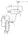
- FIG. 1 is a schematic view showing a flow sheet of a propylene polymerization reactor in which a horizontal reaction tank and a stirring fluidized bed reaction tank are combined in the present invention.
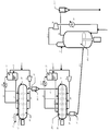
- FIG. 2 is a schematic view showing a flow sheet of a propylene polymerization reactor in which a horizontal reaction tank and a vertical stirring tank are combined in the present invention.
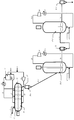
- FIG. 3 is a schematic diagram showing a flow sheet of a propylene polymerization reactor in which a horizontal reaction vessel and a fluidized bed reaction vessel are combined in the present invention.
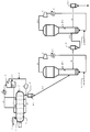
- FIG. 4 is a schematic diagram showing a process flow of a preferred embodiment when a horizontal reaction vessel and a fluidized bed reaction vessel are combined in the present invention, and a flow sheet of the production method used in the examples.
- FIG. 5 is a schematic diagram showing a flow sheet of a propylene polymerization reactor in which two horizontal reaction vessels and one stirred fluidized bed reaction vessel are combined in the present invention.
- FIG. 6 is a schematic view showing a flow sheet of a propylene polymerization reactor in which two horizontal reaction tanks and one (vertical) stirring tank are combined in the present invention.
- FIG. 7 is a schematic view showing a flow sheet of a propylene polymerization reactor in which two horizontal reaction tanks and one fluidized bed reaction tank are combined in the present invention.
- FIG. 8 is a schematic view showing a flow sheet of a propylene polymerization reaction apparatus in which two horizontal reaction tanks and one fluidized bed reaction tank are combined in the present invention, and a flow sheet of a production method used in the examples.
- FIG. 9 is a schematic diagram showing a flow sheet of a propylene polymerization reactor in which one horizontal reaction tank and two stirred fluidized beds are combined in the present invention.
- FIG. 10 is a schematic view showing a flow sheet of a propylene polymerization reactor in which one horizontal reaction tank and two vertical stirring tanks are combined in the present invention.
- FIG. 11 is a schematic view showing a flow sheet of a propylene polymerization reactor in which one horizontal reaction tank and two fluidized bed reaction tanks are combined in the present invention.
- FIG. 12 is a schematic diagram showing a flow sheet of a propylene polymerization reactor in which one horizontal reaction tank and two fluidized bed reaction tanks are combined in the present invention, and a flow sheet of a production method used in the examples.
- FIG. 13 is a schematic diagram showing a flow sheet of a propylene polymerization reactor in which a horizontal reaction tank and a stirring fluidized bed reaction tank are combined in the present invention.
- FIG. 14 is a schematic diagram showing a flow sheet of a propylene polymerization reactor in which a horizontal reaction tank and a vertical stirring tank are combined in the present invention.
- FIG. 15 is a schematic view showing a flow sheet of a propylene polymerization reactor in which a horizontal reaction vessel and a fluidized bed reaction vessel are combined in the present invention.
- FIG. 16 is a schematic view showing a process flow of a preferred embodiment when a horizontal reaction vessel and a fluidized bed reaction vessel are combined in the present invention, and a flow sheet of the production method used in the examples.
- the propylene polymerization reaction apparatus of the present invention is a reaction apparatus for producing a propylene-based polymer by a multistage continuous gas phase polymerization method, and has a horizontal reaction tank having a stirrer rotating around a horizontal axis therein, and the horizontal type At least one or more complete mixing tanks connected to the reaction tank are provided.
- the propylene polymerization reaction apparatus of the present invention is a reaction apparatus for producing a propylene polymer by a multistage continuous gas phase polymerization method, and has a horizontal type having a stirrer rotating around a horizontal axis in at least two tanks.
- the reaction tank and at least one complete mixing tank are all arranged in series.
- the propylene polymerization reaction apparatus of the present invention is a polymerization reaction apparatus for producing a propylene polymer by a multistage continuous gas phase polymerization method, and has a stirrer rotating around a horizontal axis in at least one tank.
- a horizontal reaction tank and at least two complete mixing tanks are all arranged in series.
- the propylene polymerization reactor of the present invention is further provided with a receiver having a level meter between the horizontal reaction tank and the complete mixing tank, and controls the amount of polymer to be transferred between the two tanks. It is characterized by doing.
- the method for producing a propylene polymer of the present invention is a method for producing a propylene polymer using the propylene polymerization reactor, and performs multistage continuous gas phase polymerization of propylene in the presence of an olefin polymerization catalyst. It is characterized by that.
- embodiments of the present invention will be described in detail with reference to the drawings as necessary. Further, the positional relationship such as up, down, left and right is based on the positional relationship shown in the drawings unless otherwise specified. Further, the dimensional ratios in the drawings are not limited to the illustrated ratios.
- the propylene polymerization reaction apparatus of the present invention is a reaction apparatus for producing a propylene-based polymer by a multistage continuous gas phase polymerization method, and has a horizontal reaction tank having a stirrer rotating around a horizontal axis therein, and the horizontal type At least one or more complete mixing tanks connected to the reaction tank are provided.
- the propylene polymerization reaction apparatus of the present invention is a reaction apparatus for producing a propylene polymer by a multistage continuous gas phase polymerization method, and has a horizontal type having a stirrer rotating around a horizontal axis in at least two tanks.
- the reaction tank and at least one complete mixing tank are all arranged in series.
- the propylene polymerization reaction apparatus of the present invention is a reaction apparatus for producing a propylene polymer by a multistage continuous gas phase polymerization method, and has a horizontal type having a stirrer rotating around a horizontal axis in at least one tank.
- the reaction tank and at least two complete mixing tanks are all arranged in series.
- the propylene polymerization reactor of the present invention is further provided with a receiver having a level meter between the horizontal reaction tank and the complete mixing tank, and controls the amount of polymer to be transferred between the two tanks. It is characterized by doing. Examples of the apparatus having the minimum reactor configuration of the present invention are shown in FIGS.
- a known reaction tank can be used as long as it is a horizontal reaction tank having a stirrer rotating around a horizontal axis.
- a horizontal reaction tank as shown in FIGS. 1 to 16 can be used.
- the horizontal reaction tanks shown in FIGS. 1 to 16 may be the same. 1 to 16, horizontal reaction tanks 10 and 20-1 having a stirrer rotating around a horizontal axis are used in at least one tank, and are elongated and have upstream ends 12 and 22 and downstream ends 14 and 24. As shown in 1 to 16, it is generally installed in a horizontal position. As shown in FIGS.
- the stirring shaft extends into the downstream end 14 of the reaction tank 10, and a blade for stirring is attached in the reaction tank 10.
- the stirring blade mixes the polymer particles with other substances introduced into it in the reaction vessel 10.
- the catalyst components introduced from the upstream pipes 1 and 2 of the reaction tank 10 start polymerization while being mixed with the polymer particles by the stirring blade.
- the polymerization heat generated during the polymerization is removed by the latent heat of evaporation of the raw material liquefied propylene supplied from the top pipe 17. Unreacted propylene gas is discharged out of the reaction system through the pipe 13, part of which is condensed in the condenser 15, and separated into a liquid phase and a gas phase in the gas-liquid separation tank 11.
- the liquid phase part is introduced into the pipe 17 for removing the polymerization heat, and the gas phase part is mixed with hydrogen or the like for molecular weight adjustment and supplied via the pipe 18 installed at the bottom of the reaction vessel 10.
- a horizontal reaction vessel 10 or 20-1 having a stirrer rotating around a horizontal axis is elongated and has an upstream end 12 or 22 and a downstream end 14 or 24. As shown in FIG. It is installed at.
- the stirring shaft extends into the reaction vessel 10 or 20-1, and a blade for stirring is attached.
- the stirring blade mixes the polymer particles with other substances introduced into the reaction vessel 10 or 20-1.
- the horizontal reaction tank 10 and the horizontal reaction tank 20-1 are arranged in this order from the upstream of the process.
- the catalyst components introduced from the upstream pipes 1 and 2 of the reaction tank 10 start polymerization while being mixed with the polymer particles by the stirring blade.
- the polymerization heat generated during the polymerization is removed by the latent heat of evaporation of the raw material liquefied propylene supplied from the top pipe 17. Unreacted propylene gas is discharged out of the reaction system through the pipe 13, part of which is condensed in the condenser 15, and separated into a liquid phase and a gas phase in the gas-liquid separation tank 11.
- the liquid phase part is introduced into the pipe 17 for removal of polymerization heat, and the gas phase part is mixed with hydrogen or the like for molecular weight adjustment and supplied via the pipe 18 installed at the bottom of the reaction vessel 10.
- the reaction product in the horizontal reaction tank 10 is upstream of the reactor of the horizontal reaction tank 20-1 from the polymer supply pipe 41-1. It is supplied to the vicinity of the end 22.
- the polymer supplied to the polymerization vessel 20-1 is continuously polymerized while being mixed by a stirring blade.
- the polymerization heat generated during the polymerization is removed by the latent heat of evaporation of the raw material liquefied propylene supplied from the top pipe 27-1.
- Unreacted propylene gas is discharged out of the reaction system through the pipe 23, part of it is condensed in the condenser 25-2, and separated into a liquid phase and a gas phase in the gas-liquid separation tank 21.
- the liquid phase part is introduced into the pipe 27-1 for removing the heat of polymerization, and the gas phase part is mixed with hydrogen, ethylene or the like as necessary, and passes through the pipe 28 arranged at the bottom of the reaction tank 20-1. Supplied.
- the horizontal reaction tank which is an essential polymerization tank in the present invention is greatly different from the other reaction tanks.
- the catalyst component is added to the upstream part of the reaction tank and grows as powder particles by polymerization, It is in the point of moving downstream. Therefore, the horizontal reaction tank has a narrower residence time distribution compared to the reaction tank of the complete mixing tank type, and the concentration of particles with a relatively short residence time (short path particles) present near the reaction tank outlet is extremely low. Become. Therefore, in the present invention aiming at gel reduction and prevention of adhesion in the reaction tank, it is essential to carry out in a horizontal reaction tank.
- At least one horizontal reaction tank is disposed.
- the horizontal reaction tank is preferably installed before the complete mixing tank which is an essential element of the present invention.
- Short path particles flowing into the complete mixing tank are reduced by installing a horizontal reaction tank, and the amount of electron donating compounds added for the purpose of suppressing gel in the complete mixing tank and preventing adhesion in the reaction tank is reduced. Is possible.
- the electron donating compound has an action of deactivating the polymerization active site of the catalyst, excessive addition significantly reduces the catalytic activity after the second reaction tank (reaction tank following the tank to which the electron donating compound has been added). It is difficult to secure the amount of reaction to be performed.
- the horizontal reaction tank has a feature that the residence time distribution is narrower than other reaction tanks, and the effect desired by the present invention can be sufficiently achieved with one tank, but the number of reaction tanks is further increased. Thus, the effect can be further enhanced.
- At least two horizontal reaction vessels can be arranged in series.
- the residence time distribution can be further narrowed, and the concentration of short path particles can be further reduced.
- the hydrogen concentration in the second horizontal reaction tank lower than the hydrogen concentration in the first horizontal reaction tank, hydrogen leakage into the subsequent reaction tank can be reduced. A high molecular weight copolymer component is easily produced.
- reaction vessel having the same shape as the reaction tank described above for the second and subsequent tanks.
- the size of the reaction vessel is not particularly limited, but it is desirable to use a reaction vessel having the same volume as that of the previous reaction vessel or a larger volume.
- a reaction tank having a volume smaller than that of the previous reaction tank is used, the residence time in the tank is extremely short, which is disadvantageous in terms of suppressing short pass particles.
- the L / D of the horizontal reaction tank in the present invention is preferably 3 or more, more preferably 5 or more, and preferably 10 or less.
- L is the length of the reaction tank in the horizontal longitudinal direction
- D is the inner diameter of the reaction tank.
- the “complete mixing tank” in the present invention means a reaction tank characterized in that when a substance in the tank flows in and out, the concentration in the tank is equal to the concentration of the effluent flow. That is, the complete mixing tank is advantageous in terms of the uniformity of the quality of the substance produced in the reaction tank because the temperature in the tank and the composition of the reaction gas are uniform.
- a complete mixing tank constituting the propylene polymer production apparatus of the present invention a known reaction tank can be used as long as it is a complete mixing tank as described above. Examples of the complete mixing tank widely used as a propylene polymerization apparatus include a vertical stirring tank, a stirring fluidized bed reaction tank, and a fluidized bed reaction tank.
- FIGS. 1-16 a complete mixing vessel as shown in FIGS. 1-16 can be used.
- FIG. 1 shows an example in which a stirred fluidized bed reaction tank is used as a complete mixing tank, a vertical stirring tank is used in FIG. 2, and a fluidized bed reaction tank is used in FIG.
- the complete mixing tanks shown in FIGS. 1 to 16 may be the same.
- the polymerization heat is removed mainly by the latent heat of vaporization of the raw material liquefied propylene (for example, a horizontal reaction tank), and the removal method is mainly performed by sensible heat of the circulating gas in the reaction tank.
- the complete mixing tank used in the present invention is characterized in that the polymerization heat is mainly removed by sensible heat of the circulating gas.
- a reaction vessel is preferred.
- reaction gas (reaction zone gas) and the circulation gas (circulation zone gas) in the continuous multistage gas phase polymerization method using the complete mixing tank of the propylene-based polymer include propylene and ethylene which are the aforementioned raw materials. ⁇ -olefin, hydrogen, and other raw materials.
- the process of mainly removing the heat of polymerization caused by the circulating gas includes a stirring fluidized bed reaction vessel and a fluidized bed reaction vessel.
- the fluidized bed reaction vessel is used for the reaction gas uniformity and copolymer particles. It is more desirable from the viewpoint of uniform stirring.
- the number of the reaction vessels is not particularly limited, but it is preferable to have at least one reaction vessel that removes the heat of polymerization caused by the circulating gas.
- the residence time is controlled, the polymer is uniformly dispersed, the reaction gas is uniform,
- the use of a fluidized bed reactor is more desirable from the viewpoint of uniform stirring of the coalesced particles.
- the reaction tank uses the sensible heat of the circulating gas to remove the heat of polymerization, and thus is not affected by productivity due to a decrease in the dew point of the reaction gas.
- the method of removing the polymerization heat is a method in which the evaporation latent heat of the raw material liquefied propylene is used
- propylene / ⁇ -olefin (for example, ethylene) gas is supplied from the bottom of the reaction tank, and the raw material liquefied propylene is supplied from the upper part of the reaction tank. Therefore, the gas composition is likely to be non-uniform in the reaction vessel, so that the composition distribution and molecular weight distribution of ⁇ -olefin copolymerized around the polymer particles are generated.
- a component having a low ⁇ -olefin content or a component having a low molecular weight is present in the copolymer, which lowers the low temperature impact resistance of the final product.
- the gloss of the final product is increased.
- At least two tanks of this complete mixing tank can be arranged in series.
- two or more complete mixing tanks it becomes easy not only to increase the content of the copolymer component of the propylene-based block copolymer, but also when producing copolymer components in two or more tanks, By using copolymer components having different ⁇ -olefin contents and / or molecular weights, further improvement and diversity of quality can be achieved.
- FIG. 4 shows a flow diagram of an apparatus using a fluidized bed reaction tank.
- the fluidized bed reaction tank 20-2 is elongated in the vertical direction, and the polymer produced in the preceding step is supplied from the pipe 34.
- the polymer in the fluidized bed reaction tank 20-2 is fluidized with the raw material propylene and other raw material gases such as hydrogen and ethylene supplied to the reaction tank at a linear velocity equal to or higher than the minimum fluidization rate, and the polymerization reaction is performed. Done.
- the unreacted mixed gas is extracted out of the reaction system through an unreacted gas extraction pipe 23, cooled by a circulating gas cooler 25-1, and supplied to the reaction tank 20-2 as a circulating gas (fluidizing gas).
- the polymer produced in the reaction tank 20-2 is transferred to the next step via the pipe 33-1 and the receiver (degas tank) 31.
- FIG. 12 shows a flow chart of an apparatus using fluidized bed reaction tanks as two complete mixing tanks.
- the first fluidized bed reaction tank 20-2 is elongated in the vertical direction, and the polymer produced in the preceding step is supplied from the pipe 25-3.
- the polymer in the fluidized bed reaction tank 20-2 is fluidized with the raw material propylene and other raw material gases such as hydrogen and ethylene supplied to the reaction tank at a linear velocity equal to or higher than the minimum fluidization rate, and the polymerization reaction is performed. Done.
- the unreacted mixed gas is extracted out of the reaction system through an unreacted gas extraction pipe 23, cooled by a circulating gas cooler 25-1, and supplied to the reaction tank 20-2 as a circulating gas (fluidizing gas).
- the polymer produced in the reaction tank 20-2 is transferred to the next step via the pipe 38 and the receiver (degas tank) 31.
- the polymer particles withdrawn from the reaction tank 20-2 are supplied to the second fluidized bed reaction tank 40-2 through the pipe 27-2.
- the fluidized bed reaction vessel 40-2 is elongated in the vertical direction, and the polymer produced in the previous step is supplied to the reaction vessel at a linear velocity higher than the minimum fluidization rate, and other raw materials such as propylene and hydrogen and ethylene.
- the polymerization reaction is performed by fluidizing with gas.
- the unreacted mixed gas is extracted out of the reaction system through an unreacted gas extraction pipe 33-2, cooled by a circulating gas cooler 45, and supplied to the reaction tank 40-2 as a circulating gas (fluidizing gas).
- the polymer produced in the reaction tank 40-2 is transferred to the next step via the pipe 39 and the receiver (degas tank) 32-2.
- ⁇ Receiver with level meter> when transferring a polymer between reaction tanks, you may install and use a receiver (degassing tank) between these reaction tanks. Thereby, the amount of entrained gas can be reduced and the amount of the polymer remaining in the pipe can be reduced.
- a receiver having a level meter is installed and used between the reaction tanks.
- the receiver 30-2 is arranged directly below the horizontal reaction tank and at a position higher than the inlet of the next reaction tank polymer.
- the level meter installed in the receiver 30-2 measures the amount of the polymer in the receiver 30-2, and examples thereof include a ⁇ -ray level meter and an admittance level meter.
- the receiver 30-2 is provided with a polymer extraction pipe 32-1 from the horizontal reaction tank, a polymer supply pipe 34 to the next reaction tank, a pressurized gas supply pipe 41-2, and a gas discharge pipe 42-2.
- a polymer discharge valve W and a polymer transfer valve X are attached to the pipe, and preferably a gas introduction valve Y and a gas discharge valve Z are further attached.
- the flow of a molecular weight regulator such as hydrogen to the next process is blocked as much as possible, and the reaction gas composition fluctuation in the next process reaction tank is reduced.
- a molecular weight regulator such as hydrogen
- Placing the receiver directly below the horizontal reactor outlet and higher than the fluidized bed reactor inlet minimizes the amount of entrained gas and minimizes the amount of polymer remaining in the piping. It is effective for.
- installing a level meter in the receiver to control the discharge of the polymer is effective in preventing an excessive pressurized gas from flowing into the next process.
- the polymer discharge valve W is opened, and a predetermined amount of polymer is intermittently introduced into the receiver 30-2.
- the gas entrained with the polymer in the receiver 30-2 is discharged to a gas recovery system (not shown) by opening the gas discharge valve Z, and the pressure of the receiver 30-2 becomes a predetermined value.
- the gas discharge valve Z is closed.
- the pressurized gas introduction valve Y is opened, the pressurized gas is introduced into the receiver 30-2 from the pipe 41-2, and then the valve Y is closed.
- the polymer transfer valve X is opened, and the polymer in the receiver 30-2 and the transfer pipe 34 is transferred to the next process by the pressurized gas.
- the polymer transfer valve X is closed after the amount of the polymer falls below the set amount.
- One cycle of the polymer transfer operation is completed.
- a series of treatments is automatically performed by a series of sequence operations of each shut-off valve.
- ⁇ Device configuration> With regard to providing high productivity of the continuous multistage gas phase polymerization method according to the present invention, there is no limitation on the order of installation as long as it is an apparatus in which a horizontal reaction tank and a complete mixing tank are connected. With respect to the order of installation, either a horizontal reaction tank-complete mixing tank or a complete mixing tank-horizontal reaction tank can be used. In the present invention, at least one apparatus in which a horizontal reaction tank and a complete mixing tank are connected is required in a series of manufacturing steps, and another apparatus may be arranged before and after this apparatus.
- one or a plurality of additional polymerization reaction tanks such as a horizontal reaction tank or a reaction tank that mainly uses sensible heat of the circulating gas are provided in the front stage or the rear stage to realize an apparatus comprising three or more reaction tanks.
- the configuration of such an apparatus includes a horizontal reaction tank-a horizontal reaction tank-a complete mixing tank, a horizontal reaction tank-a complete mixing tank-a complete mixing tank, a horizontal reaction tank-a horizontal reaction tank-a complete mixing tank-a complete mixing tank, etc. Can be mentioned.
- the apparatus in order to reduce the amount of non-standard product generated when changing the residence time in the reaction tank using the sensible heat of the circulating gas, it is preferable to dispose the complete mixing tank immediately after the horizontal reaction tank.
- the apparatus preferably includes a configuration in which the complete mixing tank is disposed immediately after the horizontal reaction tank.
- the reaction amount can be controlled in each stage of the polymerization process.
- a small amount of a polymerization deactivator is supplied to control the reaction amount.
- the use of an excessive polymerization quencher greatly reduces the reaction amount in the next step. End up. Therefore, in order to control the reaction amount in the continuous multistage gas phase polymerization method, it may be necessary to change the propylene partial pressure or the residence time in the reaction tank depending on the use of the polymerization deactivator.
- a fluidized bed reaction tank that is a complete mixing tank is used.
- polymer particles that have received a history with a wide residence time distribution are supplied to the fluidized bed reaction tank.
- the particle size distribution of the polymer particles is wide.
- the amount of circulating gas should be such that small particles of polymer do not scatter outside the system. It is necessary to carry out gradually while adjusting, resulting in a large amount of non-standard products.
- the present invention is an apparatus that exhibits the highest effect when producing a polymer having a low molecular weight polypropylene component or a high concentration ethylene component in the polymer component.
- a component with a high molecular weight is produced in a horizontal reaction tank, and a component with a low molecular weight is subsequently produced in a complete mixing tank, which is a reaction tank that mainly uses sensible heat of circulating gas.
- a complete mixing tank which is a reaction tank that mainly uses sensible heat of circulating gas.
- copolymers having greatly different ethylene contents in each polymerization step can be suitably produced.
- it is suitable for the production of a propylene-based block copolymer, and examples of the copolymer include a propylene-propylene / ethylene block copolymer, a propylene / ethylene-propylene / ethylene block copolymer, and the like.
- the copolymer include a propylene-propylene / ethylene block copolymer, a propylene / ethylene-propylene / ethylene block copolymer, and the like.
- the homopolypropylene component is produced in a horizontal reaction tank, and then propylene / ethylene copolymer is mainly used in a complete mixing tank, which is a reaction tank that mainly uses sensible heat of the circulating gas.
- a complete mixing tank which is a reaction tank that mainly uses sensible heat of the circulating gas.
- the multi-stage continuous gas phase polymerization method may be an apparatus in which two or more horizontal reaction tanks and one or more complete mixing tanks are connected. There are no restrictions. Preferably, two or more of the horizontal reaction tanks are disposed in front of the complete mixing tank disposed upstream of the process.
- the configuration of such an apparatus is as follows. From the upstream of the process, horizontal reaction tank-horizontal reaction tank-complete mixing tank, horizontal reaction tank-horizontal reaction tank-complete mixing tank-horizontal reaction tank, horizontal reaction tank-horizontal reaction tank- Examples include a complete mixing tank—a complete mixing tank, a horizontal reaction tank—a horizontal reaction tank—a horizontal reaction tank—a horizontal reaction tank—a complete mixing tank.
- At least two horizontal reaction vessels can be arranged in series.
- the residence time distribution can be further narrowed, and the concentration of short path particles can be further reduced.
- the hydrogen concentration in the second horizontal reaction tank lower than the hydrogen concentration in the first horizontal reaction tank, hydrogen leakage into the subsequent reaction tank can be reduced.
- High molecular weight copolymer components are easily produced. In particular, it is preferable to arrange them in the order of horizontal reaction tank-horizontal reaction tank-complete mixing tank.
- an inexpensive and quality stable polymer of the multistage continuous gas phase polymerization method it may be performed in an apparatus in which one or more horizontal reaction tanks and two or more complete mixing tanks are connected,
- the installation order is as follows: horizontal reaction tank-complete mixing tank-complete mixing tank, horizontal reaction tank-horizontal reaction tank-complete mixing tank-complete mixing tank, horizontal reaction tank-vertical reaction tank-vertical reaction tank- Any configuration such as a horizontal reaction vessel can be used.
- one in which one or more horizontal reaction tanks are arranged in front of the complete mixing tank arranged upstream of the process can be used.
- At least two complete mixing tanks can be arranged in series.
- two or more complete mixing tanks it becomes easy not only to increase the content of the copolymer component of the propylene-based block copolymer, but also when producing copolymer components in two or more tanks,
- copolymer components having different ⁇ -olefin contents and / or molecular weights By using copolymer components having different ⁇ -olefin contents and / or molecular weights, further improvement in quality and diversity can be achieved.
- the propylene-based block polymer which is suitable for automobile members, home appliance members, and the like and has an excellent balance of rigidity / impact resistance and in addition the generation of gel is suppressed, is prevented from adhering in the reaction vessel and is stable. Can be manufactured efficiently.
- it since it is a continuous gas phase polymerization method, it is possible to supply a cheaper and more stable propylene-based block copolymer.
- a receiver may be installed between the reaction tanks.
- a receiver degassing tank
- a receiver may be installed between the reaction phases and used.
- the amount of entrained gas can be reduced and the amount of the polymer remaining in the pipe can be reduced.
- a receiver provided with a level meter is preferable.
- a series of processing is automatically performed by a series of sequence operations of each shut-off valve.
- reaction tank other than the horizontal reaction tank and the complete mixing tank, and other equipment those usually used in a polymerization reaction apparatus for a propylene polymer can be used.
- the method for producing a propylene polymer of the present invention is characterized in that multistage continuous gas phase polymerization of propylene is performed in the presence of an olefin polymerization catalyst using the above-described propylene polymerization reactor.
- the type of the olefin polymerization catalyst used in the present invention is not particularly limited, and a known catalyst can be used.
- a so-called Ziegler-Natta catalyst in which a titanium compound and organoaluminum are combined for example, Japanese Patent Laid-Open Nos.
- the Ziegler-Natta catalyst is a titanium trichloride or titanium trichloride composition obtained by reduction with an organoaluminum as a titanium compound and treated with an electron donating compound (for example, JP-A-47-34478, JP-A-58-23806, JP-A-63-146906), a so-called supported catalyst obtained by supporting titanium tetrachloride on a carrier such as magnesium chloride (for example, JP-A-58-157808, JP-A-58-58). 83006, Japanese Patent Laid-Open No. 58-5310, Japanese Patent Laid-Open No. 61-218606), and the like. As these catalysts, known catalysts can be used without any particular limitation.
- an organoaluminum compound can be used as a promoter.
- the organoaluminum compound include trialkylaluminum such as trimethylaluminum, triethylaluminum and triisobutylaluminum, alkylaluminum halide such as diethylaluminum chloride and diisobutylaluminum chloride, alkylaluminum hydride such as diethylaluminum hydride, diethylaluminum ethoxide and the like.
- Alkyl aluminum alkoxides such as methylalumoxane and tetrabutylalumoxane, and complex organoaluminum compounds such as dibutyl methylboronate and lithium aluminum tetraethyl. It is also possible to use a mixture of two or more of these.
- organosilicon compounds such as diphenyldimethoxysilane and tert-butylmethyldimethoxysilane, esters such as ethyl acetate, butyl benzoate, methyl p-toluate, and dibutylphthalate, ketones such as acetone and methyl isobutyl ketone, diethyl ether And electron donating compounds such as ethers such as benzoic acid and propionic acid, and alcohols such as ethanol and butanol.
- organosilicon compounds such as diphenyldimethoxysilane and tert-butylmethyldimethoxysilane, esters such as ethyl acetate, butyl benzoate, methyl p-toluate, and dibutylphthalate, ketones such as acetone and methyl isobutyl ketone, diethyl ether And electron donating compounds such as ethers such as benzoic acid and propionic acid, and alcohols
- the olefin polymerization catalyst in the present invention is preferably used after prepolymerization before being used in the main polymerization. Prior to the main polymerization, a small amount of polymer is generated around the catalyst in advance by pre-polymerization treatment, so that the catalyst becomes more uniform and the generation amount of fine powder can be suppressed.
- the prepolymerization treatment can be carried out in the presence of an organoaluminum compound similar to the organoaluminum compound used for the main polymerization.
- the amount of the organoaluminum compound to be used varies depending on the kind of the polymerization catalyst component to be used, but usually the organoaluminum compound is preferably 0.1 to 40 mol, more preferably 0.3 to 0.3 mol per 1 mol of the titanium atom. It is used in the range of 20 mol.
- the temperature during the prepolymerization treatment is preferably ⁇ 150 ° C. to 150 ° C., more preferably 0 ° C. to 80 ° C.
- the prepolymerization treatment time is preferably 10 minutes to 48 hours.
- the pre-polymerization treatment amount is preferably such that 0.1 to 100 grams, more preferably 0.5 to 50 grams of an ⁇ -olefin monomer can be polymerized per gram of the olefin polymerization catalyst component.
- the prepolymerization treatment is usually performed in an inert solvent.
- an electron donor similar to the electron donor (also referred to as an electron donating compound) used in the main polymerization can be used as necessary.
- the electron donor is an organosilicon compound, it may be used in an amount of 0.01 to 10 moles per mole of the organoaluminum compound.
- compounds disclosed in JP-A No. 2004-124090 can be used as the monomer used for the prepolymerization treatment of the olefin polymerization catalyst.
- specific compounds include ethylene, propylene, 1-butene, 3-methylbutene-1, 4-methylpentene-1, 1-pentene, 1-hexene, 1-octene, 1-decene, 1-dodecene, Olefins represented by 1-tetradecene, 1-hexadecene, 1-octadecene, 1-eicocene, 4-methyl-1-pentene, 3-methyl-1-pentene, styrene, ⁇ -methylstyrene, allylbenzene, chloro Styrene-like compounds typified by styrene and the like, and 1,3-butadiene, isoprene, 1,3-pentadiene, 1,5-hexadiene, 2,6-octadiene, dicyclopenta
- ethylene, propylene, 3-methylbutene-1, 4-methylpentene-1, styrene, divinylbenzenes and the like are particularly preferable. These may be used alone or as a mixture of two or more with other ⁇ -olefins.
- a molecular regulator such as hydrogen can be used in combination.
- the prepolymerization treatment is generally preferably carried out with stirring, and an inert solvent can also be present at that time.
- Inert solvents used for pre-polymerization of olefin polymerization catalysts are notable for polymerization reactions such as liquid saturated hydrocarbons such as hexane, heptane, octane, decane, dodecane, and liquid paraffin, and silicon oil having a dimethylpolysiloxane structure. It is an inert solvent that has no effect.
- These inert solvents may be either one kind of single solvent or two or more kinds of mixed solvents. When these inert solvents are used, it is preferable to use them after removing impurities such as moisture and sulfur compounds which adversely affect the polymerization.
- the prepolymerization treatment may be performed a plurality of times, and the monomers used at this time may be the same or different. Further, the olefin polymerization catalyst after the prepolymerization treatment can be washed with an inert solvent such as hexane or heptane. The olefin polymerization catalyst after completion of the prepolymerization treatment can be used as it is, depending on the use form of the catalyst, but may be dried if necessary.
- a polymer such as polyethylene, polypropylene and polystyrene or an inorganic oxide solid such as silica and titania may coexist at the time of contacting or after contacting the olefin polymerization catalyst with each of the above components. Is possible.
- the method for producing a propylene polymer of the present invention is characterized in that multistage continuous gas phase polymerization of propylene is performed in the presence of an olefin polymerization catalyst using the above-described propylene polymerization reactor.
- the method for producing a propylene-based polymer of the present invention is a continuous multistage production method of propylene, which is obtained by polymerizing propylene (homopolymerization, copolymerization) to produce polypropylene, that is, a polypropylene polymer (propylene homopolymer, propylene). / ⁇ -olefin copolymer).
- ⁇ -olefins other than propylene used in the present invention include ethylene, 1-butene, 1-pentene, 4-methyl-1-pentene, 5-methyl-1-hexene, 1-hexene, 1-heptene, 1-heptene, For example, octene.
- the ⁇ -olefin to be used may be changed in each polymerization step, and two or more ⁇ -olefins may be used.
- propylene is polymerized (homopolymerization, copolymerization) in a horizontal reaction vessel to produce polypropylene, that is, a propylene-based polymer (including propylene homopolymer and propylene / ⁇ -olefin copolymer).
- ⁇ -olefins other than propylene used in the present invention include ethylene, 1-butene, 1-pentene, 4-methyl-1-pentene, 5-methyl-1-hexene, 1-hexene, 1-heptene, 1-heptene, For example, octene.
- Polymerization conditions such as temperature and pressure in the horizontal reaction tank can be arbitrarily set as long as productivity is not hindered in order to obtain a desired index (such as MFR and ethylene content).
- the polymerization temperature is preferably 0 ° C. or higher, more preferably 30 ° C. or higher, particularly preferably 40 ° C. or higher, while preferably 100 ° C. or lower, more preferably 90 ° C. or lower, particularly preferably 80 ° C.
- the polymerization pressure is at least atmospheric pressure, preferably at least 600 kPa, more preferably at least 1000 kPa, particularly preferably at least 1600 kPa.
- the polymerization pressure should not be set higher than the vapor pressure of propylene at the polymerization temperature.
- the residence time can be arbitrarily adjusted according to the composition of the polymerization reaction tank and the product index. Generally, it is set within the range of 30 minutes to 10 hours.
- propylene is polymerized (homopolymerization, copolymerization) in a complete mixing tank to produce polypropylene, that is, a propylene-based polymer (including propylene homopolymer and propylene / ⁇ -olefin copolymer).
- ⁇ -olefins other than propylene used in the present invention include ethylene, 1-butene, 1-pentene, 4-methyl-1-pentene, 5-methyl-1-hexene, 1-hexene, 1-heptene, 1-heptene, For example, octene.
- the “complete mixing tank” in the present invention is preferably a reaction tank characterized by removing polymerization heat mainly by sensible heat of the circulating gas.
- a reaction tank characterized by removing polymerization heat mainly by sensible heat of the circulating gas.
- the reaction tanks that are widely used include a stirred fluidized bed and a fluidized bed reaction tank. In the present invention, it is more preferable to use a fluidized bed reaction tank in terms of control of residence time and uniform dispersion of the polymer. .
- the reaction tank uses the sensible heat of the circulating gas to remove the heat of polymerization, and thus is not affected by productivity due to a decrease in the dew point of the reaction gas. Therefore, in the production method of the present invention, the polymerization reaction in the complete mixing tank is preferably performed using a reaction gas having a dew point of 50 ° C. or less.
- the “reaction gas” is, as described above, propylene as raw materials, ⁇ -olefin containing ethylene, hydrogen, and other raw materials.
- Polymerization conditions such as temperature and pressure in the complete mixing tank can be arbitrarily set as long as the effects of the present invention are not impaired.
- the polymerization temperature is preferably 0 ° C or higher, more preferably 30 ° C or higher, particularly preferably 40 ° C or higher, while preferably 100 ° C or lower, more preferably. 90 ° C. or lower, particularly preferably 80 ° C. or lower.
- the polymerization pressure is at least atmospheric pressure, preferably at least 600 kPa, more preferably at least 1000 kPa, particularly preferably at least 1600 kPa.
- the polymerization pressure should not be set higher than the vapor pressure of propylene at the polymerization temperature.
- the residence time can be arbitrarily adjusted according to the composition of the polymerization reaction tank and the product index. Generally, it is set within the range of 30 minutes to 10 hours.
- the method for producing a propylene-based block copolymer of the present invention is characterized in that multistage continuous gas phase polymerization of propylene is performed in the presence of an olefin polymerization catalyst using the above-described propylene polymerization reactor.
- the polymerization process of the present invention comprises two stages of a first stage polymerization process and a second stage polymerization process, and more preferably, the first stage polymerization process and the second stage polymerization process are performed in this order (first stage polymerization process). Step ⁇ second stage polymerization step).
- the method for producing a propylene-based block copolymer in the present invention is a horizontal reaction tank having a stirrer that rotates around the horizontal axis inside at least one tank in the first stage polymerization process. Is a complete mixing tank of at least one tank, and the polymerization heat is removed mainly in a reaction tank using sensible heat of the circulating gas.
- the method for producing a propylene-based block copolymer of the present invention is preferably based on propylene by homopolymerizing propylene or copolymerizing propylene and ⁇ -olefin (excluding propylene) in a horizontal reaction vessel.
- the first stage polymerization step for producing the polymer component (A) having a monomer unit content of 95% by weight or more is carried out, and subsequently, propylene and ⁇ -olefin (excluding propylene) in a complete mixing tank And a second-stage polymerization step for producing a copolymer component (B) having a content of monomer units based on propylene of 95 to 5% by weight.
- the polymerization in the horizontal reaction vessel is preferably a first stage polymerization step, and the polymerization in the first stage polymerization step is carried out by using propylene alone or a mixture of propylene and ⁇ -olefin in a substantially gas phase state as a catalyst for olefin polymerization.
- Ethylene is common as the ⁇ -olefin.
- a propylene homopolymer or a propylene / ⁇ -olefin copolymer having an ⁇ -olefin content of 5% by weight or less is formed. If the ⁇ -olefin content in the propylene / ⁇ -olefin polymer obtained in the first stage polymerization step exceeds 5% by weight, the rigidity of the final copolymer may be lowered. Therefore, in the first stage polymerization step, it is preferable to produce a polymer component (A) in which the content of monomer units based on propylene is 95% by weight or more.
- Polymerization conditions such as temperature and pressure in the first stage polymerization step can be arbitrarily set as long as the effects of the present invention are not impaired.
- the polymerization temperature is preferably 0 ° C. or higher, more preferably 30 ° C. or higher, particularly preferably 40 ° C. or higher, while preferably 100 ° C. or lower, more preferably 90 ° C. or lower, particularly preferably 80 ° C.
- the polymerization pressure is at least atmospheric pressure, preferably at least 600 kPa, more preferably at least 1000 kPa, particularly preferably at least 1600 kPa.
- the polymerization pressure should not be set higher than the vapor pressure of propylene at the polymerization temperature.
- the residence time can be arbitrarily adjusted according to the composition of the polymerization tank and the product index. Generally, it is set within the range of 30 minutes to 10 hours.
- the melt flow rate (MFR) of the polymer can be controlled using a molecular weight regulator such as hydrogen.
- MFR in the first stage polymerization step is preferably 10 g / 10 minutes or more, more preferably 30 g / 10 minutes or more, and further preferably 50 g / It can be 10 minutes or more.
- the first stage polymerization step is preferably performed in one tank or two or more horizontal reaction tanks.
- the first stage polymerization step can be performed in two or more horizontal reaction vessels using two or more horizontal reaction vessels.
- the first stage polymerization step is performed in two horizontal reaction tanks, for the purpose of selectively and efficiently deactivating short path particles from the previous horizontal reaction tank, it is exemplified in JP-A No. 2002-265516.
- the electron donor to be used may be added to two tanks as necessary.
- MFR disparity can be provided between the reaction tanks.
- the amount of hydrogen entrained cannot be ignored.
- a high concentration of hydrogen is inevitably required in the first stage polymerization step, and accordingly, the amount of hydrogen entrained in the second stage polymerization step increases.
- the hydrogen concentration in the second stage polymerization process can be kept low by setting the hydrogen concentration in the subsequent horizontal reaction tank low. Become.
- the first stage polymerization step is preferably performed in one or two or more horizontal reaction tanks. More preferably, the first stage polymerization step is carried out in two or more horizontal reaction vessels. By performing the first stage polymerization step in a horizontal reactor having two or more tanks, the gel can be further reduced. On the other hand, when the first stage polymerization step is carried out in one horizontal reaction tank, a part of the copolymerization of propylene and other ⁇ -olefin, which is the second stage polymerization process, in the remaining one or more horizontal reaction tanks. Will be performed.
- the ⁇ -olefin content in the copolymer component in the horizontal reaction vessel is preferably 30% by weight or less, more preferably 25% by weight or less, It is preferably 20% by weight or less, particularly preferably 15% by weight or less.
- the polymerization in the complete mixing tank is preferably a second-stage polymerization step, and a rubbery polymer (polymer component (B)) is prepared by polymerizing a mixture of propylene and ⁇ -olefin in one or more complete mixing tanks. ).
- a rubbery polymer polymer component (B))
- B rubbery polymer
- ethylene is preferable.
- a copolymer component in which the content of monomer units based on propylene is 95 to 5% by weight
- ⁇ -olefin excluding propylene. It is preferred to produce B).
- An ⁇ -olefin copolymer can be produced. When the ⁇ -olefin content is 5% by weight or less, the low temperature impact resistance of the propylene block copolymer is lowered. When the ⁇ -olefin is excessive, the gel is increased or the tensile properties of the propylene block copolymer are lowered. May be incurred.
- the polymerization amount in this step is 10% by weight or more of the total polymerization amount, preferably 15% by weight or more of the total polymerization amount, more preferably 20% by weight or more, and further preferably 25% by weight or more, Preferably it is 90 weight% or less, More preferably, it is 70 weight% or less, More preferably, it is 50 weight% or less. If the rubbery polymer is too small, sufficient impact strength cannot be obtained, and if it is too large, the powder fluidity of the propylene-based block copolymer may be significantly deteriorated and adhesion to the system may occur. is there.
- another comonomer of ethylene may coexist.
- the comonomer for example, ⁇ -olefin such as 1-butene, 1-pentene, 1-hexene, 4-methyl-1-pentene can be used.
- Polymerization conditions such as temperature and pressure in the second stage polymerization step can be arbitrarily set as long as the effects of the present invention are not impaired.
- the polymerization temperature is preferably 0 ° C. or higher, more preferably 30 ° C. or higher, particularly preferably 40 ° C. or higher, while preferably 100 ° C. or lower, more preferably 90 ° C. or lower, particularly preferably 80 ° C. It is as follows.
- the polymerization pressure is preferably at least atmospheric pressure, more preferably at least 600 kPa, particularly preferably at least 1000 kPa, even more preferably at least 1600 kPa, while it is preferably at most 4200 kPa, more preferably at most 3500 kPa, particularly preferably at most 3000 kPa. it can.
- the polymerization pressure should not be set lower than the vapor pressure of propylene at the polymerization temperature.
- the residence time can be arbitrarily adjusted according to the composition of the polymerization tank and the product index. Generally, it is set within the range of 30 minutes to 10 hours.
- the molecular weight modifier may or may not be used depending on the purpose, but the hydrogen concentration targeted by the reaction tank of the second stage polymerization step is due to hydrogen leakage from the previous reaction tank. If it can be maintained, it may not be used again.
- an electron donor exemplified in JP-A No. 2002-265516 is added for the purpose of selectively and efficiently deactivating the short path particles from the first step polymerization tank as necessary. Also good.
- the second stage polymerization step is preferably performed in two or more complete mixing tanks.
- the second stage polymerization step can be performed using two or more complete mixing tanks using two or more complete mixing tanks.
- the ⁇ -olefin content and the molecular weight of the copolymer can be different in each complete mixing tank.
- the second stage polymerization step is composed of two or more complete mixing tanks.
- the first stage polymerization process is performed in the preceding complete mixing tank and a horizontal reaction tank connected thereto.
- it is difficult to make the ⁇ -olefin content and molecular weight different in the second stage polymerization step but it is possible to make a difference in the molecular weight of the polymer produced in each reactor in the first stage polymerization step. It becomes possible, or by setting the hydrogen concentration in the complete mixing tank in the previous stage low, entrainment of hydrogen etc. in the second stage polymerization process can be reduced, and the molecular weight of the propylene / ⁇ -olefin copolymer can be reduced. It becomes easy to raise.
- the transfer of the polymer from the horizontal reaction tank to the reaction tank for removing the polymerization heat mainly by sensible heat of the circulating gas is preferably a transfer of the polymer from the first stage polymerization process to the second stage polymerization process. It is implemented in a receiver with a meter.
- the transfer process by the receiver is as follows: a) a step of intermittently extracting the polymer from the first stage polymerization step into the receiver; b) removing the gas introduced with the polymer from the receiver; c) step of boosting the receiver again with propylene gas or inert gas; d) It preferably comprises a step of introducing the polymer in the receiver into the second stage polymerization step.
- the amount of the polymer extracted in one intermittent extraction operation is desirably 50% by volume or more of the capacity of the receiver, more preferably 60% by volume or more and 90% by volume or less, more preferably 80% by volume or less. If the amount to be extracted is too small, the amount of gas entrained increases, and if it is too large, a part of the polymer extracted in step b) may also enter the discharge system and cause troubles such as blockage. There is. Since the extraction of the polymer involves the leakage of the gas component in the first stage polymerization step, the leakage gas is discharged from the receiver by dropping the pressure after the receiver is disconnected from the first stage polymerization step ( Step b).
- the drop pressure is preferably 0.5 MPa or less, more preferably 0.2 MPa or less.
- the receiver containing the polymer is pressurized with gas.
- gas used for pressurization
- an inert gas which does not become a catalyst poison for example, nitrogen, a saturated hydrocarbon having 1 to 4 carbon atoms, propylene, or a mixture thereof can be used.
- a gas used for pressurization that is preferably used is propylene single gas.
- the pressure increase is higher than the polymerization pressure in the second stage polymerization step, preferably 0.2 MPa or more.
- the receiver is pressurized to a predetermined value and then communicated with the second stage polymerization process, and the polymer is transferred to the second stage polymerization process.
- the amount of polymer attenuation in the receiver is monitored by a level meter installed in the receiver, and simultaneously with the completion of the discharge of the polymer, the receiver and the second stage polymerization process are shut off.
- Using an excess amount of pressurizing gas to completely discharge from the receiver is a useful method to prevent residual in the transfer piping, but using excess pressurized gas is a second-stage polymerization.
- the receiver is arranged at a position higher than the inlet of the second stage polymerization step reaction vessel, thereby suppressing the residence in the pipe as much as possible and using an inert gas or a single propylene gas as the pressurized gas.
- production of an adhesion component can be suppressed.
- This series of sequences (step a ⁇ step d) is within 15 minutes, preferably within 10 minutes, more preferably 3 minutes. It is desirable to be implemented within. When a series of sequences takes 15 minutes or more, there is a possibility that clogging with the polymer staying in the transfer pipe may occur.
- a plurality of the receivers installed between the horizontal reaction tank (first stage polymerization process) and the complete mixing tank (second stage polymerization process) may be installed as long as the above conditions are satisfied.
- propylene is polymerized (homopolymerization, copolymerization), and polypropylene, that is, a propylene-based polymer (including propylene homopolymer and propylene / ⁇ -olefin copolymer). Is manufactured.
- the apparatus and production method of the present invention exhibit the highest effect when producing a polymer component having a low molecular weight polypropylene component or a high concentration ethylene component in the polymer component.
- a component with a high molecular weight is produced in a horizontal reaction tank, and a component with a low molecular weight is subsequently produced in a complete mixing tank, which is a reaction tank that mainly uses sensible heat of the circulating gas.
- a complete mixing tank which is a reaction tank that mainly uses sensible heat of the circulating gas.
- High productivity can be obtained by manufacturing, and when a fluidized bed reaction vessel is used as a complete mixing vessel, the generation of non-standard products can be minimized when the conditions are changed.
- the intrinsic viscosity of the polymer component produced in the polymerization process using the horizontal reaction vessel for producing the polymer component having the highest molecular weight is 5 to 100 dl / g.
- the intrinsic viscosity is more than 5 times the intrinsic viscosity of the polymer component produced in the polymerization process using the complete mixing tank for producing the polymer component having the lowest molecular weight, and the polymer component having the highest molecular weight is produced.
- Examples thereof include propylene-based polymers in which the amount of the polymer component produced in the polymerization step using the horizontal reaction tank is 0.1 to 80% by weight in the propylene-based polymer.
- a propylene / ethylene copolymer, a propylene / ethylene / 1-butene copolymer, and the like can be suitably produced as copolymers having greatly different ethylene contents in each polymerization step.
- it is suitable for the production of a propylene-based block copolymer, and examples of the copolymer include a propylene-propylene / ethylene block copolymer, a propylene / ethylene-propylene / ethylene block copolymer, and the like.
- the copolymer include a propylene-propylene / ethylene block copolymer, a propylene / ethylene-propylene / ethylene block copolymer, and the like.
- the homopolypropylene component is produced in a horizontal reaction tank, and the propylene / ethylene copolymer component is subsequently added in a complete mixing tank that is a reaction tank that mainly uses sensible heat of the circulating gas.
- a complete mixing tank that is a reaction tank that mainly uses sensible heat of the circulating gas.
- the propylene-based block copolymer produced by the “propylene polymerization reactor equipped with at least two horizontal reactors” according to the third to fifth inventions of the present invention and the sixth to eighth inventions of the present invention
- the propylene-based block copolymer produced by the “propylene polymerization reactor equipped with at least two completely mixed layers”, which is the invention is co-polymerized with the melt flow rate (MFR 1 ) of the polymer component (A).
- MFR 1 melt flow rate of the coalesced component
- MFR 2 melt flow rate of the coalesced component
- the propylene block copolymer produced by the “propylene polymerization reactor equipped with at least two completely mixed layers” according to the sixth to eighth inventions of the present invention has rigidity / impact resistance.
- a qualitatively stable propylene-based block copolymer having such characteristics can be supplied at a lower cost.
- an apparatus and a manufacturing method capable of stably producing a continuous multistage polymer at a low cost and with high productivity, and greatly reducing the amount of non-standard products generated by changing the polymerization conditions. can do.
- the substitution property of the polymer in a multistage polymerization reaction apparatus is high, and the product loss accompanying the change of the manufacturing conditions in continuous polymerization is reduced.
- the propylene polymer obtained by the apparatus and the production method of the present invention is excellent in the uniformity of the polymer structure between the propylene polymer particles, and is suitably used for automobile parts, home appliance parts, packaging materials and the like.
- the propylene-based block copolymer has an excellent balance of rigidity / impact resistance and can efficiently produce a propylene-based block polymer in which generation of gel and gloss are suppressed.
- a qualitatively stable propylene-based block copolymer having the above-described characteristics can be supplied at a lower cost.
- the propylene-based block copolymer obtained by the present invention has the properties of excellent balance of rigidity / impact resistance, less generation of gel, and suppression of gloss. It is used in the molding field and is particularly suitable for automotive materials.
- the propylene-based block copolymer produced by “a propylene polymerization reactor equipped with at least two horizontal reactors” has an excellent balance of rigidity / low-temperature impact resistance and is free from gel generation. It has the characteristic of few. Therefore, it is used in the fields of injection molding and extrusion molding, and is particularly suitable for automobile materials.
- a propylene-based block copolymer produced by a “propylene polymerization reactor equipped with at least two completely mixed layers” has an excellent balance of rigidity / impact resistance and generates less gel. Therefore, it is used in the fields of injection molding and extrusion molding, and is particularly suitable for materials for automobiles, household appliances, and the like.
- Example 1 uses the apparatus shown in FIG. 4
- Example 2 uses the apparatus shown in FIG. 8
- Example 3 uses the apparatus shown in FIG. 12, and Examples 4, 5 and Comparative Example 10 was carried out using the apparatus shown in FIG. The measuring method of each physical property value in the present invention is shown below.
- Example 1 Preparation of Olefin Polymerization Catalyst (Solid Catalyst) Component A 10 L autoclave equipped with a stirrer was sufficiently substituted with nitrogen, and 2 L of purified toluene was introduced. To this, 200 g of Mg (OEt) 2 and 1 L of TiCl 4 were added at room temperature. The temperature was raised to 90 ° C. and 50 ml of n-butyl phthalate was introduced. Thereafter, the temperature was raised to 110 ° C. to carry out a reaction for 3 hours. The reaction product was thoroughly washed with purified toluene. Subsequently, the refined toluene was introduce
- Mg (OEt) 2 and 1 L of TiCl 4 200 g of Mg (OEt) 2 and 1 L of TiCl 4 were added at room temperature. The temperature was raised to 90 ° C. and 50 ml of n-butyl
- the reaction heat was removed by the heat of vaporization of the raw material liquefied propylene supplied from the pipe 3.
- the unreacted gas discharged from the polymerization vessel was cooled and condensed outside the reaction tank system through the pipe 13 and then refluxed to the polymerization vessel 10 through the pipe 17.
- the produced first-stage polymerization polymer is intermittently withdrawn from the polymerization vessel 10 through the pipe 32-1 so that the polymer retention level is 60% by volume of the reaction volume, and the second-stage polymerization step polymerization vessel 20 is obtained.
- a part of the polymer was taken out, and used as a sample for measuring MFR and measuring the polymer yield per unit weight of the catalyst.
- the MFR was 0.8 g / 10 min.
- the polymer yield per catalyst unit weight was calculated from the Mg content in the polymer measured by inductively coupled plasma emission spectrometry (ICP method). The Mg content was 13.1 ppm.
- Second-stage polymerization step Following the first-stage polymerization step, polymerization in the second-stage polymerization step was carried out in a fluidized bed reactor having an internal volume of 2000 liters. At a reaction temperature of 70 ° C., hydrogen as a molecular weight control agent was continuously supplied so that the molar ratio of hydrogen / propylene was 0.13 so that the pressure was 2.0 MPa. The dew point of the reaction gas was 46 ° C. The powder polymerized in the second reaction tank is made to flow so that the superficial velocity becomes 0.40 m / sec, and about 2 kg at a time so that the average amount of powder in the reaction tank is 30 kg.
- a part of the obtained polymer was used as a sample for measuring MFR and measuring the polymer yield per unit weight of the catalyst.
- the MFR was 4.9 g / 10 minutes.
- the polymer yield per unit catalyst weight was calculated by dividing the production rate by the solid catalyst feed rate. The results are shown in Table 1.
- Example 2 1) Preparation of Olefin Polymerization Catalyst (Solid Catalyst) A solid catalyst component was prepared according to Example 1. 2) Prepolymerization treatment of olefin polymerization catalyst (solid catalyst) A 20 L autoclave equipped with a stirrer was sufficiently substituted with nitrogen, and 100 g of a solid catalyst component was introduced. 50 ml of silicon tetrachloride was added and the reaction was carried out at 90 ° C. for 1 hour, and then the reaction product was thoroughly washed with purified n-heptane.
- n-heptane was introduced to adjust the liquid level to 4 L, 30 ml of dimethyldivinylsilane, 30 ml of diisopropyldimethoxysilane, and 80 g of triethylaluminum were added, and a reaction was carried out at 40 ° C. for 2 hours. The reaction product was thoroughly washed with purified n-heptane. Again, purified n-heptane was introduced to adjust the concentration of the solid catalyst component to 20 g / L. After the slurry was cooled to 10 ° C., 10 g of triethylaluminum was added, and 280 g of propylene was supplied over 4 hours.
- the powder polymerized in the first reaction tank is made to flow so that the superficial velocity becomes 0.35 m / sec, and about 2 kg at a time so that the average amount of powder in the reaction tank is 30 kg.
- propylene and hydrogen as a molecular weight controlling agent were continuously supplied so that the molar ratio of hydrogen / propylene was 0.13 so that the polymerization temperature was 70 degrees and the pressure was 2.0 MPa. .
- the dew point of the reaction gas was 46 ° C.
- the powder polymerized in the second reaction tank is made to flow so that the superficial velocity becomes 0.40 m / sec, and about 2 Kg at a time so that the average amount of powder in the reaction tank is 30 kg.
- the production rate of the propylene polymer was 20 kg on an average per hour.
- the MFR was 6.4 g / 10 minutes.
- the amount of powder held in the reaction vessel was increased from 30 kg to 60 kg while monitoring the fine particles not to be scattered in the circulation system, and the time required at this time was measured. It cost.
- Table 1 The results are shown in Table 1.
- Example 2 First-stage polymerization step This will be described with reference to the flow sheet shown in FIG.
- a (10) Continuously supplied to the most upstream part.
- the produced first-stage polymer is intermittently withdrawn from the reaction tank A (10) through the pipe 37 so that the polymer retention level is 60% by volume of the reaction volume, and the reaction tank B (20-1). Supplied to. At this time, a part of the polymer was intermittently collected from the pipe 41-1, and used as a sample for measuring the polymer yield per unit weight of MFR and catalyst. The polymer yield per catalyst unit weight was calculated from the Mg content in the polymer measured by inductively coupled plasma emission spectrometry (ICP method).
- ICP method inductively coupled plasma emission spectrometry
- the powder discharged from the reaction tank A (10) was received from the upstream part of the horizontal reaction tank B (20-1) having a stirring blade. While maintaining the conditions of a reaction temperature of 70 ° C., a reaction pressure of 2.1 MPa, and a stirring speed of 35 rpm, hydrogen gas was maintained so that the hydrogen concentration in the gas phase in the reaction vessel was maintained at the hydrogen / propylene molar ratio shown in Table 1.
- the reaction heat was removed by the heat of vaporization of the raw material liquefied propylene supplied from the pipe 27-1.
- the unreacted gas discharged from the reaction tank was cooled and condensed outside the reaction tank system through the pipe 23 and refluxed to the reaction tank 20-1 through the pipe 27-1.
- the polymer produced in the reaction vessel B is intermittently withdrawn from the reaction vessel B (20-1) through the pipe 38 so that the retained level of the polymer is 60% by volume of the reaction volume. It was supplied to the tank C (40-1). At this time, a part of the polymer was intermittently collected from the pipe 42-1 and used as a sample for measuring the polymer yield per unit weight of MFR and catalyst.
- the polymer yield per catalyst unit weight was calculated from the Mg content in the polymer measured by inductively coupled plasma emission spectrometry (ICP method).
- Second-stage polymerization step Following the first-stage polymerization step, polymerization in the second-stage polymerization step was carried out in a fluidized bed reactor having an internal volume of 2000 liters. This fluidized bed reaction tank is connected in series immediately after the second reaction tank in the first stage polymerization step. Propylene and ethylene were continuously supplied at a reaction temperature of 60 ° C. and a pressure of 2.0 MPa so that the molar ratio of ethylene / propylene was 0.33.
- propylene block copolymers were measured for MFR, ethylene content by infrared absorption spectrum analysis, copolymer production by measurement of Mg content in the polymer by ICP method, various machines It was used for measurement of physical properties and gel.
- propylene block copolymer 4 g was added with 2.0 g of pentaerythryl-tetrakis [3- (3,5-t-butyl-4-hydroxyphenyl) propionate] as a phenolic antioxidant, -2.0 g of (2,4-di-t-butylphenyl) phosphite, 2.0 g of calcium stearate as a neutralizing agent, and 12 g of talc are added, and a high-speed stirring mixer (Henschel mixer) is used. The mixture was mixed at room temperature for 2 minutes, and the mixture was granulated using an extrusion granulator having a screw diameter of 40 mm.
- test piece was prepared from the granulated product using an injection molding machine at a molten resin temperature of 250 ° C. and a mold temperature of 50 ° C.
- the obtained test piece was conditioned for 72 hours in a room with a humidity of 50% and a room temperature of 23 ° C., and the mechanical properties were measured. The results are shown in Table 1.
- test piece was prepared from the granulated product using an injection molding machine at a molten resin temperature of 250 ° C. and a mold temperature of 50 ° C.
- the obtained test piece was conditioned for 72 hours in a room with a humidity of 50% and a room temperature of 23 ° C., and the mechanical properties were measured. The results are shown in Table 1.
- the produced polymer in the first stage polymerization step was intermittently withdrawn from the reaction vessel A (10) through the pipe 37 so that the polymer retention level was 60% by volume of the reaction volume. At this time, a part of the polymer was intermittently collected from the pipe 37 to prepare a sample for measuring the polymer yield per unit weight of MFR and catalyst.
- the polymer yield per catalyst unit weight was calculated from the Mg content in the polymer measured by inductively coupled plasma emission spectrometry (ICP method).
- the component polymerized in the first stage polymerization step was the polymer component (A).
- the powder polymerized in the fluidized bed reactor 20-2 is caused to flow so that the superficial velocity is 0.40 m / sec, and the amount of powder held in the reactor is 1 so that the average amount of powder is 40 kg.
- About 2 kg was intermittently extracted from the pipe 38 into the degassing tank 31 once every 5 to 10 minutes.
- a part of the polymer is intermittently collected from the pipe 38, measured for ethylene content by MFR and infrared absorption spectrum analysis, and measured per unit weight of the catalyst by measurement of Mg content in the polymer by ICP method. The combined yield was used for calculation.
- the component polymerized in this step was the polymer component (B1).
- the polymer discharged from the fluidized bed type reaction tank 20-2 was supplied to the fluidized bed type reaction tank 40-2 through the pipe 27-2, and the second stage polymerization step was subsequently carried out.
- Propylene and ethylene are continuously supplied at a reaction temperature of 60 ° C. and a pressure of 2.0 MPa so that the molar ratio of ethylene / propylene is 0.63.
- hydrogen as a molecular weight control agent is Hydrogen and ethylene are continuously supplied from the pipe 8 so that the molar ratio of ethylene / ethylene is 0.09, and at the same time, ethyl alcohol as an active hydrogen compound is 0.9 times the mole of triethylaluminum. Supplied from 8-2.
- the powder polymerized in the reaction vessel 40-2 is made to flow so that the superficial velocity is 0.40 m / sec, and about 2 kg at a time so that the average amount of powder in the reaction vessel is 60 kg. It was intermittently extracted from the pipe 39 into the degassing tank 32-2 once every 5 to 10 minutes.
- the component polymerized in this step was the polymer component (B2). Further, it was transferred to another vessel where nitrogen gas containing moisture was supplied to stop the reaction, and the residual gas was purged to obtain a propylene-based block copolymer.
- propylene block copolymers were measured for MFR, ethylene content by infrared absorption spectrum analysis, copolymer production by measurement of Mg content in the polymer by ICP method, various machines It was used for measurement of physical properties and gel.
- propylene block copolymer 4 g was added with 2.0 g of pentaerythryl-tetrakis [3- (3,5-t-butyl-4-hydroxyphenyl) propionate] as a phenolic antioxidant, -2.0 g of (2,4-di-t-butylphenyl) phosphite, 2.0 g of calcium stearate as a neutralizing agent, and 12 g of talc are added, and a high-speed stirring mixer (Henschel mixer) is used. The mixture was mixed at room temperature for 2 minutes, and the mixture was granulated using an extrusion granulator having a screw diameter of 40 mm.
- test piece was prepared from the granulated product using an injection molding machine at a molten resin temperature of 250 ° C. and a mold temperature of 50 ° C.
- the obtained test piece was conditioned for 72 hours in a room with a humidity of 50% and a room temperature of 23 ° C., and the mechanical properties were measured. The results are shown in Table 1.
- the solid catalyst subjected to the preactivation treatment (preliminary polymerization treatment) described in Comparative Example 2 was supplied so that the polymer polymerization rate was 12 kg / hour.
- the powder polymerized in the first reaction tank (crystalline propylene polymer) is caused to flow so that the superficial velocity is 0.35 m / sec, and the amount of powder held in the reaction tank is 30 kg on average.
- about 2 kg at a time was intermittently extracted into the vessel once every 5 to 10 minutes, and then transferred to the second reaction tank (first polymerization step).
- the component polymerized in the first stage polymerization step was the polymer component (A).
- the MFR was 135 g / 10 minutes.
- the polymer yield per catalyst unit weight was calculated from the Mg content in the polymer measured by inductively coupled plasma emission spectrometry (ICP method). The Mg content was 8.4 ppm.
- polymerization in the second stage polymerization step was performed in a fluidized bed reactor having an internal volume of 2000 liters.
- propylene and ethylene are continuously supplied at a polymerization temperature of 60 ° C. and a pressure of 2.0 MPa so that the molar ratio of ethylene / propylene is 0.32, and further, a molecular weight control agent.
- the powder polymerized in the second reaction tank is made to flow so that the superficial velocity becomes 0.40 m / sec, and about 2 Kg at a time so that the average amount of powder in the reaction tank is 30 kg. Intermittently extracted into the degassing tank once every 5 to 10 minutes, and then transferred to another vessel where nitrogen gas containing moisture was supplied to stop the reaction, purge the residual gas, A propylene block copolymer was obtained (second stage polymerization step).
- the component polymerized in the second stage polymerization step was the polymer component (B1).
- a part of the obtained propylene-based block copolymer was subjected to MFR measurement, ethylene content measurement by infrared absorption spectrum analysis, various mechanical properties and gel measurement.
- the MFR is 30 g / 10 min
- the polymerization ratio of the second stage polymer produced in the second stage polymerization step is 26% by weight based on the total amount of the obtained propylene-based block copolymer, and the second stage polymer.
- the polymerization ratio of ethylene therein was 38% by weight based on the polymer component (B1) polymerized in the second stage polymerization step.
- test piece was prepared from the granulated product using an injection molding machine at a molten resin temperature of 250 ° C. and a mold temperature of 50 ° C.
- the obtained test piece was conditioned for 72 hours in a room with a humidity of 50% and a room temperature of 23 ° C., and the mechanical properties were measured. The results are shown in Table 1.
- Propylene and ethylene are continuously supplied so that the molar ratio of ethylene / propylene is 0.32 at a polymerization temperature of 60 ° C. and a pressure of 2.0 MPa.
- hydrogen as a molecular weight control agent is In addition to continuously supplying 0.13 in the molar ratio of / ethylene, ethyl alcohol was supplied as an active hydrogen compound so that the molar ratio was 0.3 times that of triethylaluminum.
- the powder polymerized in the second reaction tank is withdrawn intermittently so that the retained level of the polymer is 60% by volume of the reaction volume, the nitrogen gas containing water is supplied to stop the reaction, and both propylene block A polymer was obtained (second stage polymerization step).
- the component polymerized in the second stage polymerization step was the polymer component (B1).
- a part of the obtained propylene-based block copolymer was subjected to measurement of MFR, measurement of ethylene content by infrared absorption spectrum analysis, measurement of various mechanical properties and gel.
- the MFR is 32 g / 10 minutes
- the polymerization ratio of the second stage polymer produced in the second stage polymerization step is 28% by weight based on the total amount of the obtained propylene-based block copolymer, and the second stage polymer.
- the polymerization ratio of ethylene therein was 37% by weight based on the polymer component (B1) polymerized in the second stage polymerization step.
- test piece was prepared from the granulated product using an injection molding machine at a molten resin temperature of 250 ° C. and a mold temperature of 50 ° C.
- the obtained test piece was conditioned for 72 hours in a room with a humidity of 50% and a room temperature of 23 ° C., and the mechanical properties were measured. The results are shown in Table 1.
- the reaction heat was removed by the vaporization heat of the raw material liquefied propylene supplied from the pipe 17.
- the unreacted gas discharged from the polymerization vessel was cooled and condensed outside the reaction tank system through the pipe 13 and then refluxed to the polymerization vessel 10 through the pipe 17.
- the produced first-stage polymerization polymer is intermittently withdrawn from the polymerization vessel 10 through the pipe 32-1 so that the polymer retention level is 60% by volume of the reaction volume, and the second-stage polymerization step polymerization vessel 20 is obtained. -2.
- the transfer of the polymer from the first stage polymerization process to the second stage polymerization process was performed based on the following valve sequence operation.
- the polymer yield per catalyst unit weight was calculated from the Mg content in the polymer measured by inductively coupled plasma emission spectrometry (ICP method).
- Second-stage polymerization step Following the first-stage polymerization step, polymerization in the second-stage polymerization step was carried out in a fluidized bed reactor having an internal volume of 2000 liters. Propylene and ethylene are continuously supplied at a reaction temperature of 60 ° C. and a pressure of 2.0 MPa so that the molar ratio of ethylene / propylene is 0.3. Further, hydrogen as a molecular weight control agent is In addition to continuously supplying 0.13 in the molar ratio of / ethylene, ethyl alcohol was supplied as an active hydrogen compound so that the molar ratio was 0.4 times that of triethylaluminum.
- the powder polymerized in the second reaction tank is made to flow so that the superficial velocity becomes 0.40 m / sec, and about 2 Kg at a time so that the average amount of powder in the reaction tank is 30 kg. Intermittently extracted into a vessel once every 5 to 10 minutes and transferred to another vessel where nitrogen gas containing moisture is supplied to stop the reaction, purge the residual gas, A polymer was obtained.
- propylene block copolymers were measured for MFR, ethylene content by infrared absorption spectrum analysis, copolymer production by measurement of Mg content in the polymer by ICP method, various machines It was used for measurement of physical properties and gel.
- the MFR was 34 g / 10 min
- the polymerization ratio of the second stage polymer produced in the second stage polymerization step was 27% by weight based on the total amount of the obtained propylene-based block copolymer, and the second stage polymer.
- the polymerization ratio of ethylene therein was 37% by weight based on the polymer polymerized in the second stage polymerization step.
- propylene block copolymer 4 g was added with 2.0 g of pentaerythryl-tetrakis [3- (3,5-t-butyl-4-hydroxyphenyl) propionate] as a phenolic antioxidant, -2.0 g of (2,4-di-t-butylphenyl) phosphite, 2.0 g of calcium stearate as a neutralizing agent, and 12 g of talc were added, and a high-speed stirring mixer (Henschel mixer) was The mixture was mixed at room temperature for 2 minutes, and the mixture was granulated using an extrusion granulator having a screw diameter of 40 mm.
- test piece was prepared from the granulated product using an injection molding machine at a molten resin temperature of 250 ° C. and a mold temperature of 50 ° C.
- the obtained test piece was conditioned for 72 hours in a room with a humidity of 50% and a room temperature of 23 ° C., and the mechanical properties were measured. The results are shown in Table 1.
- Example 5 When changing the hydrogen / propylene ratio in the first stage polymerization step, changing the hydrogen / ethylene ratio, ethylene / propylene ratio and ethanol / TEA ratio in the second stage polymerization step, and when granulating the propylene-based block copolymer This was carried out in accordance with Example 4 except that talc was removed. The results are shown in Table 1.
- hydrogen as a molecular weight control agent is In addition to continuously supplying 0.13 in the molar ratio of / ethylene, ethyl alcohol was supplied as an active hydrogen compound so that the molar ratio was 0.3 times that of triethylaluminum.
- the powder polymerized in the second reaction tank is withdrawn intermittently so that the retained level of the polymer is 60% by volume of the reaction volume, the nitrogen gas containing water is supplied to stop the reaction, and both propylene block A polymer was obtained (second stage polymerization step).
- propylene block copolymers were measured for MFR, ethylene content by infrared absorption spectrum analysis, copolymer production by measurement of Mg content in the polymer by ICP method, various machines It was used for measurement of physical properties and gel.
- the MFR is 32 g / 10 minutes
- the polymerization ratio of the second stage polymer produced in the second stage polymerization step is 28% by weight based on the total amount of the obtained propylene-based block copolymer, and the second stage polymer.
- the polymerization ratio of ethylene therein was 37% by weight based on the polymer polymerized in the second stage polymerization step.
- test piece was prepared from the granulated product using an injection molding machine at a molten resin temperature of 250 ° C. and a mold temperature of 50 ° C.
- the obtained test piece was conditioned for 72 hours in a room with a humidity of 50% and a room temperature of 23 ° C., and the mechanical properties were measured. The results are shown in Table 1.
- the powder polymerized in the first reaction tank (crystalline propylene polymer) is caused to flow so that the superficial velocity is 0.35 m / sec, and the amount of powder held in the reaction tank is 30 kg on average.
- about 2 kg at a time was intermittently extracted into the vessel once every 5 to 10 minutes, and then transferred to the second reaction tank (first polymerization step).
- the transfer of the polymer from the first stage polymerization process to the second stage polymerization process uses a level meter installed in the receiver (30), and the receiver (30) valve sequence operation described in Example 1 is performed. Based on.
- the MFR was 135 g / 10 minutes.
- polymerization in the second stage polymerization step was performed in a fluidized bed reactor having an internal volume of 2000 liters.
- propylene and ethylene are continuously supplied at a polymerization temperature of 60 ° C. and a pressure of 2.0 MPa so that the molar ratio of ethylene / propylene is 0.32, and further, a molecular weight control agent.
- a molecular weight control agent was continuously supplied so that the molar ratio of hydrogen / propylene was 0.10, and ethyl alcohol was supplied as an active hydrogen compound so that the molar ratio was 0.8 times that of triethylaluminum. .
- the powder polymerized in the second reaction tank is made to flow so that the superficial velocity becomes 0.40 m / sec, and about 2 Kg at a time so that the average amount of powder in the reaction tank is 30 kg.
- Some of the resulting propylene block copolymers were measured for MFR, ethylene content by infrared absorption spectrum analysis, copolymer production by measurement of Mg content in the polymer by ICP method, various machines It was used for measurement of physical properties and gel.
- the MFR is 30 g / 10 min
- the polymerization ratio of the second stage polymer produced in the second stage polymerization step is 26% by weight based on the total amount of the obtained propylene-based block copolymer, and the second stage polymer.
- the polymerization ratio of ethylene therein was 38% by weight based on the polymer polymerized in the second stage polymerization step.
- test piece was prepared from the granulated product using an injection molding machine at a molten resin temperature of 250 ° C. and a mold temperature of 50 ° C.
- the obtained test piece was conditioned for 72 hours in a room with a humidity of 50% and a room temperature of 23 ° C., and the mechanical properties were measured. The results are shown in Table 1.
- Example 10 (Comparative Example 10) According to Example 4 except that the level meter operation is not used in the valve (B) operation sequence of the receiver (30), and the valve is closed when the pressure of the receiver (30) reaches 2.1 MPa. Carried out.
- the propylene polymerization reaction apparatus and the propylene-based polymer production method of the present invention are “a horizontal reaction tank having a stirrer rotating around a horizontal axis therein, and a connection to the horizontal reaction tank.
- Comparative Examples 1 and 2 which are methods that do not satisfy the requirement that at least one or more complete mixing tanks are provided, the production rate is significantly reduced under conditions where the dew point of the reaction gas is below 50 ° C. (Comparative Example 1) Or, it takes a lot of time to change the polymerization conditions (Comparative Example 2).
- Example 1 in a method for producing a propylene multi-stage continuous gas phase polymer containing a polymerization component that requires a reaction gas condition having a low dew point, a horizontal reaction tank and a complete mixing tank, which are specific matters of the present invention, are combined.
- a horizontal reaction tank and a complete mixing tank which are specific matters of the present invention.
- it is excellent in that it is very easy to adjust (short time) when changing the polymerization conditions (residence time). It was confirmed that a result was obtained.
- a specific matter of the production method of the present invention is “a horizontal reaction tank having a stirrer rotating around a horizontal axis in at least two tanks or more and complete mixing of at least one tank or more.
- Comparative Example 3 which is a method that does not satisfy the requirement of producing a propylene / ⁇ -olefin copolymer component in a tank-type reaction tank, is a propylene-based block copolymer with a large amount of gel generation. It can be seen that the polypropylene block copolymer composition of Example 2 produced by the production method of the present invention is a propylene block copolymer in which the generation of gel is suppressed.
- the hydrogen concentration in the second horizontal reaction tank by controlling the hydrogen concentration in the second horizontal reaction tank, the hydrogen concentration in the second stage polymerization process can be further reduced, and the molecular weight of the copolymer component can be further increased.
- the polypropylene block copolymer composition according to the example of the production method of the present invention also satisfies the value of MFR of 25 g / 10 min or more, which is a target for maintaining fluidity.
- a horizontal reaction tank having a stirrer rotating around a horizontal axis in at least one tank and at least two complete mixing tanks is a specific matter of the production method of the present invention.
- Comparative Examples 4 and 5 which are methods that do not satisfy the requirement that the propylene / ⁇ -olefin copolymer component is produced in a propylene polymerization reactor in which all are arranged in series.
- the polypropylene block copolymer composition of Example 3 according to the production method of the present invention has a high copolymer content and is contained in the copolymer component as compared with the propylene block copolymer having a large amount of generation.
- this is a propylene-based block copolymer in which the generation of gel is suppressed despite the high ethylene content.
- the polypropylene-based block copolymer composition according to the example is a propylene-based block copolymer in which the generation of gloss and gel is suppressed.
- the gloss is suppressed by setting the second stage polymerization step to a “complete mixing tank type reaction tank”.
- the first stage polymerization step is set to “a horizontal reaction tank having a stirrer that rotates about a horizontal axis inside”, thereby suppressing the generation of gel.
- Example 4 and Comparative Example 10 at least one horizontal reaction tank having a stirrer rotating around a horizontal axis and a complete mixing tank connected to the horizontal reaction tank are provided.
- the propylene / ⁇ -olefin copolymer component is produced by the “equipment apparatus”, but when the polymer is transferred from the first stage polymerization process to the second stage polymerization process, a level meter is not used and the receiver is used.
- a sequence operation is performed with a change in pressure. In this case, it can be seen that the disturbance (variation) of the reaction gas composition in the second stage polymerization step increases, and as a result, the gloss of the propylene-based block copolymer increases.
- the gloss of the specific matters of the present invention is to use the polymerization apparatus, to define the process in each polymerization step, and to use the polymer transfer method disclosed in the present invention. It was confirmed that excellent results were obtained in terms of suppression of gel generation.
- the apparatus and the production method of the present invention it is possible to produce a continuous multistage polymer of propylene-based polymer at a minimum equipment investment cost and stably maintain high productivity.
- the phase polymerization method when the residence time is changed in a specific gas phase polymerization reaction tank, the adjustment becomes extremely easy (short time), and as a result, the amount of non-standard products generated by changing the polymerization conditions is greatly reduced. Can be manufactured.
- a propylene-based block copolymer in which the generation of gel is suppressed can be obtained, an injection molded article having excellent appearance and rigidity / low temperature impact resistance can be obtained. Is possible.
- a propylene-based block polymer that is suitable for an automobile member, a household appliance member, and the like, has an excellent balance of rigidity / impact resistance, and additionally suppresses the generation of gel, Adhesion in the tank is suppressed, and stable and efficient production can be achieved.
- it is a continuous gas phase polymerization method it is possible to supply a cheaper and more stable propylene-based block copolymer.
Landscapes
- Chemical & Material Sciences (AREA)
- Organic Chemistry (AREA)
- Chemical Kinetics & Catalysis (AREA)
- Engineering & Computer Science (AREA)
- Combustion & Propulsion (AREA)
- Health & Medical Sciences (AREA)
- Medicinal Chemistry (AREA)
- Polymers & Plastics (AREA)
- Graft Or Block Polymers (AREA)
- Polymerisation Methods In General (AREA)
- Addition Polymer Or Copolymer, Post-Treatments, Or Chemical Modifications (AREA)
Abstract
Description
より詳しくは、多段連続気相重合法において、生産性を低下させることなく、重合条件変更に伴う規格外製品の発生量を大幅に低減でき、剛性/耐衝撃強度のバランスに優れ、加えてゲルの発生が抑制されるとともに、光沢が抑制されたもの、流動性が高いもの、反応槽内の付着が抑制されたより広い組成ものといった高い品質の連続多段重合体を、安定的かつ効率よく製造するプロピレン重合反応装置及びプロピレン系重合体の製造方法に関するものである。
しかしながら、ポリプロピレン単体ではその用途も限られることより、さまざまな改良が加えられてきた。例えば、耐衝撃性を向上させるため最初にホモポリプロピレンを重合し、その後プロピレンとエチレンの共重合を実施したプロピレン系ブロック共重合体、あるいは成形性・外観を改良するために分子量の異なるポリプロピレンを段階的に製造して分子量分布を拡大したプロピレン系重合体などが提案されている。
一般に、結晶性プロピレン成分の分子量を調整するために、水素などの分子量調整剤が使用されるが、特に本発明が所望するプロピレン系ブロック共重合体の高い流動性を発現させるためには、第1段重合工程における重合反応器内を高い水素濃度に維持し、更に共重合工程においては低い水素濃度を維持する必要がある。
更に完全混合槽での3段重合法におけるゲルの抑制や反応槽内の付着等の低減を目的とした別の方法としては、2槽目、3槽目に添加する電子供与性化合物の量を規定する方法(例えば、特許文献10参照)が提案されている。しかしながらこの方法では、第2反応器に比較的多量の電子供与化合物を添加する必要があり、添加する電子供与化合物の量によっては、各反応器で製造できる共重合体の反応量に制約が生じる。
より詳しくは、多段連続気相重合法において、生産性を低下させることなく、重合条件変更に伴う規格外製品の発生量を大幅に低減でき、剛性/耐衝撃強度のバランスに優れ、加えてゲルの発生が抑制されるとともに、光沢が抑制されたもの、流動性が高いもの、反応槽内の付着が抑制されたより広い組成ものといった高い品質の連続多段重合体を、安定的かつ効率よく製造するプロピレン重合反応装置及びプロピレン系重合体の製造方法を提供することにある。
第1段重合工程が、少なくとも2槽の前記横型反応槽にて行われることを特徴とするプロピレン系ブロック共重合体の製造方法が提供される。
第2段重合工程は、少なくとも2槽の前記完全混合槽にて行われることを特徴とするプロピレン系ブロック共重合体の製造方法が提供される。
また、本発明の第2の発明によれば、多段連続気相重合法において、特定の気相重合反応槽にて滞留時間の変更を行なう場合、その調整が極めて容易(短時間)となり、結果として重合条件変更に伴う規格外製品の発生量を大幅に低減して製造することができる製造装置であるという効果がある。
また、完全混合槽を2槽以上設置することで、プロピレン系ブロック共重合体の共重合体成分の含有量を高め易くなるばかりでなく、2槽以上で共重合体成分を製造する場合、各槽で異なるα-オレフィン含有量及び/又は分子量の共重合体成分とすることで、更なる品質の向上・多様性が図れる製造装置であるという効果がある。
また、完全混合槽を2槽以上設置することで、プロピレン系ブロック共重合体の共重合体成分の含有量を高め易くなるばかりでなく、2槽以上で共重合体成分を製造する場合、各槽で異なるα-オレフィン含有量及び/又は分子量の共重合体成分とすることで、更なる品質の向上・多様性が図れる製造方法であるという効果がある。
また、本発明のプロピレン重合反応装置は、プロピレン系重合体を多段連続気相重合法で製造するための反応装置であって、少なくとも2槽の内部に水平軸回りに回転する撹拌機を有する横型反応槽と、少なくとも1槽の完全混合槽とを、すべて直列に配置してなることを特徴とする。
また、本発明のプロピレン重合反応装置は、プロピレン系重合体を多段連続気相重合法で製造するための重合反応装置であって、少なくとも1槽の内部に水平軸回りに回転する撹拌機を有する横型反応槽と、少なくとも2槽の完全混合槽とを、すべて直列に配置してなることを特徴とする。
また、本発明のプロピレン重合反応装置は、さらに、前記横型反応槽と前記完全混合槽との間に、レベル計を有する受器が設けられ、両槽間を移送すべき重合体の量を制御することを特徴とする。
また、本発明のプロピレン系重合体の製造方法は、前記プロピレン重合反応装置を用いたプロピレン系重合体の製造方法であって、オレフィン重合用触媒の存在下にプロピレンの多段連続気相重合を行なうことを特徴とする。
以下、必要に応じて図面を参照しつつ、本発明の実施形態について詳細に説明する。また、上下左右等の位置関係は、特に断らない限り、図面に示す位置関係に基づくものとする。更に、図面の寸法比率は図示の比率に限られるものではない。
本発明のプロピレン重合反応装置は、プロピレン系重合体を多段連続気相重合法で製造するための反応装置であって、内部に水平軸回りに回転する撹拌機を有する横型反応槽と、該横型反応槽に連結する完全混合槽とが、それぞれ少なくとも1槽以上具備されていることを特徴とする。
また、本発明のプロピレン重合反応装置は、プロピレン系重合体を多段連続気相重合法で製造するための反応装置であって、少なくとも2槽の内部に水平軸回りに回転する撹拌機を有する横型反応槽と、少なくとも1槽の完全混合槽とを、すべて直列に配置してなることを特徴とする。
また、本発明のプロピレン重合反応装置は、プロピレン系重合体を多段連続気相重合法で製造するための反応装置であって、少なくとも1槽の内部に水平軸回りに回転する撹拌機を有する横型反応槽と、少なくとも2槽の完全混合槽とを、すべて直列に配置してなることを特徴とする。
また、本発明のプロピレン重合反応装置は、さらに、前記横型反応槽と前記完全混合槽との間に、レベル計を有する受器が設けられ、両槽間を移送すべき重合体の量を制御することを特徴とする。
本発明の最小の反応槽の構成での装置の例を図1から図14に示す。
本発明のプロピレン重合反応装置を構成する横型反応槽としては、内部に水平軸回りに回転する撹拌機を有する横型反応槽であれば公知の反応槽を使用することができる。一例として、図1~16に示したような横型反応槽を使用することができる。図1~16に示した横型反応槽は、それぞれ同じものであってもよい。
図1~16において、少なくとも1槽用いられる、内部に水平軸回りに回転する撹拌機を有する横型反応槽10、20-1は細長く、上流端12、22と下流端14、24を持ち、図1~16に示すように、一般的には水平位置で設置されている。
図1~4に示すように、攪拌軸は反応槽10の下流端14の中へ延び、攪拌の為の翼が反応槽10内で取り付けられている。攪拌翼はポリマー粒子を反応槽10内でその中へ導入される他物質と混合する。
反応槽10の上流部配管1および2より導入された触媒成分は、攪拌翼にてポリマー粒子と混合されながら、重合を開始する。重合の際、発生する重合熱は、頂部配管17から供給される原料液化プロピレンの蒸発潜熱により除去される。未反応のプロピレンガスは配管13にて反応系外へ出され、凝縮器15にてその一部分が凝縮され、気液分離槽11で液相と気相へ分離される。液相部は重合熱除去のため配管17へ導入され、気相部は分子量調節のための水素等と混合され、反応槽10の底部に設置された配管18を経由して供給される。
図5~8においては、プロセス上流より、横型反応槽10-横型反応槽20-1の順で配置されている。
反応槽10の上流部配管1および2より導入された触媒成分は、攪拌翼にてポリマー粒子と混合されながら、重合を開始する。重合の際、発生する重合熱は、頂部配管17から供給される原料液化プロピレンの蒸発潜熱により除去される。未反応のプロピレンガスは配管13にて反応系外へ出され、凝縮器15にてその一部分が凝縮され、気液分離槽11で液相と気相へ分離される。液相部は重合熱除去のため配管17へ導入され、気相部は、分子量調節のための水素等と混合され、反応槽10底部に設置された配管18を経由して供給される。
そのため横型反応槽は、完全混合槽型の反応槽に比べ、滞留時間分布が狭く、特に反応槽出口付近に存在する比較的滞留時間の短い粒子(ショートパス粒子)の濃度は非常に少ないものとなる。よって、ゲルの低減を及び反応槽内の付着防止を目的としている本発明においては、横型反応槽にて実施することが必須となる。
本発明における「完全混合槽」とは、槽内にある物質が流入し、そして流出される場合、槽内の濃度と流出流れの濃度が等しいことを特徴とする反応槽を意味する。すなわち、完全混合槽は、槽内の温度や反応ガスの組成などが均一であるため、反応槽内で製造される物質の品質の均一性という点で有利である。
本発明のプロピレン系重合体の製造装置を構成する完全混合槽としては、上述のような完全混合槽であれば、公知の反応槽を使用することができる。プロピレンの重合装置として広く利用されている完全混合槽としては、縦型撹拌槽、攪拌式流動床反応槽、流動床反応槽が挙げられる。一例として、図1~16に示したような完全混合槽を使用することができる。図1では完全混合槽として撹拌式流動床反応槽を、図2では縦型撹拌槽を、図3では流動床反応槽を使用した例を示す。図1~16に示した完全混合槽は、それぞれ同じものであってもよい。
このような重合環境が必要な部分での最適な重合反応槽として、主として循環ガスの顕熱を利用する反応槽を用いる。広く利用されている該反応槽としては、攪拌式流動床反応槽や流動床反応槽があるが、本発明においては滞留時間の制御、重合体の均一な分散、反応ガスの均一性および共重合体粒子の均一攪拌という観点から流動床反応槽の利用がより望ましい。該反応槽は、重合熱の除去のために循環ガスの顕熱を利用するので、反応ガスの露点低下による生産性への影響は受けない。
加えて、原料液化プロピレンの蒸発潜熱を重合熱の除去に利用するプロセスでは、必然的に反応ガス中のプロピレン濃度が高くなるため、共重合体成分(後で説明する成分(B))中のα-オレフィン含量を高め難い欠点があるが、主として循環ガスの顕熱より熱の除去を行うプロセスでは、その制約がなく、光沢の抑制又は耐低温衝撃性の付与という点では優れている。
反応槽20-2にて製造された重合体は配管33-1及び受器(脱ガス槽)31を経由して、次工程へ移送される。
第1の流動床反応槽20-2は縦に細長く、前段の工程で製造された重合体は、配管25-3より供給される。流動床反応槽20-2内の重合体は、該反応槽へ最小流動化速度以上の線速度で供給される原料プロピレンおよび水素やエチレンなどの他の原料ガスにて流動化され、重合反応が行われる。未反応の混合ガスは、未反応ガス抜き出し配管23より反応系外へ抜き出され、循環ガスクーラー25-1にて冷却され、循環ガス(流動化用ガス)として反応槽20-2へ供給される。
反応槽20-2にて製造された重合体は配管38及び受器(脱ガス槽)31を経由して、次工程へ移送される。
反応槽40-2にて製造された重合体は配管39及び受器(脱ガス槽)32-2を経由して、次工程へ移送される。
本発明において、反応槽間で重合体を移送する際に、受器(脱ガス槽)を該反応槽間に設置し、使用しても良い。これにより、同伴するガス量を少なくし、かつ、配管内に残留する重合体の量を少なくすることができる。
好ましくは横型反応槽から完全混合槽へ重合体を移送する際に、レベル計を有する受器が該反応槽間に設置され、使用される。本発明の一例として、図13~16を用いて説明すると、受器30-2は横型反応槽の直下、かつ次反応槽重合体入り口より高い位置に配列されている。受器30-2に設置されるレベル計は、受器30-2内の重合体の量を測定するものであり、γ線式レベル計やアドミッタンス式レベル計などが例示できる。
受器30-2には、横型反応槽からの重合体抜き出し配管32-1、次反応槽への重合体供給配管34、加圧ガス供給配管41-2、ガス排出配管42-2が取り付けられ、そられ配管には重合体排出弁W、重合体移送弁Xが取り付けられ、好ましくは、さらに、ガス導入弁Y、ガス排出弁Zが取り付けられる。
本発明による連続多段気相重合法の高い生産性の提供に関しては、横型反応槽及び完全混合槽が連結した装置であれば良く、設置順序に制約はない。設置順序については、横型反応槽-完全混合槽、完全混合槽-横型反応槽のどちらでも行なうことができる。また、本発明においては、一連の製造工程の中に、横型反応槽及び完全混合槽が連結した装置が少なくとも1つあればよく、この装置の前後に別の装置を配置しても良い。具体的には、横型反応槽や主として循環ガスの顕熱を利用する反応槽のような追加の重合反応槽を、前段または後段に1又は複数設け、3槽以上の反応槽からなる装置を実現してもよい。そのような装置の構成としては、横型反応槽-横型反応槽-完全混合槽、横型反応槽-完全混合槽-完全混合槽、横型反応槽-横型反応槽-完全混合槽-完全混合槽などが挙げられる。
連続多段気相重合法の場合、各段の重合工程でその反応量を制御することができる。一般には、ある重合工程の反応量を抑制したい場合は、少量の重合失活剤を供給して反応量を制御するが、過剰の重合失活剤の使用は次工程の反応量を大きく低下させてしまう。よって、連続多段気相重合法における反応量の制御は、重合失活剤の使用に応じて、プロピレン分圧の変更や反応槽内での滞留時間の変更をする必要が生じることがある。
例えば、分子量分布を拡大したホモポリプロピレンを製造する場合、横型反応槽で分子量の高い成分を製造し、引き続き、主として循環ガスの顕熱を利用する反応槽である完全混合槽にて分子量の低い成分を製造することにより、高い生産性が得られ、更に完全混合槽として流動床反応槽を用いた場合は、条件変更における規格外製品の発生を最小限に止めることができる。
プロピレン-プロピレン/エチレンブロック共重合体の製造の場合、ホモポリプロピレン成分を横型反応槽で製造し、引き続き、主として循環ガスの顕熱を利用する反応槽である完全混合槽にてプロピレン/エチレン共重合体成分を製造することにより、高い生産性が得られ、更に完全混合槽として流動床反応槽を用いた場合は、条件変更における規格外製品の発生を最小限に止めることができる。
特に、横型反応槽-横型反応槽-完全混合槽の順序に配置されてなるものが好ましい。
特に、横型反応槽-完全混合槽-完全混合槽の順序に配置されてなるものが好ましい。
続いて、本発明の連続多段気相重合装置における、オレフィン重合用触媒およびプロピレン系重合体の製造方法等について詳しく説明する。
本発明のプロピレン系重合体の製造方法は、前述のプロピレン重合反応装置を用いて、オレフィン重合用触媒の存在下にプロピレンの多段連続気相重合を行なうことを特徴とする。
本発明に用いられるオレフィン重合用触媒の種類としては、特に限定されるものではなく、公知の触媒が使用可能である。例えば、チタン化合物と有機アルミニウムを組み合わせた、いわゆるチーグラー・ナッタ触媒(例えば、特開昭47-34478、特開昭58-23806、特開昭63-146906、特開昭58-157808、特開昭58-83006、特開昭58-5310、特開昭61-218606)あるいは、メタロセン触媒(例えば、特開平5-295022)が使用できる。これらの触媒は特に制限なく公知の触媒が使用可能である。
チーグラー・ナッタ触媒は、チタン化合物として有機アルミニウム等で還元して得られた三塩化チタンまたは三塩化チタン組成物を電子供与性化合物で処理し更に活性化したもの(例えば特開昭47-34478、特開昭58-23806、特開昭63-146906)、塩化マグネシウム等の担体に四塩化チタンを担持させることにより得られるいわゆる担持型触媒(例えば、特開昭58-157808、特開昭58-83006、特開昭58-5310、特開昭61-218606)等が含まれる。これらの触媒は特に制限なく公知の触媒が使用可能である。
本発明におけるオレフィン重合用触媒は、本重合で使用する前に予備重合処理して用いることが好ましい。本重合に先立って、予備重合処理により、予め少量のポリマーを触媒周囲に生成させることによって、触媒がより均一となり、微粉の発生量を抑えることができる。
これらは単独のみならず、他のα-オレフィンとの2種以上の混合物であってもよい。また、その重合に際して生成するポリマーの分子量を調節するために水素等の分子調節剤を併用することもできる。
さらに、予備重合処理においては、オレフィン重合用触媒と上記各成分の接触の際、もしくは接触の後に、ポリエチレン、ポリプロピレン、ポリスチレンなどの重合体やシリカ、チタニアなどの無機酸化物固体を共存させることも可能である。
本発明のプロピレン系重合体の製造方法は、前述のプロピレン重合反応装置を用いて、オレフィン重合用触媒の存在下にプロピレンの多段連続気相重合を行なうことを特徴とする。詳しくは、本発明のプロピレン系重合体の製造方法は、プロピレンの連続多段製造方法であって、プロピレンを重合(単独重合、共重合)して、ポリプロピレンすなわちポリプロピレン重合体(プロピレン単独重合体、プロピレン/α-オレフィン共重合体)の製造を行なう。本発明で用いられるプロピレン以外のα-オレフィンとしては、エチレン、1-ブテン、1-ペンテン、4-メチル-1-ペンテン、5-メチル-1-ヘキセン、1-ヘキセン、1-ヘプテン、1-オクテンなどがあげられる。
用いるα-オレフィンは各重合工程において変更してもよく、α-オレフィンを2種以上用いてもよい。
ただし、循環ガスの顕熱を利用する反応槽である完全混合槽における滞留時間の変更を行なう際の規格外製品発生量の低減を得る場合には、前述のとおり、横型反応槽での重合の直後に完全混合槽での重合を行なうことが好ましい。
本発明において、横型反応槽ではプロピレンを重合(単独重合、共重合)して、ポリプロピレンすなわちプロピレン系重合体(プロピレン単独重合体、プロピレン/α-オレフィン共重合体を含む。)の製造を行なう。本発明で用いられるプロピレン以外のα-オレフィンとしては、エチレン、1-ブテン、1-ペンテン、4-メチル-1-ペンテン、5-メチル-1-ヘキセン、1-ヘキセン、1-ヘプテン、1-オクテンなどがあげられる。
横型反応槽における温度や圧力の様な重合条件は、所望のインデックス(MFRやエチレン含有量など)を得るために、生産性を阻害しない限り任意に設定する事が出来る。具体的には、重合温度は好ましくは0℃以上、更に好ましくは30℃以上、特に好ましくは40℃以上であり、一方、好ましくは100℃以下、更に好ましくは90℃以下、特に好ましくは80℃以下である。重合圧力は大気圧以上、好ましくは600kPa以上、更に好ましくは1000kPa以上、特に好ましくは1600kPa以上であり、一方、好ましくは4200kPa以下、更に好ましくは3500kPa以下、特に好ましくは3000kPa以下を例示できる。ただし、重合圧力は重合温度におけるプロピレンの蒸気圧力より高く設定するべきではない。
滞留時間は重合反応槽の構成や製品インデックスに合わせて任意に調整する事が出来る。一般的には、30分から10時間の範囲内で設定される。
本発明において、完全混合槽ではプロピレンを重合(単独重合、共重合)して、ポリプロピレンすなわちプロピレン系重合体(プロピレン単独重合体、プロピレン/α-オレフィン共重合体を含む。)の製造を行なう。本発明で用いられるプロピレン以外のα-オレフィンとしては、エチレン、1-ブテン、1-ペンテン、4-メチル-1-ペンテン、5-メチル-1-ヘキセン、1-ヘキセン、1-ヘプテン、1-オクテンなどがあげられる。
また、本発明における「完全混合槽」としては、前述したとおり、重合熱の除去を主として循環ガスの顕熱により除去することを特徴とする反応槽が好ましい。連続多段気相重合において、反応ガスの露点が低い重合条件下で製造を行なう場合、横型反応槽では除熱が困難となり著しく生産性が低下する。連続多段重合における各段の反応量のバランスおよび熱交換機の能力にもよるが、反応ガスの露点が50℃を下回ると、生産性の低下が顕著となる。このような重合環境が必要な部分での最適な重合反応槽として、主として循環ガスの顕熱を利用する反応槽を用いる。広く利用されている該反応槽としては、攪拌式流動床や流動床反応槽があるが、本発明においては滞留時間の制御や重合体の均一な分散の面より流動床反応槽の利用がより望ましい。該反応槽は、重合熱の除去のために循環ガスの顕熱を利用するので、反応ガスの露点低下による生産性への影響は受けない。従って、本発明の製造方法においては、完全混合槽における重合反応は、露点が50℃以下である反応ガスを用いて行なうことが好ましい。なお、「反応ガス」とは、前述のとおり、原料であるプロピレン、エチレンを含むα-オレフィン、水素、その他の原料である。
滞留時間は重合反応槽の構成や製品インデックスに合わせて任意に調整する事が出来る。一般的には、30分から10時間の範囲内で設定される。
本発明のプロピレン系ブロック共重合体の製造方法は、前述のプロピレン重合反応装置を用いて、オレフィン重合用触媒の存在下にプロピレンの多段連続気相重合を行なうことを特徴とする。
好ましくは、本発明の重合工程は、第1段重合工程および第2段重合工程の二段階よりなり、より好ましくは、第1段重合工程および第2段重合工程はこの順序(第1段重合工程→第2段重合工程)で実施する。詳しくは、本発明におけるプロピレン系ブロック共重合体の製造方法は、第1段重合工程を少なくとも1槽以上の内部に水平軸回りに回転する撹拌機を有する横型反応槽で、第2段重合工程を少なくとも1槽以上の、完全混合槽であって、重合熱の除去を主として循環ガスの顕熱を利用する反応槽で実施する。
また、本発明のプロピレン系ブロック共重合体の製造方法は、好ましくは、横型反応槽においてプロピレンを単独重合又はプロピレンとα-オレフィン(但し、プロピレンを除く)とを共重合して、プロピレンに基づく単量体単位の含有量が95重量%以上である重合体成分(A)を製造する第1段重合工程を行ない、引き続き、完全混合槽においてプロピレンとα-オレフィン(但し、プロピレンを除く)とを共重合して、プロピレンに基づく単量体単位の含有量が95~5重量%である共重合体成分(B)を製造する第2段重合工程を行なうことを特徴とする。
横型反応槽での重合は、好ましくは第1段重合工程であり、第1段重合工程の重合は、実質気相状態で、プロピレン単独、あるいはプロピレンとα-オレフィンとの混合物をオレフィン重合用触媒および必要に応じて電子供与体の存在下で、連続重合させて、結晶性のプロピレン重合体(重合体成分(A))を製造する工程である。α-オレフィンとしてはエチレンが一般的である。この第1段重合工程では、プロピレン単独重合体またはα-オレフィン含量5重量%以下のプロピレン/α-オレフィン共重合体を形成させる。第1段重合工程で得られるプロピレン/α-オレフィン重合体中のα-オレフィン含量が5重量%を越えると、最終共重合体の剛性が低下するおそれがある。したがって、第1段重合工程では、プロピレンに基づく単量体単位の含有量が95重量%以上である重合体成分(A)を製造することが好ましい。
滞留時間は重合槽の構成や製品インデックスに合わせて任意に調整する事が出来る。一般的には、30分から10時間の範囲内で設定される。
例えば、2槽以上の横型反応槽を用いて、該2槽以上の横型反応槽で第1段重合工程を行うことができる。第1段重合工程を横型反応槽2槽で行う場合、前段の横型反応槽からのショートパス粒子を選択的に、かつ効率的に失活させる目的で、特開2002-265516号公報等に例示される電子供与体を必要に応じて2槽に添加してもよい。
第1段重合工程を横型反応槽2槽以上で行う場合、各反応槽間でMFR格差をつけることもできる。各反応槽間で重合パウダーを移送する際、パウダー粒子と同伴して水素も次反応槽へ少なからず移送される。第2段重合工程で高い分子量の共重合体成分を製造するためには、この同伴される水素量も無視できない。特に高流動のプロピレン系ブロック共重合体を製造する場合、必然的に第1段重合工程で高濃度の水素が必要となり、これに伴い第2段重合工程への水素同伴量も多くなる。第1段重合工程を横型反応槽2槽以上でおこなった場合、後段の横型反応槽内の水素濃度を低く設定することで、第2段重合工程への水素同伴量を低く抑えることが可能となる。
完全混合槽での重合は、好ましくは第2段重合工程であり、プロピレンとα-オレフィンとの混合物を1槽以上の完全混合槽で重合させて、ゴム状重合体(重合体成分(B))を製造する工程である。α-オレフィンとしては、エチレンが好ましい。
第2段重合工程においては、プロピレンとα-オレフィン(但し、プロピレンを除く)とを共重合して、プロピレンに基づく単量体単位の含有量が95~5重量%である共重合体成分(B)を製造することが好ましい。より好ましくは90/10~10/90、更に好ましくは70/30~10/90、特に好ましくは60/40~20/80、より特に好ましくは55/45~30/70の割合であるプロピレン/α-オレフィン共重合体を製造することができる。α-オレフィンが5重量%以下では、プロピレン系ブロック共重合体の耐低温衝撃性が低下し、α-オレフィンが過剰な場合は、ゲルの増加やプロピレン系ブロック共重合体の引張り特性等の低下を招くおそれがある。
また、この工程での重合量は、全重合量の10重量%以上、全重合量の好ましくは15重量%以上、より好ましくは20重量%以上、更に好ましくは25重量%以上であり、一方、好ましくは90重量%以下、より好ましくは70重量%以下、更に好ましくは50重量%以下である。ゴム状重合体が過小な場合は、十分な衝撃強度が得られず、また過大な場合は、プロピレン系ブロック共重合体のパウダー流動性が著しく悪化し、系内への付着が発生するおそれがある。
第2段重合工程では、エチレンの他のコモノマーを共存させてもよい。コモノマーとしては、例えば、1-ブテン、1-ペンテン、1-ヘキセン、4-メチル-1-ペンテン等のα-オレフィンを用いることができる。
滞留時間は重合槽の構成や製品インデックスに合わせて任意に調整する事が出来る。一般的には、30分から10時間の範囲内で設定される。
第2段重合工程で、分子量調節剤は、目的に応じて用いても用いなくてもよいが、前反応槽からの水素漏れこみにより、第2段重合工程の反応槽が目的とする水素濃度が維持できている場合は、改めて用いなくても良い。
さらに、必要に応じて第1工程重合槽からのショートパス粒子を選択的に、かつ効率的に失活させる目的で、特開2002-265516号公報等に例示される電子供与体を添加してもよい。
例えば、2槽以上の完全混合槽を用いて、該2槽以上の完全混合槽で第2段重合工程を行うことができる。第2段重合工程を、2槽以上の完全混合槽で実施する場合、それぞれの完全混合槽でα-オレフィン含有量や共重合体の分子量を異なるものとすることができる。例えば、2槽の完全混合槽で第2段重合工程を実施する場合、共重合体成分(B)のうち、前段で製造される共重合体成分(B1)と、後段で製造される共重合体成分(B2)とで、異なるα-オレフィンの含有量及び/又は分子量とすることで、最終生成物であるプロピレン系ブロック共重合体において、更なる品質の向上・多様性が図れる。
横型反応槽から主として循環ガスの顕熱による重合熱の除去を行なう反応槽への重合体の移送は、好ましくは第1段重合工程から第2段重合工程への重合体の移送であり、レベル計を有する受器にて実施される。該受器による移送の工程は、
a)第1段重合工程から重合体を間欠的に該受器に抜き出す工程、
b)該重合体に同伴して導入されたガスを該受器から排除する工程、
c)再度、該受器をプロピレンガス或いは不活性ガスにて昇圧する工程、
d)該受器中の重合体を第2段重合工程に導入する工程
から成ることが好ましい。
重合体の抜き出しには第1段重合工程のガス成分の漏出を伴うので、該受器を第1段重合工程との連通を遮断した後落圧することにより前記漏出ガスを受器より排出する(工程b)。落圧は、好ましくは0.5MPa以下、より好ましくは0.2MPa以下である。次いで、該重合体を入れた受器をガスで昇圧する。昇圧に用いるガスとしては、触媒毒とならない不活性ガス、例えば窒素、炭素数1~4の飽和炭化水素、あるいはプロピレン更にはこれらの混合物を用いることが出来る。好ましく用いられる昇圧用ガスとしてはプロピレン単ガスである。昇圧は、重合体の第2段重合工程への移送を容易にするため、第2段重合工程の重合圧力より高く、好ましくは0.2MPa以上高くすることが望ましい。受器は所定の値まで昇圧された後第2段重合工程と連通され、該重合体は第2段重合工程へ移送される。移送の際、受器内の重合体減衰量を該受器に設置されたレベル計で監視し、重合体の排出完了と同時に、該受器と第2段重合工程が遮断される。受器からの排出を完全にすべく過剰量の加圧用ガスを使用することは、移送配管内の残留を防ぐのに有用な方法であるが、過剰の加圧ガス使用は、第2段重合工程の反応ガス組成比を不安定にし、結果として共重合体中のαオレフィン含量の分布を広げることとなり光沢が上昇するため、本発明の目的においては望ましい方法ではない。本発明において、該受器は第2段重合工程反応槽入り口より高い位置に配置されることにより、配管内の滞留を極力抑え、且つ加圧ガスとして不活性ガスあるいはプロピレン単ガスを用いることで付着成分の発生を抑制することができる。
上記一連の処置は各遮断バルブの一連のシーケンス動作により自動的に実施されるが、この一連のシーケンス(工程a→工程d)は、15分以内、好ましくは10分以内、より好ましくは3分以内で実施されることが望ましい。一連のシーケンスが15分以上かかる場合、移送配管内で滞留している重合体による閉塞が発生するおそれがある。
本発明の装置及び製造方法では、前述のとおり、プロピレンを重合(単独重合、共重合)して、ポリプロピレンすなわちプロピレン系重合体(プロピレン単独重合体、プロピレン/α-オレフィン共重合体を含む。)の製造を行なう。
本発明の装置及び製造方法では、その重合体成分中に低い分子量を有するポリプロピレン成分あるいは高い濃度のエチレン成分を有する重合体を製造する時、最も高い効果を発揮する。
例えば、分子量分布を拡大したホモポリプロピレンを製造する場合、横型反応槽で分子量の高い成分を製造し、引き続き主として循環ガスの顕熱を利用する反応槽である完全混合槽にて分子量の低い成分を製造することにより高い生産性が得られ、更に完全混合槽として流動床反応槽を用いた場合は、条件変更における規格外製品の発生を最小限に止めることができる。
具体的な製造例としては、本発明においては、最も分子量が高い重合体成分を製造する横型反応槽を用いた重合工程で製造される重合体成分の極限粘度が、5~100dl/gであり、該極限粘度は、最も分子量が低い重合体成分を製造する完全混合槽を用いた重合工程で製造される重合体成分の極限粘度の5倍以上であり、最も分子量が高い重合体成分を製造する横型反応槽を用いた重合工程で製造される重合体成分の量が、プロピレン系重合体中に0.1~80重量%含有するプロピレン系重合体をあげることができる。
プロピレン-プロピレン/エチレンブロック共重合体の場合、ホモポリプロピレン成分を横型反応槽で製造し、引き続き主として循環ガスの顕熱を利用する反応槽である完全混合槽にてプロピレン/エチレン共重合体成分を製造することにより高い生産性が得られ、更に完全混合槽として流動床反応槽を用いた場合は、条件変更における規格外製品の発生を最小限に止めることができる。
また、本発明の装置及び製造方法により得られるプロピレン系重合体は、プロピレン系重合体粒子間の重合体構造の均一性に優れ、自動車部品、家電部品、包装資材などに好適に用いられる。
本発明により得られるプロピレン系ブロック共重合体は、上記の通り、剛性/耐衝撃性のバランスに優れ、かつゲルの発生が少なく、光沢が抑制されるという特性を持つため、射出成形分野や押出し成形分野で用いられ、特に自動車用材料に好適である。
また、特に、「少なくとも2槽の完全混合層が具備されているプロピレン重合反応装置」により製造されるプロピレン系ブロック共重合体は、剛性/耐衝撃性のバランスに優れ、かつゲルの発生が少なくいう特性を持つため、射出成形分野や押出し成形分野で用いられ、特に自動車用材料や家電材料等に好適である。
本発明における各物性値の測定方法を以下に示す。
a)MFR(単位:g/10分):JIS-K6921の方法に従い、230℃、21.18Nの条件で測定した。
b)α-オレフィン含有率(重量%):赤外線吸収スペクトル法により測定した。
c)第2段重合工程でレベル変更に要した時間(hr):循環系へ微粉粒子が飛散せぬよう監視しながら反応槽内のパウダー保有量を30kgから60kgへ増加させて、この時に要した時間を第2段重合工程でレベル変更に要した時間とした。
d)ゲル:射出成形品を、蛍光灯下、目視にて観察しゲル発生量を比較した。評価は、
◎(僅か)<○(少ない)< △ (若干発生)< ×(多い)
で行った。
a)曲げ弾性率(MPa):JIS K7203に準拠して測定した。
b)アイゾット衝撃値:JIS K7110に準拠して測定した。
c)光沢:JIS Z8741に準拠して測定した。
1)オレフィン重合用触媒(固体触媒)成分の調製
撹拌装置を備えた容量10Lのオートクレーブを充分に窒素で置換し、精製したトルエン2Lを導入した。ここに、室温で、Mg(OEt)2を200g、TiCl4を1L添加した。温度を90℃に上げて、フタル酸-n-ブチルを50ml導入した。その後、温度を110℃に上げて3hr反応を行った。反応生成物を精製したトルエンで充分に洗浄した。次いで、精製したトルエンを導入して全体の液量を2Lに調整した。室温でTiCl4を1L添加し、温度を110℃に上げて2hr反応を行った。反応生成物を精製したトルエンで充分に洗浄した。更に、精製したn-ヘプタンを用いて、トルエンをn-ヘプタンで置換し、固体触媒成分のスラリーを得た。このスラリーの一部をサンプリングして乾燥した。分析したところ、固体触媒成分のTi含量は2.7wt%、Mg含有量は18wt%であった。また、固体触媒成分の平均粒径は33μmであった。
内容積20リットルの傾斜羽根付きステンレス製反応槽を窒素ガスで置換した後、ヘキサン17.7リットル、トリエチルアルミニウム100.6mmol、ジイソプロピルジメトキシシラン15.1mmol、前項で調整した固体触媒成分120.4gを室温で加えた後、30℃まで加温した。次いで、攪拌しながらプロピレン240.8gを3時間かけて供給し、予備活性化処理を行った。分析の結果、固体触媒1g当たりプロピレン1.9gが反応していた。
図4に示したフローシートによって説明する。攪拌羽根を有する横形重合器(L/D=5.2、内容積100リットル)に上記予備活性化処理(予備重合処理)した固体触媒を0.95g/hr、有機アルミ化合物としてトリエチルアルミニウムおよび有機ケイ素化合物としてジイソプロピルジメトキシシランを、Al/Mgモル比が6、Al/Siモル比が6となるよう、それぞれ42mmol/h、7.0mmol/hにて、連続的に供給した。反応温度65℃、反応圧力2.2MPa、攪拌速度35rpmの条件を維持しながら、重合器内の気相中の水素濃度を水素/プロピレンモル比で0.002に維持するように、水素ガスを循環配管2より連続的に供給して、第1段重合体のMFRを調節した。
生成した第1段重合の重合体は、重合体の保有レベルが反応容積の60容量%となる様に配管32-1を通して重合器10から間欠的に抜き出し、第2段重合工程の重合器20-2に供給した。また重合体の一部を抜き出し、MFRの測定、および触媒単位重量当たりの重合体収量を測定する試料とした。MFRは0.8g/10分であった。触媒単位重量当たりの重合体収量は、誘導結合プラズマ発光分光分析(ICP法)により測定した重合体中のMg含有量から算出した。Mg含有量は13.1ppmであった。
第1段重合工程に引き続き、内容積2000リットルの流動床式反応槽にて第2段重合工程の重合を実施した。反応温度70℃で、圧力が2.0MPaになるように、分子量制御剤としての水素を、水素/プロピレンのモル比で0.13となるように連続的に供給した。反応ガスの露点は、46℃であった。
第2反応槽で重合したパウダーは、空塔速度が0.40m/secとなるように流動させ、また、反応槽内のパウダー保有量が、平均して30kgとなるように1回約2Kgずつ間欠的に、5~10分に1回ベッセルに抜き出し、更に別のベッセルに移送し、そこでは、水分を含んだ窒素ガスを供給して反応を停止、残留プロピレンをパージさせ、プロピレン重合体を得た。プロピレン重合体の生産速度は1時間平均で、21kgであった。また、第2段重合工程において、循環系へ微粉粒子が飛散せぬよう監視しながら反応槽内のパウダー保有量を30kgから60kgへ増加させて、この時に要した時間を測定したところ3.5時間要した。
攪拌羽根を有する横形重合器(L/D=5.2、内容積100リットル)を2個連結してなる連続反応装置を用いて重合を行った。
まず、第1反応槽に実施例1に記載の予備活性化処理(予備重合処理)した固体触媒を0.59g/hr、有機アルミ化合物としてトリエチルアルミニウムおよび有機ケイ素化合物としてジイソプロピルジメトキシシランを、Al/Mgモル比が6、Al/Siモル比が6となるよう、それぞれ26mmol/h、4.4mmol/hにて、連続的に供給した。反応温度65℃、反応圧力2.2MPa、攪拌速度35rpmの条件を維持しながら、重合器内の気相中の水素濃度を水素/プロピレンモル比で0.002に維持するように、水素ガスを連続的に供給して、第1段重合体のMFRを調節した。MFRは0.7g/10分であった。生成した第1段重合の重合体は、重合体の保有レベルが反応容積の60容量%となる様に間欠的に抜き出し、第2段重合工程の重合器に供給した(第1段重合工程)。
重合温度70℃で、圧力2.0MPa、攪拌速度35rpmの条件を維持しながら、分子量制御剤としての水素を、水素/プロピレンのモル比で0.13となるように連続的に供給した。反応ガスの露点は、46℃であった。
第2反応槽で重合したパウダーは、重合体の保有レベルが反応容積の60容量%となる様に間欠的に抜き出し、水分を含んだ窒素ガスを供給して反応を停止させ、プロピレン重合体を得た(第2段重合工程)。
プロピレン重合体の生産速度は14.8kg/hrであった。MFRは3.7g/10分であった。プロピレン重合体の生産速度を上げるため、固体触媒の供給量を増加しようと試みたが、第2段重合工程の熱交換機への負荷が大きくなり、圧力の維持が困難となった。結果を表1に示す。
1)オレフィン重合用触媒(固体触媒)の調製
実施例1に準じて固体触媒成分を調整した。
2)オレフィン重合用触媒(固体触媒)の予備重合処理
撹拌装置を備えた容量20Lのオートクレーブを充分に窒素で置換し、固体触媒成分100g導入した。四塩化ケイ素を50ml加え、90℃で1hr反応を行い、その後、反応生成物を精製したn-ヘプタンで充分に洗浄した。精製したn-ヘプタンを導入して液レベルを4Lに調整した後、ジメチルジビニルシランを30ml、ジイソプロピルジメトキシシランを30ml、トリエチルアルミニウムを80g添加し、40℃で2hr反応を行った。反応生成物を精製したn-ヘプタンで充分に洗浄した。再度、精製したn-ヘプタンを導入して、固体触媒成分の濃度が20g/Lとなる様に調整した。スラリーを10℃に冷却した後、トリエチルアルミニウムを10g添加し、280gのプロピレンを4hrかけて供給した。プロピレンの供給が終わった後、更に30min反応を継続した。次いで、気相部を窒素で充分に置換し、反応生成物を精製したn-ヘプタンで充分に洗浄した。得られたスラリーをオートクレーブから抜き出し、真空乾燥を行って予備活性化処理した固体触媒を得た。分析の結果、固体触媒成分1gあたり2.5gのポリプロピレンを含んでいた。
内容積2000リットルの流動床式反応槽を2個連結してなる連続反応装置を用いて重合を行った。第1反応槽に、予備活性化処理(予備重合処理)した固体触媒成分を1.01g/hr、有機アルミ化合物としてトリエチルアルミニウムをAl/Mgモル比が6となるよう、45mmol/hにて、連続的に供給した。反応温度65℃、プロピレン分圧2.0MPa、分子量制御剤としての水素を、水素/プロピレンのモル比で0.002となるように連続的に供給した。MFRは0.8g/10分であった。
第1反応槽で重合したパウダーは、空塔速度が0.35m/secとなるように流動させ、また、反応槽内のパウダー保有量が、平均して30kgとなるように1回約2Kgずつ間欠的に、5~10分に1回ベッセルに抜き出した後、更に第2反応槽に移送した(第1段重合工程)。
第2反応槽では、重合温度70度で、圧力2.0MPaになるように、プロピレンと分子量制御剤としての水素を、水素/プロピレンのモル比で0.13となるように連続的に供給した。反応ガスの露点は、46℃であった。
第2反応槽で重合したパウダーは、空塔速度が0.40m/secとなるように流動させ、また、反応槽内のパウダー保有量が、平均して30kgとなるように1回約2Kgずつ間欠的に、5~10分に1回ベッセルに抜き出した後、更に別のベッセルに移送し、そこでは、水分を含んだ窒素ガスを供給して反応を停止、残留プロピレンをパージさせ、プロピレン重合体を得た(第2段重合工程)。
プロピレン重合体の生産速度は1時間平均で、20kgであった。MFRは6.4g/10分であった。また、第2段重合工程において、循環系へ微粉粒子が飛散せぬよう監視しながら反応槽内のパウダー保有量を30kgから60kgへ増加させて、この時に要した時間を測定したところ、6時間要した。結果を表1に示す。
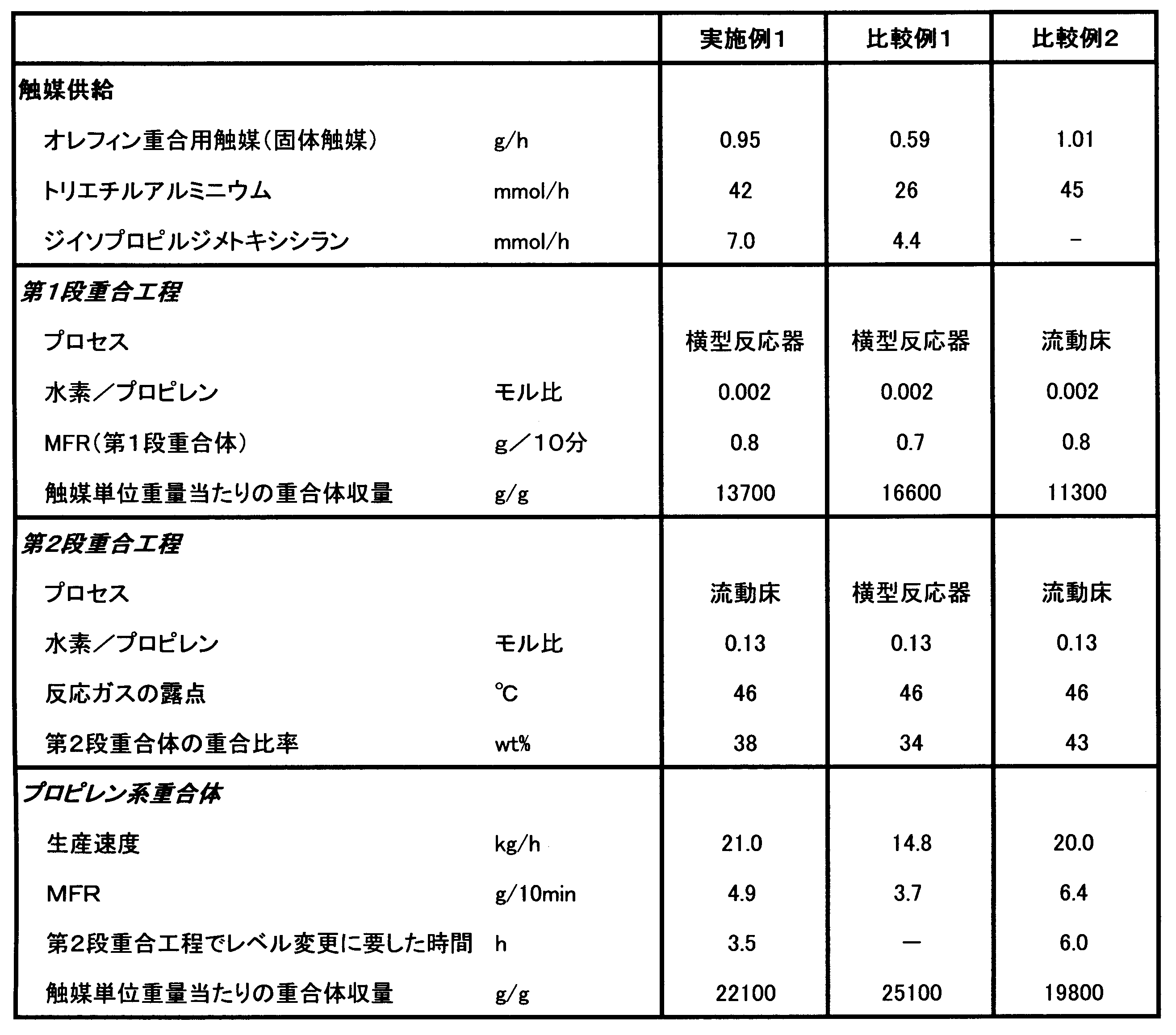
1)第1段重合工程
図8に示したフローシートによって説明する。攪拌羽根を有する横形反応槽(L/D=5.2、内容積100リットル)2槽(反応槽Aおよび反応槽B)を直列に設置し、実施例1に記載の予備活性化処理(予備重合処理)した固体触媒成分を0.51g/hr、有機アルミ化合物としてトリエチルアルミニウムおよび有機ケイ素化合物としてジイソプロピルジメトキシシランを、Al/Mgモル比が6、Al/Siモル比が6となるよう反応槽A(10)最上流部へ連続的に供給した。反応温度65℃、反応圧力2.2MPa、攪拌速度35rpmの条件を維持しながら、反応槽内の気相中の水素濃度を表1に示した水素/プロピレンモル比に維持するように、水素ガスを循環配管6より連続的に供給して、反応槽AのMFRを調節した。
反応熱は配管17から供給する原料液化プロピレンの気化熱により除去した。反応槽から排出される未反応ガスは配管13を通して反応槽系外で冷却、凝縮させて配管17にて反応槽A(10)に還流した。
生成した第1段重合の重合体は、重合体の保有レベルが反応容積の60容量%となる様に配管37を通して反応槽A(10)から間欠的に抜き出し、反応槽B(20-1)に供給した。
この時、配管41-1から重合体の一部を間欠的に採取して、MFRおよび触媒単位重量当たりの重合体収量を測定する試料とした。触媒単位重量当たりの重合体収量は、誘導結合プラズマ発光分光分析(ICP法)により測定した重合体中のMg含有量から算出した。
反応熱は配管27-1から供給する原料液化プロピレンの気化熱により除去した。反応槽から排出される未反応ガスは配管23を通して反応槽系外で冷却、凝縮させて配管27-1にて反応槽20-1に還流した。
反応槽Bで生成した重合体は、重合体の保有レベルが反応容積の60容量%となる様に配管38を通して反応槽B(20-1)から間欠的に抜き出し、第2反応槽である反応槽C(40-1)に供給した。
この時、配管42-1から重合体の一部を間欠的に採取して、MFRおよび触媒単位重量当たりの重合体収量を測定する試料とした。触媒単位重量当たりの重合体収量は、誘導結合プラズマ発光分光分析(ICP法)により測定した重合体中のMg含有量から算出した。
第1段重合工程に引き続き、内容積2000リットルの流動床反応槽にて第2段重合工程の重合を実施した。この流動床反応槽は、第1段重合工程の第2反応槽の直後に、直列に接続されたものである。反応温度60℃で、圧力2.0MPaになるように、プロピレンとエチレンをエチレン/プロピレンのモル比で0.33となるように連続的に供給し、更に、分子量制御剤としての水素を、水素/エチレンのモル比で0.01となるように連続的に供給すると共に、活性水素化合物(電子供与性化合物)としてエチルアルコールを、トリエチルアルミニウムに対して1.2倍モルになるように供給した。流動床式反応槽で重合したパウダーは、空塔速度が0.40m/secとなるように流動させ、また、反応槽内のパウダー保有量が、平均して40kgとなるように1回約2Kgずつ間欠的に、5~10分に1回ベッセルに抜き出し、更に別のベッセルに移送し、そこでは、水分を含んだ窒素ガスを供給して反応を停止、残留ガスをパージさせ、プロピレン系ブロック共重合体を得た。
更に、得られたプロピレン系ブロック共重合体4kgにフェノール系酸化防止剤として、ペンタエリスチル-テトラキス[3-(3,5-t-ブチル-4-ヒドロキシフェニル)プロピオネート]を2.0g、トリス-(2,4-ジ-t-ブチルフェニル)フオスフアイトを2.0g、中和剤として、ステアリン酸カルシウムを2.0g添加し、およびタルクを12g加え、高速攪拌式混合機(ヘンシェルミキサー)を用いて、室温下にて2分間混合し、混合物をスクリュウ径40mmの押出造粒機を用いて造粒した。次いで、造粒物からテストピースを射出成形機を用いて溶融樹脂温度250℃、金型温度50℃で作成した。得られたテストピースを湿度50%、室温23℃の室内で72時間状態調整して機械物性値を測定した。結果を表1に示す。
攪拌羽根を有する横形反応槽(L/D=5.2、内容積100リットル)2個を、第1反応槽、第2反応槽として、直列に連結してなる連続反応装置を用いて重合を行った。
まず、第1反応槽に実施例1に記載の予備活性化処理(予備重合処理)した固体触媒を0.53g/hr、有機アルミ化合物としてトリエチルアルミニウムおよび有機ケイ素化合物としてジイソプロピルジメトキシシランを、Al/Mgモル比が6、Al/Siモル比が6となるよう連続的に供給した。反応温度65℃、反応圧力2.2MPa、攪拌速度35rpmの条件を維持しながら、反応槽内の気相中の水素濃度を表1に示した水素/プロピレンモル比に維持するように、水素ガスを連続的に供給して、第1段重合体のMFRを調節した。生成した第1段重合の重合体は、重合体の保有レベルが反応容積の60容量%となる様に間欠的に抜き出し、第2段重合工程の反応槽に供給した(第1段重合工程)。
重合温度60℃で、圧力2.0MPaになるように、プロピレンとエチレンをエチレン/プロピレンのモル比で0.39となるように連続的に供給した。分子量制御剤としての水素の供給は行わなかった。活性水素化合物としてエチルアルコールを、トリエチルアルミニウムに対して1.1倍モルになるように供給した。第2反応槽で重合したパウダーは、重合体の保有レベルが反応容積の60容量%となる様に間欠的に抜き出し、水分を含んだ窒素ガスを供給して反応を停止させ、プロピレン系ブロック共重合体を得た(第2段重合工程)。
得られたプロピレン系ブロック共重合体4kgにフェノール系酸化防止剤として、ペンタエリスチル-テトラキス[3-(3,5-t-ブチル-4-ヒドロキシフェニル)プロピオネート]を2.0g、トリス-(2,4-ジ-t-ブチルフェニル)フオスフアイトを2.0g、中和剤として、ステアリン酸カルシウムを2.0g添加し、およびタルクを12g加え、高速攪拌式混合機(ヘンシェルミキサー)を用いて、室温下にて2分間混合し、混合物をスクリュウ径40mmの押出造粒機を用いて造粒した。次いで、造粒物からテストピースを射出成形機を用いて溶融樹脂温度250℃、金型温度50℃で作成した。得られたテストピースを湿度50%、室温23℃の室内で72時間状態調整して機械物性値を測定した。結果を表1に示す。

1)プロピレン系ブロック共重合体の製造
図12に示したフローシートによって説明する。攪拌翼を有する横型反応槽(L/D=5.2、内容積100リットル)1槽(反応槽A)と内容積2000リットルの流動床反応槽2槽(反応槽Cと反応槽D)を直列に配置したプロピレン重合装置にてプロピレン系ブロック共重合体の製造を実施した。
実施例1に記載の予備活性化処理(予備重合処理)した固体触媒を0.53g/hr、有機アルミニウム化合物としてトリエチルアルミニウムおよび有機ケイ素化合物としてジイソプロピルジメトキシシランを、Al/Mgモル比が6、Al/Siモル比が6となるよう反応槽A(10)最上流部へ連続的に供給した。反応温度65℃、反応圧力2.2MPa、攪拌速度35rpmの条件を維持しながら、反応槽内の気相中の水素濃度を表1に示した水素/プロピレンモル比に維持するように、水素ガスを配管6より連続的に供給して、反応槽AのMFRを調節した。
反応熱は配管17から供給する原料液化プロピレンの気化熱により除去した。反応槽から排出される未反応ガスは配管13を通して反応槽系外で冷却、凝縮させて配管17にて反応槽A(10)に還流した。
生成した第1段重合工程の重合体は、重合体の保有レベルが反応容積の60容量%となる様に配管37を通して反応槽A(10)から間欠的に抜き出した。
この時、配管37から重合体の一部を間欠的に採取して、MFRおよび触媒単位重量当たりの重合体収量を測定する試料とした。触媒単位重量当たりの重合体収量は、誘導結合プラズマ発光分光分析(ICP法)により測定した重合体中のMg含有量から算出した。第1段重合工程において重合した成分は、重合体成分(A)とした。
第1段重合工程に引き続き、内容積2000リットルの流動床式反応槽2槽(20-2及び40-2)にて第2段重合工程の重合を実施した。反応温度60℃で、圧力2.0MPaになるように、プロピレンとエチレンをエチレン/プロピレンのモル比で0.30となるように連続的に供給し、更に、分子量制御剤としての水素を、水素/エチレンのモル比で0.13となるように連続的に配管7-2から水素とエチレンを供給すると共に、活性水素化合物(電子供与性化合物)としてエチルアルコールを、トリエチルアルミニウムに対して0.5倍モルになるように配管7-2より供給した。流動床式反応槽20-2で重合したパウダーは、空塔速度が0.40m/secとなるように流動させ、また、反応槽内のパウダー保有量が、平均して40kgとなるように1回約2Kgずつ間欠的に、5~10分に1回脱ガス槽31に配管38より抜き出した。この時、配管38から重合体の一部を間歇的に採取して、MFRおよび赤外線吸収スペクトル分析によるエチレン含有量の測定、ICP法による重合体中のMg含量の測定による触媒単位重量当たりの重合体収量の算出に供した。本工程で重合した成分は、重合体成分(B1)とした。
更に別のベッセルに移送し、そこでは、水分を含んだ窒素ガスを供給して反応を停止、残留ガスをパージさせ、プロピレン系ブロック共重合体を得た。
得られたプロピレン系ブロック共重合体の一部はMFRの測定、および赤外線吸収スペクトル分析によるエチレン含有量の測定、ICP法による重合体中のMg含量の測定による共重合体の生成量、各種機械物性およびゲルの測定に供した。
1)プロピレン系ブロック共重合体の製造
内容積2000リットルの流動床式反応槽を2個連結してなる連続反応装置を用いて重合を行った。まず第1反応槽で、重合温度65℃、プロピレン分圧2.0MPa、分子量制御剤としての水素を、水素/プロピレンのモル比で0.27となるように連続的に供給するとともに、有機アルミニウム化合物としてトリエチルアルミニウムをAl/Mgモル比が6となるよう、25mmol/hにて、連続的に供給した。比較例2に記載の予備活性化処理(予備重合処理)した固体触媒をポリマー重合速度が12kg/時になるように供給した。第1反応槽で重合したパウダー(結晶性プロピレン重合体)は、空塔速度が0.35m/secとなるように流動させ、また、反応槽内のパウダー保有量が、平均して30kgとなるように1回約2Kgずつ間欠的に、5~10分に1回ベッセルに抜き出した後、更に第2反応槽に移送した(第1段重合工程)。第1段重合工程で重合した成分は、重合体成分(A)とした。MFRは135g/10分であった。触媒単位重量当たりの重合体収量は、誘導結合プラズマ発光分光分析(ICP法)により測定した重合体中のMg含有量から算出した。Mg含有量は、8.4ppmであった。
第1段重合工程に引き続き、内容積2000リットルの流動床式反応槽にて第2段重合工程の重合を実施した。第2反応槽では、重合温度60℃で、圧力2.0MPaになるように、プロピレンとエチレンをエチレン/プロピレンのモル比で0.32となるように連続的に供給し、更に、分子量制御剤としての水素を、水素/プロピレンのモル比で0.10となるように連続的に供給すると共に、活性水素化合物としてエチルアルコールを、トリエチルアルミニウムに対して0.8倍モルになるように供給した。第2反応槽で重合したパウダーは、空塔速度が0.40m/secとなるように流動させ、また、反応槽内のパウダー保有量が、平均して30kgとなるように1回約2Kgずつ間欠的に、5~10分に1回脱ガス槽に抜き出した後、更に別のベッセルに移送し、そこでは、水分を含んだ窒素ガスを供給して反応を停止、残留ガスをパージさせ、プロピレン系ブロック共重合体を得た(第2段重合工程)。第2段重合工程で重合した成分は、重合体成分(B1)とした。
攪拌翼を有する横型反応槽(L/D=5.2、内容積100リットル)を2個連結してなる連続反応装置を用いて重合を行った。
まず、第1反応槽に実施例1記載の予備活性化処理(予備重合処理)した固体触媒を0.45g/hr、有機アルミニウム化合物としてトリエチルアルミニウムおよび有機ケイ素化合物としてジイソプロピルジメトキシシランを、Al/Mgモル比が6、Al/Siモル比が6となるよう、それぞれ20mmol/h、3.3mmol/hにて、連続的に供給した。反応温度65℃、反応圧力2.2MPa、攪拌速度35rpmの条件を維持しながら、反応槽内の気相中の水素濃度を表1に示した水素/プロピレンモル比に維持するように、水素ガスを連続的に供給して、第1段重合体のMFRを調節した。生成した第1段重合の重合体は、重合体の保有レベルが反応容積の60容量%となる様に間欠的に抜き出し、第2段重合工程の反応槽に供給した(第1段重合工程)。第1段重合工程で重合した成分は、重合体成分(A)とした。MFRは143g/10分であった。
第1段重合工程に引き続き、横型反応槽(L/D=5.2、内容積100リットル)にて第2段重合工程の重合を実施した。重合温度60℃で、圧力2.0MPaになるように、プロピレンとエチレンをエチレン/プロピレンのモル比で0.32となるように連続的に供給し、更に、分子量制御剤としての水素を、水素/エチレンのモル比で0.13となるように連続的に供給すると共に、活性水素化合物としてエチルアルコールを、トリエチルアルミニウムに対して0.3倍モルになるように供給した。第2反応槽で重合したパウダーは、重合体の保有レベルが反応容積の60容量%となる様に間欠的に抜き出し、水分を含んだ窒素ガスを供給して反応を停止させ、プロピレン系ブロック共重合体を得た(第2段重合工程)。第2段重合工程で重合した成分は、重合体成分(B1)とした。
得られたプロピレン系ブロック共重合体4kgにフェノール系酸化防止剤として、ペンタエリスチル-テトラキス[3-(3,5-t-ブチル-4-ヒドロキシフェニル)プロピオネート]を2.0g、トリス-(2,4-ジ-t-ブチルフェニル)フォスファイトを2.0g、中和剤として、ステアリン酸カルシウムを2.0g添加し、およびタルクを12g加え、高速攪拌式混合機(ヘンシェルミキサー)を用いて、室温下にて2分間混合し、混合物をスクリュウ径40mmの押出造粒機を用いて造粒した。次いで、造粒物からテストピースを射出成形機を用いて溶融樹脂温度250℃、金型温度50℃で作成した。得られたテストピースを湿度50%、室温23℃の室内で72時間状態調整して機械物性値を測定した。結果を表1に示す。

1)第1段重合工程
図16に示したフローシートによって説明する。攪拌羽根を有する横形重合器(L/D=5.2、内容積100リットル)に実施例1に記載の予備活性化処理(予備重合処理)した固体触媒を0.53g/hr、有機アルミ化合物としてトリエチルアルミニウムおよび有機ケイ素化合物としてジイソプロピルジメトキシシランを、Al/Mgモル比が6、Al/Siモル比が6となるよう、それぞれ24mmol/h、3.9mmol/hにて、連続的に供給した。反応温度65℃、反応圧力2.2MPa、攪拌速度35rpmの条件を維持しながら、重合器内の気相中の水素濃度を表1に示した水素/プロピレンモル比に維持するように、水素ガスを循環配管4-1より連続的に供給して、第1段重合体のMFRを調節した。
生成した第1段重合の重合体は、重合体の保有レベルが反応容積の60容量%となる様に配管32-1を通して重合器10から間欠的に抜き出し、第2段重合工程の重合器20-2に供給した。第1段重合工程から第2段重合工程への重合体の移送は、以下のバルブシーケンス動作に基づいて実施した。
a)第1段重合反応槽内の粉面の上昇を感知して弁Wが開き、受器30の容積に対し60容積%まで受入れる、
b)弁Wを閉じた後、弁Zを開け、受器30の圧力が0.1MPaとなるまで排ガスする、
c)弁Zを閉じた後、弁Yを開けプロピレンガスにて受器30を2.2MPaまで加圧する、
d)弁Xを開け受器中の重合体を第2段重合工程へ導入し、受器に設置されたレベル計が
5容量%を示した後、1秒後に弁Xを閉める。
この時、配管32-1から重合体の一部を間欠的に採取して、MFRおよび触媒単位重量当たりの重合体収量を測定する試料とした。MFRは145g/10分であった。触媒単位重量当たりの重合体収量は、誘導結合プラズマ発光分光分析(ICP法)により測定した重合体中のMg含有量から算出した。
第1段重合工程に引き続き、内容積2000リットルの流動床式反応槽にて第2段重合工程の重合を実施した。反応温度60℃で、圧力2.0MPaになるように、プロピレンとエチレンをエチレン/プロピレンのモル比で0.3となるように連続的に供給し、更に、分子量制御剤としての水素を、水素/エチレンのモル比で0.13となるように連続的に供給すると共に、活性水素化合物としてエチルアルコールを、トリエチルアルミニウムに対して0.4倍モルになるように供給した。第2反応槽で重合したパウダーは、空塔速度が0.40m/secとなるように流動させ、また、反応槽内のパウダー保有量が、平均して30kgとなるように1回約2Kgずつ間欠的に、5~10分に1回ベッセルに抜き出し、更に別のベッセルに移送し、そこでは、水分を含んだ窒素ガスを供給して反応を停止、残留ガスをパージさせ、プロピレン系ブロック共重合体を得た。
更に、得られたプロピレン系ブロック共重合体4kgにフェノール系酸化防止剤として、ペンタエリスチル-テトラキス[3-(3,5-t-ブチル-4-ヒドロキシフェニル)プロピオネート]を2.0g、トリス-(2,4-ジ-t-ブチルフェニル)フォスファイトを2.0g、中和剤として、ステアリン酸カルシウムを2.0g添加し、およびタルクを12g加え、高速攪拌式混合機(ヘンシェルミキサー)を用いて、室温下にて2分間混合し、混合物をスクリュウ径40mmの押出造粒機を用いて造粒した。次いで、造粒物からテストピースを射出成形機を用いて溶融樹脂温度250℃、金型温度50℃で作成した。得られたテストピースを湿度50%、室温23℃の室内で72時間状態調整して機械物性値を測定した。結果を表1に示す。
第1段重合工程での水素/プロピレン比、第2段重合工程での水素/エチレン比、エチレン/プロピレン比およびエタノール/TEA比を変えた以外、およびプロピレン系ブロック共重合体を造粒する際、タルクを除いた以外は実施例4に準拠して実施した。結果を表1に示す。
攪拌羽根を有する横形重合器(L/D=5.2、内容積100リットル)を2個連結してなる連続反応装置を用いて重合を行った。
まず、第1反応槽に実施例1記載の予備活性化処理(予備重合処理)した固体触媒を0.45g/hr、有機アルミ化合物としてトリエチルアルミニウムおよび有機ケイ素化合物としてジイソプロピルジメトキシシランを、Al/Mgモル比が6、Al/Siモル比が6となるよう、それぞれ20mmol/h、3.3mmol/hにて、連続的に供給した。反応温度65℃、反応圧力2.2MPa、攪拌速度35rpmの条件を維持しながら、重合器内の気相中の水素濃度を表1に示した水素/プロピレンモル比に維持するように、水素ガスを連続的に供給して、第1段重合体のMFRを調節した。生成した第1段重合の重合体は、重合体の保有レベルが反応容積の60容量%となる様に間欠的に抜き出し、第2段重合工程の重合器に供給した(第1段重合工程)。なお、第1段重合工程から第2段重合工程への重合体の移送は、受器(30)に設置されたレベル計を使用し、実施例1記載の受器(30)バルブシーケンス動作に基づいて実施した。MFRは76g/10分であった。
第1段重合工程に引き続き、横形重合器(L/D=5.2、内容積100リットル)にて第2段重合工程の重合を実施した。重合温度60℃で、圧力2.0MPaになるように、プロピレンとエチレンをエチレン/プロピレンのモル比で0.32となるように連続的に供給し、更に、分子量制御剤としての水素を、水素/エチレンのモル比で0.13となるように連続的に供給すると共に、活性水素化合物としてエチルアルコールを、トリエチルアルミニウムに対して0.3倍モルになるように供給した。第2反応槽で重合したパウダーは、重合体の保有レベルが反応容積の60容量%となる様に間欠的に抜き出し、水分を含んだ窒素ガスを供給して反応を停止させ、プロピレン系ブロック共重合体を得た(第2段重合工程)。
得られたプロピレン系ブロック共重合体の一部はMFRの測定、および赤外線吸収スペクトル分析によるエチレン含有量の測定、ICP法による重合体中のMg含量の測定による共重合体の生成量、各種機械物性およびゲルの測定に供した。MFRは32g/10分、第2段重合工程で製造された第2段重合体の重合比率は、得られたプロピレン系ブロック共重合体全体を基準として28重量%、また、第2段重合体中のエチレンの重合比は、第2段重合工程で重合された重合体を基準として37重量%であった。
得られたプロピレン系ブロック共重合体4kgにフェノール系酸化防止剤として、ペンタエリスチル-テトラキス[3-(3,5-t-ブチル-4-ヒドロキシフェニル)プロピオネート]を2.0g、トリス-(2,4-ジ-t-ブチルフェニル)フォスファイトを2.0g、中和剤として、ステアリン酸カルシウムを2.0g添加し、およびタルクを12g加え、高速攪拌式混合機(ヘンシェルミキサー)を用いて、室温下にて2分間混合し、混合物をスクリュウ径40mmの押出造粒機を用いて造粒した。次いで、造粒物からテストピースを射出成形機を用いて溶融樹脂温度250℃、金型温度50℃で作成した。得られたテストピースを湿度50%、室温23℃の室内で72時間状態調整して機械物性値を測定した。結果を表1に示す。
第1段重合工程での水素/プロピレン比、第2段重合工程での水素/エチレン比、エチレン/プロピレン比およびエタノール/TEA比を変えた以外、およびプロピレン系ブロック共重合体を造粒する際、タルクを除いた以外は比較例6に準拠して実施した。結果を表1に示す。
1)重合
内容積2000リットルの流動床式反応槽を2個連結してなる連続反応装置を用いて重合を行った。まず第1反応槽で、重合温度65℃、プロピレン分圧2.0MPa、分子量制御剤としての水素を、水素/プロピレンのモル比で0.27となるように連続的に供給するとともに、有機アルミ化合物としてトリエチルアルミニウムをAl/Mgモル比が6となるよう、25mmol/hにて、連続的に供給した。比較例2に記載の予備活性化処理(予備重合処理)した固体触媒をポリマー重合速度が12kg/時になるように供給した。第1反応槽で重合したパウダー(結晶性プロピレン重合体)は、空塔速度が0.35m/secとなるように流動させ、また、反応槽内のパウダー保有量が、平均して30kgとなるように1回約2Kgずつ間欠的に、5~10分に1回ベッセルに抜き出した後、更に第2反応槽に移送した(第1段重合工程)。なお、第1段重合工程から第2段重合工程への重合体の移送は、受器(30)に設置されたレベル計を使用し、実施例1記載の受器(30)バルブシーケンス動作に基づいて実施した。MFRは135g/10分であった。
第1段重合工程に引き続き、内容積2000リットルの流動床式反応槽にて第2段重合工程の重合を実施した。第2反応槽では、重合温度60℃で、圧力2.0MPaになるように、プロピレンとエチレンをエチレン/プロピレンのモル比で0.32となるように連続的に供給し、更に、分子量制御剤としての水素を、水素/プロピレンのモル比で0.10となるように連続的に供給すると共に、活性水素化合物としてエチルアルコールを、トリエチルアルミニウムに対して0.8倍モルになるように供給した。第2反応槽で重合したパウダーは、空塔速度が0.40m/secとなるように流動させ、また、反応槽内のパウダー保有量が、平均して30kgとなるように1回約2Kgずつ間欠的に、5~10分に1回ベッセルに抜き出した後、更に別のベッセルに移送し、そこでは、水分を含んだ窒素ガスを供給して反応を停止、残留ガスをパージさせ、プロピレン系ブロック共重合体を得た(第2段重合工程)。
得られたプロピレン系ブロック共重合体の一部はMFRの測定、および赤外線吸収スペクトル分析によるエチレン含有量の測定、ICP法による重合体中のMg含量の測定による共重合体の生成量、各種機械物性およびゲルの測定に供した。MFRは30g/10分、第2段重合工程で製造された第2段重合体の重合比率は、得られたプロピレン系ブロック共重合体全体を基準として26重量%、また、第2段重合体中のエチレンの重合比は、第2段重合工程で重合された重合体を基準として38重量%であった。
得られたプロピレン系ブロック共重合体4kgにフェノール系酸化防止剤として、ペンタエリスチル-テトラキス[3-(3,5-t-ブチル-4-ヒドロキシフェニル)プロピオネート]を2.0g、トリス-(2,4-ジ-t-ブチルフェニル)フォスファイトを2.0g、中和剤として、ステアリン酸カルシウムを2.0g添加し、およびタルクを12g加え、高速攪拌式混合機(ヘンシェルミキサー)を用いて、室温下にて2分間混合し、混合物をスクリュウ径40mmの押出造粒機を用いて造粒した。次いで、造粒物からテストピースを射出成形機を用いて溶融樹脂温度250℃、金型温度50℃で作成した。得られたテストピースを湿度50%、室温23℃の室内で72時間状態調整して機械物性値を測定した。結果を表1に示す。
第1段重合工程での水素/プロピレン比、第2段重合工程での水素/エチレン比、エチレン/プロピレン比およびエタノール/TEA比を変えた以外、およびプロピレン系ブロック共重合体を造粒する際、タルクを除いた以外は比較例8に準拠して実施した。結果を表1に示す。
受器(30)の弁(B)作動シーケンスにおいてレベル計作動を使用せず、受器(30)の圧力が2.1MPaとなった時点で閉めるようにした以外は実施例4に準拠して実施した。

従って、実施例1により、低い露点の反応ガス条件を必要とする重合成分を含むプロピレン多段連続気相重合体の製造方法において、本発明の特定事項である、横型反応槽と完全混合槽が組み合わされたプロピレン重合反応装置の使用をすることで、高い生産性を維持できるばかりでなく、重合条件(滞留時間)の変更を行なう場合、その調整が極めて容易(短時間)という点で、優れた結果が得られることが確認された。
加えて2槽目の横型反応槽における水素濃度を制御することで、第2段重合工程における水素濃度をより低下させることが可能となり、共重合体成分の分子量もより高くすることが可能であることが分かる。
従って、実施例はプロピレン系ブロック共重合体の製造方法において、本発明の製造方法の特定事項である、各重合工程でのプロセスを規定することで、ゲル発生の抑制およびより高い分子量の共重合体成分を製造するという点で、優れた結果が得られていると言える。また、本発明の製造方法の実施例によるポリプロピレン系ブロック共重合体組成物は、流動性維持の目標であるMFRが25g/10分以上との値も満たしている。
従って、実施例はプロピレン系ブロック共重合体の製造方法において、本発明の製造方法の特定事項である、各重合工程でのプロセスを規定することで、ゲル発生の抑制およびより高い含有量の共重合体成分及びよりα-オレフィン含有量の多い共重合体成分を製造するという点で、優れた結果が得られていると言える。
具体的には実施例4と比較例6の比較において、第2段重合工程を「完全混合槽型反応槽」とすることで、光沢が抑制されることが分かる。また、実施例4と比較例8の比較において、第1段重合工程を「内部に水平軸回りに回転する撹拌機を有する横型反応槽」とすることで、ゲルの発生が抑制されることが分かる
実施例4と比較例10では、いずれも「内部に水平軸回りに回転する撹拌機を有する横型反応槽と、該横型反応槽に連結する完全混合槽とが、それぞれ少なくとも1槽以上具備される装置」にてプロピレン/α-オレフィン共重合体成分を製造する例であるが、第1段重合工程から第2段重合工程へ重合体を移送する際、レベル計を使用せず、受器の圧力変化にてシーケンス作動させた例である。この場合、第2段重合工程における反応ガス組成の乱れ(変動)が大きくなり、結果としてプロピレン系ブロック共重合体の光沢が上昇することが分かる。これは、第2段重合工程にて、より均一な反応ガス組成が得られる「完全混合槽型反応槽」を採用したにもかかわらず、その重合体移送工程において反応ガス組成の乱れを生じさせ、結果、プロピレン系ブロック共重合体中のエチレン分布が広くなったためである。
従って、実施例4及び5により、本発明の特定事項である、重合装置の使用、各重合工程でのプロセスを規定すること、および本発明で開示された重合体の移送方法の使用で、光沢およびゲル発生の抑制という点で、優れた結果が得られることが確認された。
また、本発明の装置及び製造方法によれば、ゲルの発生を抑制されたプロピレン系ブロック共重合体が得られることから、外観および剛性/耐低温衝撃性に優れた射出成形品等を得ることが可能である。加えて、連続気相重合方法であることから、より安価で品質的に安定したプロピレン系ブロック共重合体の供給が可能となる。
また、本発明の装置及び製造方法によれば、自動車部材や家電部材等に好適な、剛性/耐衝撃性のバランスに優れ、加えてゲルの発生が抑制されたプロピレン系ブロック重合体を、反応槽内の付着が抑制され、安定的に効率良く製造出来る。加えて、連続気相重合方法であることから、より安価で品質的に安定したプロピレン系ブロック共重合体の供給が可能となる。そして、完全混合槽を2槽以上設置することで、プロピレン系ブロック共重合体の共重合体成分の含有量を高め易くなるばかりでなく、2槽以上で共重合体成分を製造する場合、各槽で異なるα-オレフィン含有量及び/又は分子量の共重合体成分とすることで、更なる品質の向上・多様性が図れる。
また、本発明の装置及び製造方法によれば、光沢とゲルの発生を抑制されたプロピレン系ブロック共重合体が得られることから、外観の優れた射出成形品や押し出し成形品を得ることが可能である。加えて、連続気相重合方法であることから、より安価で品質的に安定したプロピレン系ブロック共重合体の供給が可能となる。
したがって、本発明の装置及び製造方法は産業上大いに有用である。
3、4-2、5 原料プロピレン補給配管
4-1、6、7、8 原料補給配管(水素・エチレンなど)
7-2、8-2 電子供与性化合物供給配管
10 横型反応槽
11、21 気液分離槽
12、22 反応槽上流末端
13、23、33-2 未反応ガス抜出し配管
14、24 反応槽下流末端
15、25-2 凝縮器
16、26、36 圧縮器
17、27-1 原料液化プロピレン補給配管
18、28 原料混合ガス供給配管
20-1 横型反応槽
20-2 完全混合槽
25-1、45 循環ガスクーラー
30-2 受器(レベル計設置されている)
30-1、31、32-2 受器
32-1、33-1、37、38、39 重合体抜出し配管
40-1、40-2 完全混合槽
25-3、27-2、34、41-1、42-1 重合体供給配管
41-2 加圧ガス供給配管
42-2 ガス排出配管
W 重合体排出弁
X 重合体移送弁
Y ガス導入弁
Z ガス排出弁
Claims (25)
- プロピレン系重合体を多段連続気相重合法で製造するための反応装置であって、内部に水平軸回りに回転する撹拌機を有する横型反応槽と、該横型反応槽に連結する完全混合槽とが、それぞれ少なくとも1槽以上具備されていることを特徴とするプロピレン重合反応装置。
- 前記横型反応槽の直後に、前記完全混合槽が設けられることを特徴とする請求項1に記載のプロピレン重合反応装置。
- 少なくとも2槽の前記横型反応槽が具備されていることを特徴とする請求項1に記載のプロピレン重合反応装置。
- 前記横型反応槽のうち少なくとも2槽を、前記完全混合槽のうち最もプロセス上流に配置される完全混合槽より、上流側に配置してなることを特徴とする請求項3に記載のプロピレン重合反応装置。
- プロセス上流側から、前記横型反応槽のうちの1槽-前記横型反応槽のうちの別の1槽-前記完全混合槽のうちの1槽との順番で配置してなることを特徴とする請求項3に記載のプロピレン重合反応装置。
- 少なくとも2槽の前記完全混合槽と具備されていることを特徴とする請求項1に記載のプロピレン重合反応装置。
- 前記横型反応槽のうち少なくとも1槽を、前記完全混合槽のうち最もプロセス上流に配置される完全混合槽より、上流側に配置してなることを特徴とする請求項6に記載のプロピレン重合反応装置。
- プロセス上流側から、前記横型反応槽のうちの1槽-前記完全混合槽のうちの1槽-前記完全混合槽のうちの別の1槽との順番で配置してなることを特徴とする請求項6に記載のプロピレン重合反応装置。
- 横型反応槽と完全混合槽との間には、少なくとも1つのレベル計を有する受器が設けられ、両槽間を移送すべき重合体の量を制御することを特徴とする請求項1~8のいずれか1項に記載のプロピレン重合反応装置。
- 前記横型反応槽の直後に、受器を介して前記完全混合槽が設けられることを特徴とする請求項9に記載のプロピレン重合反応装置。
- 前記受器は、前記横型反応槽の重合体抜き出し口の直下であって、かつ、前記完全混合槽の重合体入り口より高い位置に配置されることを特徴とする請求項9または10に記載のプロピレン重合反応装置。
- 前記受器は、ガス導入弁及びガス排出弁を備えるものであることを特徴とする請求項9~11のいずれか1項に記載のプロピレン重合反応装置。
- 前記完全混合槽は、主に循環ガスの顕熱を利用して重合熱の除去を行なう反応槽であることを特徴とする請求項1~12のいずれか1項に記載のプロピレン重合反応装置。
- 前記完全混合槽は、縦型撹拌槽、攪拌式流動床反応槽または流動床反応槽から選ばれる反応槽であることを特徴とする請求項1~13のいずれか1項に記載のプロピレン重合反応装置。
- 前記完全混合槽は、流動床反応槽であることを特徴とする請求項1~13のいずれか1項にプロピレン重合反応装置。
- 前記横型反応槽は、L/Dが5以上(L:水平長手方向の長さ、D:内径)であることを特徴とする請求項1~15のいずれか1項に記載のプロピレン重合反応装置。
- 請求項1~16のいずれか1項に記載のプロピレン重合反応装置を用いて、オレフィン重合用触媒の存在下にプロピレンの多段連続気相重合を行なうことを特徴とするプロピレン系重合体の製造方法。
- 前記完全混合槽における重合反応は、露点が50℃以下である反応ガスを用いて行なうことを特徴とする請求項17に記載のプロピレン系重合体の製造方法。
- 前記横型反応槽においてプロピレンを単独重合又はプロピレンとα-オレフィン(但し、プロピレンを除く)とを共重合して、プロピレンに基づく単量体単位の含有量が95重量%以上である重合体成分(A)を製造する第1段重合工程を行ない、引き続き、前記完全混合槽においてプロピレンとα-オレフィン(但し、プロピレンを除く)とを共重合して、プロピレンに基づく単量体単位の含有量が95~5重量%である共重合体成分(B)を製造する第2段重合工程を行なうことを特徴とする請求項17に記載のプロピレン系ブロック共重合体の製造方法。
- 第1段重合工程が、少なくとも1槽の前記横型反応槽にて行われることを特徴とする請求項19に記載のプロピレン系ブロック共重合体の製造方法。
- 第2段重合工程が、少なくとも1槽の前記完全混合槽にて行われることを特徴とする請求項19に記載のプロピレン系ブロック共重合体の製造方法。
- 請求項3~5のいずれか1項に記載のプロピレン重合反応装置を用いて、オレフィン重合用触媒の存在下にプロピレンの多段連続気相重合を行なうプロピレン系重合体の製造方法であって、
第1段重合工程が、少なくとも2槽の前記横型反応槽にて行われることを特徴とするプロピレン系ブロック共重合体の製造方法。 - 請求項6~8のいずれか1項に記載のプロピレン重合反応装置を用いて、オレフィン重合用触媒の存在下にプロピレンの多段連続気相重合を行なうプロピレン系重合体の製造方法であって、
第2段重合工程は、少なくとも2槽の前記完全混合槽にて行われることを特徴とするプロピレン系ブロック共重合体の製造方法。 - 重合体成分(A)のメルトフローレート(MFR1)と共重合体成分(B)のメルトフローレート(MFR2)が、3≦log(MFR1/MFR2)≦7の関係を満たすことを特徴とする請求項19~23のいずれか1項に記載のプロピレン系ブロック共重合体の製造方法
- 前記完全混合槽のそれぞれにおいて製造する共重合体成分は、α-オレフィンの含有量及び/又は分子量が異なることを特徴とする請求項23に記載のプロピレン系ブロック共重合体の製造方法。
Priority Applications (3)
| Application Number | Priority Date | Filing Date | Title |
|---|---|---|---|
| EP10828361.5A EP2497786B1 (en) | 2009-11-06 | 2010-11-05 | Reactor for propylene polymerization and process for producing propylene polymer |
| US13/505,852 US8735513B2 (en) | 2009-11-06 | 2010-11-05 | Reactor for propylene polymerization and process for producing propylene polymer |
| CN201080060910.9A CN102695728B (zh) | 2009-11-06 | 2010-11-05 | 丙烯聚合用反应器和丙烯聚合物的生产方法 |
Applications Claiming Priority (4)
| Application Number | Priority Date | Filing Date | Title |
|---|---|---|---|
| JP2009-254892 | 2009-11-06 | ||
| JP2009254892 | 2009-11-06 | ||
| JP2009-254898 | 2009-11-06 | ||
| JP2009254898 | 2009-11-06 |
Publications (1)
| Publication Number | Publication Date |
|---|---|
| WO2011055802A1 true WO2011055802A1 (ja) | 2011-05-12 |
Family
ID=43970038
Family Applications (1)
| Application Number | Title | Priority Date | Filing Date |
|---|---|---|---|
| PCT/JP2010/069752 Ceased WO2011055802A1 (ja) | 2009-11-06 | 2010-11-05 | プロピレン重合反応装置及びプロピレン系重合体の製造方法 |
Country Status (5)
| Country | Link |
|---|---|
| US (1) | US8735513B2 (ja) |
| EP (1) | EP2497786B1 (ja) |
| JP (2) | JP5568446B2 (ja) |
| CN (1) | CN102695728B (ja) |
| WO (1) | WO2011055802A1 (ja) |
Cited By (4)
| Publication number | Priority date | Publication date | Assignee | Title |
|---|---|---|---|---|
| CN103387628A (zh) * | 2012-05-07 | 2013-11-13 | 中国石油化工股份有限公司 | 一种烯烃聚合的系统及方法 |
| CN104245819A (zh) * | 2011-11-11 | 2014-12-24 | 巴塞尔聚烯烃意大利有限公司 | 用于减震器和内部材料的聚合物组合物以及聚乙烯基树脂前体 |
| CN112439378A (zh) * | 2020-10-21 | 2021-03-05 | 贵州凯襄新材料有限公司 | 一种混凝土减水剂制备装置 |
| EP3885376A1 (en) | 2020-02-14 | 2021-09-29 | Sumitomo Chemical Company Limited | Production method of propylene polymer |
Families Citing this family (11)
| Publication number | Priority date | Publication date | Assignee | Title |
|---|---|---|---|---|
| JP5859339B2 (ja) * | 2011-08-15 | 2016-02-10 | 三菱重工業株式会社 | チャー回収装置 |
| JP5862501B2 (ja) * | 2012-07-27 | 2016-02-16 | 日本ポリプロ株式会社 | 結晶化度が調整された結晶性プロピレン重合体の連続製造方法 |
| JP6052075B2 (ja) * | 2013-06-20 | 2016-12-27 | 日本ポリプロ株式会社 | プロピレン系ブロック共重合体の製造方法 |
| JP6902337B2 (ja) | 2016-08-03 | 2021-07-14 | 住友化学株式会社 | ヘテロファジックプロピレン重合材料の製造方法 |
| WO2019074051A1 (ja) * | 2017-10-12 | 2019-04-18 | 株式会社クレハ | 重合体の連続製造装置および連続製造方法 |
| CN111875725A (zh) * | 2020-06-17 | 2020-11-03 | 南京延长反应技术研究院有限公司 | 一种浆液法制备聚乙烯的微界面强化反应系统及方法 |
| CN112250778B (zh) * | 2020-09-14 | 2022-05-13 | 杭州双安科技有限公司 | 一种丙烯聚合物的生产方法 |
| CN112755951B (zh) * | 2021-01-29 | 2022-07-19 | 福建未来药业有限公司 | 一种酶催化医药中间体制备用反应釜 |
| CN116059665B (zh) * | 2021-10-29 | 2024-11-08 | 中国石油化工股份有限公司 | 丙酮合成甲基异丁基酮的装置及方法 |
| CN120769871A (zh) | 2023-03-13 | 2025-10-10 | 日本聚丙烯株式会社 | 丙烯系聚合物的制造方法 |
| EP4527497A1 (en) | 2023-09-19 | 2025-03-26 | Lummus Novolen Technology GmbH | Energy-efficient polypropylene production by reducing power consumption of heat rejection system |
Citations (24)
| Publication number | Priority date | Publication date | Assignee | Title |
|---|---|---|---|---|
| JPS4734478A (ja) | 1971-03-23 | 1972-11-21 | ||
| JPS5765703A (en) | 1980-10-09 | 1982-04-21 | Mitsui Petrochem Ind Ltd | Vapor-phase polymerization of olefin |
| JPS585310A (ja) | 1981-07-03 | 1983-01-12 | Mitsubishi Petrochem Co Ltd | オレフイン重合用触媒成分 |
| JPS5823806A (ja) | 1981-08-04 | 1983-02-12 | Chisso Corp | α−オレフイン重合体を製造する方法 |
| JPS5883006A (ja) | 1981-11-13 | 1983-05-18 | Mitsui Petrochem Ind Ltd | オレフインの重合方法 |
| JPS58157808A (ja) | 1982-03-16 | 1983-09-20 | Ube Ind Ltd | α−オレフインの重合方法 |
| JPS6166705A (ja) * | 1984-09-11 | 1986-04-05 | Chisso Corp | プロピレンの連続気相重合方法 |
| JPS61218606A (ja) | 1985-03-25 | 1986-09-29 | Sumitomo Chem Co Ltd | α−オレフイン重合体の製造法 |
| JPS63146906A (ja) | 1986-09-26 | 1988-06-18 | ソルベイ(ソシエテ アノニム) | アルフアーオレフインの立体特異性重合に使用できる固形触媒 |
| JPH0365366A (ja) | 1989-08-04 | 1991-03-20 | Toshiba Corp | プリンタ収納デスク |
| JPH05295022A (ja) | 1992-04-23 | 1993-11-09 | Mitsubishi Kasei Corp | オレフィン重合用触媒およびオレフィン重合体の製造方法 |
| JPH07118342A (ja) | 1993-10-20 | 1995-05-09 | Asahi Chem Ind Co Ltd | オレフィンの気相重合方法 |
| JP2675919B2 (ja) | 1992-05-29 | 1997-11-12 | アモコ・コーポレーション | α−オレファン類の重合 |
| JP2002030127A (ja) | 2000-07-19 | 2002-01-31 | Grand Polymer Co Ltd | プロピレン系ブロック共重合体およびその製造方法 |
| JP2002265516A (ja) | 2001-03-12 | 2002-09-18 | Japan Polychem Corp | プロピレン系ブロック共重合体の製造方法 |
| JP2004124090A (ja) | 2002-09-11 | 2004-04-22 | Japan Polypropylene Corp | α−オレフィン重合用触媒及びそれを用いるα−オレフィン重合体の製造方法 |
| JP2004217896A (ja) | 2002-12-26 | 2004-08-05 | Sunallomer Ltd | ポリプロピレン系樹脂組成物 |
| JP3852957B2 (ja) | 1997-06-24 | 2006-12-06 | ボレアリス エイ/エス | プロピレンホモポリマーおよびコポリマーを製造する方法および装置 |
| JP2007084645A (ja) * | 2005-09-21 | 2007-04-05 | Sumitomo Chemical Co Ltd | オレフィン重合体の製造方法および多段重合反応装置 |
| JP2007321136A (ja) | 2006-06-05 | 2007-12-13 | Japan Polypropylene Corp | ポリプロピレン系ブロック共重合体の製造方法 |
| JP2008115321A (ja) * | 2006-11-07 | 2008-05-22 | Japan Polypropylene Corp | ポリプロピレン系ランダム共重合体、それを含む組成物および射出成形体の製造方法 |
| JP2008260546A (ja) | 2007-04-11 | 2008-10-30 | Japan Polypropylene Corp | 低光沢容器 |
| JP4217272B2 (ja) | 2003-04-08 | 2009-01-28 | 日本ポリプロ株式会社 | プロピレン−エチレンブロック共重合体の製造方法 |
| JP2009073890A (ja) * | 2007-09-19 | 2009-04-09 | Japan Polypropylene Corp | プロピレン系重合体の製造方法 |
Family Cites Families (10)
| Publication number | Priority date | Publication date | Assignee | Title |
|---|---|---|---|---|
| SE376428B (ja) * | 1969-01-21 | 1975-05-26 | Pechiney Saint Gobain Sa Prod | |
| US4130699A (en) * | 1977-11-25 | 1978-12-19 | Standard Oil Company (Indiana) | Vapor phase polymerization with temporarily inactive titanium catalyst |
| CN1014523B (zh) * | 1987-01-24 | 1991-10-30 | 国家医药管理局上海医药设计院 | 烯烃多段聚合方法 |
| JPH04217272A (ja) | 1990-12-18 | 1992-08-07 | Ricoh Co Ltd | 画像出力装置 |
| KR100267187B1 (ko) * | 1997-12-26 | 2000-10-16 | 황규억 | 발포 스티렌 수지의 제조장치 |
| US6184299B1 (en) * | 1999-03-31 | 2001-02-06 | Union Carbide Chemicals & Plastics Technology Corporation | Staged reactor process |
| CN100497404C (zh) * | 2003-09-03 | 2009-06-10 | 中国石油化工集团公司 | 丙烯多段聚合工艺及聚合反应器 |
| CN1887916A (zh) * | 2005-06-30 | 2007-01-03 | 高煦 | 气相多段聚合方法及聚合反应器 |
| CN101379097B (zh) * | 2006-02-03 | 2011-08-03 | 日本聚丙烯公司 | 丙烯类聚合物及其制备方法、丙烯类聚合物组合物以及由该组合物制成的成型制品 |
| JP2008247999A (ja) * | 2007-03-29 | 2008-10-16 | Sumitomo Chemical Co Ltd | ポリプロピレンの製造方法 |
-
2010
- 2010-11-05 US US13/505,852 patent/US8735513B2/en active Active
- 2010-11-05 CN CN201080060910.9A patent/CN102695728B/zh active Active
- 2010-11-05 EP EP10828361.5A patent/EP2497786B1/en active Active
- 2010-11-05 WO PCT/JP2010/069752 patent/WO2011055802A1/ja not_active Ceased
- 2010-11-05 JP JP2010248934A patent/JP5568446B2/ja active Active
- 2010-11-05 JP JP2010248939A patent/JP5484290B2/ja active Active
Patent Citations (24)
| Publication number | Priority date | Publication date | Assignee | Title |
|---|---|---|---|---|
| JPS4734478A (ja) | 1971-03-23 | 1972-11-21 | ||
| JPS5765703A (en) | 1980-10-09 | 1982-04-21 | Mitsui Petrochem Ind Ltd | Vapor-phase polymerization of olefin |
| JPS585310A (ja) | 1981-07-03 | 1983-01-12 | Mitsubishi Petrochem Co Ltd | オレフイン重合用触媒成分 |
| JPS5823806A (ja) | 1981-08-04 | 1983-02-12 | Chisso Corp | α−オレフイン重合体を製造する方法 |
| JPS5883006A (ja) | 1981-11-13 | 1983-05-18 | Mitsui Petrochem Ind Ltd | オレフインの重合方法 |
| JPS58157808A (ja) | 1982-03-16 | 1983-09-20 | Ube Ind Ltd | α−オレフインの重合方法 |
| JPS6166705A (ja) * | 1984-09-11 | 1986-04-05 | Chisso Corp | プロピレンの連続気相重合方法 |
| JPS61218606A (ja) | 1985-03-25 | 1986-09-29 | Sumitomo Chem Co Ltd | α−オレフイン重合体の製造法 |
| JPS63146906A (ja) | 1986-09-26 | 1988-06-18 | ソルベイ(ソシエテ アノニム) | アルフアーオレフインの立体特異性重合に使用できる固形触媒 |
| JPH0365366A (ja) | 1989-08-04 | 1991-03-20 | Toshiba Corp | プリンタ収納デスク |
| JPH05295022A (ja) | 1992-04-23 | 1993-11-09 | Mitsubishi Kasei Corp | オレフィン重合用触媒およびオレフィン重合体の製造方法 |
| JP2675919B2 (ja) | 1992-05-29 | 1997-11-12 | アモコ・コーポレーション | α−オレファン類の重合 |
| JPH07118342A (ja) | 1993-10-20 | 1995-05-09 | Asahi Chem Ind Co Ltd | オレフィンの気相重合方法 |
| JP3852957B2 (ja) | 1997-06-24 | 2006-12-06 | ボレアリス エイ/エス | プロピレンホモポリマーおよびコポリマーを製造する方法および装置 |
| JP2002030127A (ja) | 2000-07-19 | 2002-01-31 | Grand Polymer Co Ltd | プロピレン系ブロック共重合体およびその製造方法 |
| JP2002265516A (ja) | 2001-03-12 | 2002-09-18 | Japan Polychem Corp | プロピレン系ブロック共重合体の製造方法 |
| JP2004124090A (ja) | 2002-09-11 | 2004-04-22 | Japan Polypropylene Corp | α−オレフィン重合用触媒及びそれを用いるα−オレフィン重合体の製造方法 |
| JP2004217896A (ja) | 2002-12-26 | 2004-08-05 | Sunallomer Ltd | ポリプロピレン系樹脂組成物 |
| JP4217272B2 (ja) | 2003-04-08 | 2009-01-28 | 日本ポリプロ株式会社 | プロピレン−エチレンブロック共重合体の製造方法 |
| JP2007084645A (ja) * | 2005-09-21 | 2007-04-05 | Sumitomo Chemical Co Ltd | オレフィン重合体の製造方法および多段重合反応装置 |
| JP2007321136A (ja) | 2006-06-05 | 2007-12-13 | Japan Polypropylene Corp | ポリプロピレン系ブロック共重合体の製造方法 |
| JP2008115321A (ja) * | 2006-11-07 | 2008-05-22 | Japan Polypropylene Corp | ポリプロピレン系ランダム共重合体、それを含む組成物および射出成形体の製造方法 |
| JP2008260546A (ja) | 2007-04-11 | 2008-10-30 | Japan Polypropylene Corp | 低光沢容器 |
| JP2009073890A (ja) * | 2007-09-19 | 2009-04-09 | Japan Polypropylene Corp | プロピレン系重合体の製造方法 |
Non-Patent Citations (1)
| Title |
|---|
| See also references of EP2497786A4 |
Cited By (7)
| Publication number | Priority date | Publication date | Assignee | Title |
|---|---|---|---|---|
| CN104245819A (zh) * | 2011-11-11 | 2014-12-24 | 巴塞尔聚烯烃意大利有限公司 | 用于减震器和内部材料的聚合物组合物以及聚乙烯基树脂前体 |
| US9650505B2 (en) | 2011-11-11 | 2017-05-16 | Basell Poliolefine Italia S.R.L. | Polymer composition for bumpers and interiors and polyethylene-based resin precursor |
| CN103387628A (zh) * | 2012-05-07 | 2013-11-13 | 中国石油化工股份有限公司 | 一种烯烃聚合的系统及方法 |
| CN103387628B (zh) * | 2012-05-07 | 2015-09-09 | 中国石油化工股份有限公司 | 一种烯烃聚合的系统及方法 |
| EP3885376A1 (en) | 2020-02-14 | 2021-09-29 | Sumitomo Chemical Company Limited | Production method of propylene polymer |
| CN112439378A (zh) * | 2020-10-21 | 2021-03-05 | 贵州凯襄新材料有限公司 | 一种混凝土减水剂制备装置 |
| CN112439378B (zh) * | 2020-10-21 | 2022-10-21 | 贵州凯襄新材料有限公司 | 一种混凝土减水剂制备装置 |
Also Published As
| Publication number | Publication date |
|---|---|
| US20120264893A1 (en) | 2012-10-18 |
| CN102695728B (zh) | 2014-05-07 |
| EP2497786A4 (en) | 2014-10-15 |
| EP2497786B1 (en) | 2017-08-02 |
| JP5568446B2 (ja) | 2014-08-06 |
| EP2497786A1 (en) | 2012-09-12 |
| JP2011116978A (ja) | 2011-06-16 |
| JP2011116979A (ja) | 2011-06-16 |
| US8735513B2 (en) | 2014-05-27 |
| JP5484290B2 (ja) | 2014-05-07 |
| CN102695728A (zh) | 2012-09-26 |
Similar Documents
| Publication | Publication Date | Title |
|---|---|---|
| WO2011055802A1 (ja) | プロピレン重合反応装置及びプロピレン系重合体の製造方法 | |
| CN101627058B (zh) | 利用烷基铝的分阶段加入的气相丙烯聚合法 | |
| EP1980576B1 (en) | Propylene polymer, method for production of the propylene polymer, propylene polymer composition, and molded article manufactured from the composition | |
| CN103025771B (zh) | 卧式搅拌床反应器中的h2分布控制 | |
| EP3331924B1 (en) | Process for the polymerization of olefins | |
| EP3331923B1 (en) | Process for the polymerization of olefins | |
| EP2452960B1 (en) | Process for preparing propylene polymers with an ultra high melt flow rate | |
| CN105339393A (zh) | 生产聚乙烯组合物的多级方法 | |
| EP1195385B1 (en) | Method for producing polyolefin and gas phase polymerization apparatus | |
| EP2796472B1 (en) | Two-stage process for producing polypropylene compositions | |
| CN105143275B (zh) | 用于生产耐低温聚丙烯组合物的多阶段法 | |
| CN104903365A (zh) | 制备丙烯共聚物的方法 | |
| JP5577219B2 (ja) | プロピレン重合反応装置及びプロピレン系重合体の製造方法 | |
| CN104768977B (zh) | 生产聚丙烯组合物的多步方法 | |
| JP5501384B2 (ja) | 水平撹拌気相反応器で製造されるポリオレフィン材料の分子量分布の拡大法 | |
| JP5448702B2 (ja) | プロピレン系ブロック共重合体の製造方法 | |
| JP5568445B2 (ja) | プロピレン重合反応装置及びプロピレン系ブロック共重合体の製造方法 | |
| CN103665212B (zh) | 加宽在水平搅拌气相反应器中制造的聚烯烃材料的分子量分布 | |
| JP2010106126A (ja) | プロピレン系ブロック共重合体の製造方法 |
Legal Events
| Date | Code | Title | Description |
|---|---|---|---|
| 121 | Ep: the epo has been informed by wipo that ep was designated in this application |
Ref document number: 10828361 Country of ref document: EP Kind code of ref document: A1 |
|
| WWE | Wipo information: entry into national phase |
Ref document number: 3485/DELNP/2012 Country of ref document: IN |
|
| REEP | Request for entry into the european phase |
Ref document number: 2010828361 Country of ref document: EP |
|
| WWE | Wipo information: entry into national phase |
Ref document number: 2010828361 Country of ref document: EP |
|
| NENP | Non-entry into the national phase |
Ref country code: DE |
|
| WWE | Wipo information: entry into national phase |
Ref document number: 13505852 Country of ref document: US |