WO2011065223A1 - 液面検出装置 - Google Patents
液面検出装置 Download PDFInfo
- Publication number
- WO2011065223A1 WO2011065223A1 PCT/JP2010/069979 JP2010069979W WO2011065223A1 WO 2011065223 A1 WO2011065223 A1 WO 2011065223A1 JP 2010069979 W JP2010069979 W JP 2010069979W WO 2011065223 A1 WO2011065223 A1 WO 2011065223A1
- Authority
- WO
- WIPO (PCT)
- Prior art keywords
- lead
- liquid level
- magnet
- detection element
- level detection
- Prior art date
- Legal status (The legal status is an assumption and is not a legal conclusion. Google has not performed a legal analysis and makes no representation as to the accuracy of the status listed.)
- Ceased
Links
Images



Classifications
-
- G—PHYSICS
- G01—MEASURING; TESTING
- G01F—MEASURING VOLUME, VOLUME FLOW, MASS FLOW OR LIQUID LEVEL; METERING BY VOLUME
- G01F23/00—Indicating or measuring liquid level or level of fluent solid material, e.g. indicating in terms of volume or indicating by means of an alarm
- G01F23/30—Indicating or measuring liquid level or level of fluent solid material, e.g. indicating in terms of volume or indicating by means of an alarm by floats
- G01F23/32—Indicating or measuring liquid level or level of fluent solid material, e.g. indicating in terms of volume or indicating by means of an alarm by floats using rotatable arms or other pivotable transmission elements
- G01F23/38—Indicating or measuring liquid level or level of fluent solid material, e.g. indicating in terms of volume or indicating by means of an alarm by floats using rotatable arms or other pivotable transmission elements using magnetically actuated indicating means
-
- G—PHYSICS
- G01—MEASURING; TESTING
- G01D—MEASURING NOT SPECIALLY ADAPTED FOR A SPECIFIC VARIABLE; ARRANGEMENTS FOR MEASURING TWO OR MORE VARIABLES NOT COVERED IN A SINGLE OTHER SUBCLASS; TARIFF METERING APPARATUS; MEASURING OR TESTING NOT OTHERWISE PROVIDED FOR
- G01D11/00—Component parts of measuring arrangements not specially adapted for a specific variable
- G01D11/24—Housings ; Casings for instruments
- G01D11/245—Housings for sensors
Definitions
- the present invention relates to a liquid level detection device for detecting the level of liquid such as fuel in a tank.
- a magnetoelectric conversion element, an electronic component and a pair of stators are fixed to a predetermined portion of a set of terminals to form a terminal assembly, and the terminal assembly is insert-molded into a housing, and the terminal assembly is made of a synthetic resin.
- the terminal has a plate shape formed by pressing a conductive metal plate, and electronic components such as the magnetoelectric conversion element, the resistor, and the capacitor are provided on the plate-shaped terminal.
- the electrical connection makes it difficult to reduce the size of the liquid level detection device, and in particular, it is difficult to reduce the size of the liquid level detection device in the direction perpendicular to the rotation axis direction of the magnet.
- the present invention pays attention to the above-described problems, and an object thereof is to provide a liquid level detection device capable of achieving miniaturization.
- a float arm having a float that follows the displacement of the liquid level, a magnet that rotates in accordance with the operation of the float arm, a detection element that detects a magnetic change of the magnet, and the detection element
- the detection element includes a main body and at least three leads, and the leading ends of the leads are adjacent to the adjacent leads.
- the electronic component includes a main body portion and two lead portions, and the leading ends of the plurality of lead portions are mutually connected to the magnet rotation axis direction.
- the lead of the detection element and the lead part of the electronic component are electrically connected to each other.
- the lead and the lead portion are connected by welding.
- a holder member for holding the detection element and the electronic component is provided.
- the holder member is provided with a holding portion for holding the main body and the lead of the detection element.
- the holder member is provided with a holding portion that holds the main body portion and the lead portion of the electronic component.
- the main body side of the lead is oriented in the direction of the rotation axis of the magnet.
- the main body side of the lead portion is oriented in the direction of the rotation axis of the magnet.
- the tip ends of the three leads are arranged side by side, and the electronic parts are arranged beside the leads.
- the liquid level detection device of the present invention can provide a liquid level detection device capable of achieving downsizing.
- Sectional drawing of the liquid level detection apparatus of 1st Embodiment of this invention Sectional drawing of the AA line in FIG. Sectional drawing of the BB line in FIG. Sectional drawing of CC line in FIG.
- the liquid level detection device 1 of the present invention includes a float 2, a float arm 3, an arm holder 4, a magnet 5, a detection element 6, a holder member 7, a first case body 8, and a second case body 9. And a frame cover 12 and an electronic component 13.
- 10 is a shield case
- 11 is an electrical connection member
- 14 is a conductive plate.
- the float 2 floats on the liquid surface of liquid such as liquid fuel, and operates following the displacement of the liquid surface.
- the material of the float 2 is not limited to this embodiment, You may form with a synthetic resin.
- the float arm 3 is made of a nonmagnetic metal, holds the float 2 at one end, and is attached to the arm holder 4 at the other end.
- the arm holder 4 is made of synthetic resin and holds the float arm 3 and the magnet 5.
- the arm holder 4 includes a cylindrical portion 4a, and a magnet 5 is provided inside the cylindrical portion 4a.
- the arm holder 4 holds the float arm 3 by an arm holding portion 4c.
- a cylindrical portion 4b is provided at the center of the arm holder 4, and a bearing 4d including a concave portion that rotatably supports a later-described support shaft portion of the holder member 7 is provided on the cylindrical portion 4b.
- the arm holder 4 is rotatably supported by the holder member 7.
- a frame cover 12 is disposed on the left side of the arm holder 4 in FIG. 1 and is fixed to the second case body 9.
- the frame cover 12 holds the arm holder 4 in a retaining state and functions as a bearing that pivotally supports the cylindrical portion 4 b of the arm holder 4.
- the magnet 5 is annular and is magnetized with two poles, and is integrally formed by means such as insert molding simultaneously with the molding of the arm holder 4.
- the magnet 5 is disposed so as to face the outer periphery of a cylindrical portion described later of the second case body 9 and is disposed so as to surround the detection element 6.
- the magnet 5 rotates with the operation of the float arm 3.
- the detection element 6 is composed of, for example, a magnetoelectric conversion element such as a Hall element, and detects a change in magnetism accompanying rotation of the magnet 5 and outputs a detection signal.
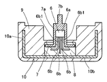
- the detection element 6 includes a main body 6a having a detection portion covered with a resin, and leads 6b extending from the main body 6a.
- the detection element 6 of the present embodiment includes three leads 6b.
- the lead 6b is divided into a main body side 6b1 and a front end side 6b2 with the bent portion as a boundary, and the main body side 6b1 of the lead 6b faces the rotation axis direction of the magnet 5 together with the main body 6a of the detection element 6.
- the leading end side 6b2 of the lead 6b is bent in a direction perpendicular to the rotation axis direction of the magnet 5.
- the leading end side 6b2 of the plurality of leads 6b is different from the leading end side 6b2 of the adjacent lead 6b with respect to the rotation axis direction of the magnet 5.
- the leading end side 6 b 2 of the central lead 6 b and the leading end side 6 b 2 of the two leads 6 b on both sides are the central leads with respect to the rotation axis direction of the magnet 5.
- the front end side 6b2 of 6b is provided at a position farther from the magnet 5 than the front end side 6b2 of the two leads 6b on both sides.
- the detection element 6 is disposed on the holder member 7, and the lead 6 b is electrically connected to the lead portion 13 b of the electronic component 13 and the conductive plate 14.
- the lead 6b is connected to the lead portion 13b and the conductive plate 14 by welding.
- the detection element 6 may be a detection element such as an MR element.
- the holder member 7 is made of a synthetic resin, for example, a synthetic resin such as polybutylene terephthalate (PBT).
- the holder member 7 has a columnar portion 7a provided with a support shaft portion 7b that rotatably supports the arm holder 4.
- the holder member 7 includes a frame body 7c that is formed to extend in a direction perpendicular to the central axis of the cylindrical portion 7a.
- the cylindrical part 7a of the holder member 7 is provided with a first holding part 7d formed of a concave part for holding the main body 6a of the detection element 6.
- the frame body 7c is provided with a second holding portion 7e that contacts and holds the lead 6b of the detection element 6.
- the second holding portion 7e is in contact with the distal end side 6b2 of each lead portion 6b of the detection element 6.
- a third holding portion 7f that holds the main body portion 13a of the electronic component 13 a fourth holding portion 7g that holds the lead portion 13b, a fifth holding portion 7h that holds the electrical connection member 11, A sixth holding portion 7 i that holds the conductive plate 14 is provided.
- the third holding portion 7f regulates the movement and inclination of the main body 13a of the electronic component 13 in the direction of the rotation axis of the magnet 5, and in the present embodiment, has a cup shape.
- the main body 13a of the electronic component 13 is accommodated in the cup shape.
- the shape of the third holding portion 7f is not limited to the cup shape, and any shape that restricts the movement and inclination of the magnet 5 of the main body portion 13a of the electronic component 13 in the rotation axis direction may be used.
- the fifth holding portion 7h is provided with a wall portion that abuts on the electrical connecting member 11 and sandwiches the electrical connecting member 11 from both sides, and holds the electrical connecting member 11.
- the sixth holding portion 7 i is in contact with and holding the conductive plate 14.
- the electronic component 13 is, for example, a capacitor or a diode, and is intended to reduce input / output noise of the detection element 6.
- the electronic component 13 is disposed on the side of the lead 6b with respect to the distal end side 6b2 of the lead 6b in which three detection elements 6 are arranged.
- the electronic component 13 includes a main body portion 13a and a lead portion 13b extending from the main body portion 13a.
- the electronic component 13 of this embodiment includes two lead portions 13b.
- the lead portion 13b is divided into a main body side 13b1 and a distal end side 13b2 with the bent portion as a boundary.
- the leading end side 13b2 of the lead portion 13b is bent in a direction perpendicular to the rotation axis direction of the magnet 5, and is bent in a direction perpendicular to the leading end side 6b2 of the lead 6b of the detection element 6. ing.
- the leading end side 13b2 of the plurality of lead portions 13b is different from the leading end side 13b2 of each lead portion 13b with respect to the rotation axis direction of the magnet 5.
- the leading end side 13 b 2 of one lead portion 13 b and the leading end side 13 b 2 of the other lead portion 13 b are one lead portion with respect to the rotation axis direction of the magnet 5.
- the leading end side 13b2 of 13b is provided at a position farther from the magnet 5 than the leading end side 13b2 of the other lead portion 13b.
- the lead part 13b of the electronic component 13 is electrically connected to the lead 6b of the detection element 6.
- the lead portion 13b is connected to the lead 6b by welding.
- the first case body 8 is made of a synthetic resin that can be molded at a low pressure, for example, a polyester-based synthetic resin.
- the detection element 6, a part of the holder member 7, a part of the electrical connection member 11, the electronic component 13, and the conductive plate 14 is covered by forming the first case body 8 by insert molding. A part of the cylindrical portion 7 a and the support shaft portion 7 b of the holder member 7 are exposed without being covered with the first case body 8.
- the second case body 9 is made of a synthetic resin, for example, a synthetic resin such as PBT or polyacetal (POM), and the first case body 8 except for a part of the columnar portion 7a and the support shaft portion 7b of the holder member 7. And the shield case 10 is covered.
- a synthetic resin for example, a synthetic resin such as PBT or polyacetal (POM)
- the holder member 7 and the second case body 9 are formed of the same material, for example, PBT, when the second case body 9 is formed, the holder member 7 and the second case body 9 are melted. The holder member 7 and the second case body 9 are bonded. Therefore, it is possible to prevent fuel or the like from entering the second case body 9 from the adhesion portion between the holder member 7 and the second case body 9.
- the thermal expansion coefficients of the first case body 8 and the second case body 9 are approximate and prevent peeling due to a temperature change.
- the shield case 10 protects the detection element 6 from an external magnetic field, and is made of, for example, an iron-nickel alloy and has a cup shape including a cylindrical portion 10a and a bottom portion 10b. A part of the cylindrical portion 10 a is provided with a notch portion 8 c for drawing the first case body 8 out of the shield case 10.
- the shield case 10 is covered with the second case body 9 in a state where the first case body 8 is housed in a recess formed by the cylindrical portion 10a and the bottom portion 10b.
- the shield case 10 is formed so as to accommodate a portion corresponding to the detection element 6 of the first case body 8.
- the shield case 10 can block the influence of magnetism from the outside of the liquid level detection device 1 and obtain a highly accurate detection output.
- the shield case 10 can be prevented from being deformed by covering the shield case 10 with the second case body 9. By preventing the deformation of the shield case 10, it is possible to prevent a change in magnetic characteristics. Furthermore, corrosion of the shield case 10 can be prevented. This is particularly effective when the fuel contains alcohol.
- the electrical connecting member 11 is a lead wire, and is composed of a conductor 11a having good conductivity such as copper and an insulating film 11b covering the conductor 11a.
- the conductor 11 a of the lead wire 11 is electrically connected to the conductive plate 14.
- the conductive plate 14 is made of a conductive metal, and electrically connects the lead 6b of the detection element 6 and the electrical connection member 11.
- the conductive plate 14, the lead 6b, and the electrical connection member 11 are electrically connected by welding.
- the conductive plates 14 on both sides are bent in a crank shape, and the leads 6 b are located at different positions with respect to the rotation axis direction of the magnet 5. This facilitates connection between the distal end side 6b2 and the three electrical connection members 11 aligned at the same position.
- the conductive plates 14 on both sides may be flat without being crank-shaped bent, and instead, the electrical connecting member 11 may be arranged differently with respect to the rotation axis direction of the magnet 5.
- the lead 6b of the detection element 6, the electrical connection member 11, the lead part 13b of the electronic component 13 and the conductive plate 14 are electrically connected to the holder member 7 by the detection element 6, the electrical connection member 11, the electronic component 13 and the conductive plate. 14 is arranged and welded to make an electrical connection.
- a liquid level detection device capable of achieving downsizing by electrically connecting the electronic component 13 to the rod-like lead 6b of the detection element 6 without using a plate-shaped terminal. 1 can be provided.
- the lead wire is used as the electrical connection member.
- the present invention is not limited to this embodiment.
- the present invention can be used in a liquid level detection device that detects the liquid level of various liquids in a tank.
Landscapes
- Physics & Mathematics (AREA)
- General Physics & Mathematics (AREA)
- Fluid Mechanics (AREA)
- Level Indicators Using A Float (AREA)
Abstract
Description
2 フロート
3 フロートアーム
5 マグネット
6 検出素子
6a 本体
6b リード
6b2 リード(先端側)
7 ホルダ部材
7d 第1保持部
7e 第2保持部
7f 第3保持部
7g 第4保持部
13 電子部品
13b リード部
13b1 リード部(本体部側)
13b2 リード部(先端側)
Claims (8)
- 液面の変位に追従作動するフロートを備えたフロートアームと、前記フロートアームの作動に伴って回動するマグネットと、前記マグネットの磁気変化を検出する検出素子と、前記検出素子と電気的に接続する電子部品とを、を備えた液面検出装置において、前記検出素子は本体と少なくとも3本のリードとを備え、前記複数のリードの先端側を隣り合う前記リードに対して前記マグネットの回動軸方向に対して異なる位置となるように折り曲げ、前記電子部品は本体部と2本のリード部とを備え、前記複数のリード部の先端側を互いに前記マグネットの回動軸方向に対して異なる位置となるように折り曲げ、前記検出素子の前記リードと前記電子部品の前記リード部とを電気的に接続したことを特徴とする液面検出装置。
- 前記リードと前記リード部とを溶接によって接続したことを特徴とする請求項1に記載の液面検出装置。
- 前記検出素子と前記電子部品とを保持するホルダ部材を設けたことを特徴とする請求項1に記載の液面検出装置。
- 前記ホルダ部材に前記検出素子の前記本体と前記リードとを保持する保持部を設けたことを特徴とする請求項3に記載の液面検出装置。
- 前記ホルダ部材に前記電子部品の前記本体部と前記リード部とを保持する保持部を設けたことを特徴とする請求項3に記載の液面検出装置。
- 前記リードの本体側を前記マグネットの回転軸方向に向けたことを特徴とする請求項1に記載の液面検出装置。
- 前記リード部の本体部側を前記マグネットの回転軸方向に向けたことを特徴とする請求項1に記載の液面検出装置。
- 前記3本のリードの前記先端側を並べ、前記リードの脇に前記電子部品を配設したことを特徴とする請求項1に記載の液面検出装置。
Priority Applications (3)
| Application Number | Priority Date | Filing Date | Title |
|---|---|---|---|
| US13/511,119 US20120266670A1 (en) | 2009-11-30 | 2010-11-10 | Liquid level detection device |
| CN2010800539360A CN102639976A (zh) | 2009-11-30 | 2010-11-10 | 液面检测装置 |
| EP10833070.5A EP2508852A4 (en) | 2009-11-30 | 2010-11-10 | DEVICE FOR DETERMINING THE FLUID LEVEL |
Applications Claiming Priority (2)
| Application Number | Priority Date | Filing Date | Title |
|---|---|---|---|
| JP2009270920A JP5403356B2 (ja) | 2009-11-30 | 2009-11-30 | 液面検出装置 |
| JP2009-270920 | 2009-11-30 |
Publications (1)
| Publication Number | Publication Date |
|---|---|
| WO2011065223A1 true WO2011065223A1 (ja) | 2011-06-03 |
Family
ID=44066326
Family Applications (1)
| Application Number | Title | Priority Date | Filing Date |
|---|---|---|---|
| PCT/JP2010/069979 Ceased WO2011065223A1 (ja) | 2009-11-30 | 2010-11-10 | 液面検出装置 |
Country Status (6)
| Country | Link |
|---|---|
| US (1) | US20120266670A1 (ja) |
| EP (1) | EP2508852A4 (ja) |
| JP (1) | JP5403356B2 (ja) |
| KR (1) | KR20120102632A (ja) |
| CN (1) | CN102639976A (ja) |
| WO (1) | WO2011065223A1 (ja) |
Cited By (1)
| Publication number | Priority date | Publication date | Assignee | Title |
|---|---|---|---|---|
| WO2014050498A1 (ja) * | 2012-09-28 | 2014-04-03 | 日本精機株式会社 | 液面検出装置、及び液面検出装置の製造方法 |
Families Citing this family (8)
| Publication number | Priority date | Publication date | Assignee | Title |
|---|---|---|---|---|
| JP5966607B2 (ja) * | 2012-05-18 | 2016-08-10 | 日本精機株式会社 | 液面検出装置 |
| JP6020010B2 (ja) * | 2012-09-28 | 2016-11-02 | 日本精機株式会社 | 液面検出装置、及び液面検出装置の製造方法 |
| CN103123414A (zh) | 2012-11-15 | 2013-05-29 | 玉晶光电(厦门)有限公司 | 一种可携式电子装置与其光学成像镜头 |
| JP6061137B2 (ja) * | 2013-01-21 | 2017-01-18 | 日本精機株式会社 | 液面検出装置 |
| JP5959453B2 (ja) * | 2013-02-27 | 2016-08-02 | 矢崎総業株式会社 | 液面レベルセンサ |
| JP5953253B2 (ja) * | 2013-03-14 | 2016-07-20 | 矢崎総業株式会社 | センサ及びセンサの製造方法 |
| JP6123578B2 (ja) * | 2013-08-27 | 2017-05-10 | 株式会社デンソー | 液面検出装置の製造方法 |
| JP6634201B2 (ja) * | 2014-03-17 | 2020-01-22 | 矢崎総業株式会社 | 液面レベルセンサ |
Citations (5)
| Publication number | Priority date | Publication date | Assignee | Title |
|---|---|---|---|---|
| JPS6362335A (ja) * | 1986-09-03 | 1988-03-18 | Nec Corp | 集積回路装置 |
| JPH10129785A (ja) * | 1996-10-29 | 1998-05-19 | Hitachi Ltd | 収納容器 |
| JP2004251780A (ja) | 2003-02-20 | 2004-09-09 | Yazaki Corp | 非接触式液面レベルセンサ及びその製造方法 |
| JP2008014917A (ja) * | 2005-10-21 | 2008-01-24 | Denso Corp | 液面検出装置とその製造方法 |
| JP2009243928A (ja) * | 2008-03-28 | 2009-10-22 | Yazaki Corp | 非接触式液面レベルセンサ |
Family Cites Families (3)
| Publication number | Priority date | Publication date | Assignee | Title |
|---|---|---|---|---|
| US3889365A (en) * | 1971-08-09 | 1975-06-17 | Gordon L Brock | Electronic module and method of fabricating same |
| JP3605097B2 (ja) * | 2002-07-02 | 2004-12-22 | 矢崎総業株式会社 | 非接触式液面レベルセンサ |
| DE102006049391B4 (de) * | 2005-10-21 | 2015-02-26 | Denso Corporation | Flüssigkeitspegelerfassungsvorrichtung und Verfahren zum Herstellen derselben |
-
2009
- 2009-11-30 JP JP2009270920A patent/JP5403356B2/ja not_active Expired - Fee Related
-
2010
- 2010-11-10 CN CN2010800539360A patent/CN102639976A/zh active Pending
- 2010-11-10 EP EP10833070.5A patent/EP2508852A4/en not_active Withdrawn
- 2010-11-10 KR KR1020127012380A patent/KR20120102632A/ko not_active Ceased
- 2010-11-10 US US13/511,119 patent/US20120266670A1/en not_active Abandoned
- 2010-11-10 WO PCT/JP2010/069979 patent/WO2011065223A1/ja not_active Ceased
Patent Citations (5)
| Publication number | Priority date | Publication date | Assignee | Title |
|---|---|---|---|---|
| JPS6362335A (ja) * | 1986-09-03 | 1988-03-18 | Nec Corp | 集積回路装置 |
| JPH10129785A (ja) * | 1996-10-29 | 1998-05-19 | Hitachi Ltd | 収納容器 |
| JP2004251780A (ja) | 2003-02-20 | 2004-09-09 | Yazaki Corp | 非接触式液面レベルセンサ及びその製造方法 |
| JP2008014917A (ja) * | 2005-10-21 | 2008-01-24 | Denso Corp | 液面検出装置とその製造方法 |
| JP2009243928A (ja) * | 2008-03-28 | 2009-10-22 | Yazaki Corp | 非接触式液面レベルセンサ |
Non-Patent Citations (1)
| Title |
|---|
| See also references of EP2508852A4 |
Cited By (1)
| Publication number | Priority date | Publication date | Assignee | Title |
|---|---|---|---|---|
| WO2014050498A1 (ja) * | 2012-09-28 | 2014-04-03 | 日本精機株式会社 | 液面検出装置、及び液面検出装置の製造方法 |
Also Published As
| Publication number | Publication date |
|---|---|
| EP2508852A4 (en) | 2016-10-05 |
| EP2508852A1 (en) | 2012-10-10 |
| CN102639976A (zh) | 2012-08-15 |
| KR20120102632A (ko) | 2012-09-18 |
| JP5403356B2 (ja) | 2014-01-29 |
| US20120266670A1 (en) | 2012-10-25 |
| JP2011112581A (ja) | 2011-06-09 |
Similar Documents
| Publication | Publication Date | Title |
|---|---|---|
| JP5403356B2 (ja) | 液面検出装置 | |
| JP5152679B2 (ja) | 液面検出装置 | |
| JP4085078B2 (ja) | 回転検出センサ | |
| US20120111108A1 (en) | Liquid level detecting device | |
| JP2013137256A (ja) | 液面検出装置 | |
| CN104272067A (zh) | 液面检测装置 | |
| JP2014163880A (ja) | 液面レベルセンサ | |
| CN105051501A (zh) | 传感器及传感器的制造方法 | |
| JP2011141146A (ja) | 液面検出装置とその製造方法 | |
| JP4720159B2 (ja) | 液面検出装置 | |
| JP2012233747A (ja) | 液面検出装置 | |
| JP2010175425A (ja) | 液面検出装置 | |
| WO2011070885A1 (ja) | 液面検出装置 | |
| JP2010271298A (ja) | 角度センサ及びこれを用いた回転角度検出装置 | |
| JP5019044B2 (ja) | 液面検出装置 | |
| JP2007240274A (ja) | 液面検出装置 | |
| JP4992690B2 (ja) | 磁気的位置検出装置 | |
| JP5119954B2 (ja) | 液面検出装置 | |
| JP2011133279A (ja) | 液面検出装置 | |
| JP2006153615A (ja) | 液面検出装置 | |
| WO2013108767A1 (ja) | 電流検出装置 | |
| JP5494084B2 (ja) | 液面検出装置の製造方法 | |
| JP3829331B2 (ja) | 角度検出器 | |
| JP2004332633A (ja) | スロットル制御装置 | |
| JP2011012967A (ja) | 移動物体検出装置 |
Legal Events
| Date | Code | Title | Description |
|---|---|---|---|
| WWE | Wipo information: entry into national phase |
Ref document number: 201080053936.0 Country of ref document: CN |
|
| 121 | Ep: the epo has been informed by wipo that ep was designated in this application |
Ref document number: 10833070 Country of ref document: EP Kind code of ref document: A1 |
|
| ENP | Entry into the national phase |
Ref document number: 20127012380 Country of ref document: KR Kind code of ref document: A |
|
| REEP | Request for entry into the european phase |
Ref document number: 2010833070 Country of ref document: EP |
|
| WWE | Wipo information: entry into national phase |
Ref document number: 2010833070 Country of ref document: EP |
|
| WWE | Wipo information: entry into national phase |
Ref document number: 13511119 Country of ref document: US |
|
| NENP | Non-entry into the national phase |
Ref country code: DE |