WO2011065314A1 - 光ファイバ被覆除去器 - Google Patents
光ファイバ被覆除去器 Download PDFInfo
- Publication number
- WO2011065314A1 WO2011065314A1 PCT/JP2010/070757 JP2010070757W WO2011065314A1 WO 2011065314 A1 WO2011065314 A1 WO 2011065314A1 JP 2010070757 W JP2010070757 W JP 2010070757W WO 2011065314 A1 WO2011065314 A1 WO 2011065314A1
- Authority
- WO
- WIPO (PCT)
- Prior art keywords
- optical fiber
- heater
- coating
- support member
- housing
- Prior art date
- Legal status (The legal status is an assumption and is not a legal conclusion. Google has not performed a legal analysis and makes no representation as to the accuracy of the status listed.)
- Ceased
Links
Images




Classifications
-
- G—PHYSICS
- G02—OPTICS
- G02B—OPTICAL ELEMENTS, SYSTEMS OR APPARATUS
- G02B6/00—Light guides; Structural details of arrangements comprising light guides and other optical elements, e.g. couplings
- G02B6/24—Coupling light guides
- G02B6/245—Removing protective coverings of light guides before coupling
-
- H—ELECTRICITY
- H02—GENERATION; CONVERSION OR DISTRIBUTION OF ELECTRIC POWER
- H02G—INSTALLATION OF ELECTRIC CABLES OR LINES, OR OF COMBINED OPTICAL AND ELECTRIC CABLES OR LINES
- H02G1/00—Methods or apparatus specially adapted for installing, maintaining, repairing or dismantling electric cables or lines
- H02G1/12—Methods or apparatus specially adapted for installing, maintaining, repairing or dismantling electric cables or lines for removing insulation or armouring from cables, e.g. from the end thereof
- H02G1/1202—Methods or apparatus specially adapted for installing, maintaining, repairing or dismantling electric cables or lines for removing insulation or armouring from cables, e.g. from the end thereof by cutting and withdrawing insulation
- H02G1/1204—Hand-held tools
- H02G1/1207—Hand-held tools the cutting element not rotating about the wire or cable
- H02G1/1209—Hand-held tools the cutting element not rotating about the wire or cable making a transverse cut
- H02G1/1212—Hand-held tools the cutting element not rotating about the wire or cable making a transverse cut using wire or cable clamping means
-
- H—ELECTRICITY
- H02—GENERATION; CONVERSION OR DISTRIBUTION OF ELECTRIC POWER
- H02G—INSTALLATION OF ELECTRIC CABLES OR LINES, OR OF COMBINED OPTICAL AND ELECTRIC CABLES OR LINES
- H02G1/00—Methods or apparatus specially adapted for installing, maintaining, repairing or dismantling electric cables or lines
- H02G1/12—Methods or apparatus specially adapted for installing, maintaining, repairing or dismantling electric cables or lines for removing insulation or armouring from cables, e.g. from the end thereof
- H02G1/1202—Methods or apparatus specially adapted for installing, maintaining, repairing or dismantling electric cables or lines for removing insulation or armouring from cables, e.g. from the end thereof by cutting and withdrawing insulation
- H02G1/1204—Hand-held tools
- H02G1/1221—Hand-held tools the cutting element rotating about the wire or cable
- H02G1/1224—Hand-held tools the cutting element rotating about the wire or cable making a transverse cut
-
- H—ELECTRICITY
- H02—GENERATION; CONVERSION OR DISTRIBUTION OF ELECTRIC POWER
- H02G—INSTALLATION OF ELECTRIC CABLES OR LINES, OR OF COMBINED OPTICAL AND ELECTRIC CABLES OR LINES
- H02G1/00—Methods or apparatus specially adapted for installing, maintaining, repairing or dismantling electric cables or lines
- H02G1/12—Methods or apparatus specially adapted for installing, maintaining, repairing or dismantling electric cables or lines for removing insulation or armouring from cables, e.g. from the end thereof
- H02G1/1202—Methods or apparatus specially adapted for installing, maintaining, repairing or dismantling electric cables or lines for removing insulation or armouring from cables, e.g. from the end thereof by cutting and withdrawing insulation
- H02G1/1204—Hand-held tools
- H02G1/1236—Features relating to cutting elements
- H02G1/1241—Features relating to cutting elements the cutting element being a stack of blades
-
- H—ELECTRICITY
- H02—GENERATION; CONVERSION OR DISTRIBUTION OF ELECTRIC POWER
- H02G—INSTALLATION OF ELECTRIC CABLES OR LINES, OR OF COMBINED OPTICAL AND ELECTRIC CABLES OR LINES
- H02G1/00—Methods or apparatus specially adapted for installing, maintaining, repairing or dismantling electric cables or lines
- H02G1/12—Methods or apparatus specially adapted for installing, maintaining, repairing or dismantling electric cables or lines for removing insulation or armouring from cables, e.g. from the end thereof
- H02G1/1275—Methods or apparatus specially adapted for installing, maintaining, repairing or dismantling electric cables or lines for removing insulation or armouring from cables, e.g. from the end thereof by applying heat
-
- B—PERFORMING OPERATIONS; TRANSPORTING
- B25—HAND TOOLS; PORTABLE POWER-DRIVEN TOOLS; MANIPULATORS
- B25B—TOOLS OR BENCH DEVICES NOT OTHERWISE PROVIDED FOR, FOR FASTENING, CONNECTING, DISENGAGING, OR HOLDING
- B25B7/00—Pliers; Other hand-held gripping tools with jaws on pivoted limbs; Details applicable generally to pivoted-limb hand tools
Definitions
- the present invention relates to an optical fiber sheath remover.
- Patent Document 1 Japanese Patent Application Laid-Open No. 2001-108836 (Patent Document 1) and Japanese Patent Application Laid-Open No. 11-337738 (Patent Document 2) disclose optical fiber coating removers used for such applications. These optical fiber sheath removers sandwich the end of a single-fiber or multiple-core optical fiber coated with resin with a remover body having a heater, and cover the end of the optical fiber core with a heater. Cut and extract while heating.
- An object of the present invention is to provide an optical fiber sheath remover that can perform a sheath removal operation with a small amount of power consumption without causing a failure due to intrusion of water and without causing breakage or damage of the optical fiber core wire. It is in.
- a sheath remover body and an optical fiber fixing portion provided so as to be able to contact with and separate from the sheath remover body.
- the sheath remover body includes a housing having a sheath remover, a sheath Includes a heater support member housed in a housing recess formed in the removal portion, a heater mounted on the heater support member, and a cutting blade attached to the sheath removal portion, and is held by the optical fiber fixing portion
- the coating near the end of the optical fiber core is cut with a cutting blade, and the end of the optical fiber is heated by a heater, and the optical fiber fixing part is separated from the coating remover main body, thereby
- An optical fiber sheath remover is provided that pulls the core glass fiber from the sheath.
- a space is formed between the housing recess and the heater support member, and the side surface of the heater support member and the inner surface of the housing recess are ribs formed in the heater support member or the housing recess. It is contacted through and seals the space.
- the housing has a substrate housing portion for housing the circuit board, and a partition wall between the coating removing portion and the substrate housing portion, and a part of the heater support member serves as the partition wall.
- the heater support member has a contact portion that contacts the partition wall and a relief portion that forms a gap with respect to the partition wall, and the coating removal unit and the substrate storage unit are liquid-tightly partitioned by the partition wall. It is preferable. It is preferable that a wall is erected at the bottom of the housing recess of the housing, and the heater support member is supported on the wall.
- the space is preferably partitioned liquid-tightly by the wall, and wiring connected to the heater is preferably accommodated in one of the spaces divided by the wall.
- the optical fiber sheath remover of the present invention it is possible to shorten the time required to raise the temperature to an optimum temperature for removing the sheath of the optical fiber core after energizing the heater, thereby realizing power saving. be able to.
- the tensile force required to remove the coating can be reduced, and the coating can be removed smoothly and smoothly without breaking or damaging the optical fiber core wire.
- an internal power supply When an internal power supply is used, its life can be prolonged, so that work can be performed for a long time, and work efficiency can be greatly improved.
- the optical fiber sheath remover is used outdoors, it is possible to prevent water from entering the space between the heater support member and the housing recess, and to eliminate problems caused by water intrusion. it can.
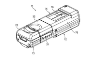
- FIG. 1 is a perspective view showing an embodiment of an optical fiber sheath remover according to the present invention.
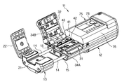
- FIG. 1 It is a perspective view which shows the state which opened the holder pressing lid and optical fiber pressing lid of the optical fiber coating removal machine of FIG.
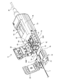
- FIG. 1 It is a perspective view which shows the state which set the fiber holder holding the optical fiber core wire to the optical fiber coating removal machine of FIG.
- FIG. 5 is a perspective view taken along line AA in FIG. 4.
- FIG. 5 is a diagram showing a part of the AA cross section in FIG. 4.
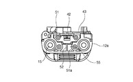
- FIG. 5 is a sectional view taken along line BB in FIG.
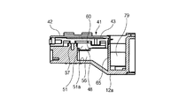
- FIG. 13 is an enlarged partial view of FIG. 12.
- FIG. 1 is a perspective view showing an optical fiber coating remover 11 according to an embodiment of the present invention.
- the optical fiber sheath remover 11 includes a sheath remover main body 12 and an optical fiber holder fixing portion (optical fiber fixing portion) 13 connected to one end side of the sheath remover main body 12.
- the sheath remover body 12 has a sheath removing portion 31 on one end side to which the optical fiber holder fixing portion 13 is connected, and a power source portion 75 on the other end side.
- An optical fiber pressing lid 32 is provided at the upper portion of the coating removing portion 31 so as to be freely opened and closed.
- the optical fiber holder fixing portion 13 is provided with a holder pressing lid 22 at its upper portion so as to be freely opened and closed.
- FIG. 2 is a perspective view showing a state in which the holder pressing cover 22 and the optical fiber pressing cover 32 of the optical fiber coating remover 11 are opened.
- the optical fiber holder fixing portion 13 is provided with two slide shafts 14 extending toward the sheath remover body 12, and the slide shafts 14 slide into the slide holes 15 of the sheath remover body 12. It is inserted as possible. Thereby, the optical fiber holder fixing
- the direction in which the optical fiber holder fixing portion 13 is separated from the sheath remover main body 12 is referred to as the front of the optical fiber sheath remover 11.
- a holder mounting portion 21 is formed on the upper surface of a portion exposed by opening the holder pressing lid 22 of the optical fiber holder fixing portion 13.
- Cutting blades 34 ⁇ / b> A and 34 ⁇ / b> B are respectively attached to the upper front surface of the portion exposed by opening the optical fiber pressing lid 32 in the coating removing section 31 and the front surface of the optical fiber pressing lid 32.
- the coating removal unit 31 includes an optical fiber core wire heating unit 41.
- the optical fiber heating unit 41 includes a plate heater 42 and a heater support member 43 on which the heater 42 is mounted.
- the sheath removing unit 31 is provided with a heater energization switch (not shown) that is turned on and off by opening and closing the optical fiber holding lid 32. When the optical fiber holding lid 32 is closed, the heater energization switch is turned on and power is supplied to the heater 42.
- the power supply unit 75 is provided with an operation unit 78 having various display LEDs such as a heater energization confirmation LED and a temperature display LED, and various switches such as a power switch and a temperature adjustment switch.
- a detachable lid 76 is provided around the operation unit 78 so as to cover the circuit board 77 (FIG. 5) that controls the supply of current to the heater 42.
- the power supply unit 75 can accommodate 4 to 8 1.2 to 1.5 volt batteries as internal power supplies.
- FIG. 3 is a perspective view showing a state in which the fiber holder 2 holding the optical fiber core wire 1 is set in the optical fiber sheath remover 11.
- the optical fiber core 1 is obtained by covering a glass fiber 1a with a coating 1b made of resin.
- the vicinity of the end of the optical fiber core wire 1 is held by the optical fiber holder 2, and the optical fiber holder 2 is placed on the holder mounting portion 21.
- the optical fiber holder 2 is held by the optical fiber holder fixing portion 13 by closing the holder pressing lid 22 while the optical fiber holder 2 is placed on the holder mounting portion 21. Further, by closing the optical fiber holding lid 32 with respect to the coating removing portion 31, only the coating 1b of the optical fiber core wire 1 is cut by the cutting blades 34A and 34B.
- the length of the coating removal target portion of the optical fiber core 1 can be determined.
- the power cord 81 can be inserted into and removed from the power source 75, and power can be supplied from an external power source by inserting the power cord 81.
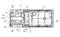
- FIG. 4 is a plan view of the sheath remover body 12 with the lid removed.
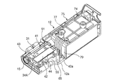
- FIG. 5 is a perspective view taken along the line AA in FIG.
- the optical fiber core heating part 41 is accommodated in an accommodation recess 51 formed in the sheath removal part 31 in the housing 12a constituting the sheath remover main body 12.
- a substrate storage portion 74 is provided below the lid 76 of the power supply portion 75, and a circuit substrate 77 that controls the supply of current to the heater 42 is stored in the substrate storage portion 74.
- a wiring housing recess 79 capable of housing the wiring 42 a connected to the heater 42 is formed on the coating removing portion 31 side of the power supply unit 75.
- the circuit board 77 and the wiring housing recess 79 are sealed by attaching the lid 76.
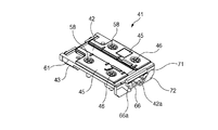
- FIG. 6 is a perspective view of the optical fiber heating section 41 as viewed from above
- FIG. 7 is a perspective view as viewed from below.
- a storage groove 44 (FIGS. 4 and 5) extending in the longitudinal direction is formed at the center in the left and right width direction, and the heater 42 is stored in the storage groove 44.
- a fixing member 45 is fixed by screws 46 on both sides of the storage groove 44, and the heater 42 is fixed to the heater support member 43 by the fixing member 45.
- U-shaped or U-shaped engagement ribs 47 and 48 are formed on the lower surface of the heater support member 43 at intervals in the longitudinal direction at the center position in the width direction.
- Side ribs 61 extending in the front-rear direction are formed on both side surfaces of the heater support member 43 in the left-right width direction. Further, the heater support member 43 has a rear end portion formed as a contact portion 71, and a relief portion 72 is formed below the contact portion 71. Furthermore, an engagement portion 66 having step portions 66a on both sides is formed at the rear end of the heater support member 43.
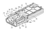
- FIG. 8 is a perspective view of the housing 12a constituting the sheath remover main body 12 as viewed from the front side
- FIG. 9 is a perspective view of the same as viewed from the rear side
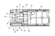
- FIG. 10 is a plan view of the housing 12a.
- the accommodation recess 51 is provided with a vertical wall (wall portion) 52 and a pair of vertical walls (wall portions) 53 extending in the axial direction of the sheath remover main body 12 at the bottom 51 a.
- the vertical wall 52 is formed on the front end side of the sheath remover main body 12, and the vertical wall 53 is formed on the rear end side of the vertical wall 52.
- the vertical wall 52 is disposed at the center in the width direction of the sheath remover main body 12, and the vertical wall 53 is disposed at a distance from the center of the sheath remover main body 12 in the width direction. Further, between the vertical wall 52 and the vertical wall 53, a vertical wall 52 and a horizontal wall (wall portion) 54 connected to the end of the vertical wall 53 are formed.
- the sheath remover body 12 is provided with a pair of partition walls 65 on the rear end side of the optical fiber core heating unit 41.
- the partition wall 65 is formed with two step portions 65a and 65b having different heights at the upper end.
- engaging recesses 59 and 60 are formed on the front end side and the rear end side of the vertical wall 52, respectively.
- FIG. 11 is a view showing a part of the AA cross section in FIG. 12 is a cross-sectional view taken along the line BB in FIG.
- the optical fiber heating unit 41 is accommodated in the accommodating recess 51 while being placed on the upper ends of the vertical walls 52 and 53 and the horizontal wall 54.
- a heat insulating space (space) 55 is formed between the heater support member 43 and the housing 12a.
- the space surrounded by the vertical wall 53 and the horizontal wall 54 is formed as a wiring space portion (space portion) 56.
- the wiring 42a connected to the heater 42 (FIGS. 4 and 5). Can be accommodated.
- the heat insulating space 55 and the wiring space 56 are liquid-tightly partitioned by the vertical wall 53 and the horizontal wall 54.
- female thread portions 57 are formed on both sides of the vertical wall 52 (FIGS. 8, 9, and 10), and the screw 58 is screwed to the female thread portion 57 so that the heater support member 43 is attached. It is fixed to the housing 12a.
- FIG. 13 is an enlarged partial view of FIG.
- the tips of the side ribs 61 formed on both side surfaces thereof contact the inner surface of the side wall 51b that forms the housing recess 51 of the housing 12a.
- the heat insulation space 55 and the wiring space 56 are sealed, and the heater support member 43 is positioned.
- the side ribs 61 are formed so as to be extremely thinner than the thickness of the side surface of the heater support member 43, and thereby the contact area of the heater support member 43 with the housing 12a is made as small as possible.
- FIG. 14 is an enlarged perspective view of the rear end side of the coating removal portion.
- the bottom portion of the engaging portion 66 of the heater support member 43 is placed on the step portion 65a of the partition wall 65, and the step portion 66a of the engaging portion 66 is placed on the step portion 65b of the partition wall 65, thereby supporting the heater.
- the rear end side of the member 43 is supported by the partition wall 65.
- the heater support member 43 is positioned with respect to the partition wall 65 by the contact portions 71 of the heater support member 43 coming into contact with the respective partition walls 65, and the heater support member 43 is formed at the location where the escape portion 72 of the heater support member 43 is formed.
- a gap is formed between the wall and the partition wall 65.
- the sheath removing portion 31 and the substrate housing portion 74 including the wiring housing recess 79 are partitioned liquid-tightly by the partition wall 65. Thereby, even when water enters from the vicinity of the coating removing unit 31, it is possible to prevent water from directly entering the substrate and the power supply unit. Furthermore, since the wiring housing recess 79 also serves as a liquid reservoir, it is possible to further prevent moisture from directly entering the substrate and the power supply unit. In addition, a drainage hole is provided near the bottom of the wiring housing recess 79, and a backflow prevention valve from the outside is provided in the hole, so that moisture entering the inside can be easily removed to the outside. It is also preferable.
- the optical fiber pressing lid 32 and the holder pressing lid 22 are opened, and the optical fiber holder 2 to which the optical fiber core wire 1 is attached is set on the holder mounting portion 21. Thereby, the front end side of the optical fiber core wire 1 is disposed on the heater 42.
- the holder pressing lid 22 is closed and the optical fiber pressing lid 32 is closed. Then, only the coating 1b of the optical fiber core wire 1 is cut by the two cutting blades 34A and 34B, and the heater energization switch is turned on by closing the optical fiber holding lid 32, and the heater 42 is energized. . Then, the coating 1b of the coating removal target portion of the optical fiber core 1 placed on the heater 42 is heated at high speed by the heater 42 and softens.
- the coating remover body 12 and the optical fiber holder fixing unit 13 are respectively gripped, and the optical fiber holder The fixing portion 13 is moved in a direction in which the fixing portion 13 is separated from the sheath remover body 12. In this way, only the coating 1b that has been heated and softened on the tip side with respect to the portion cut by the two cutting blades 34A and 34B is removed, and the glass fiber 1a is exposed at the end of the optical fiber core wire 1.
- the heater energization switch is turned off, the energization to the heater 42 is stopped, and unnecessary power consumption in the heater 42 during standby is prevented. .
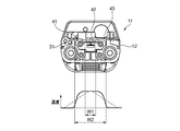
- FIG. 15 shows the temperature distribution in the width direction of the optical fiber core heating section 41 when the heater 42 is energized to generate heat.
- the heater support member 43 comes into contact with the housing 12a via the side ribs 61, and the contact area is reduced.
- the housing 12a and the heater support member The heat insulation space 55 and the wiring space 56 are formed between the heat insulation space portion 43 and the heat insulation layer, so that the heat of the heater 42 is not easily transmitted to the housing 12a side. Accordingly, heat transfer from the heater support member 43 (width W2) to the housing 12a is suppressed, and the entire width direction width (width W1) of the heater 42 becomes high as shown by a solid line in FIG.
- the coating removal target portion of the optical fiber core 1 placed on the heater 42 can be softened by raising its temperature extremely quickly and satisfactorily, and the end of the optical fiber core 1 can be smoothly and satisfactorily
- the coating 1b can be removed smoothly and the glass fiber 1a can be exposed.
- a space is not provided between the housing 12a and the heater support member 43, and the side ribs 61 are not formed on both side surfaces of the heater support member 43. Both side surfaces are largely brought into contact with the inner surface of the side wall 51 b of the housing recess 51 in the housing 12 a, and the heat of the heater 42 is transmitted to the housing 12 a side through the heater support member 43.
- the optical fiber core heating unit 41 only the central portion in the width direction of the heater 42 is hot, and the temperature is lowered around the periphery. Therefore, it takes time to sufficiently raise the temperature of the coating removal target portion of the optical fiber core 1 placed on the heater 42, and power consumption increases.
- the transmission of heat from the heater 42 to the housing 12a can be suppressed as much as possible. Therefore, it is possible to shorten the time required to raise the temperature to an optimum temperature for removing the coating 1b of the optical fiber core wire 1 after energizing the heater 42, thereby realizing power saving. Moreover, the pulling force required for the removal of the coating 1b can be reduced, and the removal operation of the coating 1b can be performed smoothly and smoothly without damage or damage to the optical fiber core wire 1.
- the life of the internal power supply can be extended, so that work can be performed for a long time and work efficiency can be greatly improved.
- the heat insulating space 55 and the wiring space 56 are sealed by contacting the side wall 51b of the housing recess 51 of the housing 12a via the side ribs 61 formed on both side surfaces of the heater support member 43, and the outside and the liquid. Even if the optical fiber sheath remover 11 is used outdoors, it is possible to prevent water from entering the heat insulating space 55 and the wiring space 56 because the optical fiber sheath remover 11 is used outdoors. The trouble due to can be eliminated.
- the contact portion 71 of the heater support member 43 is in contact with the partition wall 65 at the support portion of the heater support member 43 in the partition wall 65, and a clearance is formed with respect to the partition wall 65 in the escape portion 72 below the contact portion 71. Therefore, heat transfer from the support location in the partition wall 65 to the housing 12a can be suppressed as much as possible.
- the coating removal unit 31 and the substrate storage unit 74 are liquid-tightly partitioned by the partition wall 65, water enters from the coating removal unit 31 side to the substrate storage unit 74 side in which the circuit board 77 is stored. Can be reliably prevented, and the occurrence of problems due to water adhering to the circuit board 77 can be prevented.
- the housing support member 43 is provided from the lower side of the heater support member 43. Heat transfer to the body 12a can be suppressed as much as possible. Further, the lower side of the heater support member 43 by the vertical wall 52 and the horizontal wall 54 is formed into a heat insulating space 55 and a wiring space 56 that are liquid-tightly partitioned from each other, and the wiring 42 a connected to the heater 43 is accommodated in the wiring space 56. Therefore, even if water enters the heat insulating space 55, it is possible to prevent water from entering the wiring space 56 in which the wiring 42a is accommodated. Thereby, it is possible to prevent the occurrence of problems due to water adhering to the wiring 42 a connected to the heater 42.
- the side ribs 61 may be formed not on the heater support member 43 side but on the inner surface of the side wall 51b of the housing recess 51.
- the optical fiber sheath remover 11 includes a plurality of integrated optical fibers arranged in parallel. It can also be applied to an optical fiber core.
- JP 2001-108836 A Japanese Patent Laid-Open No. 11-337738
Landscapes
- Physics & Mathematics (AREA)
- General Physics & Mathematics (AREA)
- Optics & Photonics (AREA)
- Light Guides In General And Applications Therefor (AREA)
Abstract
Description
Claims (4)
- 被覆除去器本体と、前記被覆除去器本体に対して接離可能に設けられた光ファイバ固定部とを備え、前記被覆除去器本体は、被覆除去部を有する筐体と、前記被覆除去部に形成されている収納凹部に収納されているヒータ支持部材と、前記ヒータ支持部材に搭載されているヒータと、前記被覆除去部に取り付けられている切断刃とを含み、前記光ファイバ固定部に保持された光ファイバ心線の端部近傍における被覆を前記切断刃によって切断すると共に前記光ファイバ心線の端部を前記ヒータによって加熱した状態で前記光ファイバ固定部を前記被覆除去器本体から離間させることにより、前記光ファイバ心線のガラスファイバを前記被覆から引き抜く光ファイバ被覆除去器であって、
前記収容凹部と前記ヒータ支持部材との間には、空間部が形成され、
前記ヒータ支持部材の側面と前記収容凹部の内面とは、前記ヒータ支持部材または前記収容凹部に形成されたリブを介して接触されて前記空間部を封鎖している光ファイバ被覆除去器。 - 前記筐体は、回路基板を収納する基板収納部と、前記被覆除去部と前記基板収納部との間の隔壁とを有し、
前記ヒータ支持部材の一部が前記隔壁に支持され、前記ヒータ支持部材は、前記隔壁と接触する接触部と、前記隔壁に対して隙間を形成する逃げ部とを有し、前記被覆除去部と前記基板収納部とが、前記隔壁によって液密的に区画されている請求項1に記載の光ファイバ被覆除去器。 - 前記筐体の前記収容凹部の底部には、壁部が立設され、前記ヒータ支持部材は、前記壁部上に支持されている請求項1または2に記載の光ファイバ被覆除去器。
- 前記空間部は、前記壁部によって液密的に区画され、前記壁部によって分割された一方の空間部には、前記ヒータにつながる配線が収容される
請求項1から3の何れか一項に記載の光ファイバ被覆除去器。
Priority Applications (8)
| Application Number | Priority Date | Filing Date | Title |
|---|---|---|---|
| EP10833160.4A EP2506043A4 (en) | 2009-11-25 | 2010-11-22 | Optical fiber coating removal device |
| US13/511,487 US9075196B2 (en) | 2009-11-25 | 2010-11-22 | Optical fiber jacket remover |
| KR1020127013466A KR101386380B1 (ko) | 2009-11-25 | 2010-11-22 | 광파이버 피복 제거기 |
| AU2010323659A AU2010323659B2 (en) | 2009-11-25 | 2010-11-22 | Optical fiber coating removal device |
| CA2781768A CA2781768C (en) | 2009-11-25 | 2010-11-22 | Optical fiber jacket remover |
| CN201080052631.8A CN102667552B (zh) | 2009-11-25 | 2010-11-22 | 光纤护套去除器 |
| RU2012126069/28A RU2541372C9 (ru) | 2009-11-25 | 2010-11-22 | Устройство для удаления оболочки оптического волокна |
| HK13100677.5A HK1173502B (en) | 2009-11-25 | 2010-11-22 | Optical fiber jacket remover |
Applications Claiming Priority (2)
| Application Number | Priority Date | Filing Date | Title |
|---|---|---|---|
| JP2009-267928 | 2009-11-25 | ||
| JP2009267928A JP5166391B2 (ja) | 2009-11-25 | 2009-11-25 | 光ファイバ被覆除去器 |
Publications (1)
| Publication Number | Publication Date |
|---|---|
| WO2011065314A1 true WO2011065314A1 (ja) | 2011-06-03 |
Family
ID=44066419
Family Applications (1)
| Application Number | Title | Priority Date | Filing Date |
|---|---|---|---|
| PCT/JP2010/070757 Ceased WO2011065314A1 (ja) | 2009-11-25 | 2010-11-22 | 光ファイバ被覆除去器 |
Country Status (10)
| Country | Link |
|---|---|
| US (1) | US9075196B2 (ja) |
| EP (1) | EP2506043A4 (ja) |
| JP (1) | JP5166391B2 (ja) |
| KR (1) | KR101386380B1 (ja) |
| CN (1) | CN102667552B (ja) |
| AU (1) | AU2010323659B2 (ja) |
| CA (1) | CA2781768C (ja) |
| MY (1) | MY159712A (ja) |
| RU (1) | RU2541372C9 (ja) |
| WO (1) | WO2011065314A1 (ja) |
Cited By (1)
| Publication number | Priority date | Publication date | Assignee | Title |
|---|---|---|---|---|
| USD1105874S1 (en) | 2023-04-25 | 2025-12-16 | Sumitomo Electric Optifrontier Co., Ltd. | Optical fiber coating removal tool |
Families Citing this family (13)
| Publication number | Priority date | Publication date | Assignee | Title |
|---|---|---|---|---|
| JP2013195840A (ja) * | 2012-03-21 | 2013-09-30 | Asahi Glass Co Ltd | 光ファイバ切断・被覆材除去装置及び光ファイバ切断・被覆材除去方法 |
| WO2014019280A1 (zh) * | 2012-08-03 | 2014-02-06 | 大豪信息技术(威海)有限公司 | 热熔连接器剥刀工具 |
| USD745905S1 (en) * | 2013-10-11 | 2015-12-22 | Dh Infotech (Weihai) Inc. | Fiber thermal stripping device |
| MX2017003292A (es) * | 2014-10-02 | 2017-06-21 | 3M Innovative Properties Co | Herramienta de remocion de revestimiento de fibra optica desechable. |
| USD814897S1 (en) * | 2016-02-04 | 2018-04-10 | Knipex-Werk C. Gustav Putsch Kg | Stripper tool |
| CN105629382A (zh) * | 2016-02-17 | 2016-06-01 | 东莞市翔通光电技术有限公司 | 一种激光剥纤机及剥纤方法 |
| USD796926S1 (en) * | 2016-03-31 | 2017-09-12 | Inno Instrument (China) Inc. | Ribbon fiber optic thermal stripper |
| WO2018150595A1 (ja) | 2017-02-14 | 2018-08-23 | 株式会社フジクラ | 光ファイバ被覆除去装置、外部装置、光ファイバ被覆除去システム及び光ファイバ被覆除去方法 |
| CN114585954B (zh) * | 2019-11-26 | 2025-09-26 | 住友电工光学前沿株式会社 | 包覆层去除器 |
| JP7247149B2 (ja) * | 2020-08-07 | 2023-03-28 | 古河電気工業株式会社 | 被覆除去装置 |
| US11600972B2 (en) * | 2021-01-15 | 2023-03-07 | Raytheon Company | Embedded wire removal tool |
| CN115826131A (zh) * | 2022-12-27 | 2023-03-21 | 湖北光宏通信科技有限公司 | 一种表面嵌入光纤阵列装置 |
| CN117872547B (zh) * | 2024-03-13 | 2024-05-10 | 深圳市华电晨光智能科技有限公司 | 一种可调式智能高密度光纤配线单元 |
Citations (3)
| Publication number | Priority date | Publication date | Assignee | Title |
|---|---|---|---|---|
| JPH075327A (ja) * | 1993-06-15 | 1995-01-10 | Fujikura Ltd | テープファイバの被覆除去装置 |
| JPH11337738A (ja) | 1998-05-27 | 1999-12-10 | Sumitomo Electric Ind Ltd | 光ファイバ心線の被覆除去装置 |
| JP2001108836A (ja) | 1999-10-12 | 2001-04-20 | Hitachi Cable Ltd | 光ファイバ心線被覆除去器 |
Family Cites Families (11)
| Publication number | Priority date | Publication date | Assignee | Title |
|---|---|---|---|---|
| JP2951359B2 (ja) | 1989-04-20 | 1999-09-20 | 古河電気工業株式会社 | 光ファイバ用被覆除去装置 |
| SE515551C2 (sv) * | 1995-09-27 | 2001-08-27 | Ericsson Telefon Ab L M | Förfarande för att skala en kabel samt verktyg för avlägsnande av skyddshölje på kablar |
| JPH09113733A (ja) * | 1995-10-20 | 1997-05-02 | Fujikura Ltd | 光ファイバ心線の被覆除去装置用の電源供給構造、および被覆除去装置の使用方法 |
| US6023996A (en) * | 1997-10-23 | 2000-02-15 | Amherst International, Inc. | Optical fiber preparation unit |
| JP3844592B2 (ja) * | 1998-04-03 | 2006-11-15 | 株式会社フジクラ | 光ファイバの被覆除去装置 |
| JP2000019331A (ja) * | 1998-06-26 | 2000-01-21 | Sumitomo Electric Ind Ltd | 光ファイバ心線の被覆除去装置 |
| SE513172C2 (sv) * | 1998-07-03 | 2000-07-24 | Ericsson Telefon Ab L M | Förfarande och anordning för att avlägsna polymerbeläggning från en optisk fiber |
| JP2002328241A (ja) * | 2001-04-26 | 2002-11-15 | Fujikura Ltd | 光ファイバ被覆除去装置 |
| TW561657B (en) * | 2002-04-19 | 2003-11-11 | Ritek Corp | Device for peeling cladding layer of fiber ribbon |
| US7305169B2 (en) * | 2004-03-15 | 2007-12-04 | Sumitomo Electric Industries, Ltd. | Fiber cleaver |
| CN100403072C (zh) | 2004-03-15 | 2008-07-16 | 住友电气工业株式会社 | 纤维切割器 |
-
2009
- 2009-11-25 JP JP2009267928A patent/JP5166391B2/ja active Active
-
2010
- 2010-11-22 WO PCT/JP2010/070757 patent/WO2011065314A1/ja not_active Ceased
- 2010-11-22 CA CA2781768A patent/CA2781768C/en active Active
- 2010-11-22 KR KR1020127013466A patent/KR101386380B1/ko active Active
- 2010-11-22 EP EP10833160.4A patent/EP2506043A4/en not_active Withdrawn
- 2010-11-22 US US13/511,487 patent/US9075196B2/en active Active
- 2010-11-22 CN CN201080052631.8A patent/CN102667552B/zh active Active
- 2010-11-22 MY MYPI2012700306A patent/MY159712A/en unknown
- 2010-11-22 AU AU2010323659A patent/AU2010323659B2/en active Active
- 2010-11-22 RU RU2012126069/28A patent/RU2541372C9/ru active
Patent Citations (3)
| Publication number | Priority date | Publication date | Assignee | Title |
|---|---|---|---|---|
| JPH075327A (ja) * | 1993-06-15 | 1995-01-10 | Fujikura Ltd | テープファイバの被覆除去装置 |
| JPH11337738A (ja) | 1998-05-27 | 1999-12-10 | Sumitomo Electric Ind Ltd | 光ファイバ心線の被覆除去装置 |
| JP2001108836A (ja) | 1999-10-12 | 2001-04-20 | Hitachi Cable Ltd | 光ファイバ心線被覆除去器 |
Non-Patent Citations (1)
| Title |
|---|
| See also references of EP2506043A4 * |
Cited By (1)
| Publication number | Priority date | Publication date | Assignee | Title |
|---|---|---|---|---|
| USD1105874S1 (en) | 2023-04-25 | 2025-12-16 | Sumitomo Electric Optifrontier Co., Ltd. | Optical fiber coating removal tool |
Also Published As
| Publication number | Publication date |
|---|---|
| KR101386380B1 (ko) | 2014-04-16 |
| RU2541372C9 (ru) | 2015-06-10 |
| JP5166391B2 (ja) | 2013-03-21 |
| US20120279359A1 (en) | 2012-11-08 |
| EP2506043A4 (en) | 2018-02-28 |
| EP2506043A1 (en) | 2012-10-03 |
| US9075196B2 (en) | 2015-07-07 |
| RU2012126069A (ru) | 2013-12-27 |
| KR20120075486A (ko) | 2012-07-06 |
| CA2781768C (en) | 2017-09-12 |
| AU2010323659B2 (en) | 2013-12-12 |
| MY159712A (en) | 2017-01-13 |
| AU2010323659A1 (en) | 2012-06-07 |
| CN102667552B (zh) | 2014-03-12 |
| CN102667552A (zh) | 2012-09-12 |
| JP2011112791A (ja) | 2011-06-09 |
| CA2781768A1 (en) | 2011-06-03 |
| HK1173502A1 (en) | 2013-05-16 |
| RU2541372C2 (ru) | 2015-02-10 |
Similar Documents
| Publication | Publication Date | Title |
|---|---|---|
| JP5166391B2 (ja) | 光ファイバ被覆除去器 | |
| US6190057B1 (en) | Optical fiber ribbon fusion splicing apparatus | |
| KR100808689B1 (ko) | 광케이블 접속 단자함 | |
| JP2009198603A (ja) | 光終端装置 | |
| JP2018523172A (ja) | 自動ファイバストリップシステムおよび方法 | |
| JP2013195840A (ja) | 光ファイバ切断・被覆材除去装置及び光ファイバ切断・被覆材除去方法 | |
| JP4975540B2 (ja) | 光伝送モジュールおよび光伝送装置 | |
| HK1173502B (en) | Optical fiber jacket remover | |
| CN202600222U (zh) | 单芯光纤集成带状光纤的排纤装置 | |
| JP2008281817A5 (ja) | ||
| CN216816999U (zh) | 一种新型热剥机 | |
| KR101621809B1 (ko) | 광케이블 단자함 | |
| CN222561808U (zh) | 光纤热剥装置 | |
| KR101369454B1 (ko) | 주선 접속장치 및, 이를 포함하는 융착형 광 커넥터 | |
| KR200314261Y1 (ko) | 광케이블 피복 탈피장치 | |
| WO2018207732A1 (ja) | 光ファイバ被覆除去器 | |
| WO2018225678A1 (ja) | 光ファイバ被覆除去方法 | |
| WO2018225679A1 (ja) | 光ファイバ被覆除去器および光ファイバ被覆除去方法 | |
| JP4293554B2 (ja) | 光ファイバ端末処理用工具及びこれを用いた光ファイバ端末処理方法 | |
| JP2017151137A (ja) | 光モジュール、情報処理装置用基板およびそれを用いた情報処理装置 | |
| KR100904500B1 (ko) | 엘이디 채널 사인 | |
| GB2369196A (en) | Optical circuit housing containing resiliently deformable material or oval former | |
| CN103576247A (zh) | 光连接器 | |
| JPH11154791A (ja) | 電気機器の一括収納及び接続機構 |
Legal Events
| Date | Code | Title | Description |
|---|---|---|---|
| WWE | Wipo information: entry into national phase |
Ref document number: 201080052631.8 Country of ref document: CN |
|
| 121 | Ep: the epo has been informed by wipo that ep was designated in this application |
Ref document number: 10833160 Country of ref document: EP Kind code of ref document: A1 |
|
| WWE | Wipo information: entry into national phase |
Ref document number: 2010323659 Country of ref document: AU |
|
| WWE | Wipo information: entry into national phase |
Ref document number: 2010833160 Country of ref document: EP |
|
| WWE | Wipo information: entry into national phase |
Ref document number: 13511487 Country of ref document: US |
|
| ENP | Entry into the national phase |
Ref document number: 2781768 Country of ref document: CA Ref document number: 20127013466 Country of ref document: KR Kind code of ref document: A |
|
| WWE | Wipo information: entry into national phase |
Ref document number: 4619/DELNP/2012 Country of ref document: IN |
|
| NENP | Non-entry into the national phase |
Ref country code: DE |
|
| WWE | Wipo information: entry into national phase |
Ref document number: 1201002409 Country of ref document: TH |
|
| ENP | Entry into the national phase |
Ref document number: 2010323659 Country of ref document: AU Date of ref document: 20101122 Kind code of ref document: A |
|
| WWE | Wipo information: entry into national phase |
Ref document number: 2012126069 Country of ref document: RU |