WO2011065729A2 - Biocapteur - Google Patents
Biocapteur Download PDFInfo
- Publication number
- WO2011065729A2 WO2011065729A2 PCT/KR2010/008305 KR2010008305W WO2011065729A2 WO 2011065729 A2 WO2011065729 A2 WO 2011065729A2 KR 2010008305 W KR2010008305 W KR 2010008305W WO 2011065729 A2 WO2011065729 A2 WO 2011065729A2
- Authority
- WO
- WIPO (PCT)
- Prior art keywords
- channel
- blood
- biosensor
- introduction
- main body
- Prior art date
- Legal status (The legal status is an assumption and is not a legal conclusion. Google has not performed a legal analysis and makes no representation as to the accuracy of the status listed.)
- Ceased
Links
- HLIVGQVJCQRXFI-UHFFFAOYSA-N CC(C1C2)C3C1=C2CC3 Chemical compound CC(C1C2)C3C1=C2CC3 HLIVGQVJCQRXFI-UHFFFAOYSA-N 0.000 description 1
Images

Classifications
-
- B—PERFORMING OPERATIONS; TRANSPORTING
- B01—PHYSICAL OR CHEMICAL PROCESSES OR APPARATUS IN GENERAL
- B01L—CHEMICAL OR PHYSICAL LABORATORY APPARATUS FOR GENERAL USE
- B01L3/00—Containers or dishes for laboratory use, e.g. laboratory glassware; Droppers
- B01L3/50—Containers for the purpose of retaining a material to be analysed, e.g. test tubes
- B01L3/502—Containers for the purpose of retaining a material to be analysed, e.g. test tubes with fluid transport, e.g. in multi-compartment structures
- B01L3/5027—Containers for the purpose of retaining a material to be analysed, e.g. test tubes with fluid transport, e.g. in multi-compartment structures by integrated microfluidic structures, i.e. dimensions of channels and chambers are such that surface tension forces are important, e.g. lab-on-a-chip
- B01L3/502746—Containers for the purpose of retaining a material to be analysed, e.g. test tubes with fluid transport, e.g. in multi-compartment structures by integrated microfluidic structures, i.e. dimensions of channels and chambers are such that surface tension forces are important, e.g. lab-on-a-chip characterised by the means for controlling flow resistance, e.g. flow controllers, baffles or throttle valves
-
- G—PHYSICS
- G01—MEASURING; TESTING
- G01N—INVESTIGATING OR ANALYSING MATERIALS BY DETERMINING THEIR CHEMICAL OR PHYSICAL PROPERTIES
- G01N33/00—Investigating or analysing materials by specific methods not covered by groups G01N1/00 - G01N31/00
- G01N33/48—Biological material, e.g. blood, urine; Haemocytometers
- G01N33/483—Physical analysis of biological material
- G01N33/487—Physical analysis of biological material of liquid biological material
- G01N33/49—Blood
-
- C—CHEMISTRY; METALLURGY
- C12—BIOCHEMISTRY; BEER; SPIRITS; WINE; VINEGAR; MICROBIOLOGY; ENZYMOLOGY; MUTATION OR GENETIC ENGINEERING
- C12Q—MEASURING OR TESTING PROCESSES INVOLVING ENZYMES, NUCLEIC ACIDS OR MICROORGANISMS; COMPOSITIONS OR TEST PAPERS THEREFOR; PROCESSES OF PREPARING SUCH COMPOSITIONS; CONDITION-RESPONSIVE CONTROL IN MICROBIOLOGICAL OR ENZYMOLOGICAL PROCESSES
- C12Q1/00—Measuring or testing processes involving enzymes, nucleic acids or microorganisms; Compositions therefor; Processes of preparing such compositions
- C12Q1/02—Measuring or testing processes involving enzymes, nucleic acids or microorganisms; Compositions therefor; Processes of preparing such compositions involving viable microorganisms
- C12Q1/24—Methods of sampling, or inoculating or spreading a sample; Methods of physically isolating an intact microorganisms
-
- G—PHYSICS
- G01—MEASURING; TESTING
- G01N—INVESTIGATING OR ANALYSING MATERIALS BY DETERMINING THEIR CHEMICAL OR PHYSICAL PROPERTIES
- G01N33/00—Investigating or analysing materials by specific methods not covered by groups G01N1/00 - G01N31/00
- G01N33/48—Biological material, e.g. blood, urine; Haemocytometers
- G01N33/50—Chemical analysis of biological material, e.g. blood, urine; Testing involving biospecific ligand binding methods; Immunological testing
- G01N33/5005—Chemical analysis of biological material, e.g. blood, urine; Testing involving biospecific ligand binding methods; Immunological testing involving human or animal cells
- G01N33/5094—Chemical analysis of biological material, e.g. blood, urine; Testing involving biospecific ligand binding methods; Immunological testing involving human or animal cells for blood cell populations
-
- B—PERFORMING OPERATIONS; TRANSPORTING
- B01—PHYSICAL OR CHEMICAL PROCESSES OR APPARATUS IN GENERAL
- B01L—CHEMICAL OR PHYSICAL LABORATORY APPARATUS FOR GENERAL USE
- B01L2300/00—Additional constructional details
- B01L2300/06—Auxiliary integrated devices, integrated components
- B01L2300/0627—Sensor or part of a sensor is integrated
- B01L2300/0645—Electrodes
-
- B—PERFORMING OPERATIONS; TRANSPORTING
- B01—PHYSICAL OR CHEMICAL PROCESSES OR APPARATUS IN GENERAL
- B01L—CHEMICAL OR PHYSICAL LABORATORY APPARATUS FOR GENERAL USE
- B01L2300/00—Additional constructional details
- B01L2300/08—Geometry, shape and general structure
- B01L2300/0809—Geometry, shape and general structure rectangular shaped
- B01L2300/0825—Test strips
-
- B—PERFORMING OPERATIONS; TRANSPORTING
- B01—PHYSICAL OR CHEMICAL PROCESSES OR APPARATUS IN GENERAL
- B01L—CHEMICAL OR PHYSICAL LABORATORY APPARATUS FOR GENERAL USE
- B01L2300/00—Additional constructional details
- B01L2300/08—Geometry, shape and general structure
- B01L2300/0887—Laminated structure
-
- B—PERFORMING OPERATIONS; TRANSPORTING
- B01—PHYSICAL OR CHEMICAL PROCESSES OR APPARATUS IN GENERAL
- B01L—CHEMICAL OR PHYSICAL LABORATORY APPARATUS FOR GENERAL USE
- B01L2400/00—Moving or stopping fluids
- B01L2400/04—Moving fluids with specific forces or mechanical means
- B01L2400/0403—Moving fluids with specific forces or mechanical means specific forces
- B01L2400/0406—Moving fluids with specific forces or mechanical means specific forces capillary forces
-
- B—PERFORMING OPERATIONS; TRANSPORTING
- B01—PHYSICAL OR CHEMICAL PROCESSES OR APPARATUS IN GENERAL
- B01L—CHEMICAL OR PHYSICAL LABORATORY APPARATUS FOR GENERAL USE
- B01L3/00—Containers or dishes for laboratory use, e.g. laboratory glassware; Droppers
- B01L3/50—Containers for the purpose of retaining a material to be analysed, e.g. test tubes
- B01L3/502—Containers for the purpose of retaining a material to be analysed, e.g. test tubes with fluid transport, e.g. in multi-compartment structures
- B01L3/5027—Containers for the purpose of retaining a material to be analysed, e.g. test tubes with fluid transport, e.g. in multi-compartment structures by integrated microfluidic structures, i.e. dimensions of channels and chambers are such that surface tension forces are important, e.g. lab-on-a-chip
- B01L3/502707—Containers for the purpose of retaining a material to be analysed, e.g. test tubes with fluid transport, e.g. in multi-compartment structures by integrated microfluidic structures, i.e. dimensions of channels and chambers are such that surface tension forces are important, e.g. lab-on-a-chip characterised by the manufacture of the container or its components
Definitions
- the present invention relates to a biosensor, and more particularly, to a biosensor having increased manufacturing reproducibility by limiting a size of a microchannel separating blood cells in the width direction.
- POCT point of care testing
- biochip companies are conducting research.
- the need for rapid testing is increasing at the time of the occurrence of various new virus diseases, and thus the market demand for a mechanism for simple separation of blood cells and blood from whole blood in a short time. It is also increasing.
- the simplest way to separate blood cells and hepatocytes from whole blood is to install a filler in the channel through which whole blood flows to separate red blood cells and white blood cells by controlling the hydrodynamic resistance and fluid flow of whole blood in the channel. .
- the method only shows the possibility that blood cells present in whole blood can be separated when the filler is installed in the channel, and the complete separation is not shown due to the limitation of the filler configuration.
- the method may include Korean Patent No. 841856 as shown in FIG. 1.
- the patent is a structure that separates blood cells and plasma from whole blood through a gap from the submicro to nanometer (the vertical height of the channel), and is characterized in that the plasma and blood cells are separated by force without using the capillary phenomenon of the gap. .
- the senor illustrated in FIG. 1 has a jaw in a channel through which whole blood flows, and thus it is not easy to manufacture the sensor accurately in a structure in which microscale and macroscale are mixed.
- FIG. 2 is a schematic representation of the actual multi-sided formation of a device fabricated with a target gap of 0.6 ⁇ m on the top plate of a glass wafer and the bottom plate of a silicon wafer.
- the shape of the cross section, particularly the lower surface is very irregular, and in the dicing process in which the cross-sectional state of the channel is the last process, debris of silicon and glass flows into the channel and thus may not be properly cleaned, thereby acting as a resistance in the channel.
- the fragments act as a binding material between the upper plate and the lower plate forming the channel, the channel is not formed properly.
- the present invention provides a biosensor comprising a main body and an upper substrate bonded to an upper end of the main body, wherein the blood is formed on the upper surface of the main body; A channel formed on an upper surface of the main body and communicating with one side of the introduction means; And a discharging means formed on the upper surface of the main body and communicating with the other side of the channel and discharging air into the channel for the blood movement to the outside, wherein the channel has a minimum width in some sections.
- the width is 0.5 ⁇ m or more and 1 ⁇ m or less, and the height of the channel is 10 times the minimum width.
- the channel is characterized in that a single width.
- the introduction means is a first side of the channel, and the discharge means is a second side of the channel.
- the introduction means is a blood introduction portion formed on the upper surface of the body, the discharge means is a second side surface of the channel, the upper substrate is characterized in that the introduction hole is formed in a position corresponding to the blood introduction portion.
- the introduction means is a blood introduction portion formed on the upper surface of the body
- the discharge means is a blood storage portion formed on the upper surface of the body
- the upper substrate has an introduction hole and the blood storage portion at a position corresponding to the blood introduction portion.
- the discharge hole is formed in a position corresponding to the.
- the channel may include a first channel portion having a nozzle shape and a second channel portion having a single width.
- the present invention through the above-described problem solving means is limited to the width of the microchannel to the size for capillary action and blood cell separation, and further limited to the height 10 times the width of the channel, the production of the entire biosensor only by sub-micro level process Since it is possible to produce high reproducibility, and also to form the channel in the form of a nozzle rather than a single width, there is an effect to improve the efficiency of blood separation.
- FIG. 1 is a perspective view illustrating a conventional biosensor.
- FIG. 2A, 2B, and 3C are schematic views illustrating the cross-sectional shape of the biosensor of FIG. 1 after fabrication.
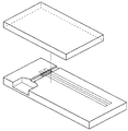
- FIG. 3 is an exploded perspective view showing an embodiment of a biosensor according to the present invention.
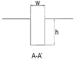
- FIG. 4 is a cross-sectional view of A-A of the biosensor of FIG. 3.
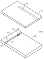
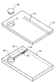
- FIG. 5 is an exploded perspective view showing another embodiment of the biosensor according to the present invention.
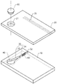
- FIG. 6 is an exploded perspective view showing another embodiment of the biosensor according to the present invention.
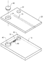
- FIG. 7 is an exploded perspective view showing another embodiment of the biosensor according to the present invention.
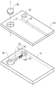
- FIG. 8 is an exploded perspective view showing another embodiment of the biosensor according to the present invention.
- FIG. 9 is an exploded perspective view showing another embodiment of the biosensor according to the present invention.
- FIG. 3 shows a first embodiment of the present invention.
- the biosensor 100 includes a sensor main body 10 and an upper substrate 20, and a channel 30 through which the injected blood is separated is formed in the main body, and the upper substrate 20 is the upper substrate 20. It is coupled to the upper surface of the body (10).
- the channel 30 is formed as a groove from the first side 31 of the main body 10 to the opposite second side 32.
- the channel 30 has three surfaces formed by the main body 10 and the upper surface of the upper substrate 20 forms the remaining surfaces. .
- the blood is introduced from the first side 31 of the channel 30 as the inflow means, and the second side 32 as the discharge means for smooth movement of the blood serves as a through hole of the channel 30.
- FIG. 1 A-A cross section of the channel 30 is shown in FIG.
- one of the width and height of the channel 30 should be 1 ⁇ m or less, so the width of the channel 30 is limited to 0.5 ⁇ m or more and 1 ⁇ m or less for the manufacturing process. It was.
- the width is 1 ⁇ m or more, blood cells cannot be separated from the blood, and when 0.5 ⁇ m or less, it is difficult to produce the sub micro level, resulting in a rapid drop in productivity.
- And h is preferably limited to 10 ⁇ w for fine groove processing by fine processing.
- the aspect ratio (h / w ratio) is 10 or more, since it is difficult to process in a general lithography process, and develop a separate process applied to the rapid drop in mass productivity.
- the width of the grooves is formed in an accurate shape, but the height of the grooves is difficult to form as designed by the processing by-products.
- the height of the channel 30 is limited to 1 ⁇ m or less and manufactured by fine processing, there is a disadvantage in that the height is not properly formed by processing by-products, but the biosensor 100 of the present invention has a width of 0.5 ⁇ m or more.
- the grooves formed by limiting the cross section of the grooves by any processing by-products are limited to 1 ⁇ m or less and 5 ⁇ m or more and 10 ⁇ m or less in height, which serves as a basic channel 30.
- the channel 30 may be formed in a curved shape as needed, and the width of the channel may vary in the length direction, but at least some sections of the channel may have a width of 0.5 ⁇ m or more and 1 ⁇ m or less to separate blood cells. .
- the channel 30 may be formed of a plurality of independent grooves, respectively, as necessary.
- the channel 30 may have a plurality of grooves formed on the first side surface 31 as needed, and each of the grooves may be joined to the center portion so that one groove passes through the second side surface at the end thereof. .
- the plasma separated by the biosensor 100 may be measured by an electrochemical or spectroscopic method through a biochemical reaction or a chemical reaction including an enzymatic reaction or an immunological reaction.
- the materials of the body 10 and the upper substrate 20 are made transparent.
- the material is transparent polymer or transparent glass.
- the biosensor 100 has an enzyme 60 seated on the channel 30 for electrochemical measurement, and an electromotive force formed by the reaction of the enzyme 60 and plasma on the lower surface of the upper substrate 20.
- An electrode 70 for measuring can be formed.
- the electrode 70 serves to provide an electromotive force generated by being connected to a measuring device (not shown) to the measuring device.
- the channel 30 of the biosensor of the present invention may be configured in two different forms.
- the first channel portion 33 is in the form of a nozzle in the direction of blood movement, and the second channel portion 34 is generally in the form of a groove having a constant width.
- the first channel part 33 has a width that narrows in the fluid moving direction, thereby increasing the fluid flow rate.
- the plasma of the channel 30 is separated by the second channel portion 34.
- the inflow means of the biosensor may have a wider first side 31 than in the embodiment of FIG. 3 to increase the inflow amount of blood.
- the width of the second channel part 34 is 0.5 ⁇ m or more and 1 ⁇ m or less, and the height of the entire channel 30 is 5 ⁇ m or more and 10 ⁇ m or less.
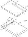
- FIGS 6 and 7 show an embodiment in which the inlet means for the inflow of blood is configured on the upper surface of the biosensor 100.
- the blood of the biosensor 100 is placed in the blood introduction portion 40, the plasma is separated into the channel 30 by the capillary action of the channel 30, the discharge means is the second side (32).
- An introduction hole 21 having the same size as the blood introduction portion 40 is formed in the upper substrate 20 of the biosensor 100, and the introduction hole 21 has a rubber stopper 80 for promoting blood movement. Is fitted.
- the rubber stopper 80 closes the introduction hole 21 and presses the rubber stopper 80 to accelerate the movement of the blood by the pressing force, thereby providing rapid blood separation.
- the enzyme 60 and the electrode 70 may be formed on the lower surface of the channel 30 and the upper substrate 20, respectively, to perform electrochemical measurements.
- the entire biosensor 100 may be formed of a transparent material for optical measurement.
- the enzyme 60 and the electrode 70 may be omitted.
- the channel 30 may be configured to have a single groove as shown in FIG. 6, and may be configured as shown in FIG. 7 if necessary.
- the channel 10 shown in FIG. 7 has a first channel portion 33 in contact with the blood introduction portion 40 in the form of a nozzle, and the second channel portion 34 in communication with the second end surface has a single width.
- the flow of blood is accelerated by the nozzle effect on the first channel portion 33 and the actual plasma separation is performed in the second channel portion 34.
- the channel 30 has a width of the second channel portion 34 having a minimum width of 0.5 ⁇ m or more and 1 ⁇ m or less and a height of 5 ⁇ m or more and 10 ⁇ m or less, which is 10 times the width.
- a separate blood storage unit 50 may be formed in the main body.
- the discharge hole 22 is formed at the same size and the same position as the blood storage unit 50 in the upper substrate 20.
- the enzyme may be located in the blood storage unit 50, and the electrode may be formed on the upper surface of the main body 10, and the channel 30 may be formed on the lower surface of the upper substrate 20. ) To position the enzyme 60 and avoid the discharge hole 22 to form the electrode 70 on the lower surface of the upper substrate 20.
- the channel 30 may have a constant width, and as shown in FIG. 9, the first channel portion 33 having a nozzle shape and the second channel portion having a single width ( 34) can be configured.
- a plurality of channels 30 may be configured to connect the blood introduction part 40 and the blood storage part 50.
- the blood introduction part 40 and the blood storage part 50 are formed on the upper surface of the main body 10 at the same height as the height of the channel 30.
- the manufacturing of the main body 10 is possible only by the process of micro-scale during manufacture, and thus has high manufacturing efficiency.
- all the channels 30 of the above embodiments may be treated with various hydrophilic materials on the surface to control the inflow rate of blood and plasma, or may be mechanically treated with a plasma treatment or a micropattern.
Landscapes
- Health & Medical Sciences (AREA)
- Life Sciences & Earth Sciences (AREA)
- Chemical & Material Sciences (AREA)
- Engineering & Computer Science (AREA)
- Immunology (AREA)
- Organic Chemistry (AREA)
- Biomedical Technology (AREA)
- Analytical Chemistry (AREA)
- General Health & Medical Sciences (AREA)
- Hematology (AREA)
- Molecular Biology (AREA)
- Physics & Mathematics (AREA)
- Pathology (AREA)
- Proteomics, Peptides & Aminoacids (AREA)
- Wood Science & Technology (AREA)
- Zoology (AREA)
- Biochemistry (AREA)
- Microbiology (AREA)
- Biotechnology (AREA)
- Biophysics (AREA)
- Urology & Nephrology (AREA)
- Ecology (AREA)
- Medicinal Chemistry (AREA)
- General Engineering & Computer Science (AREA)
- Genetics & Genomics (AREA)
- Cell Biology (AREA)
- General Physics & Mathematics (AREA)
- Bioinformatics & Cheminformatics (AREA)
- Food Science & Technology (AREA)
- Chemical Kinetics & Catalysis (AREA)
- Dispersion Chemistry (AREA)
- Tropical Medicine & Parasitology (AREA)
- Clinical Laboratory Science (AREA)
- Investigating Or Analysing Biological Materials (AREA)
- Apparatus Associated With Microorganisms And Enzymes (AREA)
Abstract
La présente invention concerne un biocapteur et, plus particulièrement, un biocapteur dont la reproducibilité en production est améliorée par la réduction de la taille, dans le sens de la largeur, d'un microcanal servant à séparer les cellules sanguines. Pour obtenir ce résultat, un biocapteur est mis en œuvre, qui intègre un corps principal et une plaque supérieure fixée au bord supérieur du corps principal. Le biocapteur comprend: un moyen d'introduction pour introduire le sang formée sur la surface supérieure du corps principal; un canal formé sur la surface supérieure du corps principal et dont un bout se raccorde au moyen d'introduction; et un moyen d'évacuation formé sur la surface supérieure du corps principal et qui se raccorde à l'autre bout du canal et évacue vers l'extérieur l'air présent à l'intérieur du canal pour assurer le mouvement du sang. Le canal présente une section d'une largeur minimale d'au moins 0,5 μm et d'au plus 1 μm, et sa hauteur fait 10 fois la largeur minimale.
Applications Claiming Priority (2)
| Application Number | Priority Date | Filing Date | Title |
|---|---|---|---|
| KR1020090114851A KR101004989B1 (ko) | 2009-11-25 | 2009-11-25 | 바이오 센서 |
| KR10-2009-0114851 | 2009-11-25 |
Publications (2)
| Publication Number | Publication Date |
|---|---|
| WO2011065729A2 true WO2011065729A2 (fr) | 2011-06-03 |
| WO2011065729A3 WO2011065729A3 (fr) | 2011-10-27 |
Family
ID=43513508
Family Applications (1)
| Application Number | Title | Priority Date | Filing Date |
|---|---|---|---|
| PCT/KR2010/008305 Ceased WO2011065729A2 (fr) | 2009-11-25 | 2010-11-23 | Biocapteur |
Country Status (2)
| Country | Link |
|---|---|
| KR (1) | KR101004989B1 (fr) |
| WO (1) | WO2011065729A2 (fr) |
Cited By (1)
| Publication number | Priority date | Publication date | Assignee | Title |
|---|---|---|---|---|
| WO2020261086A1 (fr) * | 2019-06-28 | 2020-12-30 | 3M Innovative Properties Company | Articles comportant des couches d'enrobage et leurs procédés de fabrication |
Families Citing this family (3)
| Publication number | Priority date | Publication date | Assignee | Title |
|---|---|---|---|---|
| KR101429253B1 (ko) * | 2014-05-22 | 2014-08-12 | (주) 굿모닝 바이오 | 다채널 혈액 통로를 구비한 혈소판 활성화 장치 |
| KR101706750B1 (ko) * | 2015-08-19 | 2017-02-14 | 전남대학교산학협력단 | 다중채널 세포배양용기 |
| KR101879500B1 (ko) * | 2016-08-01 | 2018-07-19 | 한국기계연구원 | 회수형 미세유체소자 |
Family Cites Families (4)
| Publication number | Priority date | Publication date | Assignee | Title |
|---|---|---|---|---|
| JP4504289B2 (ja) * | 2004-09-27 | 2010-07-14 | シチズンホールディングス株式会社 | バイオセンサ |
| JP4693657B2 (ja) | 2005-03-29 | 2011-06-01 | シチズンホールディングス株式会社 | バイオセンサ |
| KR100841355B1 (ko) | 2006-04-04 | 2008-07-01 | 주식회사 올메디쿠스 | 무동력 혈액분리수단을 구비한 바이오센서 칩 |
| KR100735898B1 (ko) | 2006-08-25 | 2007-07-04 | 한국기계연구원 | 휴대용 미세 혈액 분리기 |
-
2009
- 2009-11-25 KR KR1020090114851A patent/KR101004989B1/ko not_active Expired - Fee Related
-
2010
- 2010-11-23 WO PCT/KR2010/008305 patent/WO2011065729A2/fr not_active Ceased
Cited By (4)
| Publication number | Priority date | Publication date | Assignee | Title |
|---|---|---|---|---|
| WO2020261086A1 (fr) * | 2019-06-28 | 2020-12-30 | 3M Innovative Properties Company | Articles comportant des couches d'enrobage et leurs procédés de fabrication |
| CN114302808A (zh) * | 2019-06-28 | 2022-04-08 | 3M创新有限公司 | 具有共形层的制品及其制造方法 |
| CN114302808B (zh) * | 2019-06-28 | 2024-05-03 | 舒万诺知识产权公司 | 具有共形层的制品及其制造方法 |
| US12594554B2 (en) | 2019-06-28 | 2026-04-07 | Solventum Intellectual Properties Company | Articles having conformal layers and methods of making same |
Also Published As
| Publication number | Publication date |
|---|---|
| WO2011065729A3 (fr) | 2011-10-27 |
| KR101004989B1 (ko) | 2010-12-29 |
Similar Documents
| Publication | Publication Date | Title |
|---|---|---|
| US10500526B1 (en) | Method and device for high-throughput solution exchange for cell and particle suspensions | |
| JP4931330B2 (ja) | マイクロ流体構造、特にバイオチップを製造する方法および該方法によって得られた構造 | |
| KR101125060B1 (ko) | 입자를 포획하는 미세유체 소자 및 이를 이용한 입자 포획 방법 | |
| US20080213821A1 (en) | Microfluidic Cell Sorter System | |
| WO2017131452A1 (fr) | Appareil de séparation de particules et procédé de séparation de particules | |
| CN107497503B (zh) | 用于研究肿瘤单细胞侵袭和上皮间质转化的微流控芯片 | |
| US10300479B2 (en) | Tip overlay for continuous flow spotting apparatus | |
| CN101523222A (zh) | 微量分析测定装置及使用该装置的微量分析测定方法 | |
| TW200909338A (en) | Autonomous microfluidic apparatus | |
| WO2011065729A2 (fr) | Biocapteur | |
| US20140348706A1 (en) | Microfluidic Device and Microfluidic System | |
| WO2004072642A1 (fr) | Dispositif d'application de micro-echantillon et reaction d'une puce a adn et procede correspondant | |
| Yun et al. | A microfluidic chip for measurement of biomolecules using a microbead-based quantum dot fluorescence assay | |
| CN105203375B (zh) | 一种高通量的血浆分离器件及其制备方法 | |
| WO2015008927A1 (fr) | Puce de biocapteur | |
| JPWO2004008132A1 (ja) | 生体分子分離セル及びその製造方法並びにdna分取装置 | |
| CN111229336B (zh) | 光波导多微流道芯片的制造方法 | |
| CN211785572U (zh) | 光波导微流体检测系统 | |
| KR20140073051A (ko) | 미세 채널을 이용한 세포 분리 장치 | |
| CN115786104B (zh) | 一种基于双侧进样的高通量双凹形捕获配对结构阵列的细胞电融合芯片装置及制备方法 | |
| Nam | 200 mm wafer-scale fabrication of polydimethylsiloxane fluidic devices for fluorescence imaging of single DNA molecules | |
| KR100788458B1 (ko) | 유체영동기반 세포분리용 미세유체칩 및 이를 이용한혈액분리방법 | |
| CN211826081U (zh) | 光波导多微流道检测系统 | |
| KR20050010423A (ko) | 미세유체채널이 집적화된 3차원 전극시스템 및 그 제작 방법 | |
| CN211877769U (zh) | 光栅波导多微流道检测系统 |
Legal Events
| Date | Code | Title | Description |
|---|---|---|---|
| 121 | Ep: the epo has been informed by wipo that ep was designated in this application |
Ref document number: 10833541 Country of ref document: EP Kind code of ref document: A1 |
|
| NENP | Non-entry into the national phase |
Ref country code: DE |
|
| 32PN | Ep: public notification in the ep bulletin as address of the adressee cannot be established |
Free format text: NOTING OF LOSS OF RIGHTS PURSUANT TO RULE 112(1) EPC (EPO FORM 1205A DATED 03/09/2012) |
|
| 122 | Ep: pct application non-entry in european phase |
Ref document number: 10833541 Country of ref document: EP Kind code of ref document: A2 |