WO2011077574A1 - 信号復元回路、レイテンシ調整回路、メモリコントローラ、プロセッサ、コンピュータ、信号復元方法及びレイテンシ調整方法 - Google Patents
信号復元回路、レイテンシ調整回路、メモリコントローラ、プロセッサ、コンピュータ、信号復元方法及びレイテンシ調整方法 Download PDFInfo
- Publication number
- WO2011077574A1 WO2011077574A1 PCT/JP2009/071686 JP2009071686W WO2011077574A1 WO 2011077574 A1 WO2011077574 A1 WO 2011077574A1 JP 2009071686 W JP2009071686 W JP 2009071686W WO 2011077574 A1 WO2011077574 A1 WO 2011077574A1
- Authority
- WO
- WIPO (PCT)
- Prior art keywords
- signal
- input
- delay
- data
- unit
- Prior art date
- Legal status (The legal status is an assumption and is not a legal conclusion. Google has not performed a legal analysis and makes no representation as to the accuracy of the status listed.)
- Ceased
Links
Images


Classifications
-
- G—PHYSICS
- G11—INFORMATION STORAGE
- G11C—STATIC STORES
- G11C7/00—Arrangements for writing information into, or reading information out from, a digital store
- G11C7/22—Read-write [R-W] timing or clocking circuits; Read-write [R-W] control signal generators or management
-
- G—PHYSICS
- G11—INFORMATION STORAGE
- G11C—STATIC STORES
- G11C7/00—Arrangements for writing information into, or reading information out from, a digital store
- G11C7/22—Read-write [R-W] timing or clocking circuits; Read-write [R-W] control signal generators or management
- G11C7/222—Clock generating, synchronizing or distributing circuits within memory device
-
- G—PHYSICS
- G11—INFORMATION STORAGE
- G11C—STATIC STORES
- G11C11/00—Digital stores characterised by the use of particular electric or magnetic storage elements; Storage elements therefor
- G11C11/21—Digital stores characterised by the use of particular electric or magnetic storage elements; Storage elements therefor using electric elements
- G11C11/34—Digital stores characterised by the use of particular electric or magnetic storage elements; Storage elements therefor using electric elements using semiconductor devices
- G11C11/40—Digital stores characterised by the use of particular electric or magnetic storage elements; Storage elements therefor using electric elements using semiconductor devices using transistors
- G11C11/401—Digital stores characterised by the use of particular electric or magnetic storage elements; Storage elements therefor using electric elements using semiconductor devices using transistors forming cells needing refreshing or charge regeneration, i.e. dynamic cells
- G11C11/4063—Auxiliary circuits, e.g. for addressing, decoding, driving, writing, sensing or timing
- G11C11/407—Auxiliary circuits, e.g. for addressing, decoding, driving, writing, sensing or timing for memory cells of the field-effect type
- G11C11/4076—Timing circuits
-
- H—ELECTRICITY
- H03—ELECTRONIC CIRCUITRY
- H03K—PULSE TECHNIQUE
- H03K5/00—Manipulating of pulses not covered by one of the other main groups of this subclass
- H03K5/13—Arrangements having a single output and transforming input signals into pulses delivered at desired time intervals
- H03K5/131—Digitally controlled
-
- G—PHYSICS
- G11—INFORMATION STORAGE
- G11C—STATIC STORES
- G11C2207/00—Indexing scheme relating to arrangements for writing information into, or reading information out from, a digital store
- G11C2207/22—Control and timing of internal memory operations
- G11C2207/2272—Latency related aspects
Definitions
- the present invention relates to a circuit for restoring a signal, for example, a signal restoration circuit, a latency adjustment circuit, and a memory controller used for signal processing such as restoration of a transmission side signal from a received signal with phase fluctuation, restoration of a pulse width of a pulse signal, etc. , A processor, a computer, a signal restoration method, and a latency adjustment method.
- a DDR (Double Data Rate) memory is a memory that inputs and outputs data at both the positive edge and the negative edge of a clock (CK) signal and transfers data at a data transfer rate that is twice the clock frequency.
- an internal CK signal is transmitted from the memory controller to a DIMM (Dual Inline Memory Module).
- the DIMM generates a data strobe (DQS) signal from the CK signal, and sends the DQS signal together with the data (DQ) signal to the memory controller.
- DQS data strobe
- the DQS signal and DQ signal are received, the DQS signal is retimed using the DQS signal, and the internal clock is switched.
- the timing relationship between the internal CK signal and the reception data signal needs to be within a certain range.
- Patent Document 1 Japanese Patent Document 1
- Patent Document 2 It is known to generate a first timing signal and a second timing signal obtained by delaying a data strobe signal, and selectively using these two timing signals to avoid a signal indefinite state.
- Patent Document 3 In a memory controller, it is known that read data is captured at a change edge of a data strobe signal (Patent Document 3).
- Patent Document 5 It is known to shift the phase of a clock for latching data when reading data from a memory (Patent Document 5).
- Patent Document 6 The read data and the write data of the memory are compared, and the phase of the read clock is determined so that they match (Patent Document 6), and the phase amount of the data strobe signal is determined (Patent Document 7). Thus, it is known to determine the write timing (Patent Document 8).
- the signal restoration circuit, latency adjustment circuit, memory controller, processor, computer, signal restoration method, and latency adjustment method of the present disclosure are aimed at signal processing such as signal restoration.
- the signal restoration circuit of the present disclosure includes a storage unit and a storage control unit.
- the storage unit arranges and stores input signals in the order of input, and reads the input signals in the order of arrangement.
- the storage control unit controls a delay time from input to output of the input signal in the storage unit based on delay information of the input signal.
- the latency adjustment circuit or the memory controller of the present disclosure includes the signal restoration circuit described above.
- the processor of the present disclosure includes the signal restoration circuit or the memory controller described above.
- the computer according to the present disclosure includes the above-described signal restoration circuit, memory controller, or processor.
- the signal restoration method of the present disclosure includes a first step and a second step.
- the input signals are arranged and stored in the order of input, and the input signals are stored in the order of input in a storage unit capable of reading the input signals in the order of arrangement.
- a delay time from input to output of the input signal in the storage unit is controlled based on delay information of the input signal.
- the latency adjustment method of the present disclosure includes the signal restoration method described above.
- the input signal is stored in the order of input, and the delay time from input to output in the storage unit to be read out is controlled. Signal processing can be performed.
- signal restoration and latency adjustment can be performed, such as making the pulse width of the restored signal constant.
- the first embodiment is a basic configuration of the signal restoration circuit of the present disclosure. That is, the signal restoration circuit includes a storage unit and a storage control unit as a basic configuration.
- FIG. 1 is a diagram illustrating an example of a signal restoration circuit according to the first embodiment
- FIG. 2 is a timing chart illustrating an example of a signal restoration operation.
- the configuration shown in FIG. 1 is an example, and the present invention is not limited to such a configuration.
- the signal restoration circuit 2A is an example of a signal restoration circuit according to the present disclosure, and is a means for restoring a signal mode such as a pulse width of an original signal from a signal with phase fluctuation. Therefore, the signal restoration circuit 2A includes a storage unit 4 and a storage control unit 6 as shown in FIG.
- the storage unit 4 is a storage means for the input signal IN, stores the input signal IN in the order of input, and can read the input signal IN in the order of arrangement.
- the storage unit 4 includes a plurality of arrayed storage elements 41, 42, 43,... 4N, for example, a method of first taking out the first input signal (data), that is, FIFO (First-in First- out).
- the storage control unit 6 is a control unit of the storage unit 4 and controls the delay time from the input of the input signal IN to the output in the storage unit 4 based on the delay information Dinfo of the input signal IN.
- the delay information Dinfo is information accompanying the input signal IN, and is information that quantitatively represents the delay amount of the input signal IN.
- the delay information Dinfo is a signal having a delay amount of the input signal IN in each clock cycle (at the time indicated by a broken line in FIG. 2), as shown in B of FIG.
- the input signal IN and the delay information Dinfo are input to the storage control unit 6.
- the input signal IN is written to the storage elements 41, 42, 43,... 4N of the storage unit 4 in the order of input in synchronization with the clock (CLK) signal (D in FIG. 2) by the storage control unit 6.
- the input signal IN synchronized with the CLK signal is output as an output signal OUT after a delay time according to the delay information Dinfo taken at the same time.
- the input signal A 1 captured at the time (2) of the CLK signal is output after the time specified by the delay amount (D 1 ) of the delay information Dinfo has elapsed (in this example, 3 clocks). Is done.
- the next CLK signal of the delay information Dinfo (7) Decrease the value. Further, since the subsequent signal is delayed as at the time (11) of the CLK signal, the value of the delay information Dinfo is increased when the pulse width is increased.
- the storage control unit 6 controls the delay time Td from the input to the output of the input signal IN in the storage unit 4 as the control operation as described above.
- the delay time Td is decreased, and when the delay amount D of the input signal IN is small, the delay time Td is increased.
- an output signal OUT is generated from the storage unit 4, and the output signal OUT is restored to an original signal having a constant signal width from the input signal IN, that is, a pulse width.
- FIG. 3 is a flowchart illustrating an example of a processing procedure of signal restoration processing.
- This processing procedure is an example of the signal restoration method of the present disclosure.
- This processing procedure includes a writing process (step S11), a delayed reading process (step S12), and an output process (step S13).
- the input signals IN are arranged and stored in the storage unit 4 in the order of input. That is, the storage unit 4 can read the input signal IN in the order of arrangement.
- the delay time Td from the input to the output of the input signal IN in the storage unit 4 is controlled by the delay information Dinfo of the input signal IN.
- step S13 the input signals IN are read from the storage unit 4 in the order of arrangement, and the sequentially read input signals IN are generated from the storage unit 4 as the output signals OUT.
- the input signals IN are stored in the order of input based on the delay information Dinfo associated with the input signal IN, and the delay time Td from input to output in the storage unit 4 is controlled.
- Signal restoration can be performed using the information Dinfo.
- the second embodiment is a configuration example that embodies a storage unit and a storage control unit.
- FIG. 4 is a diagram showing a configuration example of a signal restoration circuit according to the second embodiment
- FIG. 5 is a diagram showing signal restoration processing.
- FIG. 4 the same parts as those in FIG. 4.
- this signal restoration circuit 2B 16 sets of flip-flops (FF) 401, 402, 403... 416 are installed in the storage unit 4, and a selector unit 8 is installed in the storage control unit 6.
- This selector unit 8 is provided with 15 sets of selectors 801, 802, 803,... 815 corresponding to the FFs 401, 402, 403.
- the input signal IN is added to one input of each selector 801, 802, 803... 815, and the corresponding FF 401, 402 is input to the other input of each selector 801, 802, 803. , 403... 416 are added.
- “0” is added to the data input of the FF 401.
- the output of the selector 801 is added to the data input of the FF 402, the output of the selector 802 is added to the data input of the FF 403, and the output of the selector 803 is added to the data input of the FF 404.
- the output of the selector 804 is added to the data input of the FF 405, the output of the selector 805 is added to the data input of the FF 406, and the output of the selector 806 is added to the data input of the FF 407.
- the output of the selector 807 is added to the data input of the FF 408, the output of the selector 808 is added to the data input of the FF 409, and the output of the selector 809 is added to the data input of the FF 410.
- the output of the selector 810 is added to the data input of the FF 411, the output of the selector 811 is added to the data input of the FF 412, and the output of the selector 812 is added to the data input of the FF 413.
- the output of the selector 813 is added to the data input of the FF 414
- the output of the selector 814 is added to the data input of the FF 415
- the output of the selector 815 is added to the data input of the FF 416.
- the corresponding delay signal Di is added to the control input of each selector 801, 802, 803.
- a clock (CLK) signal is commonly applied to the clock input section of each FF 401, 402, 403,... 416, and the FF operation is synchronized with the CLK signal.
- An output signal OUT is extracted from the FF 416.
- each selector 801, 802, 803... 815 selects the input signal IN when the control is true. This selection output is input to the FFs 401, 402, 403,. If the delay signal Di is a constant value, the input signal IN is taken in the order of input, the input signal IN is delayed, and a FIFO is output as the output signal OUT. When there is a transition in the delay signal Di, the FFs 401, 402, 403,... 416 of the input position where the input signal IN is input are selected, and the position is moved back and forth. In this embodiment, it is composed of 16 sets of FFs 401, 402, 403... 416, the input signal IN and the output signal OUT are 16 [bits], and the input signal IN is adjacent to 2 [bits] FFs. Entered.
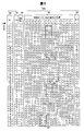
- the storage unit 4 stores the processing table 10A (FIG. 5) input signal IN, and an output signal OUT is obtained.
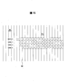
- a processing table 10A as shown in FIG. 5, a processing number column 12, an input signal column 14, a delay signal column 16, a writing position (in-FIFO signal writing position) column 18 and an output signal column 20 are presented.
- 0 to 45 are exemplified as numbers indicating the processing order.
- input signals IN X, A, B,.
- the processing numbers 0 to 45 change with time.
- the input signal IN advances by one clock for each row of each cell in the processing table 10A.
- the input signal IN to the storage unit 4 is input while repeating the same signal twice.
- the same signal indicates “A, A”, “B, B”, “C, C”... For 2 [bits]. Therefore, when the input signal IN is delayed, the input signal IN is extended by one clock, and the value of the delay signal Di is increased by 1 at the 3rd bit (for example, in the case of processing numbers 15 and 18). Further, when the input signal IN advances, the input signal IN is reduced by one clock, and the value of the delay signal Di is reduced by 1 in the next input signal (for example, processing numbers 25, 26, 35, and 40). If).
- the input signal IN on the upper stage side is shifted to the right, and the input signal is positioned at the positions of the “delay signal Di” and the “delay signal Di-1”.
- IN is input.
- the cell portion of the frame encircling portion 22 is indicated by a bold line, indicating the input signal IN, and the position thereof is changed according to the delay signal Di. That is, the input signal IN is input at a different position by the delay signal Di, and the input signal IN is changed.
- the output signal OUT is taken out from the seventh-stage FF 416 of the FIFO configured in the storage unit 4. Therefore, an output signal OUT that is time-controlled according to the delay signal Di is generated as a restoration signal.
- the third embodiment is a configuration example in which the signal restoration circuit described above is installed in a memory controller.
- FIG. 6 will be referred to regarding the third embodiment.
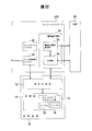
- FIG. 6 is a diagram illustrating a memory controller including a signal restoration circuit and a memory.
- the same parts as those in FIGS. 1 and 4 are denoted by the same reference numerals.
- the signal restoration circuit 2C is an example of a signal restoration circuit according to the present disclosure, and is a signal restoration unit that restores a data signal of a DIMM (Dual Inline Memory Module) 26.
- the signal restoration circuit 2C is installed in the memory controller 24A.
- the memory controller 24 ⁇ / b> A is means for controlling writing and reading of data with respect to the DIMM 26.
- the DIMM 26 is an example of a signal source as well as a data source.
- the signal restoration circuit 2C has a data signal reception function and a signal restoration function, and includes a storage unit 4, a storage control unit 6, and a signal reception unit 28 as shown in FIG.
- the storage unit 4 and the storage control unit 6 are as described in the first embodiment, and the configuration thereof is, for example, as in the second embodiment.
- the signal receiver 28 generates a CK signal from the CLK signal and transmits it to the DIMM 26, and receives a data strobe (DQS) signal and a data (DQ) signal, which are phase reference signals generated from the CK signal by the DIMM 26.
- the DIMM 26 is an example of a memory device.
- the signal receiving unit 28 retimes the DQ signal using the DQS signal, and further switches to the internal clock. Therefore, the signal reception unit 28 includes a clock generation unit 30, a clock output unit 32, a phase setting unit 34, a first phase delay unit 36, a phase detection unit 38, a second phase delay unit 50, A selector 52 and a data holding unit 54 are provided.
- the phase detection unit 38 constitutes delay information detection and generation means
- the clock generation unit 30, the first phase delay unit 36, and the second phase delay unit 50 constitute a delay control unit.
- the clock generation unit 30 divides the CLK signal generated by the LSI internal clock circuit unit (for example, the clock tree unit 306 in FIG. 25) to generate a multi-phase CLK signal.
- a CLK signal of 2 [GHz] is divided by 4 to obtain a CLK signal of 500 [MHz], and a 4-phase CLK signal of 0 degrees, 90 degrees, 180 degrees, and 270 degrees is obtained. Is generated.
- the clock output unit 32 receives a 270 degree CLK signal from the clock generation unit 30, generates a CK signal, and outputs the CK signal to the DIMM 26.
- the DIMM 26 When reading data from the DIMM 26, the DIMM 26 generates a DQS signal from the CK signal received from the signal receiving unit 28, and generates a DQ signal synchronized with the DQS signal.
- the DQS signal and the DQ signal are in phase.
- the phase setting unit 34 is a means for setting a phase shift of a predetermined phase (90 degrees) to the DQS signal and the DQ signal. Therefore, the phase setting unit 34 includes, for example, an input buffer, a delay circuit, an inverter, and the like on the DQS signal side, and includes, for example, an input buffer, a delay circuit, an FF, and the like on the DQ signal side.
- the first phase delay unit 36 is a unit that delays the phase of the DQS signal within a range of, for example, less than 90 degrees as a delay amount with a predetermined phase difference as a unit, and a unit that applies a phase delay to the DQ signal. Therefore, the phase delay unit 36 includes a variable delay circuit, receives the delay signal (DQPHASE), and sets a delay amount of less than 90 degrees, which is a limit value of the delay capability, to the DQS signal.
- DQPHASE delay signal
- the phase detection unit 38 compares the CLK signal generated by the clock generation unit 30 with the DQS signal from the phase delay unit 16 to detect a phase difference, and outputs a DQPHASE signal as information representing this phase difference.
- the DQPHASE signal is an information signal indicating the delay amount of the DQS signal, and is output as delay information from the signal receiving unit 28 and is added to the phase delay unit 36 and the clock generation unit 30.
- the DQPHASE signal is the selection information of the CLK signal.
- the second phase delay unit 50 is means for delaying the phase of the DQS signal in units of 90 degrees as a delay amount in units of a predetermined phase difference, for example. Therefore, the phase delay unit 50 receives the CLK signal from the clock generation unit 30 and obtains a DQ signal whose phase is delayed by a delay amount with a predetermined phase difference as a unit.
- the selector 52 is a means for selecting a plurality of outputs from the phase delay unit 50.
- the selector 52 receives the CLK signal generated by the clock generation unit 30 and uses it as selection information to alternately select the DQ signal and the inverted DQ signal.
- the data holding unit 54 is a holding unit for the DQ signal or the inverted DQ signal selected by the selector 52 and a clock transfer unit. Therefore, the reference CLK signal applied from the LSI internal clock circuit unit is applied to the data holding unit 54 from the input side of the clock generation unit 30.
- the data holding unit 54 holds the DQ signal or the inverted DQ signal in synchronization with the reference CLK signal, switches the clock to the reference CLK signal, and uses the DQ signal or the inverted DQ signal (hereinafter simply referred to as “DQ signal”). Output.
- the DQ signal from the data holding unit 54 is added to the storage control unit 6 and becomes an input signal IN of the storage unit 4. Further, the DQPHASE signal obtained by the phase detection unit 38 is added to the storage control unit 6 as storage control information.
- the reproduction of the received data pulse width from the DQ signal by the signal restoration circuit 2C is as follows.
- the storage unit 4 and the storage control unit 6 constitute a delay control unit for the DQ signal (input signal IN) to realize a process of reproducing the pulse width of the data.
- the storage unit 4 has a FIFO function sufficient to absorb delay variation in data, and increases or decreases the delay time passing through the FIFO configured by the storage unit 4 according to the delay amount of the DQPHASE signal.
- the delay of the reception signal output from the signal reception unit 28, that is, the DQ signal is kept constant, and the data pulse width is reproduced.
- pulse width reproduction is as follows.
- the case where the pulse width of the data becomes narrow is a case where the phase of the received data becomes early. In the storage unit 4 constituting the FIFO, it is necessary to increase the passing delay time. Further, the case where the pulse width of the data becomes wide is a case where the phase of the received data becomes late, and it is necessary to reduce the passing delay time in the storage unit 4 constituting the FIFO.
- the data input method to the FIFO is as described in detail in the first and second embodiments. That is, it is only necessary to simultaneously input the input signal IN to the adjacent 2 [bit] latch means, that is, the FFs (FIGS. 4 and 5), so that the data indefinite (data loss) when the number of FIFO stages is changed. ) Can be eliminated.
- the data pulse width is always constant, the output signal OUT of the signal restoration circuit 2C is generated, and this becomes a stable received signal. That is, the original data signal can be restored faithfully.
- the fourth embodiment is a configuration in which offset information is added to delay information to perform storage control, that is, a configuration in which offset information is added to the first, second, or third embodiment for control.
- FIGS. 7, 8, 9, 10, and 11 for the fourth embodiment.
- 7 is a diagram showing an example of a signal restoration circuit according to the fourth embodiment
- FIG. 8 is a diagram showing a signal restoration circuit as a specific example thereof
- FIGS. 9, 10, and 11 are added with an offset signal. It is a figure which shows the signal restoration process in the case of being performed. 7 and 8, the same parts as those in FIGS. 1, 4 and 6 are denoted by the same reference numerals.
- an adder 56 is installed in the storage control unit 6.
- the adder 56 is an example of a calculation unit that adds the offset signal Offset to the delay signal DQPHASE described above.
- an offset delay signal (DQPHASE + Offset) to which the offset signal Offset is added is added to the selector unit 8 as delay information.
- Other configurations are the same as those of the first embodiment (FIG. 1).
- this signal restoration circuit 2D is configured as shown in FIG. 8, and each output of the adder 56 is a selection input of each selector 801, 802, 803. Moreover, the configuration of the FIFO by the FFs 401, 402, 403,... 416 of the storage unit 4 is the same as that of the second embodiment (FIG. 4).
- the adder 56 outputs the sum of the delay signal DQPHASE and the offset signal Offset. Thereby, the time (number of clocks) required for the input signal DQ to pass through the FIFO can be increased or decreased.
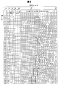
- the process number indicates the transition of time.
- each processing table 10B, 10C, and 10D a processing number column 12, an input signal column 14, a delay signal column 16, a writing position (in-FIFO signal writing position) column 18 and an output signal column 20 are presented. Yes.
- Each processing table 10B, 10C, and 10D is different from the processing table 10A (FIG. 5) in that an offset signal column 58 and a delay signal column 60 with an offset are provided.
- 0 to 45 are exemplified as numbers indicating the processing order.
- the delay signal DQPHASE from the signal receiver 28 (FIG. 6) described above is stored in the delay signal column 16.
- an offset signal Offset is stored as offset information to be added to the delay signal DQPHASE.
- the delayed delay signal column 60 stores an offset delayed signal (DQPHASE + Offset) that is an addition value of the delayed signal DQPHASE in the delayed signal column 16 and the offset signal Offset in the offset signal column 58.
- the input signal DQ on the upper stage side is shifted to the right, the input signal DQ is input to the positions of “delay signal” and “delay signal ⁇ 1”, and the output signal OUT is It is taken out from FF416.
- one clock of the circuit is advanced for each row of cells in FIG. 9, FIG. 10, and FIG.
- the same signal is repeatedly input twice, and when the input signal DQ is delayed, the input signal is extended by one clock, and the value of the delay signal with offset (DQPHASE + Offset) is 3.
- the bit is incremented by 1 (for example, processing numbers 15 and 18).
- the input signal DQ advances, the input signal is reduced by one clock, and the value of the delay signal with offset (DQPHASE + Offset) is reduced by 1 in the next signal (for example, process numbers 25 and 26).
- the DIMM memory controller includes the signal restoration circuit described above and the offset signal setting unit, thereby forming a latency adjustment circuit for the received signal.
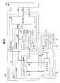
- FIG. 12 is referred to for the fifth embodiment.
- FIG. 12 is a diagram illustrating an example of a latency adjustment circuit according to the fifth embodiment. 12, the same parts as those in FIGS. 6 and 7 are denoted by the same reference numerals.
- the latency adjustment circuit 64 is an example of a signal restoration circuit and a latency adjustment circuit according to the present disclosure, and is a signal restoration unit that restores the data signal of the DIMM 26 and a unit that adjusts the latency of the received data.
- the DIMM 26 is a data source and an example of a signal source.
- the latency adjusting circuit 64 is an example of a means for adjusting the latency of the received signal of the signal receiving unit 28, and as shown in FIG. 12, the storage unit 4 in the signal restoration circuit 2E, An offset setting unit 62A is provided on the memory controller 24B side.
- the signal restoration circuit 2E constitutes an interface unit of the memory controller 24B. Since the storage unit 4, the storage control unit 6, the signal receiving unit 28, and the memory controller 24B are as described above, description thereof is omitted.
- the offset setting unit 62A is an example of a unit that generates the above-described offset signal Offset to be set in the storage control unit 6 and sets an offset using the offset signal.
- the offset setting unit 62A includes a control register 66, a data storage register 68, and an arithmetic unit 70.
- the control register 66 is an example of a means for setting data write timing and data fetch timing in the DIMM 26, and is provided in the memory controller 24B and controlled by the arithmetic unit 70.
- the data storage register 68 is an example of various data storage means for latency control, and is provided in the memory controller 24B and also serves as means for holding offset data. That is, the data storage register 68 also serves as a FIFO setting register, receives a DQ signal from the storage unit 4, outputs an offset signal Offset, and adds the offset signal Offset to the adder 56 of the storage control unit 6.
- the computing device 70 is an example of a delay information detecting unit.
- the computing device 70 is an example of a processor installed outside the memory controller 24B, and includes an arithmetic processing unit 72 and a storage unit 74.
- the arithmetic processing unit 72 is an example of a unit that executes a firmware program stored in the storage unit 74.
- the storage unit 74 is a firmware program storage unit and constitutes a data storage unit.
- the storage unit 74 stores a firmware program unit 75, a data table 76 (FIG. 19), and a data table 78 (FIG. 20).
- the storage unit 74 is installed inside the arithmetic device 70, but may be installed outside the arithmetic device 70.
- FIG. 13 is a diagram illustrating a circuit including a DIMM and a memory controller.
- the DIMM 26 of this embodiment includes DRAM (0), DRAM (1), DRAM (2)... DRAM (8) and a register R as an example of a plurality of memory devices.
- the memory controller 24B includes a plurality of signal receiving units 280, 281, 282,.
- Each of the signal receiving units 280, 281, 282,... 288 plays the role of the FIFO described above, and therefore, for the DQS group, DRAM (0), DRAM (1), DRAM (2). ), The delay of the received signal of the memory controller 24B obtained through each signal restoration circuit 2E is kept constant, and the data pulse width can be restored.
- each of the signal receiving units 280, 281, 282,... 288 is performed individually for each of the DRAM (0) to the DRAM (8), resulting in variations depending on the circuit configuration of the interface. In order to make them uniform, latency control is necessary. Therefore, in the memory controller 24B of this embodiment, the signal reception units 280 to 288 eliminate the data shift in units of clock cycles between the DQS groups.
- the FIFO has an offset setting unit 62A as an interface for transmitting offset information from the memory controller 24B, and the storage control unit 6 realizes the delay information with offset in the storage unit 4 constituting the FIFO. That is, an offset can be added to the delay signal from the memory controller 24B side.
- predetermined continuous data is written to a predetermined continuous address of the DIMM 26 according to an instruction from the arithmetic unit 70 (FIG. 12). Read data continuously from each continuous address.
- the arithmetic unit 70 determines an offset value from the data content read continuously, and adds this offset value to the delay signal.
- the latency at the time of reading that is, the time (delay time) from the issue of the read command to the reception of the read data is known.
- This delay time can be adjusted to a predetermined latency. Further, if the variation range of the latency can be limited, it is possible to omit the unnecessary latency consumed in the storage unit 4 constituting the FIFO.
- the memory controller 24B determines an offset value set in the data storage register 68 of the FIFO (FIG. 14).
- FIG. 14 is a flowchart illustrating an example of a processing procedure for latency adjustment.
- This latency adjustment processing procedure is an example of the latency adjustment method of the present disclosure, is configured by a program executed by a computer, and includes a latency detection function and a latency adjustment function based on latency detection.
- the memory controller 24B writes data to the DIMM 26 in accordance with an instruction from the arithmetic unit 70 that executes the firmware (step S21).
- the data to be written is data in which values from 0 to f (FIG. 15) are continuous.
- the arithmetic unit 70 designates the data fetch timing (Get timing in FIGS. 15 and 16) to the control register 66 (step S22). In the second data capture when the frequencies are different, the Get timing (Get timing in FIGS. 17 and 18) is delayed by one cycle of the clock from the first data capture.
- the arithmetic unit 70 writes “0” in the data storage register 68 (step S23).
- the data storage register 68 also serves as a FIFO setting register including the storage unit 4.
- the computing device 70 issues a read instruction, and the memory controller 24B fetches a value into the data storage register 68 at the timing designated by the computing device 70 in step S22 (step S24).
- the arithmetic unit 70 reads data from the data storage register 68 (step S25).
- the arithmetic unit 70 determines the FIFO value from the value read from the data storage register 68 with reference to the data tables 76 (FIG. 19) and 78 (FIG. 20) of the storage unit 74, and the data storage register A FIFO offset value (delay value) is set to 68 (step S26). This process is performed by the second data capture when the frequency is different. The following will be done:
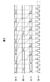
- FIGS. 15, 16, 17, and 18 for the latency adjustment.
- 15 and 17 are diagrams showing data before latency adjustment
- FIGS. 16 and 18 are diagrams showing data after latency adjustment.
- a vertical line 80 is an edge of the system clock.
- the above-described flowchart (FIG. 14) is executed only once. If the relationship between the system clock and the data frequency of the DIMM 26 is 1: 2, as shown in FIG. 17, the above-described flowchart (FIG. 14) is executed twice. Further, if the relationship between the frequency of the system clock and the frequency of the DIMM 26 is 1: N, the latency can be made uniform by executing the above-described flowchart (FIG. 14) N times (FIGS. 16 and 18).
- the read data of the DRAM (0), DRAM (1), DRAM (2), and DRAM (3) is as shown in FIG. , Continuously taken out.
- the read data of the above-described DRAM (0), DRAM (1), DRAM (2), and DRAM (3) is subjected to latency adjustment. Then, as shown in FIG. 18, the data are collected continuously, but the data is ready. In this case, the acquisition timing is each position of Get1 and Get2.
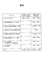
- 19 and 20 are referred to for the data tables 76 and 78 described above.
- 19 and 20 are diagrams illustrating an example of the data table.
- a read value 82 is set and a set value 84 corresponding to the read value 82 is set.
- the read value 82 is a data value read from the DRAM (0), DRAM (1), DRAM (2),.
- the set value 84 is, for example, a read value fetch (Get) timing for each DRAM (0), DRAM (1), DRAM (2)...
- Get read value fetch
- the data value is adjusted to a predetermined value “5”. Is the value to set.
- “9” is obtained at the Get timing, as shown in FIG. Therefore, “4” of the set value 84 is selected from “9” of the read value 82 of the data table 76 (FIG. 19).
- the Get timing of the DRAM (0) is shifted by 4 clocks. This process is an example, and if the reference lead value is different, another set value is used.
- the read value 82 is stored in the storage unit 74 by the firmware program, and a setting value 84 corresponding to the read value 82 is stored.
- the system clock and the clock of the DIMM 26 are the same.
- a set value 90 corresponding to the first read value 86 and the second read value 88 is set.
- the arithmetic unit 70 changes the value specified in the control register 66, that is, the above-described Get timing (FIGS. 15 and 16), the data alignment timing can be changed.
- the Get timing can be aligned with the data value “5” as shown in FIG.
- the timing of Get1 is the latter half of the data value “2” as shown in FIG.
- this error information is sent to the memory controller 24B.
- the memory controller 24B rereads data (read retry) according to the error information. This increases the accuracy of the offset value.
- a reception circuit that receives received data and a reference signal (DQS) as a signal restoration circuit and outputs a relative delay amount (DQPHASE) with respect to an internal reference clock and fetched data is configured.
- DQS reference signal
- DQPHASE relative delay amount
- the relative delay amount (DQPHASE) with respect to the internal reference clock can be handled as a digital amount.
- the latency adjustment can be configured with FIFO.
- DIMMs with a data transfer rate exceeding 1 [Gbps] delay variations related to data transmission may exceed the data width.
- the DIMM adopts a Fly-by topology in which the wiring from the internal register to each DRAM is not equal in length, the delay time does not match between the DQS groups, and the variation of the clock delay becomes 1000 [ps].
- the signal receiver 28 may be configured. If this signal receiving unit 28 is used, such variation can be absorbed and a stable data reading operation can be performed.
- the signal receiving unit 28 is used.
- the output stage of the signal receiving unit 28 has a signal for controlling the number of FIFO stages, and the data shift is aligned within the interface of the memory controller 24B.
- the memory controller 24B Since the memory controller 24B has a signal indicating that an error has occurred in the signal receiving unit 28, it has a function of retrying a read when an error occurs, so that the reliability of latency adjustment is improved.
- a data transmission device using the signal receiving unit 28 can be configured.
- the interface of the memory controller 24B has a signal (offset value) for controlling the number of FIFO stages.
- a signal for transmitting error information of the signal receiving unit 28 may be provided in the interface unit of the memory controller 24B.
- the memory controller 24B may refer to a register storing DIMM access information and request a read retry.
- the signal restoration circuit and the memory controller are separately configured.
- FIG. 21 is referred to for the sixth embodiment.
- FIG. 21 is a circuit diagram showing a memory controller, an arithmetic unit, a signal restoration circuit, and a DIMM.
- the signal restoration circuit 2E and the memory controller 24C are separately configured, and the memory controller 24C includes the offset setting unit 62A described above.
- the memory controller 24C includes the offset setting unit 62A described above.
- Such a configuration also provides the same functions and effects as those of the fifth embodiment.
- FIG. 21 the same parts as those in FIG.
- the memory controller includes a delay amount measuring unit for the latency adjustment described above.
- FIG. 22 is referred to for the seventh embodiment.
- FIG. 22 is a circuit diagram showing an example of a latency adjustment circuit according to the seventh embodiment. 22, the same parts as those in FIG. 12 are denoted by the same reference numerals.
- a memory controller 24D is provided together with the DIMM 26, and an arithmetic unit 70 is provided in the memory controller 24D.
- the memory controller 24D of this embodiment is provided with a delay amount measuring unit 94 as well as the control register 66 and the data storage register 68 described above.
- the delay amount measuring unit 94 is an example of a means for measuring an offset delay amount, transmits a delay measurement signal to the DIMM 26, compares the delay amount measurement signal with a received signal from the DIMM 26, and determines a delay measurement signal. Is a means for measuring a delay time from the transmission time to the reception time of the received signal. This delay time is a delay amount, and this delay amount is an offset delay amount, which is also the above-described offset signal Offset.
- the delay amount measurement unit 94 includes a delay measurement signal generation unit 96 and a comparison unit 98.
- the delay measurement signal generation unit 96 is an example of the delay measurement signal generation unit described above, and transmits the delay measurement signal to the DIMM 26 and transfers it to the comparison unit 98.
- the comparison unit 98 is an example of a unit that measures a delay time from the transmission time of the delay measurement signal to the reception time of the reception signal.
- the comparison unit 98 compares the delay measurement signal with the reception signal from the DIMM 26 and transmits the transmission time of the delay measurement signal. The time from when the received signal is received to the time of reception is measured as the delay time. This delay time is taken into the arithmetic unit 70 and stored in the data storage register 68 as delay information.
- the arithmetic unit 70 executes the firmware program in the firmware program unit 75 of the storage unit 74 and causes the delay amount measurement unit 94 to measure the delay amount.
- An offset signal may be generated with such a configuration, and an offset value may be added to the adder 56 (FIG. 7) described above to generate a delay signal with an offset, and adjust the latency of the received signal.
- the delay amount measuring unit 94 is installed in the memory controller 24D, but it may be installed in the signal restoration circuit 2A (or 2B to 2E), and the above-described latency adjustment can be performed.
- the storage unit 74 may be installed outside the arithmetic device 70.
- a step (or function) for controlling the time is Storing the input signals in the order of input, receiving the delay information of the input signals, and reading out the input signals from the storage unit capable of reading the input signals in the order of the input arrangement in accordance with the delay information (or function);
- delay information is constant, the input signals are stored in the order of input.
- the delay information transitions, a position in the array is selected according to the transition, and the input signal is stored at the position. Steps (or functions).
- the processing procedure of the signal restoration process may further include a step (or function) of comparing the input signal with a reference clock signal and detecting delay information of the received signal with respect to the reference clock signal.
- a step (or function) of measuring the offset delay amount of the received signal with respect to the transmitted delay measurement signal, the offset delay amount, and the delay amount detection unit A step (or function) of generating the delay information from the delay amount and changing the position of the storage array in accordance with the delay information.
- the signal restoration circuit 2E (FIG. 12) installed in the memory controller 24 or the signal restoration circuit 2E (FIG. 21) installed outside the memory controller 24 is exemplified as the signal restoration circuit.
- the signal restoration circuit of the present disclosure is not limited to the above embodiment.
- the signal restoration circuit of the present disclosure is used for signal restoration by using it other than the memory interface circuit such as the memory controller 24.
- the memory controller 24 has been described, but the memory controller of the present disclosure is not limited to the above embodiment.
- the processor 100 may be configured using the memory controller of the present disclosure, or the computer 200 (FIG. 24) may be configured.
- the processor 100 is composed of, for example, a CPU (Central Processing Unit) or an MPU (Micro Processor Unit). As shown in FIG. 23, the processor 100 is provided with a memory controller 24 for controlling data transfer of the DIMM 26, and an arithmetic processing unit 70 as means for executing the firmware program unit 75 and means for executing arithmetic processing and the like. May be.
- the memory controller 24 may include a signal restoration circuit 2A (or 2B to 2E). Also with such a configuration, the effects in the above embodiment can be obtained, and signal (data) restoration, data transfer speedup, and reliability can be improved.
- the computer 200 may include a memory controller 24 inside a chip set 204 installed between the CPU 202 and the DIMM 26.
- the memory controller 24 may include a signal restoration circuit 2A (or 2B to 2E). Also with such a configuration, the effects in the above embodiment can be obtained, and signal (data) restoration, data transfer speedup, and reliability can be improved.
- the memory controller 24 may be provided inside the CPU 202, and the signal restoration circuit 2A (or 2B to 2E) described above may be configured inside the memory controller 24. Also with such a configuration, the effects in the above embodiment can be obtained, and signal (data) restoration, data transfer speedup, and reliability can be improved.
- the frequency may be set to 2 [GHz] for the reference internal clock signal, but the present invention is not limited to this.
- the frequency of the clock signal to be set is arbitrary, and the numerical values described in the above embodiment are merely examples.
- the signal restoration circuit, the latency adjustment circuit, and the like are exemplified, but the present invention is not limited to these.
- the latency from each memory device can be aligned with the same latency based on the clocks of various devices, and a device using a plurality of memory devices Available for processing.
- the comparative example is a signal receiving circuit for a signal with phase fluctuation, and is an example of a signal receiving unit of a memory controller.
- FIG. 25 is a diagram showing a comparative example of the memory controller
- FIG. 26 is a diagram showing an example of trial calculation of delay variation of the circuit
- FIG. 27 is a diagram showing a clock wiring form on the DIMM
- FIG. 28 is another diagram on the DIMM. It is a figure which shows the clock wiring form.
- the simplest way to receive a DDR signal from a DIMM is to configure a memory controller 300 as shown in FIG.
- a signal receiving unit 304 is installed as a means for receiving a signal from the DIMM 302
- a clock tree unit 306 is installed as a means for giving a clock signal to the signal receiving unit 304.
- the clock tree unit 306 and the signal receiving unit 304 are configured by LSI. To do.
- the signal receiving unit 304 receives a signal whose phase of input data fluctuates and constitutes a signal receiving circuit of the DDR memory interface circuit.
- the signal receiving unit 304 includes FF circuits 308, 310, 312, 314, 316, DL 318 and 320, an output buffer 322, and input buffers 324 and 326.
- the clock tree unit 306 constitutes an LSI internal clock circuit unit, and includes inverters 328, 330, 332, 334, 336, 338, and 340.
- the DIMM 302 is provided with an input buffer 342 and an output buffer 344.
- the signal receiving unit 304 receives the CLK signal generated by the clock tree unit 306, generates the CK signal CK 0, and transmits it to the DIMM 302.
- the DIMM 302 generates a DQS signal from the CK signal, and sends it back to the signal receiving unit 304 together with the DQ signal.
- the DQS signal is retimed using the DQS signal, and is further switched to the internal clock. At this time, the timing relationship between the internal clock and the received data is required to be within a certain range in order to reliably receive the data at the reception point latch.
- the signal reception point is assumed to be the input unit of the FF 310 on the output side of the DL 318 (FIG. 25).
- the transmission line length is 0 [mm]
- the received data is delayed from 982 [ps] to 4,156 [ps] when viewed from the clock reference of the reception point latch in the LSI constituting the signal receiving unit 304.
- the JEDEC Joint Electron Devices Engineering Council defines the dispersion absorbing means as Write Leveling. However, there is no provision regarding timing mismatch at the time of signal reception.
- the signal restoration circuit, the memory controller, the processor, the computer, or the signal restoration method of the present disclosure proposes a mechanism for matching the data timing by absorbing the above-described delay variation of the DDR3 interface and adjusting the data latency between the DRAMs. Yes.
- the above-described problems are solved.
- the signal restoration circuit, latency adjustment circuit, memory controller, processor, computer, signal restoration method, and latency adjustment method of the present disclosure are not limited to the above description. It goes without saying that various modifications and changes can be made by those skilled in the art based on the gist disclosed in the claims or disclosed in the embodiments for carrying out the invention. It goes without saying that such modifications and changes are included in the scope of the present invention.
- the signal restoration circuit, the latency adjustment circuit, the memory controller, the processor, the computer, the signal restoration method, and the latency adjustment method of the present disclosure are related to signal reception, can suppress delay variation on the circuit, and can align the latency of received data. It provides a highly practical memory controller and is useful.
Landscapes
- Engineering & Computer Science (AREA)
- Microelectronics & Electronic Packaging (AREA)
- Computer Hardware Design (AREA)
- Physics & Mathematics (AREA)
- Nonlinear Science (AREA)
- Dram (AREA)
- Networks Using Active Elements (AREA)
- Information Transfer Systems (AREA)
Abstract
Description
4 記憶部
6 記憶制御部
28 信号受信部
64 レイテンシ調整回路
70 演算装置
Claims (16)
- 入力信号を入力順に配列させて記憶し、配列順に前記入力信号の読み出しが可能な記憶部と、
前記入力信号の遅延情報により、前記記憶部における前記入力信号の入力から出力までの遅延時間を制御する記憶制御部と、
を備えることを特徴とする信号復元回路。 - 前記記憶制御部は、前記入力信号の遅延量が大きい場合には、前記遅延時間を減少させ、前記入力信号の遅延量が小さい場合には、前記遅延時間を増加させることを特徴とする、請求項1に記載の信号復元回路。
- 前記記憶制御部は、前記入力信号の遅延情報を受け、前記記憶部から前記遅延情報に従って前記入力信号を配列順に読み出すとともに、該遅延情報が一定の場合には前記入力信号を前記入力順に記憶させ、前記遅延情報が遷移した場合にはその遷移に応じて前記配列中の位置を選択し、該位置に前記入力信号を記憶させることを特徴とする、請求項1に記載の信号復元回路。
- 更に、前記入力信号と基準クロック信号とを比較し、前記基準クロック信号に対する前記入力信号の前記遅延情報を出力する遅延情報検出部と、
を備えたことを特徴とする請求項1に記載の信号復元回路。 - 前記入力信号は、メモリから受信したデータ信号であることを特徴とする請求項1に記載の信号復元回路。
- 前記記憶部は、先入れ先出し(FIFO)が可能な回路であって、該回路が2以上のフリップフロップで構成し、隣り合う2つのフリップフロップに同一データを入力することを特徴とする、請求項1に記載の信号復元回路。
- 更に、送信した遅延計測信号に対する受信信号のオフセット遅延量を計測するオフセット遅延量計測部と、
を備え、前記記憶制御部は、前記オフセット遅延量と、前記遅延情報検出部で得た前記遅延量とを含む前記遅延情報を生成することを特徴とする、請求項4に記載の信号復元回路。 - 請求項1ないし請求項7の何れかの請求項に記載の信号復元回路をメモリデバイス毎に備え、各メモリデバイスリードデータのレイテンシを前記信号復元回路を用いてレイテンシを調整することを特徴とするレイテンシ調整回路。
- 請求項1ないし請求項7のいずれかの請求項に記載の信号復元回路又は請求項8に記載のレイテンシ調整回路を備えることを特徴とするメモリコントローラ。
- 請求項1ないし請求項7のいずれかの請求項に記載の信号復元回路、請求項8に記載のレイテンシ調整回路又は請求項9に記載のメモリコントローラを備えることを特徴とするプロセッサ。
- 請求項1ないし請求項7のいずれかの請求項に記載の信号復元回路、請求項8に記載のレイテンシ調整回路、請求項9に記載のメモリコントローラ又は請求項10に記載のプロセッサを備えることを特徴とするコンピュータ。
- 入力信号を入力順に配列させて記憶し、配列順に前記入力信号の読み出しが可能な記憶部に、前記入力信号を前記入力順に記憶するステップと、
前記入力信号の遅延情報により、前記記憶部における前記入力信号の入力から出力までの遅延時間を制御するステップと、
を含むことを特徴とする信号復元方法。 - 前記入力信号の前記遅延情報を受け、前記記憶部から前記入力信号を前記遅延情報に従って配列順に読み出すステップと、
前記遅延情報が一定の場合には前記入力信号を前記入力順に記憶させ、前記遅延情報が遷移した場合にはその遷移に応じて前記配列中の位置を選択し、該位置に前記入力信号を記憶させるステップと、
を含むことを特徴とする、請求項12に記載の信号復元方法。 - 更に、入力信号と基準クロック信号とを比較し、前記基準クロック信号に対する前記入力信号の遅延情報を検出するステップと、
を含むことを特徴とする、請求項12に記載の信号復元方法。 - 更に、送信した遅延計測信号に対する受信信号のオフセット遅延量を計測するステップと、
前記オフセット遅延量と、遅延量検出部で検出された遅延量とから前記遅延情報を生成し、該遅延情報に応じて記憶配列の位置を変更するステップと、
を含むことを特徴とする、請求項13に記載の信号復元方法。 - 請求項12ないし請求項15のいずれかの請求項に記載の信号復元方法を含み、各メモリデバイスリードデータのレイテンシを調整することを特徴とするレイテンシ調整方法。
Priority Applications (6)
| Application Number | Priority Date | Filing Date | Title |
|---|---|---|---|
| KR1020127013046A KR20120085824A (ko) | 2009-12-25 | 2009-12-25 | 신호 복원 회로, 레이턴시 조정 회로, 메모리 컨트롤러, 프로세서, 컴퓨터, 신호 복원 방법, 및 레이턴시 조정 방법 |
| EP09852589A EP2518630A4 (en) | 2009-12-25 | 2009-12-25 | SIGNAL DECODER SWITCHING, LATCH SETUP SWITCH, MEMORY CONTROL, PROCESSOR, COMPUTER, SIGNAL DECODING METHOD, AND LATENCE SETTING METHOD |
| CN2009801625337A CN102667731A (zh) | 2009-12-25 | 2009-12-25 | 信号复原电路、等待时间调整电路、存储器控制器、处理器、计算机、信号复原方法以及等待时间调整方法 |
| JP2011547183A JP5331902B2 (ja) | 2009-12-25 | 2009-12-25 | 信号復元回路、レイテンシ調整回路、メモリコントローラ、プロセッサ、コンピュータ、信号復元方法及びレイテンシ調整方法 |
| PCT/JP2009/071686 WO2011077574A1 (ja) | 2009-12-25 | 2009-12-25 | 信号復元回路、レイテンシ調整回路、メモリコントローラ、プロセッサ、コンピュータ、信号復元方法及びレイテンシ調整方法 |
| US13/472,575 US8788780B2 (en) | 2009-12-25 | 2012-05-16 | Signal restoration circuit, latency adjustment circuit, memory controller, processor, computer, signal restoration method, and latency adjustment method |
Applications Claiming Priority (1)
| Application Number | Priority Date | Filing Date | Title |
|---|---|---|---|
| PCT/JP2009/071686 WO2011077574A1 (ja) | 2009-12-25 | 2009-12-25 | 信号復元回路、レイテンシ調整回路、メモリコントローラ、プロセッサ、コンピュータ、信号復元方法及びレイテンシ調整方法 |
Related Child Applications (1)
| Application Number | Title | Priority Date | Filing Date |
|---|---|---|---|
| US13/472,575 Continuation US8788780B2 (en) | 2009-12-25 | 2012-05-16 | Signal restoration circuit, latency adjustment circuit, memory controller, processor, computer, signal restoration method, and latency adjustment method |
Publications (1)
| Publication Number | Publication Date |
|---|---|
| WO2011077574A1 true WO2011077574A1 (ja) | 2011-06-30 |
Family
ID=44195134
Family Applications (1)
| Application Number | Title | Priority Date | Filing Date |
|---|---|---|---|
| PCT/JP2009/071686 Ceased WO2011077574A1 (ja) | 2009-12-25 | 2009-12-25 | 信号復元回路、レイテンシ調整回路、メモリコントローラ、プロセッサ、コンピュータ、信号復元方法及びレイテンシ調整方法 |
Country Status (6)
| Country | Link |
|---|---|
| US (1) | US8788780B2 (ja) |
| EP (1) | EP2518630A4 (ja) |
| JP (1) | JP5331902B2 (ja) |
| KR (1) | KR20120085824A (ja) |
| CN (1) | CN102667731A (ja) |
| WO (1) | WO2011077574A1 (ja) |
Cited By (4)
| Publication number | Priority date | Publication date | Assignee | Title |
|---|---|---|---|---|
| WO2013035223A1 (ja) * | 2011-09-06 | 2013-03-14 | エヌイーシーコンピュータテクノ株式会社 | メモリコントローラ及びメモリ制御方法 |
| WO2013042233A1 (ja) * | 2011-09-21 | 2013-03-28 | 富士通株式会社 | 半導体装置 |
| JP2015138485A (ja) * | 2014-01-24 | 2015-07-30 | 富士通株式会社 | メモリコントローラ及び情報処理装置 |
| US9300559B2 (en) | 2013-08-14 | 2016-03-29 | Hyundai Motor Company | Message processing method of gateway |
Families Citing this family (5)
| Publication number | Priority date | Publication date | Assignee | Title |
|---|---|---|---|---|
| US8971471B2 (en) * | 2011-12-07 | 2015-03-03 | Imagine Communications Corp. | Predictable coding delay over communications networks |
| WO2015065426A1 (en) | 2013-10-31 | 2015-05-07 | Hewlett-Packard Development Company, L.P. | Memory access for busy memory |
| CN106897234B (zh) * | 2016-09-23 | 2019-07-30 | 常州新智源电子科技有限公司 | 一种处理器以及处理器内置存储器的控制方法 |
| US10592442B2 (en) * | 2017-12-11 | 2020-03-17 | Advanced Micro Devices, Inc. | Asynchronous buffer with pointer offsets |
| CN108665922B (zh) * | 2018-04-24 | 2021-09-24 | 电子科技大学 | 一种应用于雷达模拟的可变双向数字延迟方法 |
Citations (12)
| Publication number | Priority date | Publication date | Assignee | Title |
|---|---|---|---|---|
| JPH05258589A (ja) * | 1992-03-10 | 1993-10-08 | Fujitsu General Ltd | 可変長シフトレジスタ |
| JPH07169058A (ja) | 1993-12-10 | 1995-07-04 | Canon Inc | 光学的情報再生装置 |
| JPH10190639A (ja) * | 1996-12-20 | 1998-07-21 | Matsushita Electric Ind Co Ltd | クロック乗せ替え回路 |
| JPH1125029A (ja) | 1997-07-04 | 1999-01-29 | Fujitsu Ltd | メモリサブシステム |
| JPH11167515A (ja) | 1997-10-03 | 1999-06-22 | Matsushita Electric Ind Co Ltd | データ伝送装置及びデータ伝送方法 |
| JP2003050739A (ja) | 2001-08-06 | 2003-02-21 | Matsushita Electric Ind Co Ltd | メモリ制御装置 |
| JP2003099321A (ja) | 2001-09-21 | 2003-04-04 | Ricoh Co Ltd | メモリ制御装置 |
| JP2006107352A (ja) | 2004-10-08 | 2006-04-20 | Fujitsu Ltd | メモリコントローラ |
| JP2007164697A (ja) | 2005-12-16 | 2007-06-28 | Shinko Electric Ind Co Ltd | 半導体集積回路およびメモリシステム並びにクロック信号設定方法 |
| JP2007536773A (ja) | 2004-04-29 | 2007-12-13 | コーニンクレッカ フィリップス エレクトロニクス エヌ ヴィ | 多重データレートramメモリコントローラ |
| JP2008071018A (ja) | 2006-09-13 | 2008-03-27 | Matsushita Electric Ind Co Ltd | メモリインターフェース回路 |
| JP2009076991A (ja) * | 2007-09-18 | 2009-04-09 | Fujitsu Ltd | 可変遅延回路,遅延時間制御方法および単位回路 |
Family Cites Families (7)
| Publication number | Priority date | Publication date | Assignee | Title |
|---|---|---|---|---|
| US5084839A (en) * | 1990-02-05 | 1992-01-28 | Harris Corporation | Variable length shift register |
| US6243797B1 (en) | 1997-02-18 | 2001-06-05 | Micron Technlogy, Inc. | Multiplexed semiconductor data transfer arrangement with timing signal generator |
| JP3758285B2 (ja) * | 1997-03-17 | 2006-03-22 | ソニー株式会社 | 遅延回路およびそれを用いた発振回路 |
| US6356485B1 (en) * | 1999-02-13 | 2002-03-12 | Integrated Device Technology, Inc. | Merging write cycles by comparing at least a portion of the respective write cycle addresses |
| DE10345236B3 (de) * | 2003-09-29 | 2005-03-10 | Infineon Technologies Ag | Verzögerungsregelkreis |
| US7298188B2 (en) | 2004-04-30 | 2007-11-20 | Fujitsu Limited | Timing adjustment circuit and memory controller |
| US7847595B2 (en) * | 2006-01-26 | 2010-12-07 | Nec Corporation | Input circuit and semiconductor integrated circuit comprising the input circuit |
-
2009
- 2009-12-25 JP JP2011547183A patent/JP5331902B2/ja active Active
- 2009-12-25 WO PCT/JP2009/071686 patent/WO2011077574A1/ja not_active Ceased
- 2009-12-25 KR KR1020127013046A patent/KR20120085824A/ko not_active Ceased
- 2009-12-25 CN CN2009801625337A patent/CN102667731A/zh active Pending
- 2009-12-25 EP EP09852589A patent/EP2518630A4/en not_active Withdrawn
-
2012
- 2012-05-16 US US13/472,575 patent/US8788780B2/en active Active
Patent Citations (12)
| Publication number | Priority date | Publication date | Assignee | Title |
|---|---|---|---|---|
| JPH05258589A (ja) * | 1992-03-10 | 1993-10-08 | Fujitsu General Ltd | 可変長シフトレジスタ |
| JPH07169058A (ja) | 1993-12-10 | 1995-07-04 | Canon Inc | 光学的情報再生装置 |
| JPH10190639A (ja) * | 1996-12-20 | 1998-07-21 | Matsushita Electric Ind Co Ltd | クロック乗せ替え回路 |
| JPH1125029A (ja) | 1997-07-04 | 1999-01-29 | Fujitsu Ltd | メモリサブシステム |
| JPH11167515A (ja) | 1997-10-03 | 1999-06-22 | Matsushita Electric Ind Co Ltd | データ伝送装置及びデータ伝送方法 |
| JP2003050739A (ja) | 2001-08-06 | 2003-02-21 | Matsushita Electric Ind Co Ltd | メモリ制御装置 |
| JP2003099321A (ja) | 2001-09-21 | 2003-04-04 | Ricoh Co Ltd | メモリ制御装置 |
| JP2007536773A (ja) | 2004-04-29 | 2007-12-13 | コーニンクレッカ フィリップス エレクトロニクス エヌ ヴィ | 多重データレートramメモリコントローラ |
| JP2006107352A (ja) | 2004-10-08 | 2006-04-20 | Fujitsu Ltd | メモリコントローラ |
| JP2007164697A (ja) | 2005-12-16 | 2007-06-28 | Shinko Electric Ind Co Ltd | 半導体集積回路およびメモリシステム並びにクロック信号設定方法 |
| JP2008071018A (ja) | 2006-09-13 | 2008-03-27 | Matsushita Electric Ind Co Ltd | メモリインターフェース回路 |
| JP2009076991A (ja) * | 2007-09-18 | 2009-04-09 | Fujitsu Ltd | 可変遅延回路,遅延時間制御方法および単位回路 |
Non-Patent Citations (1)
| Title |
|---|
| See also references of EP2518630A4 * |
Cited By (8)
| Publication number | Priority date | Publication date | Assignee | Title |
|---|---|---|---|---|
| WO2013035223A1 (ja) * | 2011-09-06 | 2013-03-14 | エヌイーシーコンピュータテクノ株式会社 | メモリコントローラ及びメモリ制御方法 |
| JP2013054692A (ja) * | 2011-09-06 | 2013-03-21 | Nec Computertechno Ltd | メモリコントローラ及びメモリ制御方法 |
| US9305617B2 (en) | 2011-09-06 | 2016-04-05 | Nec Platforms, Ltd. | Data and strobe decompressing memory controller and memory control method |
| WO2013042233A1 (ja) * | 2011-09-21 | 2013-03-28 | 富士通株式会社 | 半導体装置 |
| JP5673842B2 (ja) * | 2011-09-21 | 2015-02-18 | 富士通株式会社 | 半導体装置 |
| US8976619B2 (en) | 2011-09-21 | 2015-03-10 | Fujitsu Limited | Semiconductor apparatus |
| US9300559B2 (en) | 2013-08-14 | 2016-03-29 | Hyundai Motor Company | Message processing method of gateway |
| JP2015138485A (ja) * | 2014-01-24 | 2015-07-30 | 富士通株式会社 | メモリコントローラ及び情報処理装置 |
Also Published As
| Publication number | Publication date |
|---|---|
| CN102667731A (zh) | 2012-09-12 |
| EP2518630A1 (en) | 2012-10-31 |
| US20120226884A1 (en) | 2012-09-06 |
| JP5331902B2 (ja) | 2013-10-30 |
| KR20120085824A (ko) | 2012-08-01 |
| EP2518630A4 (en) | 2013-01-23 |
| JPWO2011077574A1 (ja) | 2013-05-02 |
| US8788780B2 (en) | 2014-07-22 |
Similar Documents
| Publication | Publication Date | Title |
|---|---|---|
| JP5331902B2 (ja) | 信号復元回路、レイテンシ調整回路、メモリコントローラ、プロセッサ、コンピュータ、信号復元方法及びレイテンシ調整方法 | |
| JP5537568B2 (ja) | 信号受信回路、メモリコントローラ、プロセッサ、コンピュータ及び位相制御方法 | |
| US7590008B1 (en) | PVT compensated auto-calibration scheme for DDR3 | |
| CN102047340B (zh) | 用于多相时钟产生的设备和方法 | |
| JP4878215B2 (ja) | インタフェース回路及びメモリ制御装置 | |
| US7672191B2 (en) | Data output control circuit | |
| CN101149961B (zh) | 用于控制存储器接口的设备和方法 | |
| US7499370B2 (en) | Synchronous semiconductor memory device | |
| JP5653177B2 (ja) | メモリインターフェース回路及び半導体装置 | |
| US8209560B2 (en) | Transmission system where a first device generates information for controlling transmission and latch timing for a second device | |
| JP2008052335A (ja) | インターフェース回路 | |
| US8976619B2 (en) | Semiconductor apparatus | |
| US20240290365A1 (en) | Circuit for aligning command input data and semiconducter device including the same | |
| CN100412749C (zh) | 存储器信号定时调校方法与相关装置 | |
| JP2012027734A (ja) | メモリコントローラおよびメモリアクセスシステム | |
| JP5113433B2 (ja) | メモリコントローラ | |
| US20250298515A1 (en) | Low-overhead periodic adjustment for memory timing | |
| JP5005928B2 (ja) | インタフェース回路及びそのインタフェース回路を備えた記憶制御装置 | |
| JP2010079520A (ja) | メモリモジュールのコントローラ及びメモリモジュールのコントローラの制御方法 | |
| JP2006065470A (ja) | メモリ制御方法および装置 | |
| JP4855908B2 (ja) | レイテンシーカウンター及び関連方法 | |
| JP4819493B2 (ja) | 回路システム | |
| CN116569263A (zh) | 集成电路存储器设备中的信号偏斜校正 | |
| JP2005094597A (ja) | 遅延制御装置 |
Legal Events
| Date | Code | Title | Description |
|---|---|---|---|
| WWE | Wipo information: entry into national phase |
Ref document number: 200980162533.7 Country of ref document: CN |
|
| 121 | Ep: the epo has been informed by wipo that ep was designated in this application |
Ref document number: 09852589 Country of ref document: EP Kind code of ref document: A1 |
|
| WWE | Wipo information: entry into national phase |
Ref document number: 2011547183 Country of ref document: JP |
|
| ENP | Entry into the national phase |
Ref document number: 20127013046 Country of ref document: KR Kind code of ref document: A |
|
| WWE | Wipo information: entry into national phase |
Ref document number: 2009852589 Country of ref document: EP |
|
| NENP | Non-entry into the national phase |
Ref country code: DE |