WO2011077794A1 - Dispositif de retenue de papier - Google Patents
Dispositif de retenue de papier Download PDFInfo
- Publication number
- WO2011077794A1 WO2011077794A1 PCT/JP2010/066114 JP2010066114W WO2011077794A1 WO 2011077794 A1 WO2011077794 A1 WO 2011077794A1 JP 2010066114 W JP2010066114 W JP 2010066114W WO 2011077794 A1 WO2011077794 A1 WO 2011077794A1
- Authority
- WO
- WIPO (PCT)
- Prior art keywords
- blade
- paper
- surface portion
- holding piece
- vertical surface
- Prior art date
- Legal status (The legal status is an assumption and is not a legal conclusion. Google has not performed a legal analysis and makes no representation as to the accuracy of the status listed.)
- Ceased
Links
Images


Classifications
-
- B—PERFORMING OPERATIONS; TRANSPORTING
- B42—BOOKBINDING; ALBUMS; FILES; SPECIAL PRINTED MATTER
- B42F—SHEETS TEMPORARILY ATTACHED TOGETHER; FILING APPLIANCES; FILE CARDS; INDEXING
- B42F1/00—Sheets temporarily attached together without perforating; Means therefor
- B42F1/006—Fasteners comprising two co-operating jaws closed by spring action and that can be manually opened, e.g. clamps
-
- B—PERFORMING OPERATIONS; TRANSPORTING
- B42—BOOKBINDING; ALBUMS; FILES; SPECIAL PRINTED MATTER
- B42F—SHEETS TEMPORARILY ATTACHED TOGETHER; FILING APPLIANCES; FILE CARDS; INDEXING
- B42F1/00—Sheets temporarily attached together without perforating; Means therefor
- B42F1/02—Paper-clips or like fasteners
- B42F1/04—Paper-clips or like fasteners metallic
- B42F1/06—Paper-clips or like fasteners metallic of flat cross-section, e.g. made of a piece of metal sheet
-
- Y—GENERAL TAGGING OF NEW TECHNOLOGICAL DEVELOPMENTS; GENERAL TAGGING OF CROSS-SECTIONAL TECHNOLOGIES SPANNING OVER SEVERAL SECTIONS OF THE IPC; TECHNICAL SUBJECTS COVERED BY FORMER USPC CROSS-REFERENCE ART COLLECTIONS [XRACs] AND DIGESTS
- Y10—TECHNICAL SUBJECTS COVERED BY FORMER USPC
- Y10T—TECHNICAL SUBJECTS COVERED BY FORMER US CLASSIFICATION
- Y10T24/00—Buckles, buttons, clasps, etc.
- Y10T24/20—Paper fastener
- Y10T24/202—Resiliently biased
-
- Y—GENERAL TAGGING OF NEW TECHNOLOGICAL DEVELOPMENTS; GENERAL TAGGING OF CROSS-SECTIONAL TECHNOLOGIES SPANNING OVER SEVERAL SECTIONS OF THE IPC; TECHNICAL SUBJECTS COVERED BY FORMER USPC CROSS-REFERENCE ART COLLECTIONS [XRACs] AND DIGESTS
- Y10—TECHNICAL SUBJECTS COVERED BY FORMER USPC
- Y10T—TECHNICAL SUBJECTS COVERED BY FORMER US CLASSIFICATION
- Y10T24/00—Buckles, buttons, clasps, etc.
- Y10T24/20—Paper fastener
- Y10T24/202—Resiliently biased
- Y10T24/203—Resiliently biased including means to open or close fastener
- Y10T24/204—Pivotally mounted on pintle
Definitions
- a plurality of papers can be easily inserted at the same time, and the lower papers can be reliably pulled out one by one from the upper part without dropping off.
- the present invention relates to a paper holder in which a beautiful linear tear mark remains.
- Patent Document 1 states that “a rolling element that is arranged in an insertion groove and that rotates forward or reverse in accordance with the movement of a document inserted in the insertion groove, and that is formed on the surface of the rolling element, according to the rotation of the rolling element.
- the document holder is characterized in that it has a needle-like body that advances and retreats in the insertion groove, and “the needle-like body advances into the insertion groove when the rolling element is reversed to stop the document”. .
- Patent Document 2 discloses a card holder according to the inventor's invention.
- an outer cover piece is engaged with one end portion of a base piece having a thickness portion to provide a card insertion slot on one side, and there is elasticity in the space formed by these base piece and the outer cover piece.
- the structure is characterized in that it is formed as a mountain shape in which it is formed as a single mounting portion and is bent at an angle from the end of the mounting portion and is provided with a card clamping portion.
- Patent Document 1 The document holder described in Patent Document 1 is not necessary because it is stuck to the document with a needle-like body formed on the surface of a rolling element that rotates as the document moves ([0012], FIG. 3 and FIG. 4).
- the portion where the needle is pierced can be torn and pulled out ([0025]), and can be used as a holding tool for production instructions in the production plant line.
- the pulled paper is torn by the pierced needle-like body, it becomes a jagged tear mark, and dust and debris detaching from the paper material is generated at the tearing portion, which is scattered, so it is suitable for use in clean rooms etc. It cannot be said.
- the card holder described in Patent Document 2 is to hold paper directly by a card sandwich piece made of a plate spring, not to hold paper with a member having a sharp tip such as a needle, Paper is not securely held.
- a clip double clip etc.
- a type that sandwiches paper, such as a laundry clip, with needles, etc., but it is necessary to open and close the handle to hold the paper It is not easy to insert and remove paper.
- the present invention has been developed in view of the above circumstances, and a plurality of papers can be easily inserted at the same time, and the inserted papers are securely held, and the held papers are used as lower papers.
- the purpose of this paper is to provide a paper holder that can be pulled out one by one from the top without dropping off, and that the paper that has been pulled out has a beautiful straight tear mark and is less likely to generate dust. To do.
- Another object of the present invention is to provide a paper holder that can be easily manufactured and disassembled and that can easily replace parts such as blades.
- An upper cover portion including a base portion including a bottom surface portion, an upper surface portion that faces the bottom surface portion substantially in parallel with a space therebetween, and a front end front portion that is substantially U-shaped in a side view at the front end of the upper surface portion.
- Friction is provided on the surface on the direction side so that the tip of the blade protrudes from the end on the bottom surface side of the vertical surface portion, and the inner surface of the bottom surface portion prevents slipping of inserted papers.
- This is a paper holder with a section.
- the holding piece is bent in a generally U-shape when viewed from the side, includes a horizontal surface portion continuous with the vertical surface portion, and is supported by the shaft support portion in the vicinity of the bent portion where the vertical surface portion and the horizontal surface portion intersect.
- the elastic member is engaged with the lateral surface portion.
- the end portion of the lateral surface portion is inverted and folded to form a groove portion, and a leaf spring as the elastic member is disposed so as to be substantially along the inner surface of the upper surface portion, and a part of the leaf spring is placed in the groove portion. It is inserted and engaged.
- the end portion of the vertical surface portion is bent toward the insertion direction side of the paper to form a bent portion, and the blade fixing member is fixed to the bent portion, and the bent portion A slit through which the blade is inserted is formed at the center in the width direction.
- the blade fixing member is provided with a locking means for detachably holding the blade fixing member at a predetermined position of the vertical surface portion.
- the blade fixing member includes a base portion that can be fixed to the vertical surface portion, and an upright portion that stands vertically from the base portion and holds the abdomen of the blade on both sides.
- the blade includes a back portion and a blade tip that intersect to form a tip portion of the acute-angled blade, and an inclined side portion formed so as to extend inclined from the vicinity of the blade base toward the back portion. It is what has.
- the base portion and the upper cover portion are detachably engaged and integrated to form a paper insertion port, and can be easily manufactured and disassembled.
- the holding piece is pivotally supported by a pivotal support provided inside the front end front part, and has a vertical surface extending from the pivotal support to the bottom side, so that the holding piece is formed on the bottom surface and the top cover.
- the holding piece is arranged to make the most effective use of the space to be used, so that the size of the article is not increased, and the turning radius of the holding piece (and blade) is increased in a limited narrow space. Therefore, the smooth and stable operation of the holding piece is ensured when inserting or pulling out paper.
- the holding piece is made of a rigid plate-like body, it can be easily manufactured by processing the plate-like body.
- the blade is fixed to a blade fixing member that holds the blade in an upright state with respect to the holding piece.
- the blade fixing member has a surface on the paper insertion direction side of the vertical surface portion and the tip of the blade has a vertical surface portion. Since the blade is provided so as to protrude from the end on the bottom surface side, the blade is securely held by the blade fixing member in a predetermined position and orientation, and is easy to attach and assemble to the holding piece using the blade fixing member. It is.
- the holding piece rotates in the space formed between the bottom surface portion and the upper cover portion with the insertion of the paper, and the blade is moved by the spring force of the elastic member acting on the holding piece. Since the paper is held by bringing the leading end of the paper into contact with the inserted paper, the paper is securely held, and the held paper can be reliably pulled out from the top one by one.
- the drawn paper is left with a beautiful linear tear mark by the blade, and dust is hardly generated. Since dust does not easily occur, it is also suitable for use in places that do not like dust, such as clean rooms in factories. Maintenance, disassembly, repair, and replacement of parts can be easily performed.
- the position of the holding piece can be set without such a situation, and a stable operation can be obtained with a large turning radius.
- the blade has a certain length as a blade edge (blade span) portion and a back portion, and an abdomen having a predetermined area with a height corresponding to the blade span portion is formed.
- a device is devised in which the holding piece including the blade is arranged in a narrow space in the case while ensuring a smooth and stable operation.
- the holding piece is bent in a generally U-shape when viewed from the side, has a horizontal surface portion that continues to the vertical surface portion, is supported by the shaft support portion in the vicinity of the bent portion where the vertical surface portion and the horizontal surface portion intersect, and is elastic to the horizontal surface portion With the configuration in which the members are engaged, the spring force by the elastic member can be appropriately biased against the holding piece.
- the end portion of the horizontal surface portion is inverted and folded to form a groove portion, and a leaf spring that is an elastic member is disposed so as to be substantially along the inner surface of the upper surface portion, and a part of the leaf spring is inserted into the groove portion.
- a simple and inexpensive leaf spring is used as the elastic member, and the engagement with the holding piece is simple, reliable and easy to manufacture.
- the end of the vertical surface portion of the holding piece is bent toward the insertion direction side of the paper to form a bent portion, and the blade fixing member is fixed in accordance with the bent portion.
- the portion becomes a vertical positioning portion of the blade fixing member, and the blade fixing member can be easily fixed at an appropriate position of the holding piece. Since a slit through which the blade is inserted is formed at the central portion in the width direction of the bent portion, the slit acts as a positioning portion for providing the blade at a predetermined position in the lateral direction, and the blade is positioned at an appropriate position of the holding piece. Can be fixed easily.
- the blade fixing member can be reliably and easily attached to the predetermined position of the vertical surface portion and can be attached and detached by the structure provided with the locking means for detachably holding the blade fixing member at the predetermined position of the vertical surface portion. Is possible. When the blade is consumed, only the blade fixing member provided with the blade needs to be removed from the vertical surface and replaced, which is convenient and economical. (6) Since the blade fixing member has a base portion that can be fixed to the holding piece and an upright portion that stands vertically from the base portion and holds the abdomen of the blade on both sides, the configuration of the blade fixing member is simple. The production cost is also low.
- the blade has a back portion and a blade tip that intersect to form a tip portion of the acute-angled blade, and an inclined side portion formed to be inclined and extend from the vicinity of the blade base toward the back portion. Because of the shape, the blade is rationally arranged in the narrow internal space of the case, and the movement of the holding piece including the blade is not interfered by the case, and the blade and the holding piece operate reliably.
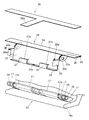
- FIG. 2 is a side view of the paper holder 1.
- FIG. 3 is a perspective view showing an elastic member 30, a holding piece 20, and a shaft support portion 17.
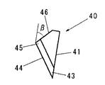
- FIG. 4 is a side view of the blade 40.
- FIG. 3 is a perspective view of a blade fixing member 50.
- FIG. 6 is a side view showing a mounting state of the blade fixing member 50 to the vertical surface portion 21. 6 is a side view showing the operation of the paper holder 1.
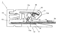
- FIG. 6 is a side view showing the operation of the paper holder 1.
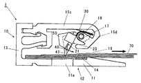
- FIG. 6 is a side view showing the operation of the paper holder 1.
- the paper holder 1 includes a case 10 and a holding piece 20 provided in the case 10.
- the case 10 is composed of a combination of two types of molded products having different cross sections, that is, a base portion 12 including a bottom surface portion 11 and an upper cover portion 15 located on the side facing the bottom surface portion 11. In combination, a paper insertion port 19 is formed on the front side.
- the base 12 and the upper cover 15 are formed of a hard synthetic resin material or the like.
- the size of the case 10 is not limited.
- the case 10 has a height of about 1.2 to 2 cm, a depth of about 3 to 5 cm, and a width of about 2.5 cm to 6 cm.
- a rear wall portion 13 is formed on the base portion 12 of the case 10 so as to rise substantially perpendicularly from the rear end thereof, and an upper cover portion 15 is locked to the rear wall portion 13.
- Protruding pieces 13b and 13c are formed on the inner surface of the rear wall portion 13 so as to protrude vertically from the upper end hook-shaped portion 13a at a slight distance.
- Locking portions 15 a and 15 b formed in two upper and lower stages are respectively locked and integrated at the rear end portion of the portion 15.
- the upper cover portion 15 has a planar upper surface portion 15c that faces the bottom surface portion 11 substantially in parallel with a space therebetween, and a front end front portion 15d that is substantially U-shaped in a side view at the front end of the upper surface portion 15c. Yes.
- a paper insertion port 19 is formed between the lower end of the front end front portion 15 d and the bottom surface portion 11.
- the lower end of the front end front portion 15d extends substantially horizontally in the paper insertion direction, and the tip portion 15e functions as a stopper that restricts the movement of the vertical surface portion 21 of the holding piece 20 described later in the paper drawing direction.
- a shaft support portion 17 for supporting a holding piece 20 to be described later from the front end front portion 15d to a U-shaped space (a space between the upper surface portion 15c and the front end front portion lower end portion. ) Protruding. That is, the shaft support portion 17 is located near the inner surface on the front end side of the upper surface portion 15c.
- the shaft support portion 17 is formed with a hole through which the shaft 18 can be inserted in the lateral direction (case width direction).
- slits 17a and 17a are formed on both sides in the width direction of the shaft support portion 17, and a mounting portion 22b of a holding piece 20 to be described later is inserted into the slits 17a and 17a.
- a friction portion 14 for preventing the inserted paper 70 from falling off is provided at least on the inner surface of the bottom surface portion 11 on the side of the insertion port 19 with respect to the distal end portion of the blade 40 described later. The friction portion 14 increases the friction force against the bottom surface portion 11 of the inserted paper to prevent the paper from falling off.
- the friction portion 14 is configured by attaching a sheet member such as rubber.
- the case 10 is made of a hard synthetic resin material, the base portion 12 in which the bottom surface portion 11 and the rear wall portion 13 rising from the rear end of the bottom surface portion 11 are integrally formed, and the rear wall portion.
- the upper cover portion 15 is detachably locked to the locking portion formed on the base plate 13 and integrated with the base portion 12.
- the base portion 12 and the upper cover portion 15 are reversed in the horizontal direction. It can be disassembled by sliding.
- the holding piece 20 is formed of, for example, a bent plate-like body having a required rigidity, and is rotatably supported by a shaft support portion 17 provided inside the front end front portion 15d.
- the vertical surface part 21 extended to the part 11 side is provided.
- the holding piece 20 can be formed of, for example, a metal plate such as an SK material or a stainless steel material having a thickness of about 0.1 to 0.3 mm.
- the holding piece 29 itself may have some elasticity, the holding piece 20 is manufactured so that the rigidity of the holding piece 20 is larger than that of the elastic member 30 described later during use (when the holding piece 20 rotates).
- the horizontal width of the holding piece 20 is about 2 to 4 cm as an example.
- the holding piece 20 is bent in a substantially U-shape when viewed from the side, and includes a horizontal surface portion 22 that is continuous with the vertical surface portion 21, and is supported by the shaft support portion 17 in the vicinity of the bent portion where the vertical surface portion 21 and the horizontal surface portion 22 intersect in a round shape. Has been.
- attachment portions 22 b and 22 b having shaft insertion holes 22 a for passing the shaft 18 are formed near the both end portions of the lateral surface portion 22 of the holding piece 20.
- the attachment portions 22b and 22b are inserted into the slits 17a and 17a formed in the shaft support portion 17, and the shaft 18 is passed through the hole of the shaft support portion 17 and the shaft insertion hole 22a of the attachment portion 22b, and a stopper 19 (silicone rubber).
- the holding piece 20 is pivotally supported by the pivotal support portion 17 by being stopped by an elastic cylindrical body or the like. Therefore, the holding piece 20 can be attached to and detached from the case 10.
- edge part (front-end front part side) of the horizontal surface part 22 is turned upside down and the folded part 24 and the groove part 25 are formed.
- One end of an elastic member (leaf spring 30), which will be described later, is inserted into and engaged with the groove 25.
- a lower end portion (bottom surface portion side) of the vertical surface portion 21 is bent toward the insertion direction side of the paper to form a bent portion 26, and a blade fixing member 50 described later is fixed to the bent portion 26.
- the A slit 26 a through which the blade fixed to the blade fixing member 50 is inserted is formed at the center in the width direction of the bent portion 26.
- the bent portion 26 serves as a vertical positioning portion for a blade fixing member 50 described later, and the slit 26 a serves as a lateral positioning portion for the blade 40 provided on the blade fixing member 50.
- the tip end portion 43 of the blade 40 protrudes from the end portion on the bottom surface side of the vertical surface portion 21 through the slit portion 26a.
- maintains the blade fixing member 50 in the predetermined position of the vertical surface part 21 of the holding piece 20 so that engagement / disengagement is possible.
- the blade fixing member 50 is bent from the end of the bent portion 26 to the tip in the direction along the vertical surface portion 21 as a locking means for detachably holding the blade fixing member 50 at a predetermined position in the vertical direction of the vertical surface portion 21.
- the locking part 27 in which the part 27a is formed is continuously provided.
- an upright locking portion in which a bent portion 28 a is formed at the tip from each end portion of the vertical surface portion 21. 28 is continuously provided.
- the elastic member 30 biases the spring force to the holding piece 20 in the paper drawing direction.
- the plate spring 30 is substantially T-shaped in plan view.
- the leaf spring 30 can be formed of a metal plate such as an SK material or a stainless steel material having a thickness of about 0.06 to 0.09 mm. By appropriately setting the width of the central strip 30a of the leaf spring 30, the spring force can be adjusted.
- the leaf spring 30 is disposed so as to be substantially along the inner surface of the upper surface portion 15 c of the upper cover portion 15 of the case 10, and a part (front portion) of the leaf spring 30 is inserted into the groove portion 22 of the holding piece 20 and engaged. is doing.
- the rear end portion (central strip portion) of the leaf spring 30 is locked to a locking portion 15f formed at the rear end of the inner surface of the upper surface portion 15c. Therefore, the elastic member 30 can be attached to and detached from the case 10.
- the blade 40 is preferably made of steel such as carbon tool steel (SK) used for the blade of a cutter knife.
- the thickness is usually about 0.3 to 1.2 mm.
- the blade 40 includes a back portion 41 that extends linearly, a blade edge (edge) 44 that intersects the back portion 41 to form a tip portion (point) 43 of an acute angle blade, and a back portion 41. It has a cutting edge 45 (the root of the cutting edge 44) at an opposing position, and an inclined side portion 46 that extends from the vicinity of the cutting edge 45 toward the back portion 41 in an inclined manner.
- the inclination angle ⁇ of the inclined side portion 46 is in the range of approximately 15 to 60 °.
- the angle of the tip portion 43 of the blade 40 is usually about 30 to 60 °.
- the length of the back part 41 of the blade 40 is, for example, about 6 to 12 mm.
- the blade fixing member 50 is a member that fixes the blade 40 and holds it at a predetermined position, and is attached to the vertical surface portion 21 of the holding piece 20.
- the blade fixing member 50 is provided with the blade 40 so that the tip portion 43 of the blade 40 protrudes. Further, the blade 40 is fixed to the blade fixing member 50 so as to maintain the vertical standing state of the blade 40 with respect to the surface of the vertical surface portion 21.
- the blade fixing member 50 has a base portion 52 having a flat surface portion (bottom surface portion) 51 fixed to the vertical surface portion 21 of the holding piece 20, and stands vertically from the base portion 52. It has a standing part 53 that holds the abdomen on both sides of the 40 abdomen (flat).
- the standing portion 53 has a height that matches the height of the blade 40.
- a slit 54 is formed along the contour of the blade 40 in the standing portion 53, and the blade 40 is inserted and fixed in the slit 54, and the vertical state of the blade 40 with respect to the base portion 52 is maintained.
- the blade fixing member 50 may be formed of a synthetic resin molded product.
- the blade fixing member 50 is fixed to the substantially central portion in the width direction and the inner surface on the insertion direction side of the vertical surface portion 21 of the holding piece 20 in the flat surface portion 51 of the base portion 52.
- the fixing member 50 is fixed by aligning the base portion 52 with the bent portion 26 at the lower end of the vertical surface portion 21.
- the blade 40 is fixed while maintaining a vertical standing state of the blade with respect to the surface of the vertical surface portion 21, passes through the slit 26 a of the vertical surface portion 21, and extends from the end on the bottom surface portion 11 side to the tip of the blade 40. 43 will be provided so as to protrude.
- the back portion 41 of the blade 40 is attached along the vertical surface portion 21.
- the blade 40 has a back portion 41 and a blade tip 44 that intersect to form a tip portion 43 of an acute-angled blade, and an inclined side portion 46 that extends from the vicinity of the blade base 45 toward the back portion 41 while being inclined.
- the blade 40 is reasonably disposed in the narrow internal space of the case, and the movement of the blade does not hinder the movement of the vertical surface portion 21 (the back portion).
- the holding piece 20 including the blade 40 operates reliably without the side facing 41 hitting the upper surface portion 15c of the elastic piece 20).
- a double-sided pressure-sensitive adhesive tape, an adhesive, or other appropriate fixing means can be used for fixing the blade fixing member 50 to the vertical surface portion 21.
- a concave groove portion 55 that can lock the locking portion 27 (bending portion 27 a) connected to the bent portion 26 of the vertical surface portion 21 is formed on the surface of the base portion 52.
- a tapered portion 56 with a thin tip is formed on the end side of the recessed groove portion 55 so that the blade fixing member 50 can be easily attached to the vertical surface portion 21 (the blade fixing member 50 has (Refer FIG. 5 which shows the mounting state to the vertical surface part 21).
- a plane-shaped through-hole (or recess) 11a is appropriately formed in the vicinity of the bottom surface portion 11 of the case 10 where the tip portion 43 of the blade 40 is located (only the vicinity of the portion has a cross section for convenience).
- the tip portion 43 of the blade 40 is housed in the space of the through hole 11a.
- the lower end of the front end front portion 15d extends substantially horizontally in the paper insertion direction, and the tip portion 15e is formed. Therefore, the movement of the vertical surface portion 21 of the holding piece 20 in the paper drawing direction is Since the portion 15e is regulated as a stopper, the tip portion 43 of the blade 40 does not contact the bottom surface portion 11 and is protected from damage or the like. Further, since the back portion 41 of the blade 40 is along the vertical surface portion 21 of the holding piece 20 and is arranged slightly inclined toward the paper insertion direction, the paper can be easily inserted.
- FIG. 6 shows a state in which the paper 70 is inserted from the insertion port 19 in the direction indicated by the arrow in the figure
- FIG. 7 shows a state in which the uppermost paper of the inserted paper 70 is pulled out.
- a plurality of paper sheets 70 are inserted into the case 10 from the insertion port 19 as appropriate.
- the front end portion of the paper 70 hits the front end portion 43 of the blade 40 lightly and further continues to be inserted against the spring force of the elastic member 30 on the insertion port side with respect to the holding piece 20, the paper 70 becomes more Enter inside.
- the vertical surface portion 21 of the holding piece 20 rotates in the direction of the drawing arrow (insertion direction side) from the position indicated by the broken line with the shaft support portion 17 as a fulcrum, and the spring force applied to the holding piece 20 is
- the front end portion 43 works to sandwich the paper 70 with the bottom surface portion 11.
- the distal end portion 43 of the blade 40 is in contact with the paper located at the upper part of the inserted paper 70 and is usually in a state of being slightly bitten and stuck. Accordingly, the paper 70 is held between the tip portion 43 and the bottom surface portion 11 of the blade 40 by using the spring force applied to the holding piece 20.
- the paper is pulled out from the insertion port 19 in the direction indicated by the arrow as shown in FIG.
- the holding piece 20 is slightly rotated in the direction of the drawing arrow (withdrawal direction side) with the shaft support portion 17 as a fulcrum.
- the tip end portion 43 of the blade 40 pierces not only the topmost paper but also the paper located below it (usually, for example, 2 to 5 sheets, for example, a plurality of sheets).
- the papers 70 other than the topmost paper are held by the tip portion 43 and the bottom surface portion 11 of the blade 40 and do not fall off, and only the topmost paper can be reliably pulled out. it can.
- the friction portion 14 effectively acts to prevent the other papers 70 from dropping off. Since the topmost paper that has been pulled out is pulled out with the leading end 43 of the blade 40 pierced, it reaches the front end side of the paper starting from the contact point where the leading end 43 of the blade 40 pierced. A straight, clean cutting line (trace) is formed. By repeating the above operation, paper can be taken out one sheet at a time easily and reliably.
- the installation place and installation means of the paper holder 1 are not limited.
- An adhesive tape or the like can be applied to the back surface of the case 10 (the outer surface of the bottom surface portion 11), and the case 10 can be installed on various wall portions.
- a plurality of paper holders 1 can be installed side by side on a horizontally long plate-like substrate.
Landscapes
- Sheet Holders (AREA)
- Knives (AREA)
- Details Of Rigid Or Semi-Rigid Containers (AREA)
- Perforating, Stamping-Out Or Severing By Means Other Than Cutting (AREA)
Abstract
Priority Applications (4)
| Application Number | Priority Date | Filing Date | Title |
|---|---|---|---|
| EP10839031.1A EP2517893A4 (fr) | 2009-12-24 | 2010-09-13 | Dispositif de retenue de papier |
| CN201080059182.XA CN103025537B (zh) | 2009-12-24 | 2010-09-13 | 纸架 |
| US13/518,273 US8839493B2 (en) | 2009-12-24 | 2010-09-13 | Paper holder |
| CA2785238A CA2785238A1 (fr) | 2009-12-24 | 2010-09-13 | Dispositif de retenue de papier |
Applications Claiming Priority (2)
| Application Number | Priority Date | Filing Date | Title |
|---|---|---|---|
| JP2009-293153 | 2009-12-24 | ||
| JP2009293153A JP4880028B2 (ja) | 2009-12-24 | 2009-12-24 | ペーパーホルダー |
Publications (1)
| Publication Number | Publication Date |
|---|---|
| WO2011077794A1 true WO2011077794A1 (fr) | 2011-06-30 |
Family
ID=44195342
Family Applications (1)
| Application Number | Title | Priority Date | Filing Date |
|---|---|---|---|
| PCT/JP2010/066114 Ceased WO2011077794A1 (fr) | 2009-12-24 | 2010-09-13 | Dispositif de retenue de papier |
Country Status (7)
| Country | Link |
|---|---|
| US (1) | US8839493B2 (fr) |
| EP (1) | EP2517893A4 (fr) |
| JP (1) | JP4880028B2 (fr) |
| KR (1) | KR20120099130A (fr) |
| CN (1) | CN103025537B (fr) |
| CA (1) | CA2785238A1 (fr) |
| WO (1) | WO2011077794A1 (fr) |
Cited By (2)
| Publication number | Priority date | Publication date | Assignee | Title |
|---|---|---|---|---|
| WO2012077441A1 (fr) * | 2010-12-07 | 2012-06-14 | エヌエスプランニング株式会社 | Distributeur de papier |
| WO2013141093A1 (fr) * | 2012-03-22 | 2013-09-26 | エヌエスプランニング株式会社 | Support de papier |
Families Citing this family (3)
| Publication number | Priority date | Publication date | Assignee | Title |
|---|---|---|---|---|
| AU2012202986A1 (en) * | 2012-05-21 | 2013-12-05 | Peter Hvala | Safety spike |
| KR101566251B1 (ko) * | 2014-06-24 | 2015-11-05 | 장금태 | 종이 클립 |
| CN117067675A (zh) * | 2023-09-06 | 2023-11-17 | 广东兴艺数字印刷股份有限公司 | 一种纸箱制造工艺及纸箱制造用刀模具、模切机 |
Citations (6)
| Publication number | Priority date | Publication date | Assignee | Title |
|---|---|---|---|---|
| JPH0271680U (fr) * | 1988-11-21 | 1990-05-31 | ||
| JP3085201B2 (ja) | 1996-07-30 | 2000-09-04 | トヨタ自動車株式会社 | 書類保持具 |
| JP2002120482A (ja) | 2000-08-07 | 2002-04-23 | Ns Planning Kk | カードホルダー |
| JP2005066859A (ja) * | 2003-08-26 | 2005-03-17 | Toshio Kaneshiro | クリップ |
| JP2008188915A (ja) * | 2007-02-06 | 2008-08-21 | Ns Planning Kk | ペーパーホルダー |
| WO2009116190A1 (fr) * | 2008-03-21 | 2009-09-24 | エヌエスプランニング株式会社 | Porte-papier |
Family Cites Families (12)
| Publication number | Priority date | Publication date | Assignee | Title |
|---|---|---|---|---|
| US2371713A (en) * | 1943-06-29 | 1945-03-20 | Prec Engineering Company Ltd | Card index |
| US3425389A (en) * | 1967-08-28 | 1969-02-04 | Gloria C Sacco | Place marker aid |
| US4241477A (en) * | 1979-08-16 | 1980-12-30 | John Freedom | Paper clip |
| DE3636640A1 (de) * | 1986-10-28 | 1988-05-11 | Licinvest Ag | Bildwechsler |
| US5193795A (en) * | 1987-11-21 | 1993-03-16 | Licinvest Ag | Device for the cyclic rearrangement of a pile of sheets |
| JPH0271680A (ja) * | 1988-09-07 | 1990-03-12 | Canon Inc | 撮像装置 |
| US5112083A (en) * | 1990-08-22 | 1992-05-12 | All-State Legal Supply Co. | Paper pad construction and clip means therefor |
| JPH1128882A (ja) * | 1997-07-09 | 1999-02-02 | Maruzen Seisakusho:Kk | メモ類のクリップ |
| US7076899B2 (en) * | 2001-03-28 | 2006-07-18 | Rose Displays, Ltd | Extruded grip frame arrangement |
| FR2824294B1 (fr) * | 2001-05-04 | 2003-09-26 | Artessa Sarl | Pince d'accrochage d'elements en forme de feuille |
| CN1400111A (zh) * | 2001-07-27 | 2003-03-05 | Ns设计公司 | 卡夹 |
| JP2010149360A (ja) * | 2008-12-25 | 2010-07-08 | Ns Planning Kk | ペーパーホルダー |
-
2009
- 2009-12-24 JP JP2009293153A patent/JP4880028B2/ja not_active Expired - Fee Related
-
2010
- 2010-09-13 US US13/518,273 patent/US8839493B2/en not_active Expired - Fee Related
- 2010-09-13 EP EP10839031.1A patent/EP2517893A4/fr not_active Withdrawn
- 2010-09-13 CA CA2785238A patent/CA2785238A1/fr not_active Abandoned
- 2010-09-13 KR KR1020127019422A patent/KR20120099130A/ko not_active Ceased
- 2010-09-13 CN CN201080059182.XA patent/CN103025537B/zh not_active Expired - Fee Related
- 2010-09-13 WO PCT/JP2010/066114 patent/WO2011077794A1/fr not_active Ceased
Patent Citations (7)
| Publication number | Priority date | Publication date | Assignee | Title |
|---|---|---|---|---|
| JPH0271680U (fr) * | 1988-11-21 | 1990-05-31 | ||
| JP3085201B2 (ja) | 1996-07-30 | 2000-09-04 | トヨタ自動車株式会社 | 書類保持具 |
| JP2002120482A (ja) | 2000-08-07 | 2002-04-23 | Ns Planning Kk | カードホルダー |
| JP3775222B2 (ja) * | 2000-08-07 | 2006-05-17 | エヌエスプランニング株式会社 | カードホルダー |
| JP2005066859A (ja) * | 2003-08-26 | 2005-03-17 | Toshio Kaneshiro | クリップ |
| JP2008188915A (ja) * | 2007-02-06 | 2008-08-21 | Ns Planning Kk | ペーパーホルダー |
| WO2009116190A1 (fr) * | 2008-03-21 | 2009-09-24 | エヌエスプランニング株式会社 | Porte-papier |
Non-Patent Citations (1)
| Title |
|---|
| See also references of EP2517893A4 * |
Cited By (6)
| Publication number | Priority date | Publication date | Assignee | Title |
|---|---|---|---|---|
| WO2012077441A1 (fr) * | 2010-12-07 | 2012-06-14 | エヌエスプランニング株式会社 | Distributeur de papier |
| WO2013141093A1 (fr) * | 2012-03-22 | 2013-09-26 | エヌエスプランニング株式会社 | Support de papier |
| JP2013193451A (ja) * | 2012-03-22 | 2013-09-30 | Ns Planning Kk | ペーパーホルダー |
| CN104203590A (zh) * | 2012-03-22 | 2014-12-10 | Gi技术公司 | 夹纸器 |
| CN104203590B (zh) * | 2012-03-22 | 2016-03-16 | Gi技术公司 | 夹纸器 |
| US9469147B2 (en) | 2012-03-22 | 2016-10-18 | Gi Technos Inc. | Paper holder |
Also Published As
| Publication number | Publication date |
|---|---|
| US20120260466A1 (en) | 2012-10-18 |
| CN103025537B (zh) | 2015-03-11 |
| US8839493B2 (en) | 2014-09-23 |
| EP2517893A1 (fr) | 2012-10-31 |
| JP4880028B2 (ja) | 2012-02-22 |
| JP2011131502A (ja) | 2011-07-07 |
| CN103025537A (zh) | 2013-04-03 |
| EP2517893A4 (fr) | 2015-08-12 |
| KR20120099130A (ko) | 2012-09-06 |
| CA2785238A1 (fr) | 2011-06-30 |
Similar Documents
| Publication | Publication Date | Title |
|---|---|---|
| JP4880028B2 (ja) | ペーパーホルダー | |
| EP2358241B1 (fr) | Dispositif d'accrochage | |
| US7832063B2 (en) | Paper holder | |
| WO2010073812A1 (fr) | Porte-papier | |
| WO2009116190A1 (fr) | Porte-papier | |
| WO2012077441A1 (fr) | Distributeur de papier | |
| JP4748619B2 (ja) | キャッチポップ | |
| WO2013141093A1 (fr) | Support de papier | |
| JP3130835U (ja) | 輪ゴムホルダ | |
| JP2009018134A (ja) | 片手で切れるトイレットペーパーカッター。 | |
| JP3206592U (ja) | 省力カッター | |
| KR200425196Y1 (ko) | 노트 스프링 속 끼움대 | |
| KR20120025077A (ko) | 자료 정리 홀더 | |
| JP3073039U (ja) | 粘着テープカッター | |
| US932203A (en) | Twine-cutter. | |
| KR200395792Y1 (ko) | 테이프컷터기 | |
| AU2016214837B2 (en) | Device for unrolling and cutting a strip | |
| US1166507A (en) | Note-paper holder. | |
| US916000A (en) | Combined paper holder and cutter. | |
| JP2015110436A (ja) | 物品収納ケースの取付け具 | |
| JP2004347808A (ja) | カード差し | |
| US1264980A (en) | Sales-slip holder. | |
| JP2010516378A (ja) | ロールタイプのトイレットペーパー(wastepaper)ホルダー | |
| KR20090016263A (ko) | 메모지 모듈 | |
| JP2007182045A (ja) | 薄片綴じ具 |
Legal Events
| Date | Code | Title | Description |
|---|---|---|---|
| WWE | Wipo information: entry into national phase |
Ref document number: 201080059182.X Country of ref document: CN |
|
| 121 | Ep: the epo has been informed by wipo that ep was designated in this application |
Ref document number: 10839031 Country of ref document: EP Kind code of ref document: A1 |
|
| WWE | Wipo information: entry into national phase |
Ref document number: 1432/MUMNP/2012 Country of ref document: IN |
|
| ENP | Entry into the national phase |
Ref document number: 2785238 Country of ref document: CA |
|
| WWE | Wipo information: entry into national phase |
Ref document number: 13518273 Country of ref document: US |
|
| WWE | Wipo information: entry into national phase |
Ref document number: 1201003173 Country of ref document: TH |
|
| NENP | Non-entry into the national phase |
Ref country code: DE |
|
| REEP | Request for entry into the european phase |
Ref document number: 2010839031 Country of ref document: EP |
|
| WWE | Wipo information: entry into national phase |
Ref document number: 2010839031 Country of ref document: EP |
|
| ENP | Entry into the national phase |
Ref document number: 20127019422 Country of ref document: KR Kind code of ref document: A |