WO2011077832A1 - 繊維強化樹脂の切断装置 - Google Patents
繊維強化樹脂の切断装置 Download PDFInfo
- Publication number
- WO2011077832A1 WO2011077832A1 PCT/JP2010/069173 JP2010069173W WO2011077832A1 WO 2011077832 A1 WO2011077832 A1 WO 2011077832A1 JP 2010069173 W JP2010069173 W JP 2010069173W WO 2011077832 A1 WO2011077832 A1 WO 2011077832A1
- Authority
- WO
- WIPO (PCT)
- Prior art keywords
- cutting
- reinforced resin
- laser
- cfrp
- fiber reinforced
- Prior art date
- Legal status (The legal status is an assumption and is not a legal conclusion. Google has not performed a legal analysis and makes no representation as to the accuracy of the status listed.)
- Ceased
Links
Images


Classifications
-
- B—PERFORMING OPERATIONS; TRANSPORTING
- B23—MACHINE TOOLS; METAL-WORKING NOT OTHERWISE PROVIDED FOR
- B23K—SOLDERING OR UNSOLDERING; WELDING; CLADDING OR PLATING BY SOLDERING OR WELDING; CUTTING BY APPLYING HEAT LOCALLY, e.g. FLAME CUTTING; WORKING BY LASER BEAM
- B23K26/00—Working by laser beam, e.g. welding, cutting or boring
- B23K26/14—Working by laser beam, e.g. welding, cutting or boring using a fluid stream, e.g. a jet of gas, in conjunction with the laser beam; Nozzles therefor
- B23K26/146—Working by laser beam, e.g. welding, cutting or boring using a fluid stream, e.g. a jet of gas, in conjunction with the laser beam; Nozzles therefor the fluid stream containing a liquid
-
- B—PERFORMING OPERATIONS; TRANSPORTING
- B23—MACHINE TOOLS; METAL-WORKING NOT OTHERWISE PROVIDED FOR
- B23K—SOLDERING OR UNSOLDERING; WELDING; CLADDING OR PLATING BY SOLDERING OR WELDING; CUTTING BY APPLYING HEAT LOCALLY, e.g. FLAME CUTTING; WORKING BY LASER BEAM
- B23K26/00—Working by laser beam, e.g. welding, cutting or boring
- B23K26/02—Positioning or observing the workpiece, e.g. with respect to the point of impact; Aligning, aiming or focusing the laser beam
- B23K26/06—Shaping the laser beam, e.g. by masks or multi-focusing
- B23K26/062—Shaping the laser beam, e.g. by masks or multi-focusing by direct control of the laser beam
- B23K26/0622—Shaping the laser beam, e.g. by masks or multi-focusing by direct control of the laser beam by shaping pulses
- B23K26/0624—Shaping the laser beam, e.g. by masks or multi-focusing by direct control of the laser beam by shaping pulses using ultrashort pulses, i.e. pulses of 1 ns or less
-
- B—PERFORMING OPERATIONS; TRANSPORTING
- B23—MACHINE TOOLS; METAL-WORKING NOT OTHERWISE PROVIDED FOR
- B23K—SOLDERING OR UNSOLDERING; WELDING; CLADDING OR PLATING BY SOLDERING OR WELDING; CUTTING BY APPLYING HEAT LOCALLY, e.g. FLAME CUTTING; WORKING BY LASER BEAM
- B23K26/00—Working by laser beam, e.g. welding, cutting or boring
- B23K26/36—Removing material
- B23K26/40—Removing material taking account of the properties of the material involved
-
- B—PERFORMING OPERATIONS; TRANSPORTING
- B23—MACHINE TOOLS; METAL-WORKING NOT OTHERWISE PROVIDED FOR
- B23K—SOLDERING OR UNSOLDERING; WELDING; CLADDING OR PLATING BY SOLDERING OR WELDING; CUTTING BY APPLYING HEAT LOCALLY, e.g. FLAME CUTTING; WORKING BY LASER BEAM
- B23K2103/00—Materials to be soldered, welded or cut
- B23K2103/50—Inorganic materials other than metals or composite materials
- B23K2103/52—Ceramics
Definitions
- the present invention relates to a cutting device suitable for use in cutting a fiber reinforced resin such as a carbon fiber reinforced resin.
- CFRP carbon fiber reinforced resin
- FRP processing by cutting using laser light is possible, but there is a problem that the processing cost increases. That is, in laser cutting, since the influence of heat by laser light is large, a carbonized layer or a heat-affected layer is formed on the FRP cut surface, and a high-quality cut surface cannot be obtained. Therefore, it is necessary to remove the carbonized layer and the heat-affected layer on the cut surface, and there is a problem that the processing cost becomes very high.
- KFRP Kevlar fiber reinforced resin
- This invention was made in order to solve said subject, Comprising: While suppressing the increase in process cost, providing the cutting device of the fiber reinforced resin which can suppress the quality fall of a cut surface is provided. Objective.
- the fiber reinforced resin cutting device includes a laser transmission unit that emits a laser beam to be irradiated to the fiber reinforced resin to be cut in a pulse shape, and the laser beam emitted from the laser transmission unit.
- a cutting head that emits to the resin, a pulse width in the laser light is 1 fs or more and 999 ps or less, and a relative moving speed of the cutting head with respect to the fiber reinforced resin is about 1.5 m / min or more. It is characterized by that.
- the thermal influence on the cut surface of the fiber reinforced resin can be reduced by shortening the pulse width of the laser light (from fs to ps unit length). Specifically, by increasing the energy density in the laser beam irradiated to the fiber reinforced resin, before the heat applied to the fiber reinforced resin irradiated with the laser beam is transmitted to the surroundings, the fiber reinforced resin Removed. Therefore, a carbonized layer is not formed on the cut surface of the fiber reinforced resin, and a region affected by heat can be reduced.
- the thermal influence on the cut surface of the fiber reinforced resin can be further reduced. Specifically, by increasing the moving speed of the region irradiated with the laser light in the fiber reinforced resin, the distance of heat transfer in the direction intersecting the cutting direction in the fiber reinforced resin is shortened. Thereby, the thermal influence in the cut surface of fiber reinforced resin becomes still smaller.
- a supply unit for supplying a liquid with increased pressure to the cutting head is further provided, and the cutting head ejects the liquid supplied from the supply unit to the fiber reinforced resin. It is desirable that a nozzle portion for guiding the laser beam is provided inside.
- the liquid is jetted onto the region of the fiber reinforced resin irradiated with the laser beam, that is, the cut surface. Then, since the area
- the shape accuracy of the cut surface of the fiber reinforced resin can be increased. That is, compared with the case where the liquid whose pressure is increased and the laser beam are ejected or irradiated from different directions, the accuracy of the width for cutting the fiber reinforced resin and the angle of the cut surface can be further increased.
- the liquid whose pressure has been increased is sprayed onto the area irradiated with the laser beam, the removal action of the fiber reinforced resin by the high pressure liquid is also added. Therefore, the cutting efficiency of the fiber reinforced resin can be increased as compared with the case where the liquid whose pressure is increased is not ejected.
- the fiber reinforced resin is cut using both the laser beam and the liquid whose pressure has been increased.
- Lower pressure liquids can be used compared to water jet cutting).
- the ability of the supply unit to increase the pressure of the liquid can be reduced, and it is not necessary to provide a soundproofing device that shields noise generated by the supply unit. In other words, the cost required for cutting the fiber reinforced resin can be reduced.
- the laser average output of laser light is about 400 W or more
- the pulse width is 1 fs or more and 999 ps or less
- the cutting speed is about 1.5 m / min or more, thereby reducing the processing cost.
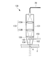
- FIG. 1 is a schematic diagram for explaining the outline of the cutting apparatus according to this embodiment.
- the cutting device 1 of this embodiment is used for cutting CFRP (fiber reinforced resin) 2 used as a material for aircraft, ships, and the like.
- the cutting device 1 is mainly provided with a laser transmission device (laser transmission unit) 10, a light guide unit 20, and a cutting head 30.
- the laser transmitter 10 emits laser light irradiated to the CFRP 2 in a pulse shape.
- the laser average output in the laser transmission device 10 is about 400 W or more
- the pulse width of the laser light emitted from the laser transmission device 10 is a length in units of fs to ps, preferably 1 fs or more and 999 ps or less.
- the length is desirably 100 fs or more and 900 fs or less.
- the light guide unit 20 is connected to the laser transmitting device 10 so that the laser beam can propagate.
- the laser transmission device 10 a known device can be used and is not particularly limited.
- the light guide 20 guides the laser beam emitted from the laser transmitter 10 to the cutting head 30.
- One end of the light guide 20 is connected to the laser transmitter 10, and the other end is connected to the cutting head 30.
- a known transmission path such as an optical fiber for guiding laser light can be used, and is not particularly limited.
- the cutting head 30 emits laser light to the CFRP 2 and moves relative to the CFRP 2.
- the light guide 20 is connected to the cutting head 30 so that the laser beam can propagate.
- the cutting head 30 is configured to be movable with respect to the CFRP 2.
- a moving mechanism (not shown) that moves the cutting head 30 with respect to the CFRP 2 at a speed of about 1.5 m / min or more is provided.
- the configuration of the cutting head 30 can be a known configuration that emits laser light, and is not particularly limited. Furthermore, the cutting head 30 and the CFRP 2 only need to be able to move relative to each other, and contrary to the present embodiment, the CFRP 2 may be configured to be movable with respect to the cutting head 30 and is not particularly limited.
- the laser transmission device 10 emits a laser beam having a laser average output of about 400 W or more and a pulse width of fs to ps units.
- the pulsed laser light enters the light guide 20 and is guided to the cutting head 30 by the light guide 20.
- the pulsed laser light guided to the cutting head 30 is irradiated from the cutting head 30 onto the cutting area in the CFRP2.
- the cutting head 30 is moved along the cutting direction at a speed of about 1.5 m / min with respect to the CFRP 2.
- FIG. 2 is a schematic diagram for explaining a state after cutting in the CFRP.
- the CFRP 2 in the region irradiated with the pulsed laser beam is removed by the laser beam.
- the amount of heat transmitted to the CFRP 2 adjacent to the region irradiated with the laser beam is small because the laser beam has a short pulse width, and a carbonized layer is not formed.
- the thickness of the influence layer 3 is suppressed to about 0.1 mm or less.
- FIG. 3 is a diagram for explaining the relationship between the laser average output of the laser light applied to the CFRP and the cutting speed of the CFRP.
- the average laser beam output of the laser beam is about 400 W or more and the cutting speed is about 1.5 m / min or more.
- the moving speed of the region irradiated with the laser light in the CFRP 2 becomes slow.
- the distance of heat transfer in the direction intersecting the cutting direction in the CFRP 2 is increased, and the thickness of the heat affected layer 3 is increased.
- a carbonized layer may be formed.
- the laser average output of the laser light is less than about 400 W, the ability to remove the CFRP2 of the laser light is lowered, and there is a possibility that the CFRP2 cannot be cut.
- the thermal influence on the cut surface of the CFRP 2 can be reduced by shortening the pulse width of the laser light (from fs to the length in ps unit). Specifically, by increasing the energy density of the laser light irradiated to the CFRP2, the CFRP2 is removed before the heat applied to the CFRP2 irradiated with the laser light is transmitted to the surroundings. Therefore, the carbonized layer is not formed on the cut surface of CFRP2, and the heat-affected layer 3 that is a region affected by heat can be reduced.
- the relative moving speed of the cutting head 30 with respect to the CFRP 2, in other words, the cutting speed of the CFRP 2 to about 1.5 m / min or more, the heat-affected layer 3 on the cut surface of the CFRP 2 can be further reduced.
- the distance of heat transfer in the direction intersecting the cutting direction in CFRP2 is shortened.
- the heat-affected layer 3 on the cut surface of the CFRP 2 can be further reduced, and an increase in processing cost can be suppressed and deterioration in the quality of the cut surface can be suppressed.
- FIG. 6 and FIG. 7 show image diagrams when roughing is performed.
- FIG. 2 shows a precision processing region 14 processed by the cutting / drilling method according to the present embodiment and a rough processing region 15 subjected to rough processing.
- FIG. 6 shows the case of drilling
- FIG. 7 shows the case of cutting.
- the roughing is performed at the processing speed and output conditions (output level and processing speed of the conventional method) of the roughing laser beam 16 that can cut and drill the CFRP 2 by single irradiation.
- the portion that may be affected by heat means the CFRP 2 that is located far from the final processing surface to such an extent that the heat-affected zone generated by rough processing does not reach the final processing surface. By doing so, it becomes easy to remove the cut CFRP2 from the processed portion. Moreover, the cutting area in consideration of the thermal effect can be reduced, and the processing time can be shortened.
- FIG. 4 is a schematic diagram for explaining the outline of the cutting apparatus according to the present embodiment.
- FIG. 5 is a schematic diagram illustrating the configuration of the cutting head of FIG. The same components as those in the first embodiment are denoted by the same reference numerals, and the description thereof is omitted.
- the cutting device 101 mainly includes a laser transmission device 10, a light guide unit 20, a high-pressure water supply device (supply unit) 140, a water supply path 150, and a cutting head 130. Is provided.
- the high-pressure water supply device 140 supplies pressurized water (liquid) to the cutting head 130.
- the high-pressure water supply device 140 is connected so that high-pressure water whose pressure is increased in the water supply path 150 can be circulated.
- the high-pressure water supply device 140 will be described as applied to a device that supplies water whose pressure has been increased to a pressure in a range from several MPa to several hundred MPa.
- a known device such as a pump for boosting water can be used, and it is not particularly limited.
- the water supply path 150 guides the water pressurized by the high pressure water supply device 140 to the cutting head 130.
- One end of the water supply path 150 is connected to the high-pressure water supply device 140 so that high-pressure water can flow, and the other end is connected to the nozzle portion 132 of the cutting head 130 so that high-pressure water can flow.
- a known one such as a pressure hose can be used, and is not particularly limited.
- the cutting head 130 emits laser light to the CFRP 2 and ejects high-pressure water. Further, the cutting head 130 is configured to be relatively movable with respect to the CFRP 2 in the same manner as the cutting head 30 in the first embodiment. As shown in FIG. 5, the cutting head 130 is mainly provided with a lens storage portion 131 and a nozzle portion 132.
- the lens housing part 131 constitutes the cutting head 130 together with the nozzle part 132.
- the lens housing part 131 is a member formed in a substantially cylindrical shape with one end closed, and a nozzle part 132 is connected to the end on the opening side so that laser light is incident.
- the light guide 20 is connected to the closed end of the lens housing 131 so that laser light is incident on the inside of the lens housing 131.
- a lens system 133 that condenses the laser light incident from the light guide unit 20 in the nozzle hole 134 in the nozzle unit 132 is provided inside the lens housing unit 131.
- the lens system includes a first lens 133A that converts laser light emitted from the light guide 20 into parallel light, and a second lens 133B that condenses the laser light converted into parallel light in the nozzle hole 134.
- the description is applied to an example in which 133 is configured.
- the nozzle part 132 irradiates the CFRP 2 with laser light incident from the lens housing part 131 and ejects high-pressure water to the CFRP 2.
- the nozzle part 132 is mainly provided with a nozzle hole 134, an inflow part 135, and a light guide window 136.
- the nozzle hole 134 guides laser light and high-pressure water toward the CFRP 2.
- the nozzle hole 134 is a through-hole formed inside the nozzle part 132, and one end part opens to the end part of the nozzle part 132 and the other end part opens to the inflow part 135.
- the nozzle part 132 is coated with gold on the inner peripheral surface.
- the inflow portion 135 is a space into which high-pressure water supplied from the water supply path 150 flows, and is a space that guides high-pressure water to the nozzle hole 134. Furthermore, the inflow portion 135 is also an optical path through which the laser light incident from the lens storage portion 131 passes when entering the nozzle hole 134.
- the inflow portion 135 is connected to the water supply passage 150 and the nozzle hole 134 so that high-pressure water can flow, and a light guide window 136 is disposed adjacent to the inflow portion 135.
- a light guide window 136, an inflow portion 135, and a nozzle hole 134 are arranged in order along the optical axis of the laser light and in the direction in which the laser light is irradiated.
- the water supply path 150 is connected from the direction intersecting the optical axis of the laser beam.
- the light guide window 136 allows the laser light to enter from the lens housing portion 131 and forms a space for the inflow portion 135.
- the light guide window 136 is a material that transmits laser light, and is a plate-like member formed of a material that can withstand the pressure of high-pressure water. Furthermore, one surface of the light guide window 136 constitutes a part of the surface of the nozzle part 132 adjacent to the lens storage part 131, and the other surface constitutes a part of the inner surface of the inflow part 135.
- the pulsed laser light is incident on the lens housing part 131 of the cutting head 130 via the light guide part 20.
- the laser light is emitted while diffusing from the end of the light guide 20 and enters the first lens 133A.
- Laser light is converted into parallel light by the first lens 133A and emitted, and then enters the second lens 133B.
- Laser light is condensed toward the nozzle hole 134 by the second lens 133B.
- the laser light emitted from the second lens 133B passes through the light guide window 136 and the inflow portion 135 and enters the nozzle hole 134.
- the laser light incident on the nozzle hole 134 is guided toward the CFRP 2 while reflecting the inner peripheral surface of the nozzle hole 134 coated with gold.
- the laser light guided through the nozzle hole 134 is irradiated from the end of the nozzle hole 134 on the CFRP2 side toward the CFRP2.
- the high-pressure water supply device 140 increases the pressure of water to a pressure in the range from several MPa to several hundred MPa, and the pressurized high-pressure water passes through the water supply path 150. And supplied to the nozzle portion 132 of the cutting head 130.
- the high-pressure water flows into the inflow portion 135 in the nozzle portion 132 and flows into the nozzle hole 134 from the inflow portion 135.
- the high-pressure water that has flowed into the nozzle hole 134 is guided toward the CFRP 2 by the nozzle hole 134 and is ejected toward the CFRP 2.
- the laser light and the high-pressure water are guided toward the CFRP 2 through the same path, in other words, coaxially.
- High pressure water ejected from the nozzle hole 134 flows into the cutting hole 4 formed in the CFRP 2.
- the nozzle part 132 close to the CFRP 2
- scattering of the ejected high-pressure water is suppressed.
- scattering of the laser beam irradiated to the CFRP 2 is prevented, and the inner surface of the cutting hole 4 can be reliably irradiated with the laser beam.
- the shape accuracy of the cut surface of the CFRP 2 can be increased. That is, compared with the case where high-pressure water and laser light are ejected or irradiated from different directions, the accuracy of the width for cutting the CFRP 2 and the angle of the cut surface can be further increased.
- CFRP2 when the plate thickness of CFRP2 is relatively thin, since CFRP2 is cut using both laser light and high-pressure water, compared with the case of cutting only with high-pressure water (in the case of water jet cutting). Lower pressure water can be used. As a result, the ability of the high-pressure water supply device 140 that increases the pressure of water can be reduced, and it is not necessary to provide a soundproofing facility that shields noise generated by the high-pressure water supply device 140. In other words, the cost required for cutting the CFRP 2 can be reduced.
- the plate thickness is greater than the cutting method using either one due to the cutting effect of high-pressure water and laser light.
- the thick CFRP 2 can be cut.
- the present invention has been described by applying the present invention to the cutting device 1 that cuts CFRP2.
- the invention is not limited to the cutting device 1 that cuts CFRP2, and various other FRPs such as KFRP are cut.
- the present invention may be applied to anything that is not limited.
Landscapes
- Physics & Mathematics (AREA)
- Optics & Photonics (AREA)
- Engineering & Computer Science (AREA)
- Plasma & Fusion (AREA)
- Mechanical Engineering (AREA)
- Laser Beam Processing (AREA)
Abstract
Description
本発明の繊維強化樹脂の切断装置は、切断対象である繊維強化樹脂に対して照射するレーザ光をパルス状に出射するレーザ発信部と、該レーザ発信部から出射されたレーザ光を前記繊維強化樹脂に対して出射する切断ヘッドと、が設けられ、前記レーザ光におけるパルス幅が1fs以上999ps以下であり、前記繊維強化樹脂に対する前記切断ヘッドの相対移動速度が約1.5m/min以上であることを特徴とする。
以下、本発明の第1の実施形態に係る切断装置ついて図1から図3を参照して説明する。
図1は、本実施形態に係る切断装置の概略を説明する模式図である。
本実施形態の切断装置1は、航空機や船舶等の材料として用いられるCFRP(繊維強化樹脂)2の切断に用いられるものである。
切断装置1には、図1に示すように、レーザ発信装置(レーザ発信部)10と、導光部20と、切断ヘッド30と、が主に設けられている。
本実施形態ではレーザ発信装置10におけるレーザ平均出力は約400W以上であり、レーザ発信装置10から出射されるレーザ光のパルス幅はfsからps単位の長さであり、好ましくは1fs以上999ps以下の長さ、より好ましくは100fs以上900fs以下の長さであることが望ましい。
レーザ発信装置10としては公知のものを用いることができ、特に限定するものではない。
導光部20としてはレーザ光を導く光ファイバ等の公知の伝送路を用いることができ、特に限定するものではない。
さらに本実施形態では、切断ヘッド30がCFRP2に対して移動可能に構成されている。例えば切断ヘッド30をCFRP2に対して約1.5m/min以上の速さで移動させる移動機構(図示せず)が設けられている。
さらに、切断ヘッド30とCFRP2とは相対移動が可能であればよく、本実施形態とは逆にCFRP2が切断ヘッド30に対して移動可能に構成されていてもよく、特に限定するものではない。
切断装置1を用いてCFRP2を切断する場合には、レーザ発信装置10からレーザ平均出力が約400W以上で、かつ、パルス幅がfsからps単位のパルス状のレーザ光が出射される。
パルス状のレーザ光が照射された領域のCFRP2はレーザ光により除去される。その一方で、レーザ光が照射された領域と隣接する部分のCFRP2に伝わる熱量は、レーザ光のパルス幅が短いため少なく炭化層は形成されず、図2に示すように、熱影響を受ける熱影響層3の厚さは約0.1mm以下に抑えられる。
上述のように、厚さが約5mmのCFRP2における切断面に炭化層が形成されず、熱影響層3の厚さが約0.1mm以下に抑えるには、図3に示すように、照射されるレーザ光のレーザ平均出力が約400W以上であり、かつ、切断速度が約1.5m/min以上であることが必要となる。
その一方で、レーザ光のレーザ平均出力が約400W未満となると、レーザ光のCFRP2を除去する能力が低下し、CFRP2を切断できなくなる可能性がある。
粗加工は、単回照射でCFRP2を切断・穴あけ加工できる粗加工用レーザ光16の加工速度及び出力の条件(従来法の出力レベル及び加工速度)で実施する。熱影響を受けても良い部分とは、粗加工によって発生する熱影響部が最終加工面に到達しない程度に最終加工面から離れた位置にあるCFRP2を意味する。そうすることによって、切断されたCFRP2を加工部から除去しやすくなる。また、熱影響を考慮した切断領域を小さくすることができ、加工時間を短縮することが可能となる。
次に、本発明の第2の実施形態について図4および図5を参照して説明する。
本実施形態の切断装置の基本構成は、第1の実施形態と同様であるが、第1の実施形態とは、レーザ光だけでなく昇圧された水も切断に用いられる点が異なっている。よって、本実施形態においては、図4および図5を用いてレーザ光および昇圧された水を用いた切断に係る構成のみを説明し、その他の構成要素等の説明を省略する。
図4は、本実施形態に係る切断装置の概略を説明する模式図である。図5は、図4の切断ヘッドの構成を説明する模式図である。
第1の実施形態と同一の構成要素には同一の符号を付して、その説明を省略する。
本実施形態では高圧水供給装置140を、数MPaから数百MPaまでの範囲の圧力に昇圧した水を供給するものに適用して説明する。
高圧水供給装置140としては、水を昇圧させるポンプ等の公知のものを用いることができ、特に限定するものではない。
水供給路150としては耐圧ホースなどの公知のものを用いることができ、特に限定するものではない。
切断ヘッド130には、図5に示すように、レンズ収納部131と、ノズル部132と、が主に設けられている。
レンズ収納部131は一方の端部が塞がれた略円筒状に形成された部材であって、開口側の端部には、レーザ光が入射されるようにノズル部132が接続されている。その一方で、レンズ収納部131における塞がれた端部には、導光部20がレンズ収納部131の内部にレーザ光を入射させるように接続されている。
本実施形態では導光部20から出射されたレーザ光を平行光に変換する第1レンズ133Aと、平行光に変換されたレーザ光をノズル孔134に集光させる第2レンズ133Bとからレンズ系133が構成されている例に適用して説明する。
ノズル部132には、ノズル孔134と、流入部135と、導光窓136と、が主に設けられている。
ノズル部132に内周面には金のコーティングが施されている。
導光窓136はレーザ光を透過する材料であって、高圧の水による圧力に耐えられる強度を有する材料から形成された板状の部材である。さらに導光窓136における一方の面は、ノズル部132におけるレンズ収納部131と隣接する面の一部を構成し、他方の面は流入部135の内面の一部を構成している。
切断装置101を用いてCFRP2を切断する場合には、図4に示すように、レーザ発信装置10から第1の実施形態の場合と同様にパルス状のレーザ光が出射される。
流入部135からノズル部132までの間では、レーザ光と高圧の水は同一の経路を介して、言い換えると同軸上でCFRP2に向かって導かれる。
例えば、上記の実施の形態においては、この発明をCFRP2を切断する切断装置1に適用して説明したが、CFRP2を切断する切断装置1に限られることなく、KFRPなどのその他各種のFRPを切断するものに適用してもよく、特に限定するものではない。
2 CFRP(繊維強化樹脂)
10 レーザ発信装置(レーザ発信部)
30,130 切断ヘッド
140 高圧水供給装置(供給部)
Claims (2)
- 切断対象である繊維強化樹脂に対して照射するレーザ光をパルス状に出射するレーザ発信部と、
該レーザ発信部から出射されたレーザ光を前記繊維強化樹脂に対して出射する切断ヘッドと、が設けられ、
前記レーザ光におけるパルス幅が1fs以上999ps以下であり、
前記繊維強化樹脂に対する前記切断ヘッドの相対移動速度が約1.5m/min以上である繊維強化樹脂の切断装置。 - 圧力を高めた液体を前記切断ヘッドに供給する供給部がさらに設けられ、
前記切断ヘッドには、前記供給部から供給された前記液体を前記繊維強化樹脂に対して噴出させるとともに、内部を前記レーザ光が導光されるノズル部が設けられている請求項1記載の繊維強化樹脂の切断装置。
Priority Applications (6)
| Application Number | Priority Date | Filing Date | Title |
|---|---|---|---|
| CA2779822A CA2779822A1 (en) | 2009-12-25 | 2010-10-28 | Cutting apparatus for fiber-reinforced plastics |
| CN2010800508269A CN102762333A (zh) | 2009-12-25 | 2010-10-28 | 纤维强化树脂的切割装置 |
| JP2011547384A JPWO2011077832A1 (ja) | 2009-12-25 | 2010-10-28 | 繊維強化樹脂の切断装置 |
| US13/505,052 US20120211476A1 (en) | 2009-12-25 | 2010-10-28 | Cutting apparatus for fiber-reinforced plastics |
| EP10839069A EP2517818A1 (en) | 2009-12-25 | 2010-10-28 | Cutting apparatus for fiber-reinforced resin |
| BR112012012122A BR112012012122A2 (pt) | 2009-12-25 | 2010-10-28 | aparelho de corte para plástico reforçados com fibras |
Applications Claiming Priority (2)
| Application Number | Priority Date | Filing Date | Title |
|---|---|---|---|
| JP2009296154 | 2009-12-25 | ||
| JP2009-296154 | 2009-12-25 |
Publications (1)
| Publication Number | Publication Date |
|---|---|
| WO2011077832A1 true WO2011077832A1 (ja) | 2011-06-30 |
Family
ID=44195377
Family Applications (1)
| Application Number | Title | Priority Date | Filing Date |
|---|---|---|---|
| PCT/JP2010/069173 Ceased WO2011077832A1 (ja) | 2009-12-25 | 2010-10-28 | 繊維強化樹脂の切断装置 |
Country Status (7)
| Country | Link |
|---|---|
| US (1) | US20120211476A1 (ja) |
| EP (1) | EP2517818A1 (ja) |
| JP (1) | JPWO2011077832A1 (ja) |
| CN (1) | CN102762333A (ja) |
| BR (1) | BR112012012122A2 (ja) |
| CA (1) | CA2779822A1 (ja) |
| WO (1) | WO2011077832A1 (ja) |
Cited By (3)
| Publication number | Priority date | Publication date | Assignee | Title |
|---|---|---|---|---|
| JP2015163660A (ja) * | 2014-02-28 | 2015-09-10 | 学校法人大同学園 | プリプレグの製造方法、プリプレグ、繊維強化熱可塑性樹脂の板材および繊維強化熱可塑性樹脂部材 |
| JPWO2016151776A1 (ja) * | 2015-03-24 | 2017-04-27 | 三菱電機株式会社 | レーザ加工方法、レーザ加工機、加工プログラム生成装置およびレーザ加工システム |
| JP2021154305A (ja) * | 2020-03-25 | 2021-10-07 | 日本製鉄株式会社 | 水冷用スプレーノズル、スプレーノズル用先端部材 |
Families Citing this family (7)
| Publication number | Priority date | Publication date | Assignee | Title |
|---|---|---|---|---|
| EP3251776B1 (en) * | 2016-06-02 | 2023-04-19 | Sandvik Intellectual Property AB | Method and apparatuses related to hole cutting |
| CN106975847B (zh) * | 2017-05-27 | 2018-09-25 | 南京工程学院 | 一种光纤脉冲激光诱导切割碳纤维复合材料的装置和方法 |
| US10987759B2 (en) * | 2017-05-31 | 2021-04-27 | Zhaoli Hu | Advanced back-strike protection process and related devices for water jet guided laser process |
| WO2020166670A1 (ja) * | 2019-02-13 | 2020-08-20 | 大学共同利用機関法人自然科学研究機構 | レーザ加工装置及びレーザ加工方法 |
| DE102020213934B4 (de) | 2020-11-05 | 2023-05-04 | Fraunhofer-Gesellschaft zur Förderung der angewandten Forschung eingetragener Verein | Verfahren zum Trennen von oder der Ausbildung eines Schnittspaltes in Faserverbund-Bauteilen mit Laserstrahlung |
| CN114986890A (zh) * | 2022-05-19 | 2022-09-02 | 深圳云疆智造科技有限公司 | 一种连续纤维3d打印喷头 |
| DE102025103474B3 (de) | 2025-01-30 | 2026-03-26 | Dr. Ing. H.C. F. Porsche Aktiengesellschaft | Verfahren zum Schneiden einer Bandage, die einen kohlefaserverstärkten Kunststoff umfasst |
Citations (4)
| Publication number | Priority date | Publication date | Assignee | Title |
|---|---|---|---|---|
| JPH0438741B2 (ja) | 1981-08-07 | 1992-06-25 | ||
| JPH06142961A (ja) * | 1992-11-13 | 1994-05-24 | Mitsubishi Heavy Ind Ltd | レーザによるfrp部材の切断、穴あけ加工方法 |
| JP2008006471A (ja) * | 2006-06-29 | 2008-01-17 | Sugino Mach Ltd | レーザ光線加工装置 |
| JP2009045911A (ja) * | 2007-08-23 | 2009-03-05 | Toyota Motor Corp | 多孔質材料の製造方法、多孔質膜の製造方法、高分子電解質の製造方法、多孔質材料、多孔質膜、高分子電解質膜、及び固体高分子型燃料電池 |
Family Cites Families (5)
| Publication number | Priority date | Publication date | Assignee | Title |
|---|---|---|---|---|
| CA2251243C (en) * | 1998-10-21 | 2006-12-19 | Robert Dworkowski | Distance tracking control system for single pass topographical mapping |
| CH702772B1 (de) * | 2004-12-21 | 2011-09-15 | Karl Merz | Verfahren zum Schneiden von Materialtafeln, insbesondere Metallblechen, sowie Schneidanlage zur Durchführung des Verfahrens. |
| WO2007072837A1 (en) * | 2005-12-20 | 2007-06-28 | Semiconductor Energy Laboratory Co., Ltd. | Laser irradiation apparatus and method for manufacturing semiconductor device |
| US20080067159A1 (en) * | 2006-09-19 | 2008-03-20 | General Electric Company | Laser processing system and method for material processing |
| CN201271782Y (zh) * | 2008-07-01 | 2009-07-15 | 北京大恒激光设备有限公司 | 随动式激光切割装置及使用该装置的激光切割机 |
-
2010
- 2010-10-28 CA CA2779822A patent/CA2779822A1/en not_active Abandoned
- 2010-10-28 BR BR112012012122A patent/BR112012012122A2/pt not_active IP Right Cessation
- 2010-10-28 JP JP2011547384A patent/JPWO2011077832A1/ja active Pending
- 2010-10-28 WO PCT/JP2010/069173 patent/WO2011077832A1/ja not_active Ceased
- 2010-10-28 US US13/505,052 patent/US20120211476A1/en not_active Abandoned
- 2010-10-28 EP EP10839069A patent/EP2517818A1/en not_active Withdrawn
- 2010-10-28 CN CN2010800508269A patent/CN102762333A/zh active Pending
Patent Citations (4)
| Publication number | Priority date | Publication date | Assignee | Title |
|---|---|---|---|---|
| JPH0438741B2 (ja) | 1981-08-07 | 1992-06-25 | ||
| JPH06142961A (ja) * | 1992-11-13 | 1994-05-24 | Mitsubishi Heavy Ind Ltd | レーザによるfrp部材の切断、穴あけ加工方法 |
| JP2008006471A (ja) * | 2006-06-29 | 2008-01-17 | Sugino Mach Ltd | レーザ光線加工装置 |
| JP2009045911A (ja) * | 2007-08-23 | 2009-03-05 | Toyota Motor Corp | 多孔質材料の製造方法、多孔質膜の製造方法、高分子電解質の製造方法、多孔質材料、多孔質膜、高分子電解質膜、及び固体高分子型燃料電池 |
Non-Patent Citations (1)
| Title |
|---|
| "Reports on the Topical Meeting of the Laser Society of Japan, 14 October 2009", vol. 393, 14 October 2009, article HIROKI INOUE ET AL.: "Laser machining of CFRP composites using a ultra short pulsed laser", pages: 21 - 22, XP008155330 * |
Cited By (4)
| Publication number | Priority date | Publication date | Assignee | Title |
|---|---|---|---|---|
| JP2015163660A (ja) * | 2014-02-28 | 2015-09-10 | 学校法人大同学園 | プリプレグの製造方法、プリプレグ、繊維強化熱可塑性樹脂の板材および繊維強化熱可塑性樹脂部材 |
| JPWO2016151776A1 (ja) * | 2015-03-24 | 2017-04-27 | 三菱電機株式会社 | レーザ加工方法、レーザ加工機、加工プログラム生成装置およびレーザ加工システム |
| JP2021154305A (ja) * | 2020-03-25 | 2021-10-07 | 日本製鉄株式会社 | 水冷用スプレーノズル、スプレーノズル用先端部材 |
| JP7526575B2 (ja) | 2020-03-25 | 2024-08-01 | 日本製鉄株式会社 | 水冷用スプレーノズル、スプレーノズル用先端部材 |
Also Published As
| Publication number | Publication date |
|---|---|
| CN102762333A (zh) | 2012-10-31 |
| BR112012012122A2 (pt) | 2019-09-24 |
| EP2517818A1 (en) | 2012-10-31 |
| CA2779822A1 (en) | 2011-06-30 |
| US20120211476A1 (en) | 2012-08-23 |
| JPWO2011077832A1 (ja) | 2013-05-02 |
Similar Documents
| Publication | Publication Date | Title |
|---|---|---|
| WO2011077832A1 (ja) | 繊維強化樹脂の切断装置 | |
| CN102292188B (zh) | 用于提高机加工过程可靠性的方法和装置 | |
| CN102837127B (zh) | 激光照射装置及激光照射方法 | |
| JP4997723B2 (ja) | ハイブリッドレーザ加工装置 | |
| US7211763B2 (en) | Photon energy material processing using liquid core waveguide and a computer program for controlling the same | |
| US9144861B2 (en) | Apparatus for laser peening hidden surfaces | |
| US20160288258A1 (en) | Laser light irradiation apparatus and laser peening treatment method | |
| KR101824553B1 (ko) | 레이저 가공 장치 및 레이저 가공 방법 | |
| JP2013215786A (ja) | レーザ加工装置、レーザ加工システム、レーザ加工方法 | |
| JP4977234B2 (ja) | レーザ衝撃硬化処理方法および装置 | |
| JP6797133B2 (ja) | レーザーピーニングに使用できる送出装置および関連する方法 | |
| CN100455398C (zh) | 基于激光冲击波技术的去除切削毛刺的装置 | |
| JP2014205170A (ja) | レーザ加工方法およびレーザ加工装置 | |
| CN113649707B (zh) | 一种SiC晶体的滚圆与参考面一次成型的加工方法 | |
| JP2012192420A (ja) | レーザ加工方法およびレーザ加工装置 | |
| EP3307473B1 (en) | Laser drilling method and system with laser beam energy modification to reduce back-wall strikes during laser drilling | |
| Gaebelein et al. | Pushing the envelope of liquid-jet guided laser machining applying modern IR fiber lasers | |
| CN204545723U (zh) | 一种旋转式水导激光加工系统 | |
| US6040551A (en) | Apparatus for hardening the inside contour of a gun barrel with laser radiation | |
| JP2006137998A (ja) | レーザ衝撃硬化処理方法および装置 | |
| JP6549878B2 (ja) | レーザ光照射装置およびレーザピーニング処理方法 | |
| WO2018135082A1 (ja) | レーザピーニング加工装置及びレーザピーニング加工方法 | |
| JP2012011409A (ja) | 複合材料部材の切断・穴あけ加工方法 | |
| JP6450038B2 (ja) | レーザピーニング加工装置及びレーザピーニング加工方法 | |
| JP2008049367A (ja) | レーザピーニング方法および装置 |
Legal Events
| Date | Code | Title | Description |
|---|---|---|---|
| WWE | Wipo information: entry into national phase |
Ref document number: 201080050826.9 Country of ref document: CN |
|
| 121 | Ep: the epo has been informed by wipo that ep was designated in this application |
Ref document number: 10839069 Country of ref document: EP Kind code of ref document: A1 |
|
| WWE | Wipo information: entry into national phase |
Ref document number: 2010839069 Country of ref document: EP |
|
| WWE | Wipo information: entry into national phase |
Ref document number: 2779822 Country of ref document: CA |
|
| WWE | Wipo information: entry into national phase |
Ref document number: 13505052 Country of ref document: US |
|
| WWE | Wipo information: entry into national phase |
Ref document number: 2011547384 Country of ref document: JP |
|
| NENP | Non-entry into the national phase |
Ref country code: DE |
|
| REG | Reference to national code |
Ref country code: BR Ref legal event code: B01A Ref document number: 112012012122 Country of ref document: BR |
|
| ENP | Entry into the national phase |
Ref document number: 112012012122 Country of ref document: BR Kind code of ref document: A2 Effective date: 20120521 |