WO2011078202A1 - Agrafeuse avec sertissage à plat - Google Patents
Agrafeuse avec sertissage à plat Download PDFInfo
- Publication number
- WO2011078202A1 WO2011078202A1 PCT/JP2010/073080 JP2010073080W WO2011078202A1 WO 2011078202 A1 WO2011078202 A1 WO 2011078202A1 JP 2010073080 W JP2010073080 W JP 2010073080W WO 2011078202 A1 WO2011078202 A1 WO 2011078202A1
- Authority
- WO
- WIPO (PCT)
- Prior art keywords
- anvil
- contact surface
- paper
- magazine
- bending
- Prior art date
- Legal status (The legal status is an assumption and is not a legal conclusion. Google has not performed a legal analysis and makes no representation as to the accuracy of the status listed.)
- Ceased
Links
Images


Classifications
-
- B—PERFORMING OPERATIONS; TRANSPORTING
- B25—HAND TOOLS; PORTABLE POWER-DRIVEN TOOLS; MANIPULATORS
- B25C—HAND-HELD NAILING OR STAPLING TOOLS; MANUALLY OPERATED PORTABLE STAPLING TOOLS
- B25C5/00—Manually operated portable stapling tools; Hand-held power-operated stapling tools; Staple feeding devices therefor
- B25C5/02—Manually operated portable stapling tools; Hand-held power-operated stapling tools; Staple feeding devices therefor with provision for bending the ends of the staples on to the work
- B25C5/0221—Stapling tools of the table model type, i.e. tools supported by a table or the work during operation
- B25C5/0242—Stapling tools of the table model type, i.e. tools supported by a table or the work during operation having a pivoting upper leg and a leg provided with an anvil supported by the table or work
- B25C5/025—Stapling tools of the table model type, i.e. tools supported by a table or the work during operation having a pivoting upper leg and a leg provided with an anvil supported by the table or work the plunger being manually operated
Definitions
- the present invention relates to a flat clinch type stapler for binding sheets.
- the conventional one forms a contact surface for guiding and bending the penetrating end of the spelling needle at the tip of the fixed anvil.
- This abutting surface is inclined with respect to the paper in the direction in which the tip of the spelling needle is guided inward. Therefore, at the final stage of bending, it is difficult to sufficiently press the root portion at the penetrating end portion of the spelling needle in the paper direction, and the spelling is completed with the root portion slightly swollen away from the paper. There is a problem that it becomes.
- the object of the present invention is to provide a flat clinch-type stapler that can solve the above-described problems and can bend and spell the spelling needle in a flat state without causing buckling or the like.
- the flat clinch type stapler includes a paper table for attaching paper to be bound, a magazine that holds the spelling needles arranged opposite to the paper table, and the spelling needles held in the magazine in the paper table direction.
- An anvil for folding the penetrating end portion of the spelling needle pushed out by the push blade and penetrating the paper by the folding contact surface or the molding contact surface, and during the folding operation by the anvil
- a contact surface switching mechanism for engaging the spelling needle with the bending contact surface and then engaging with the molding contact surface.
- paper refers to sheet-like materials in general, and includes paper, plastic, and cloth.
- the spelling needle can be folded and spelled flat without causing buckling or the like. That is, since the tip of the spelling needle can be guided by the bending contact surface, it is not necessary to set the inclination of the contact surface loosely in order to prevent buckling of the penetrating end of the spelling needle. Since the spelling needle after being engaged with the contact surface is engaged with the molding contact surface, the root portion at the penetrating end portion of the spelling needle can be sufficiently pressed in the paper direction at the final folding stage. For this reason, the problem that the spelling is completed in a state in which the root portion is slightly swollen away from the sheet is solved. Therefore, according to the present invention, the conventional dilemma can be eliminated at once, and the spelling needle can be folded and flattened without causing buckling or the like by a series of operations when binding the paper. .
- the anvil member includes a pair of an anvil member each having the bending contact surface and the molding contact surface, and the contact surface switching mechanism includes the anvil member.
- a structure in which the contact surface engaged with the spelling needle is switched from the contact surface for bending to the contact surface for molding can be given.
- the anvil has the anvil base rotatably supported by the two anvil members, and the abutment surface switching mechanism urges the two anvil members to contact and separate from each other. What was comprised so that it can do is considered as a preferable example.
- the contact surface switching mechanism may drive the anvil member using the movement of the paper table.
- the contact surface switching mechanism is configured such that the contact surface switching mechanism has an outer surface of the anvil member.
- the cam surfaces are formed on the side walls of the paper table so as to be in sliding contact with the cam surfaces, and the cam surfaces are pressed to urge both the anvil members toward each other when the paper table is depressed. Examples thereof include a pressing element and an elastic member that urges the two anvil members in the direction of separating them.
- Each anvil member preferably has a base end pivotally attached to the anvil base, and a bending contact surface and a molding contact surface formed continuously at the tip opposite the pressing blade.
- the folding contact surface is inclined with respect to the sheet in a direction in which the tip of the spelling needle is guided inwardly at a position where the anvil member is separated, and the molding contact surface is approached by the anvil member.
- a preferred embodiment is that the sheet is parallel to the sheet at the position.
- the anvil for folding the penetrating end of the spelling needle has a molding contact surface that molds the penetrating end of the spelling needle into a flat state at the final stage of the bending operation. It is.
- the present invention is configured as described above, it is possible to provide a flat clinch-type stapler that can be folded and spelled in a flat state without incurring buckling or the like.
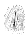
- the flat clinch type stapler includes a base 1, a paper table 3 that is pivotally attached to the base 1, and a paper table 3 that is to be bound, and is disposed so as to face the paper table 3.
- a magazine 5 that holds the needle N, a pressing blade 7 that pushes the spelling needle N held in the magazine 5 in the direction of the paper table 3, and a penetrating end of the spelling needle N that is pushed out by the pressing blade 7 and penetrates the paper P
- a contact surface switching mechanism 15 to be engaged with the molding contact surface 11 later.
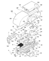
- the base 1 is formed of one piece of synthetic resin and is provided on the rear side of the inner wall 17 formed on the rear end side.
- a common pivot part 23 pivotally supporting the base end part 21 of the pressing blade base 19;
- a table pivoting part 25 provided on the front side of the inner wall 17 and pivotally supporting the base end part 24 of the paper table 3;
- a handle pivoting portion 27 is provided on an outer wall 26 formed outside the inner wall 17 and pivotally supports a handle 169 described later, and an anvil mounting portion 29 for mounting the anvil 13.
- a metal remover 31 is attached to the rear end of the base 1.
- the paper table 3 is made of metal made by bending a sheet metal material, and the base end portion 24 is pivotally attached to the table of the base 1.
- This paper table 3 has a rear end from the vicinity of the paper fixing position (F) where the rear end abuts on the rear stopper 35 provided on the base 1 to the submerged position (D) where the window 33 is close to the front end 69 of the anvil 13. It can be rotated in the vertical direction, and is biased in the paper fixing position (F) direction by a paper table spring 37 which is an elastic member held by the base 1.
- Locking contact portions 41 are formed on both side walls 39 of the paper table 3, and the locking contact portions 41 together with a lock support 45 constituting a table lock mechanism 43 described later together with the contact portions 41. It comes to contact.
- the lock support 45 includes a support body 51 in which a leg portion 47 protruding from the lower surface is engaged with a rail portion 49 of the base 1 so as to be slidable in the front-rear direction.
- the lock position (L) that prevents the lock contact portion 41 from moving downward, and the retreat position (S that allows the lock contact portion 41 to move downward).
- a spring accommodating portion 57 is provided after the support main body 51, and a lock support spring 53, which is an elastic member that urges the support main body 51 in the lock position (L) direction, is disposed in the spring accommodating portion 57. Yes.
- a support arm 59 extending rearward and having a rear end portion standing upward is integrally formed.
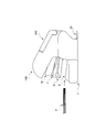
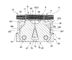
- the anvil 13 includes a pair of anvil members 61 each having the bending contact surface 9 and the molding contact surface 11. Specifically, both anvil members 61 are supported by an anvil base 63 attached to the base 1 so as to be pivotable in a direction of contacting and separating from each other via an anvil pin 65.
- the anvil member 61 has a thick plate shape, and a base end 67 is pivotally attached to the anvil base 63, and a bending contact surface 9 and a molding contact surface 11 are formed on a distal end 69 facing the pressing blade 7. Are formed continuously.
- the bending contact surface 9 is inclined with respect to the sheet P in a direction in which the tip N2 of the spelling needle N is guided inward at a position where the two anvil members 61 are separated from each other,
- the surface 11 is parallel to the paper P at a position where the two anvil members 61 approach each other.
- the anvil member 61 is made of metal, and the anvil base 63 is integrally formed of synthetic resin.
- Each anvil member 61 is urged in a direction away from each other by a leaf spring 71 as an elastic member provided below the anvil base 63.
- Reference numeral 73 denotes a locking wall for locking the locking projections 75 of the anvil members 61 at a predetermined separation position (S). That is, these anvil members 61 are regulated so as to be able to rotate between the separation position (S) and the approach position (C) that is in contact with or close to each other.
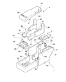
- the magazine 5 is for holding the spelling needle N disposed opposite to the paper table 3, and is made by bending a sheet metal material. It is a box-shaped thing opened upward. More specifically, the magazine 5 includes a bottom wall 79, a side wall 81 rising from both side edges of the bottom wall 79, and a front end wall 83 formed by bending the front end of the side wall 81. . A window 85 for pressing blade insertion is formed at the tip of the bottom wall 79. A projecting piece 87 formed by cutting and raising from the both side walls 81 is provided at an intermediate portion of the bottom wall 79.
- a protrusion 91 for restricting the forward movement of the slider 89 described later is provided in the middle of the bottom wall 79 at a position closer to the tip than the protruding piece 87.
- Shaft hole portions 93 are formed at the base end portions of the both side walls 81, and cylindrical magazine cover mounting shafts 95 are formed on the inner surfaces of the both side walls 81 so that the shaft centers coincide with the shaft hole portions 93. Is formed.
- outer rails 97 are provided on the outer surfaces of the side walls 81 so as to guide the slider 89 in a slidable manner.
- Pushers 99 are provided on the inner surfaces of the side walls 81 corresponding to the outer rails 97.
- An inner rail 101 for guiding the slidable guide is recessed.
- the shaft hole portion 93 is attached to the base 1 so that it can be rotated in the vertical direction by engaging the shaft-like protrusion 103 provided on the common pivot portion 23 of the base 1.
- the protruding piece 87 is inserted into the guide recess 105 formed on the inner surface of the inner wall 17 of the base 1 so as to be movable up and down.
- the upper movement of the magazine 5 with respect to the base 1 is locked at the upper limit position (U) that contacts the upper end of the guide recess 105.
- the magazine 5 is urged in the direction of the upper limit position (U) by a magazine spring 109 which is an elastic member held by the base 1.
- the slider 89 is for constituting a table lock mechanism 43, which will be described later, and is formed of synthetic resin as a single part. More specifically, the slider 89 is in the form of a channel that opens upward and includes a bottom wall 111 and side walls 113 that rise from both side edges of the bottom wall 111. On the outer surface of the both side walls 113, pins 115 for constituting the table lock mechanism 43 project from each other with their axes aligned with each other. A concave groove 117 is formed on the inner surface of the both side walls 113 to engage with the outer rail 97 of the magazine 5 so as to be slidable in the front-rear direction.
- a claw 119 that engages with the upper ends of the side walls 113 of the magazine 5 is formed at the upper edge portion of the inner surface of the side walls 113.
- a guide inclined surface 121 is formed for temporarily elastically deforming the side walls 113 outward when the slider 89 is engaged with the magazine 5 from below.
- the pusher 99 is for pressing a series of spelling needles N loaded in the magazine 5 in the direction of the tip N2, and is formed of a synthetic resin as a single part. More specifically, the front wall 123 for pressing the spelling needle N, the side walls 125 extending rearward from both side edges of the front wall 123, and the rear ends of the side walls 125 are provided. A ridge 129 is formed on the outer surface of the both side walls 125 so as to be slidable in the front-rear direction on the inner rail 101 of the magazine 5. On the lower surface of the protrusion 129, a guide inclined surface 131 is mainly formed for temporarily elastically deforming the side walls 125 when the pusher 99 is pushed into the magazine 5 from above.
- an extending wall 133 extending upward is formed at the upper edge portion on the rear side of one side wall 125, and the pusher spring 137 held by the magazine cover 135 is formed on the inner surface of the extending wall 133.
- a spring hook pin 139 is provided so as to hook the tip.
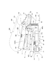
- the magazine cover 135 is arranged at a position where the upper surface opening 141 of the magazine 5 can be closed as shown in FIGS. 1, 2, 4 and 6 to 8, and is opened and closed when the spelling needle N is replenished. Then, it is a channel-like thing opened downward by making a sheet metal material. More specifically, the magazine cover 135 includes a top wall 143 and side walls 145 suspended from both side edges of the top wall 143. At the top end of the top wall 143, a projecting piece 151 is formed that engages with a recess 149 provided in the front end wall 83 of the magazine 5 at a closed position (C) that closes the upper surface opening 141 of the magazine 5.
- a first window 153 and a second window 155 are formed adjacent to each other in the vicinity of the tip of the top wall 143 through an intermediate wall 157.
- a hook 159 for hooking the base end of the pusher spring 137 is formed in the vicinity of the base end of the top wall 143.
- the intermediate wall 157 has a double wall structure in which a cut and raised piece formed when the windows 153 and 155 are punched and formed is folded back to the lower surface side of the top wall 143. Are formed so that both ends form a smooth arc.
- a bearing portion 161 having a semicircular arc shape is formed at the base end portion of the both side walls 145.
- the magazine cover 135 is attached to the magazine 5 so as to be openable and closable by engaging the bearing 161 with the magazine cover attachment shaft 95 of the magazine 5.
- the pusher spring 137 is a relatively long tension coil spring and extends forward along the bottom surface of the top wall 143 of the magazine cover 135 from the base end hung on the hook 159. By sequentially passing through one window 153 and second window 155, it is wound around the intermediate wall 157. Then, the pusher spring 137 slidably passing through the intermediate wall 157 is turned 180 degrees and extended rearward, and its tip is hooked on the spring hook pin 139 of the pusher 99. Therefore, the pusher 99 is elastically biased forward by the elastic force of the pusher spring 137.
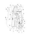
- FIG. 2 is a cross-sectional view of the present embodiment cut at the center in the left-right direction, but the pusher spring 137 is shown as a whole without being cut.
- the pressing blade 7 is used to push the spelling needle N held in the magazine 5 in the direction of the paper table 3.
- a pressing blade mounting portion 163 to be attached and a pressing blade main body 165 extending downward from the distal end side of the pressing blade mounting portion 163 are provided.
- the pressing blade 7 is made of metal made by bending a sheet metal material, and the pressing blade body 165 is inserted through a window 85 formed on the front end side of the magazine 5.
- the pressing blade base 19 holds the pressing blade 7 and can move forward and backward with respect to the magazine 5.
- a series of spelling needles N held in the magazine 5 are supplied one by one in the paper P direction for each reciprocation.
- the pressing blade base 19 is made of metal made by bending a sheet metal material, and its base end 21 is provided at the rear end of the base 1 and is the base end of the magazine 5. Is pivotally attached to a common pivot part 23 that pivots the frame.
- a cam follower 175 that engages with a cam groove 173 formed on the inner surface of the side wall 171 of the handle 169 is provided on the outer surface side of both side walls 167 of the pressing blade base 19.
- both side walls 167 of the pressing blade base 19 has a locking guide portion 177 constituting the table lock mechanism 43 together with the lock contact portion 41 and the lock support 45 of the paper table 3.
- the locking guide portion 177 has an inclined portion 179 extending upward to guide the pin 115 of the slider 89, and the pin 115 of the slider 89 when the lock is released when the lock is released.
- the top wall 182 of the pressing blade base 19 is provided with a slit 185 for attaching a pressing blade base spring 183 as an elastic member.
- the pressing blade base spring 183 is for urging the pressing blade base 19 in a direction away from the magazine 5.
- the end portion on the pressing blade base 19 side has a larger diameter than the end portion on the magazine 5 side. Conical coil spring.
- the handle 169 is for transmitting an operating force to the pressing blade base 19, and is formed of synthetic resin as a single part. More specifically, the handle 169 includes a top wall 187, side walls 171 depending from both side edges of the top wall 187, and a front wall 189 extending downward from the front edge of the top wall 187. Become. A storage space 191 for storing the spare spelling needle N is formed on the top surface of the top wall 187, and a cap 195 is attached to the upper surface opening 193 of the storage space 191 so as to be openable and closable. Yes.
- a rear end portion 196 of the side wall 171 is pivotally attached to a handle pivoting portion 27 provided on the base 1, and the handle 169 can rotate in the vertical direction with respect to the base 1.
- Cam grooves 173 for guiding the cam follower 175 of the pressing blade base 19 and transmitting the rotation of the handle 169 to the pressing blade base 19 are formed on the inner surfaces of the both side walls 171.
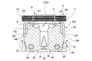
- the contact surface switching mechanism 15 includes a cam surface 199 provided on the anvil member 61 and a sliding contact with these cam surfaces 199, as shown in FIGS.
- the presser 201 formed on the paper table 3 and the leaf spring 71, which is an elastic member that urges both anvil members 61, are mainly configured.
- the contact surface switching mechanism 15 is configured to be able to turn and bias the anvil member 61 in the direction in which the anvil member 61 is contacted and separated.
- the movement of the paper table 3 is used.
- the anvil member 61 is driven.
- the contact surface switching mechanism 15 is formed on a cam surface 199 provided on the outer surface of the anvil member 61 and a side wall 39 of the paper table 3 so as to be in sliding contact with the cam surface 199.
- a pressing member 201 that presses the cam surface 199 to urge the two anvil members 61 toward each other during a subsidence operation, and a leaf spring 71 that is an elastic member that urges the two anvil members 61 to move away from each other. It is mainly composed.
- the lower edge portion of the side wall 39 functions as the presser 201.
- the table lock mechanism 43 is provided with a lock contact portion 41 provided on the paper table 3 and a lowering of the lock contact portion 41.
- a lock support 45 that moves forward and backward between a prohibited lock position (L) and a retracted position (S) that allows lowering, and a lock support spring that is an elastic member that urges the lock support 45 in the lock position (L) direction.
- 53 and an operation converting mechanism 55 that moves the lock support 45 in the direction of the retracted position (S) against the urging force of the lock support spring 53 by using the operation of driving the spelling needle N into the paper P. It becomes.
- the motion converting mechanism 55 includes a locking guide portion 177 provided on the pressing blade base 19, and a slider 89 that is guided by the guiding portion 177 and slides when the pressing blade base 19 approaches the paper table 3.
- the lock support 45 can be moved to the retracted position (S) by the sliding operation of the slider 89.
- the pin 115 of the slider 89 is positioned between the locking guide portion 177 of the pressing blade base 19 and the support arm 59 of the lock support 45, and the pressing blade base 19 rotates downward.
- the support arm 59 moves backward.
- the pressing blade base 19, the magazine 5, the paper table 3, and the anvil 13 are held at their initial positions. More specifically, the pressing blade base 19 is positioned above the magazine 5 while being urged in a direction away from the magazine cover 135 by the urging force of the pressing blade base spring 183. The magazine 5 is urged in a direction away from the base 1 by the urging force of the magazine spring 109, and an engaging projection 91 provided on the side wall 81 of the magazine 5 is formed in the guide recess 105 of the base 1. The upper limit position (U) that engages with the stepped portion is held.
- the paper table 3 is positioned at the paper fixing position (F) while being urged in a direction away from the base 1 by the urging force of the paper table spring 37.
- the anvil 13 is urged in a direction away from each other by the urging force of the leaf spring 71, and a locking projection 75 provided on each anvil member 61 is provided on the anvil base 63.
- the separated position (S) that engages with the work wall 73 is held.
- the paper P to be bound is attached on the paper table 3.
- the handle 169 is operated so as to approach the paper table 3
- the cam follower 175 of the pressing blade base 19 is moved along the cam groove 173 provided on the inner surface of the handle 169. While being guided toward the end side, the distance between the handle 169 and the pressing blade base 19 approaches.
- the magazine 5 approaches the paper table 3 side against the urging force of the magazine spring 109, and the pressing blade 7 is a window 85 provided in the magazine 5 along the inner surface of the wall on the front end side of the magazine 5. Move towards.
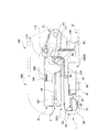
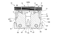
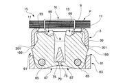
- the timing at which the tip N2 of the spelling needle N finishes penetrating to the back side of the paper P and the timing at which the locked state by the table lock mechanism 43 is released are set substantially at the same time. Therefore, when the handle 169 is further operated from the position where the spelling needle N is supplied from the magazine 5 toward the paper P as shown in FIG. 7, the locked state by the table lock mechanism 43 is released as shown in FIG. Then, the paper table 3 moves to the sinking position (D). In the process in which the paper table 3 moves to the sinking position (D), the tip N2 of the spelling needle N descends toward the tip 69 of the anvil member 61, and as shown in FIG. It contacts the contact surface 9.
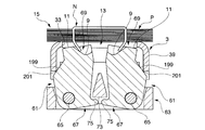
- the magazine 5 further approaches the paper table 3 side against the biasing force of the magazine spring 109, and the tip N2 of the spelling needle N gradually approaches as shown in FIGS.
- the anvil member 61 is moved inwardly by the bending contact surface 9 so that the penetrating end N1 of the spelling needle N is bent inward.
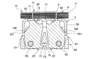
- the molding contact surface 11 of the anvil 13 comes into contact with the spelling needle N, and the molding needle is contacted by the molding contact surface 11.
- the N penetrating end N1 is pressed and molded in a flat state so as to be in close contact with the lower surface of the paper P.
- the locking contact portion 41 When the paper table 3 moves up to the vicinity of the paper fixing position (F), the locking contact portion 41 is retracted to a position outside the advance / retreat area of the lock support 45, and the lock support 45 is attached to the lock support spring 53. It self-returns to the lock position (L) by the force and enters an initial state.
- the flat clinch type stapler has the paper table 3 for attaching the paper P to be bound, and the magazine 5 that holds the spelling needle N that is disposed facing the paper table 3. And a pushing blade 7 for pushing the spelling needle N held in the magazine 5 in the direction of the paper table 3, and a penetrating end N1 of the spelling needle N pushed through the paper P and pushed by the pushing blade 7 for bending.
- An anvil 13 for bending by the contact surface 9 or the molding contact surface 11 and the molding contact surface after engaging the spelling needle N with the bending contact surface 9 during the folding operation by the anvil 13 11 is provided with the contact surface switching mechanism 15 that engages with 11, the spelling needle N can be bent and spelled in a flat state without causing buckling or the like. That is, since the tip N2 of the spelling needle N can be guided by the bending contact surface 9, there is no need to set the inclination of the contact surface loosely in order to prevent buckling of the penetrating end N1 of the spelling needle N.
- the root portion N 3 at the penetrating end N 1 of the spelling needle N is provided. Can be sufficiently pressed in the direction of the paper P. For this reason, the problem that the spelling is completed in a state where the root portion N3 slightly swells away from the paper P is solved.
- the anvil 13 since the anvil 13 includes the anvil member 61 that forms a pair with the bending contact surface 9 and the molding contact surface 11, only the bending contact surface 9 is provided. Compared to the conventional anvil 13, the spelling needle N can be made flat at the molding contact surface 11. In addition, it is not necessary to separately attach parts for molding in which the spelling needle N is bent and spelled in a flat state, and the number of parts can be reduced. Further, the anvil 13 is configured such that both the anvil members 61 are rotatably supported by the anvil base 63, and the contact surface switching mechanism 15 is urged to rotate in a direction in which the anvil member 61 is contacted and separated.
- Each anvil member 61 is formed by continuously forming the bending contact surface 9 and the molding contact surface 11 at the tip 69 facing the pressing blade 7, and is shown in FIGS. As described above, it is possible to perform the spelling operation by smoothly continuing the bending process and the molding process.
- the paper table 3 is not inadvertently pushed down. Therefore, the presser 201 formed at the lower end of the side wall 39 of the paper table 3 does not inadvertently press the cam surface 199 of the anvil member 61. That is, only when the lock of the table lock mechanism 43 is released, the paper table 3 moves downward and can perform a spelling operation.
- the abutment surface switching mechanism may move the anvil member relatively so as to be able to contact and separate by a linear motion such as a slide motion.
- the paper is not limited to paper as long as it is in sheet form, and may be a plastic sheet or cloth sheet. Also, the number of sheets is not limited to a relatively large number as illustrated, and may be one or a small number.
- the present invention is used for binding sheets, and can be used as a flat clinch-type stapler that can be folded and spelled in a flat state without causing buckling or the like.
Landscapes
- Engineering & Computer Science (AREA)
- Mechanical Engineering (AREA)
- Portable Nailing Machines And Staplers (AREA)
Abstract
L'invention concerne une agrafeuse avec sertissage à plat, munie d'une table (3) à papier servant à placer du papier (P) à relier ; un magasin (5) disposé face à ladite table (3) à papier et contenant des agrafes (N) ; une lame (7) de pression qui expulse les agrafes (N) en direction de la table (3) à papier, lesdites agrafes (N) étant contenues dans ledit magasin (5) ; une enclume (13) utilisée pour recourber les extrémités perforantes (N1) des agrafes (N) au moyen d'une surface (9) d'appui pour flexion et d'une surface (11) d'appui pour mise en forme, lesdites extrémités perforantes (N1) ayant été expulsées par la lame (7) de pression ayant perforé le papier (P) à relier ; et un mécanisme (15) de permutation des surfaces d'appui qui, pendant les opérations de déformation par ladite enclume (13), amène les agrafes (N) à interagir d'abord avec la surface (9) d'appui pour flexion, puis à interagir avec la surface (11) d'appui pour mise en forme.
Priority Applications (1)
| Application Number | Priority Date | Filing Date | Title |
|---|---|---|---|
| CN2010800591139A CN102666026A (zh) | 2009-12-25 | 2010-12-22 | 扁平钉脚型订书机 |
Applications Claiming Priority (2)
| Application Number | Priority Date | Filing Date | Title |
|---|---|---|---|
| JP2009294570A JP5521215B2 (ja) | 2009-12-25 | 2009-12-25 | フラットクリンチ型ステープラ |
| JP2009-294570 | 2009-12-25 |
Publications (1)
| Publication Number | Publication Date |
|---|---|
| WO2011078202A1 true WO2011078202A1 (fr) | 2011-06-30 |
Family
ID=44195729
Family Applications (1)
| Application Number | Title | Priority Date | Filing Date |
|---|---|---|---|
| PCT/JP2010/073080 Ceased WO2011078202A1 (fr) | 2009-12-25 | 2010-12-22 | Agrafeuse avec sertissage à plat |
Country Status (3)
| Country | Link |
|---|---|
| JP (1) | JP5521215B2 (fr) |
| CN (1) | CN102666026A (fr) |
| WO (1) | WO2011078202A1 (fr) |
Cited By (1)
| Publication number | Priority date | Publication date | Assignee | Title |
|---|---|---|---|---|
| EP3782459A1 (fr) * | 2019-08-23 | 2021-02-24 | Max Co., Ltd. | Machine de liaison |
Families Citing this family (4)
| Publication number | Priority date | Publication date | Assignee | Title |
|---|---|---|---|---|
| JP5862146B2 (ja) * | 2011-09-20 | 2016-02-16 | マックス株式会社 | ステープル及びステープラ |
| SE1300048A1 (sv) * | 2013-01-18 | 2014-07-19 | Isaberg Rapid Ab | Häftapparat |
| JP7651927B2 (ja) * | 2021-04-15 | 2025-03-27 | マックス株式会社 | ステープラ |
| CN114800392B (zh) * | 2021-11-01 | 2025-09-23 | 得力集团有限公司 | 一种平钉订书机的弯钉板及平钉订书机 |
Citations (2)
| Publication number | Priority date | Publication date | Assignee | Title |
|---|---|---|---|---|
| JPS6235779U (fr) * | 1985-08-19 | 1987-03-03 | ||
| JPH08500777A (ja) * | 1992-06-30 | 1996-01-30 | イサベルク・エービー | クリンチ機構付きステープラー |
Family Cites Families (2)
| Publication number | Priority date | Publication date | Assignee | Title |
|---|---|---|---|---|
| US6966479B2 (en) * | 2001-03-05 | 2005-11-22 | Kokuyo Co., Ltd. | Stapler |
| JP4144512B2 (ja) * | 2003-11-10 | 2008-09-03 | コクヨ株式会社 | ステープラ |
-
2009
- 2009-12-25 JP JP2009294570A patent/JP5521215B2/ja active Active
-
2010
- 2010-12-22 CN CN2010800591139A patent/CN102666026A/zh active Pending
- 2010-12-22 WO PCT/JP2010/073080 patent/WO2011078202A1/fr not_active Ceased
Patent Citations (2)
| Publication number | Priority date | Publication date | Assignee | Title |
|---|---|---|---|---|
| JPS6235779U (fr) * | 1985-08-19 | 1987-03-03 | ||
| JPH08500777A (ja) * | 1992-06-30 | 1996-01-30 | イサベルク・エービー | クリンチ機構付きステープラー |
Cited By (4)
| Publication number | Priority date | Publication date | Assignee | Title |
|---|---|---|---|---|
| EP3782459A1 (fr) * | 2019-08-23 | 2021-02-24 | Max Co., Ltd. | Machine de liaison |
| US11370096B2 (en) | 2019-08-23 | 2022-06-28 | Max Co., Ltd. | Binding machine |
| TWI825344B (zh) * | 2019-08-23 | 2023-12-11 | 日商美克司股份有限公司 | 捆束機 |
| AU2020220155B2 (en) * | 2019-08-23 | 2025-12-04 | Max Co., Ltd. | Binding machine |
Also Published As
| Publication number | Publication date |
|---|---|
| JP2011131353A (ja) | 2011-07-07 |
| JP5521215B2 (ja) | 2014-06-11 |
| CN102666026A (zh) | 2012-09-12 |
Similar Documents
| Publication | Publication Date | Title |
|---|---|---|
| JP5521215B2 (ja) | フラットクリンチ型ステープラ | |
| JP2009142937A (ja) | ステープラ | |
| US20140042203A1 (en) | Fastening device | |
| JP2013166206A (ja) | ステープラ | |
| JP4322014B2 (ja) | ホッチキス | |
| JP2013166208A (ja) | ステープラ | |
| JP2009012098A (ja) | ステープラ | |
| US20140231487A1 (en) | Stapler | |
| JP4826479B2 (ja) | ステープラ | |
| JP4001022B2 (ja) | ステープラ | |
| JP2017196729A (ja) | ステープラ | |
| JP6451254B2 (ja) | 綴じ装置 | |
| JP5080142B2 (ja) | ステープラ | |
| JP6645339B2 (ja) | ステープラ | |
| JP6614011B2 (ja) | ステープラ | |
| JP2009012094A (ja) | ステープラ | |
| JP6620485B2 (ja) | ステープラ | |
| JP5317036B2 (ja) | 什器用ストッパー | |
| WO2011078294A1 (fr) | Agrafeuse médicale | |
| JP2017193040A (ja) | ステープラ | |
| JP6330945B2 (ja) | ステープラ | |
| JP6332411B2 (ja) | ステープラ | |
| JP6031985B2 (ja) | ステープラ | |
| JP5181429B2 (ja) | 用紙押圧処理装置における用紙の支持機構 | |
| CN119523555A (zh) | 钉仓组件、吻合器及吻合器的安装方法 |
Legal Events
| Date | Code | Title | Description |
|---|---|---|---|
| WWE | Wipo information: entry into national phase |
Ref document number: 201080059113.9 Country of ref document: CN |
|
| 121 | Ep: the epo has been informed by wipo that ep was designated in this application |
Ref document number: 10839432 Country of ref document: EP Kind code of ref document: A1 |
|
| NENP | Non-entry into the national phase |
Ref country code: DE |
|
| 122 | Ep: pct application non-entry in european phase |
Ref document number: 10839432 Country of ref document: EP Kind code of ref document: A1 |