WO2011089986A1 - クランプ装置 - Google Patents
クランプ装置 Download PDFInfo
- Publication number
- WO2011089986A1 WO2011089986A1 PCT/JP2011/050619 JP2011050619W WO2011089986A1 WO 2011089986 A1 WO2011089986 A1 WO 2011089986A1 JP 2011050619 W JP2011050619 W JP 2011050619W WO 2011089986 A1 WO2011089986 A1 WO 2011089986A1
- Authority
- WO
- WIPO (PCT)
- Prior art keywords
- clamp rod
- annular piston
- clamp
- rod
- clamping device
- Prior art date
- Legal status (The legal status is an assumption and is not a legal conclusion. Google has not performed a legal analysis and makes no representation as to the accuracy of the status listed.)
- Ceased
Links
Images



Classifications
-
- B—PERFORMING OPERATIONS; TRANSPORTING
- B23—MACHINE TOOLS; METAL-WORKING NOT OTHERWISE PROVIDED FOR
- B23Q—DETAILS, COMPONENTS, OR ACCESSORIES FOR MACHINE TOOLS, e.g. ARRANGEMENTS FOR COPYING OR CONTROLLING; MACHINE TOOLS IN GENERAL CHARACTERISED BY THE CONSTRUCTION OF PARTICULAR DETAILS OR COMPONENTS; COMBINATIONS OR ASSOCIATIONS OF METAL-WORKING MACHINES, NOT DIRECTED TO A PARTICULAR RESULT
- B23Q3/00—Devices holding, supporting, or positioning work or tools, of a kind normally removable from the machine
- B23Q3/02—Devices holding, supporting, or positioning work or tools, of a kind normally removable from the machine for mounting on a work-table, tool-slide, or analogous part
- B23Q3/06—Work-clamping means
- B23Q3/069—Work-clamping means for pressing workpieces against a work-table
-
- B—PERFORMING OPERATIONS; TRANSPORTING
- B25—HAND TOOLS; PORTABLE POWER-DRIVEN TOOLS; MANIPULATORS
- B25B—TOOLS OR BENCH DEVICES NOT OTHERWISE PROVIDED FOR, FOR FASTENING, CONNECTING, DISENGAGING, OR HOLDING
- B25B5/00—Clamps
- B25B5/06—Arrangements for positively actuating jaws
- B25B5/061—Arrangements for positively actuating jaws with fluid drive
- B25B5/062—Arrangements for positively actuating jaws with fluid drive with clamping means pivoting around an axis parallel to the pressing direction
Definitions
- This invention relates to a clamp device configured such that a clamp rod is driven to go straight to a lock lowering position after being horizontally turned at a release ascending position.
- Patent Document 1 Japanese Utility Model Publication No. 60-182657.
- the prior art is configured as follows. An annular free piston is inserted between the cylinder hole of the cylinder tube and the piston rod. The straight end guide groove provided on the peripheral wall of the free piston is fitted with the inner end portion of the free piston rotation prevention pin, and the outer end portion of the rotation prevention pin is fixed to the cylinder tube. Further, a rotation guide groove is formed on the peripheral wall of the free piston so as to face the straight advance guide groove with the piston rod interposed therebetween. The outer end portion of the rotation pin is fitted into the rotation guide groove, and the inner end portion of the rotation pin is fixed to the piston rod. Further, a piston lowering restriction pin is fixed to the lower end of the piston rod. The piston lowering restriction pin is configured to be able to face the guide groove for the tightening stroke of the head cover fixed to the lower part of the cylinder tube.
- the piston rod (and the clamper) is switched from the release ascending position to the lock descending position according to the following procedure.
- the free piston descends straight along the linear guide groove.
- the rotation guide groove provided on the free piston causes the piston rod (and the clamper) to turn horizontally at the release ascending position via the rotation pin.
- both ends of the piston lowering restriction pin face the tightening stroke guide groove and the phase is matched, the piston rod (and the clamper) is locked down along the tightening stroke guide groove. It is driven straight ahead.
- both ends of the piston lowering restriction pin are always received by the upper part of the head cover by the lowering force acting on the piston rod from the free piston. For this reason, a large frictional resistance acts on both ends of the piston lowering restriction pin from the upper part of the head cover, and the turning resistance of the piston rod is large. Also, at the end of the turning of the piston rod, immediately before both phases of the piston lowering restriction pin and the tightening stroke guide groove coincide with each other, both ends of the piston lowering restriction pin are in the tightening stroke guide groove. Since the edge approaches the edge while turning, the bearing area of the edge gradually decreases.
- An object of the present invention is to provide a clamp device that can smoothly turn horizontally at a predetermined turning angle.
- the clamping device is configured as follows. That is, the clamp rod 7 inserted into the cylinder hole 6 of the housing 2 is configured to be driven straightly to the lock lowering position after being turned at the release upper position.
- An annular piston 13 is inserted between the cylinder hole 6 and the clamp rod 7 so as to be movable in the axial direction and rotatable about the axial center so as to be sealed.
- On one of the outer peripheral portion of the annular piston 13 and the inner peripheral wall of the cylinder hole 6, a guide groove 18 having a turning groove 23 and a rectilinear groove 24 provided in an upward direction is provided.
- an engagement tool 19 that fits into the guide groove 18 is provided on the other of the outer peripheral portion of the annular piston 13 and the inner peripheral wall of the cylinder hole 6.
- a transmission mechanism 26 is provided between the clamp rod 7 and the annular piston 13 to prevent the relative rotation of both of them around the axis and to allow relative movement in the axial direction.
- a lock working chamber 40 into which pressure fluid is supplied and discharged is formed above the annular piston 13. The diameter D1 of the clamp rod 7 in the portion sealed by the upper end wall 3a of the housing 2 is set to a value larger than the diameter D2 of the clamp rod 7 in the portion sealed by the annular piston 13.
- the present invention has the following effects, for example.
- the annular piston that is rotated through the swivel groove and the engagement tool swivels the clamp rod, so that a downward force is applied to the clamp rod.
- the present invention eliminates the need for the lower end wall of the clamp rod to be received by the lower end wall. As a result, a large frictional resistance does not act from the lower end wall of the housing to the lower portion of the clamp rod, the turning resistance of the clamp rod is reduced, and the clamp rod rod turns smoothly.
- a lock working chamber is provided on the upper side of the annular piston, and the diameter of the clamp rod in the portion sealed by the upper end wall of the housing is set to a value larger than the diameter of the clamp rod in the portion sealed by the annular piston. Since it is set, the clamp rod can be pushed up to the release ascending position by the vertical differential force acting on the clamp rod from the pressure fluid in the lock working chamber. As a result, the clamp rod can be securely held at the release ascending position by the differential force in the up and down direction, so that the positional accuracy of the height for turning the clamp rod horizontally is improved.
- the clamp rod can be held at the release ascending position by the pressure fluid in the lock operating chamber. Unlike the above-described conventional technique, it is not necessary to always receive the piston lowering restriction pin by the upper part of the head cover. The adverse effect that the edge of the guide groove for tightening stroke provided in the head cover collapses due to plastic deformation can be eliminated. For this reason, the clamp rod (and the clamp arm) surely turns at a predetermined turning angle, and then the lock is lowered. As a result, it is possible to reliably prevent a clamping error of an object to be fixed such as a workpiece.
- the clamp rod is turned by rotating the annular piston around the axis.
- the clamp rod (and the clamp arm) can be used even when the components change over time due to long-term use of the clamp device. It can be reliably turned. As a result, it is possible to reliably distinguish the turning operation and the locking operation of the clamping device.
- the clamp rod may be lowered while turning along with the turning down of the annular piston.
- the clamp arm fixed to the upper part of the clamp rod also descends while turning, causing a problem that the clamp arm interferes with other objects.
- the lower part of the clamp rod is lowered more than a predetermined amount by the cooperation of the lower part of the housing and the lower end wall of the housing that constitutes the malfunction prevention mechanism during the turning of the clamp rod. Since this can be prevented by the lower end wall of the housing, the occurrence of the above-described adverse effects can be prevented.
- the guide groove 18 is provided on the outer peripheral portion of the annular piston 13 and the engagement tool 19 is provided on the inner peripheral wall of the cylinder hole 6.
- the guide groove can be processed easily and accurately, so that a high-performance clamping device can be manufactured at low cost.
- the malfunction prevention mechanism M includes a fitting hole 52 provided in the lower end wall 5 of the housing 2 and a fitting portion 54 provided in the lower portion of the clamp rod 7.
- the fitting portion is configured to be prevented from being lowered by the peripheral wall 52a of the fitting hole 52 during turning at the release raised position, and to be fitted into the fitting hole 52 when the straight movement is lowered. 54.
- a malfunction prevention mechanism can be comprised simply.
- the fitting hole 52 and the fitting portion 54 in an oval shape in plan view, the malfunction prevention mechanism can be further simplified.
- a predetermined gap is formed between the upper surface of the peripheral wall 52a of the fitting hole 52 and the lower surface of the fitting portion 54.
- G is formed.
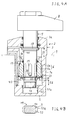
- FIG. 1A and 1B illustrate one embodiment of the present invention.
- FIG. 1A is a sectional view in an elevational view of a clamp device in a released state.
- FIG. 1B is a view corresponding to the cross-sectional view taken along the line BB in FIG. 1A. It is a transverse cross section of the important section of the above-mentioned clamp device. It is an expanded view of the outer peripheral part of the cyclic
- 4A and 4B show a state during switching of the clamping device, and are similar to FIGS. 1A and 1B, respectively.
- 5A and 5B show a locked state of the clamp device, which are similar to FIGS. 1A and 1B, respectively.
- the housing 2 includes a housing body 3 that is fixed to the base 1 by a plurality of bolts (not shown), and a lower end wall 5 that is provided at a lower portion of the housing body 3.
- a clamp rod 7 is inserted into the cylinder hole 6 of the housing 2.
- a clamp arm 8 is detachably fixed to the upper end of the clamp rod 7. Further, the upper portion of the clamp rod 7 is tightly and tightly fitted to the upper end wall 3 a of the housing body 3 via a sealing tool 9. Further, a flange 10 provided at an intermediate height portion of the clamp rod 7 can be rotatably received on the lower surface of the upper end wall 3a.
- the cylinder hole 6 includes a small-diameter hole 6a in the upper half and a large-diameter hole 6b in the lower half.
- the annular piston 13 is movable in the axial direction (here, up and down direction) via the outer seal 14 and the inner seal 15. It can rotate around its axis and is inserted in a tight manner.
- Three guide grooves 18 are formed on the outer peripheral portion of the annular piston 13 at substantially equal intervals in the circumferential direction.
- An engagement ball (engagement tool) 19 that fits into each guide groove 13 is provided on the inner peripheral wall of the small-diameter hole 6 a of the cylinder hole 6.
- Each engagement ball 19 is supported by a recessed hole 20 formed in the inner peripheral wall of the small diameter hole 6a.
- the guide groove 18 is formed by connecting the lower groove 22, the turning groove 23, and the rectilinear groove 24 upward.
- the inclination angle of the turning groove 23 is preferably within a range of 10 degrees to 30 degrees, and is set to about 20 degrees here.
- a transmission mechanism 26 is provided between the clamp rod 7 and the annular piston 13.
- the transmission mechanism 26 is arranged to prevent the clamp rod 7 and the annular piston 13 from rotating relative to each other around the axis and to allow relative movement in the axis direction. It is structured as follows. Three transmission grooves 27 extending in the vertical direction are formed at substantially equal intervals in the circumferential direction on the outer peripheral portion of the lower portion of the clamp rod 7.
- a transmission ball 28 fitted in each transmission groove 27 is provided on the annular piston 13.
- the transmission ball 28 is supported by the recess 31 of the annular piston 13 through a support plate 29 and a retaining ring 30.
- a driven portion 33 divided into left and right parts is fitted to a lower portion of the clamp rod 7 by a retaining ring 34.
- a lock working chamber 40 is formed between the upper end wall 3 a of the housing body 3 and the annular piston 13, and a lock port 42 communicates with the lock working chamber 40 via a pressure oil supply / discharge passage 41. Further, a release working chamber 43 is formed between the lower end wall 5 and the annular piston 13, and a release port 45 is communicated with the release working chamber 43 via another pressure oil supply / discharge passage 44.
- the diameter D1 of the portion sealed to the upper end wall 3a by the sealing tool 9 is the portion sealed to the annular piston 13 by the inner sealing tool 15. Is set to a value larger than the diameter D2.
- the pressure receiving cross-sectional area of the upper part of the clamp rod 7 becomes larger than the pressure receiving cross-sectional area of the lower part, and the clamp rod 7 is moved by the differential force acting from the pressure oil in the lock operating chamber 40. It is pushed up to the release raised position shown in FIG. 1A. That is, in this embodiment, a mechanism for holding the clamp rod 7 at the release rising position in the distal direction by the upward differential force acting on the clamp rod 7 is configured.
- the annular pressure receiving sectional area of the annular piston 13 is set so that the downward force acting on the annular piston 13 is larger than the upward differential force acting on the clamp rod 7.
- the lock working chamber 40, the release working chamber 43, and the annular piston 13 constitute a drive mechanism A that moves the annular piston 13 up and down.
- This malfunction prevention mechanism M that prevents the clamp rod 7 from lowering during turning of the clamp rod 7 at the release ascending position and allows the clamp rod 7 to descend at the time of lowering in a straight line described later. It is done.
- This malfunction prevention mechanism M is configured as follows.
- the lower end wall 5 of the housing 2 is provided with a circular accommodation hole 51 and a fitting hole 52 formed in an oval shape in the top and bottom in plan view.
- the lower end portion of the clamp rod 7 is provided with a fitting portion 54 formed in an oval shape in plan view, corresponding to the fitting hole 52.
- the long axis of the fitting portion 54 is orthogonal to the long axis of the fitting hole 52 (see FIG. 1B).
- a slight gap G is formed between the lower surface of the fitting portion 54 and the upper surface of the peripheral wall 52a of the fitting hole 52.
- the clamp device having the above-described configuration operates as follows. In the release state of FIG. 1, the pressure oil in the lock working chamber 40 is discharged and the pressure oil is supplied to the release working chamber 43. Thereby, the said annular piston 13 is raised. The clamp rod 7 is held at the release ascending position in FIG. 1A by an upward force acting on the pressure receiving cross-sectional area corresponding to the diameter D2.
- the annular piston 13 descends while turning in the clockwise direction in plan view along the turning groove 23 due to the pressure of the lock working chamber 40.
- the clamp rod 7 (and the clamp arm 8) held at the release ascending position is horizontally swiveled in the clockwise direction in plan view via the transmission ball 28 and the transmission groove 27.
- the clamp rod 7 (and the clamp arm 8) turns about 90 degrees, and the support plate is fixed to the lower portion of the annular piston 13. 29 contacts the driven part 33.
- the phases of the fitting portion 54 provided at the lower end of the clamp rod 7 and the fitting hole 52 are matched (see FIG. 4B), and the fitting hole 52 has the above-described phase.
- the fitting part 54 faces.
- the pressure of the lock working chamber 40 causes the annular piston 13 to descend straight along the rectilinear groove 24, and the annular piston 13 passes through the driven portion 33.
- the clamp rod 7 is lowered straight.
- the clamp rod 7 and the clamp arm 8 have been described in the state of full stroke downward, but the clamp arm 8 is configured to fix a workpiece (not shown) before full stroke. Is done.
- the pressure oil in the lock working chamber 40 may be discharged and the pressure oil supplied to the release working chamber 43 in the locked state shown in FIG. 5A.
- the clamping device operates in a procedure reverse to the above procedure. That is, first, as shown in FIG. 4A, the annular piston 13 and the clamp rod 7 rise straight due to the hydraulic pressure in the release working chamber 43, and the flange 10 of the clamp rod 7 is received by the upper end wall 3a. It is done. Next, as shown in FIG. 1A, the above-described annular piston 13 that rises while rotating rotates the clamp rod 7 in a counterclockwise direction in plan view.
- the turning down of the clamp rod 7 by a predetermined amount or more can be prevented by the fitting portion 54 being received by the peripheral wall 52a of the fitting hole 52 (FIG. 1 (B )), The occurrence of the above-mentioned adverse effects can be prevented.
- the above embodiment can be modified as follows.
- the turning angle of the clamp rod 7 is exemplified as about 90 degrees in the above embodiment, but can be set to a desired turning angle by changing the length of the turning groove 23 of the guide groove 18 in the inclination direction. is there.
- the turning direction of the clamp rod 7 (and the clamp arm 8) can be changed to the opposite direction to the exemplified turning direction by reversing the direction in which the guide groove 18 is inclined.
- three or four guide grooves 18 and engagement balls (engagement tools) 19 It may be one, two, or five or more.
- three or four transmission grooves 27 and transmission balls 28 of the transmission mechanism 26 are preferably provided, but may be one, two, or five or more.
- the transmission tool of the transmission mechanism 26 may be a key instead of the illustrated ball 28.
- the transmission groove 27 of the transmission mechanism 26 may be formed in a spline shape.
- the guide groove 18 may be provided on the inner peripheral wall of the cylinder hole 6 instead of being provided on the outer peripheral portion of the annular piston 13.
- a sleeve (not shown) in which a guide groove 18 is formed in the inner peripheral portion is fitted and fixed to the cylindrical hole of the housing body 3, and the small diameter hole 6a of the cylinder hole 6 is formed by the inner periphery of the sleeve. It is preferable to configure.
- the engagement ball (engagement tool) 19 is provided on the outer peripheral portion of the annular piston 13 instead of being provided on the inner peripheral wall of the cylinder hole 6.
- the fitting portion 54 is lightened on the upper surface of the peripheral wall 52a. You may make it contact.
- various modifications can be considered instead of the illustrated structure.
- the conventional technique Japanese Utility Model Publication No. 60-18267 described above can be used.
- the structure shown in FIGS. 2a and 2c may be used.
- the drive mechanism A for driving the annular piston 13 may be configured as follows instead of forming the working chambers 40 and 43 on the upper and lower sides of the annular piston 13. That is, the lock operating chamber 40 is formed on the upper side of the annular piston 13, and a spring chamber is formed on the lower side of the annular piston 13, and the above-described annular piston 13 is urged upward by a return spring attached to the spring chamber. To do.
- the working fluid of the clamping device may be a gas such as compressed air instead of a liquid such as pressurized oil.
- a gas such as compressed air instead of a liquid such as pressurized oil.
Landscapes
- Engineering & Computer Science (AREA)
- Mechanical Engineering (AREA)
- Jigs For Machine Tools (AREA)
Priority Applications (3)
| Application Number | Priority Date | Filing Date | Title |
|---|---|---|---|
| JP2011550894A JP5750053B2 (ja) | 2010-01-22 | 2011-01-17 | クランプ装置 |
| US13/522,607 US8777197B2 (en) | 2010-01-22 | 2011-01-17 | Clamping apparatus |
| EP11734592.6A EP2527082B1 (de) | 2010-01-22 | 2011-01-17 | Klemmvorrichtung |
Applications Claiming Priority (2)
| Application Number | Priority Date | Filing Date | Title |
|---|---|---|---|
| JP2010028151 | 2010-01-22 | ||
| JP2010-028151 | 2010-01-22 |
Publications (1)
| Publication Number | Publication Date |
|---|---|
| WO2011089986A1 true WO2011089986A1 (ja) | 2011-07-28 |
Family
ID=44306788
Family Applications (1)
| Application Number | Title | Priority Date | Filing Date |
|---|---|---|---|
| PCT/JP2011/050619 Ceased WO2011089986A1 (ja) | 2010-01-22 | 2011-01-17 | クランプ装置 |
Country Status (4)
| Country | Link |
|---|---|
| US (1) | US8777197B2 (de) |
| EP (1) | EP2527082B1 (de) |
| JP (1) | JP5750053B2 (de) |
| WO (1) | WO2011089986A1 (de) |
Cited By (5)
| Publication number | Priority date | Publication date | Assignee | Title |
|---|---|---|---|---|
| CN102357819A (zh) * | 2011-09-30 | 2012-02-22 | 中国三冶集团有限公司电气安装工程公司 | 一种t形槽工作台用于固定工件的装置及方法 |
| JP2014223714A (ja) * | 2013-05-15 | 2014-12-04 | 株式会社コスメック | 電動式クランプ装置 |
| JP2015223647A (ja) * | 2014-05-27 | 2015-12-14 | パスカルエンジニアリング株式会社 | クランプ装置 |
| WO2025037546A1 (ja) * | 2023-08-16 | 2025-02-20 | 株式会社コスメック | クランプ装置 |
| TWI921876B (zh) | 2023-08-16 | 2026-04-11 | 日商克斯美庫股份有限公司 | 夾鉗裝置 |
Families Citing this family (11)
| Publication number | Priority date | Publication date | Assignee | Title |
|---|---|---|---|---|
| CN103182648B (zh) * | 2011-12-29 | 2015-07-08 | 富泰华工业(深圳)有限公司 | 旋转气缸 |
| CN103792707B (zh) * | 2014-02-13 | 2016-04-13 | 北京京东方显示技术有限公司 | 支撑机台 |
| US8950741B1 (en) * | 2014-03-03 | 2015-02-10 | Praxis Industries, Llc | Clamping assembly |
| CN104493519A (zh) * | 2014-11-26 | 2015-04-08 | 柳州瑞明威罗动力机械有限公司 | 凸轮轴传感器座夹具及凸轮轴传感器加工方法 |
| FR3039447B1 (fr) * | 2015-07-31 | 2017-08-25 | Christophe Boiteux | Dispositif de serrage d'une piece sur un outillage |
| JP6590217B2 (ja) * | 2016-06-20 | 2019-10-16 | Smc株式会社 | シリンダ装置 |
| JP7127821B2 (ja) * | 2018-10-12 | 2022-08-30 | 株式会社コスメック | シリンダ装置 |
| ES3064882T3 (en) * | 2020-03-04 | 2026-04-29 | Metso Metals Oy | A pipe flange coupling device, a pipe assembly and a top-submerged-lance system |
| DE102020115803B4 (de) * | 2020-06-16 | 2024-03-21 | Ludwig Ehrhardt Gmbh | Schwenkspanner mit einem Übertragungsgetriebe |
| CN115229529A (zh) * | 2022-07-29 | 2022-10-25 | 湖南贝特新能源科技有限公司 | 涡旋压缩机用十字环加工夹具及工装 |
| JP2024121620A (ja) * | 2023-02-27 | 2024-09-06 | 株式会社コスメック | クランプ装置 |
Citations (3)
| Publication number | Priority date | Publication date | Assignee | Title |
|---|---|---|---|---|
| JPS6018267A (ja) | 1983-07-13 | 1985-01-30 | Mitsubishi Heavy Ind Ltd | 複合鋳造ロ−ルの製造方法 |
| JPS60123238A (ja) * | 1983-12-07 | 1985-07-01 | Howa Mach Ltd | クランプシリンダ |
| JPS63120048A (ja) * | 1986-11-07 | 1988-05-24 | Takashi Kimura | 回転ア−ム付自動締付装置 |
Family Cites Families (16)
| Publication number | Priority date | Publication date | Assignee | Title |
|---|---|---|---|---|
| US6017A (en) * | 1849-01-09 | Die for bending ttjbe-skelps | ||
| US3605569A (en) * | 1970-01-06 | 1971-09-20 | Allied Power Ind Inc | Fluid force applying device |
| GB1435027A (en) * | 1973-11-26 | 1976-05-12 | Spenklin Ltd | Power-operated work clamping devices |
| JPS6018267U (ja) | 1983-07-15 | 1985-02-07 | 株式会社日立製作所 | 燃料制御装置 |
| US5437440A (en) * | 1993-08-20 | 1995-08-01 | Compact Air Products, Inc. | Swing apparatus |
| JP3912763B2 (ja) * | 1999-10-13 | 2007-05-09 | 豊和工業株式会社 | クランプシリンダ |
| KR100371261B1 (ko) * | 1999-10-13 | 2003-02-06 | 호와고교 가부시키가이샤 | 클램프 실린더 |
| JP3588794B2 (ja) * | 1999-10-13 | 2004-11-17 | 豊和工業株式会社 | クランプシリンダ |
| JP3621082B2 (ja) * | 2001-11-13 | 2005-02-16 | 株式会社コスメック | 旋回式クランプ |
| TW579316B (en) * | 2001-11-13 | 2004-03-11 | Kosmek Ltd | Rotary clamp |
| JP4094340B2 (ja) * | 2002-02-13 | 2008-06-04 | 株式会社コスメック | クランプの動作検出装置 |
| TW544361B (en) * | 2002-04-03 | 2003-08-01 | Kosmek Kk | Rotary clamp |
| US6929254B2 (en) * | 2002-06-24 | 2005-08-16 | Phd, Inc. | Swing-arm clamp |
| US6908077B2 (en) * | 2002-09-26 | 2005-06-21 | Btm Corporation | Clamp with swinging and linear motion |
| US6902159B2 (en) * | 2003-08-21 | 2005-06-07 | Btm Corporation | Sealed pin locating and clamping apparatus |
| KR20090039672A (ko) * | 2006-06-13 | 2009-04-22 | 가부시키가이샤 코스멕 | 선회식 클램프 |
-
2011
- 2011-01-17 EP EP11734592.6A patent/EP2527082B1/de active Active
- 2011-01-17 WO PCT/JP2011/050619 patent/WO2011089986A1/ja not_active Ceased
- 2011-01-17 US US13/522,607 patent/US8777197B2/en active Active
- 2011-01-17 JP JP2011550894A patent/JP5750053B2/ja active Active
Patent Citations (3)
| Publication number | Priority date | Publication date | Assignee | Title |
|---|---|---|---|---|
| JPS6018267A (ja) | 1983-07-13 | 1985-01-30 | Mitsubishi Heavy Ind Ltd | 複合鋳造ロ−ルの製造方法 |
| JPS60123238A (ja) * | 1983-12-07 | 1985-07-01 | Howa Mach Ltd | クランプシリンダ |
| JPS63120048A (ja) * | 1986-11-07 | 1988-05-24 | Takashi Kimura | 回転ア−ム付自動締付装置 |
Cited By (5)
| Publication number | Priority date | Publication date | Assignee | Title |
|---|---|---|---|---|
| CN102357819A (zh) * | 2011-09-30 | 2012-02-22 | 中国三冶集团有限公司电气安装工程公司 | 一种t形槽工作台用于固定工件的装置及方法 |
| JP2014223714A (ja) * | 2013-05-15 | 2014-12-04 | 株式会社コスメック | 電動式クランプ装置 |
| JP2015223647A (ja) * | 2014-05-27 | 2015-12-14 | パスカルエンジニアリング株式会社 | クランプ装置 |
| WO2025037546A1 (ja) * | 2023-08-16 | 2025-02-20 | 株式会社コスメック | クランプ装置 |
| TWI921876B (zh) | 2023-08-16 | 2026-04-11 | 日商克斯美庫股份有限公司 | 夾鉗裝置 |
Also Published As
| Publication number | Publication date |
|---|---|
| JP5750053B2 (ja) | 2015-07-15 |
| EP2527082A4 (de) | 2016-03-30 |
| EP2527082B1 (de) | 2019-06-26 |
| US20120292843A1 (en) | 2012-11-22 |
| US8777197B2 (en) | 2014-07-15 |
| JPWO2011089986A1 (ja) | 2013-05-23 |
| EP2527082A1 (de) | 2012-11-28 |
Similar Documents
| Publication | Publication Date | Title |
|---|---|---|
| JP5750053B2 (ja) | クランプ装置 | |
| CN104470682B (zh) | 夹紧设备 | |
| EP2676766B1 (de) | Positionierungsvorrichtung | |
| WO2014077030A1 (ja) | 流体圧シリンダ及び旋回式クランプ装置 | |
| US9909600B2 (en) | Cylinder apparatus | |
| EP2849917B1 (de) | Verstellbare verbindungsklemme | |
| CN105813803B (zh) | 夹紧装置 | |
| JP2004003589A (ja) | 旋回式クランプ | |
| JP6795174B2 (ja) | スイング式クランプ装置 | |
| WO2018186136A1 (ja) | 旋回式クランプ | |
| JP2016209960A (ja) | ナットランナシステム | |
| WO2024070395A1 (ja) | 部材交換装置 | |
| JP2018043324A (ja) | 旋回式クランプ | |
| JP5227341B2 (ja) | クランプ装置 | |
| JP6222688B2 (ja) | 位置決め装置 | |
| JPWO2008126598A1 (ja) | リンク式クランプ装置 | |
| JPWO2010140554A1 (ja) | クランプ装置 | |
| JP4038108B2 (ja) | 旋回式クランプ | |
| WO2011037091A1 (ja) | ネジ係合式クランプ装置及びクランピングシステム並びに流体圧アクチュエータ | |
| JP4241100B2 (ja) | クランプ装置 | |
| JP4877787B2 (ja) | 位置決め装置およびその装置を備えた位置決めシステム | |
| JP6590217B2 (ja) | シリンダ装置 | |
| JP5760125B2 (ja) | 倍力機構付きシリンダ装置 | |
| JP4094339B2 (ja) | 旋回式クランプ | |
| JP4139427B2 (ja) | 旋回式クランプ |
Legal Events
| Date | Code | Title | Description |
|---|---|---|---|
| 121 | Ep: the epo has been informed by wipo that ep was designated in this application |
Ref document number: 11734592 Country of ref document: EP Kind code of ref document: A1 |
|
| DPE1 | Request for preliminary examination filed after expiration of 19th month from priority date (pct application filed from 20040101) | ||
| WWE | Wipo information: entry into national phase |
Ref document number: 2011550894 Country of ref document: JP |
|
| WWE | Wipo information: entry into national phase |
Ref document number: 13522607 Country of ref document: US |
|
| NENP | Non-entry into the national phase |
Ref country code: DE |
|
| WWE | Wipo information: entry into national phase |
Ref document number: 2011734592 Country of ref document: EP |