WO2011093224A1 - コネクタ及び電力給電システム - Google Patents
コネクタ及び電力給電システム Download PDFInfo
- Publication number
- WO2011093224A1 WO2011093224A1 PCT/JP2011/051092 JP2011051092W WO2011093224A1 WO 2011093224 A1 WO2011093224 A1 WO 2011093224A1 JP 2011051092 W JP2011051092 W JP 2011051092W WO 2011093224 A1 WO2011093224 A1 WO 2011093224A1
- Authority
- WO
- WIPO (PCT)
- Prior art keywords
- current
- plug
- connector
- current source
- power supply
- Prior art date
- Legal status (The legal status is an assumption and is not a legal conclusion. Google has not performed a legal analysis and makes no representation as to the accuracy of the status listed.)
- Ceased
Links
Images




Classifications
-
- H—ELECTRICITY
- H01—ELECTRIC ELEMENTS
- H01R—ELECTRICALLY-CONDUCTIVE CONNECTIONS; STRUCTURAL ASSOCIATIONS OF A PLURALITY OF MUTUALLY-INSULATED ELECTRICAL CONNECTING ELEMENTS; COUPLING DEVICES; CURRENT COLLECTORS
- H01R29/00—Coupling parts for selective co-operation with a counterpart in different ways to establish different circuits, e.g. for voltage selection, for series-parallel selection, programmable connectors
-
- H—ELECTRICITY
- H01—ELECTRIC ELEMENTS
- H01R—ELECTRICALLY-CONDUCTIVE CONNECTIONS; STRUCTURAL ASSOCIATIONS OF A PLURALITY OF MUTUALLY-INSULATED ELECTRICAL CONNECTING ELEMENTS; COUPLING DEVICES; CURRENT COLLECTORS
- H01R13/00—Details of coupling devices of the kinds covered by groups H01R12/70 or H01R24/00 - H01R33/00
- H01R13/66—Structural association with built-in electrical component
- H01R13/70—Structural association with built-in electrical component with built-in switch
- H01R13/703—Structural association with built-in electrical component with built-in switch operated by engagement or disengagement of coupling parts, e.g. dual-continuity coupling part
- H01R13/7036—Structural association with built-in electrical component with built-in switch operated by engagement or disengagement of coupling parts, e.g. dual-continuity coupling part the switch being in series with coupling part, e.g. dead coupling, explosion proof coupling
-
- H—ELECTRICITY
- H01—ELECTRIC ELEMENTS
- H01R—ELECTRICALLY-CONDUCTIVE CONNECTIONS; STRUCTURAL ASSOCIATIONS OF A PLURALITY OF MUTUALLY-INSULATED ELECTRICAL CONNECTING ELEMENTS; COUPLING DEVICES; CURRENT COLLECTORS
- H01R13/00—Details of coupling devices of the kinds covered by groups H01R12/70 or H01R24/00 - H01R33/00
- H01R13/66—Structural association with built-in electrical component
- H01R13/70—Structural association with built-in electrical component with built-in switch
- H01R13/71—Contact members of coupling parts operating as switch, e.g. linear or rotational movement required after mechanical engagement of coupling part to establish electrical connection
-
- H—ELECTRICITY
- H01—ELECTRIC ELEMENTS
- H01R—ELECTRICALLY-CONDUCTIVE CONNECTIONS; STRUCTURAL ASSOCIATIONS OF A PLURALITY OF MUTUALLY-INSULATED ELECTRICAL CONNECTING ELEMENTS; COUPLING DEVICES; CURRENT COLLECTORS
- H01R13/00—Details of coupling devices of the kinds covered by groups H01R12/70 or H01R24/00 - H01R33/00
- H01R13/46—Bases; Cases
- H01R13/53—Bases or cases for heavy duty; Bases or cases for high voltage with means for preventing corona or arcing
-
- H—ELECTRICITY
- H01—ELECTRIC ELEMENTS
- H01R—ELECTRICALLY-CONDUCTIVE CONNECTIONS; STRUCTURAL ASSOCIATIONS OF A PLURALITY OF MUTUALLY-INSULATED ELECTRICAL CONNECTING ELEMENTS; COUPLING DEVICES; CURRENT COLLECTORS
- H01R13/00—Details of coupling devices of the kinds covered by groups H01R12/70 or H01R24/00 - H01R33/00
- H01R13/66—Structural association with built-in electrical component
- H01R13/70—Structural association with built-in electrical component with built-in switch
- H01R13/703—Structural association with built-in electrical component with built-in switch operated by engagement or disengagement of coupling parts, e.g. dual-continuity coupling part
- H01R13/7031—Shorting, shunting or bussing of different terminals interrupted or effected on engagement of coupling part, e.g. for ESD protection, line continuity
- H01R13/7033—Shorting, shunting or bussing of different terminals interrupted or effected on engagement of coupling part, e.g. for ESD protection, line continuity making use of elastic extensions of the terminals
-
- H—ELECTRICITY
- H01—ELECTRIC ELEMENTS
- H01R—ELECTRICALLY-CONDUCTIVE CONNECTIONS; STRUCTURAL ASSOCIATIONS OF A PLURALITY OF MUTUALLY-INSULATED ELECTRICAL CONNECTING ELEMENTS; COUPLING DEVICES; CURRENT COLLECTORS
- H01R13/00—Details of coupling devices of the kinds covered by groups H01R12/70 or H01R24/00 - H01R33/00
- H01R13/66—Structural association with built-in electrical component
- H01R13/70—Structural association with built-in electrical component with built-in switch
- H01R13/703—Structural association with built-in electrical component with built-in switch operated by engagement or disengagement of coupling parts, e.g. dual-continuity coupling part
- H01R13/7031—Shorting, shunting or bussing of different terminals interrupted or effected on engagement of coupling part, e.g. for ESD protection, line continuity
- H01R13/7034—Shorting, shunting or bussing of different terminals interrupted or effected on engagement of coupling part, e.g. for ESD protection, line continuity the terminals being in direct electric contact separated by double sided connecting element
Definitions
- the present invention relates to a connector and a power supply system.
- the input is a low-impedance voltage power source, and the power from this voltage power source is distributed in parallel by using a pair of conductors.
- This AC distribution system is very natural when the power source is a voltage source, supplies a constant voltage to the load, and the power value is determined by the load current.
- LED Light Emitting Diode
- the power amount control that is, the brightness control
- LED lighting will continue to be used in the future. In order to connect such LED lighting to the current AC constant voltage system, constant current driving is performed after AC / DC conversion is performed inside the device.
- a current supply type distribution system that performs DC distribution is not necessarily effective for all electric devices, but a current supply type distribution system can be effective for certain current drive type devices.
- the current source and the load are connected in series. In principle, the current is constant, the voltage (of the supply source) is changed according to the number of loads, and the load sets its own terminal voltage appropriately. By doing so, the power is increased or decreased.
- the current supply type distribution system is considered as a dual of the voltage supply type distribution system that performs AC distribution.
- the power source is a voltage source in the voltage supply type distribution system, but is a current source in the current supply type distribution system.
- the constant parameter is a voltage in the voltage supply type distribution system, but a current in the current supply type distribution system.
- the connection of the load is parallel connection in the voltage supply type distribution system, but is connected in series in the current supply type distribution system.
- the connector electrode is always open with respect to the voltage in the voltage supply type distribution system, but it must be always closed with respect to the current in the current supply type distribution system. In a type distribution system, the switch is opened, but in a current supply type distribution system, the switch needs to be closed.
- an object of the present invention is to provide a new and improved power feeding system in which loads are connected in series and supplied with power from a power source, And providing a new and improved connector adapted for use in the power supply system.
- a connection portion is provided in series with a current source, and a plug is detachably connected thereto, and the connection portion is connected to the current source.
- Connected to a conducting wire through which a current flows and when the plug is not connected to the connection part, they are contacted with each other to short-circuit the current from the current source, and when the plug is connected to the connection part, the mutual contact is By releasing, the short circuit is released and the current from the current source is caused to flow to the plug, and when the connection of the plug is released from the connecting portion, they are contacted again to short-circuit the current from the current source.
- a connector is provided comprising a first terminal and a second terminal.
- the connector prevents the plug from being attached / detached when a plug is connected to the connecting portion, and the first terminal and the second terminal are connected when the plug is disconnected from the connecting portion. You may further provide the contact part made to contact.
- a plurality of sets of the first terminal and the second terminal may be provided in different directions with respect to the plug.
- a plurality of sets of the first terminal and the second terminal may be provided with different lengths.
- a direct current may be supplied from the current source.
- a current source for supplying a current for supplying a current
- a power receiving device for receiving a supply of current from the current source for receiving a supply of current from the current source
- a current from the current source are connected.
- a connector for supplying power to the power receiving device wherein the power receiving device is connected to the connector by a plug to receive current from the current source, and the connector is detachably connected to the plug.
- the connecting portion is connected to a conducting wire for passing a current from the current source, and when a plug is not connected to the connecting portion, the connecting portion is contacted with each other to short-circuit the current from the current source.
- the contact is released, so that the short circuit is released, and the current from the current source flows to the power receiving device to the plug, and the plug is connected from the connection portion.
- the shorting current from the current source is another contact again, the power feed system is provided.
- the power receiving device and the current source may perform transmission / reception of information with each other using the conductive wire.
- the DC power supply system may be supplied with a direct current from the current source.
- the power supply system further includes a detachable current source that is connected to the connector to supplement the current when current is supplied from the current source, and the detachable current source is connected to the connector at the time of connection.
- the switching operation may be performed in which the voltage is 0 and the voltage changes to a predetermined voltage after a predetermined time has elapsed after connection.
- a new and improved power feeding system in which loads are connected in series and supplied with power from a power source, and new and improved which are suitable for use in the power feeding system. Connector can be provided.
- FIG. 1 is an explanatory diagram showing a schematic configuration of a power supply system 1 according to the first embodiment of the present invention.
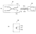
- FIG. 2 is an explanatory view showing a structural example of the connector 20 and the plug 100.
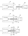
- FIG. 3 is an explanatory diagram showing a transition when the plug 100 is connected to the connector 20.
- FIG. 4 is an explanatory diagram illustrating a configuration example of the current load 30 including a power switch.
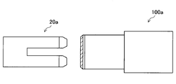
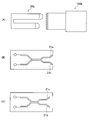
- FIG. 5 is an explanatory diagram illustrating another configuration example of the connector and the plug.
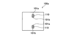
- FIG. 6 is an explanatory diagram when the plug 100a shown in FIG. 5 is viewed from the front.
- FIG. 7 is an explanatory diagram illustrating another configuration example of the connector and the plug.
- FIG. 1 is an explanatory diagram showing a schematic configuration of a power supply system 1 according to the first embodiment of the present invention.
- FIG. 2 is an explanatory view showing a structural example of the connector 20 and the plug 100.
- FIG. 3 is an explanatory diagram showing
- FIG. 8 is an explanatory diagram illustrating another configuration example of the connector and the plug.
- FIG. 9 is an explanatory diagram illustrating another configuration example of the connector and the plug.
- FIG. 10 is an explanatory diagram illustrating another configuration example of the connector and the plug.
- FIG. 11 is an explanatory diagram illustrating an application example of the power supply system 1.
- FIG. 12 is an explanatory diagram showing a configuration of the power supply system 2 according to the second embodiment of the present invention.
- FIG. 13 is an explanatory diagram illustrating an example of a general constant current circuit.
- FIG. 14 is an explanatory diagram showing an example in which a circuit that increases voltage without turning off current is realized by a semiconductor.
- FIG. 15 is an explanatory diagram showing the configuration of the power supply system 3 according to the third embodiment of the present invention.
- FIG. 16 is an explanatory diagram showing that the circuit unit including the voltage source 400 shown in FIG. 15 can be connected to the power feeding system 3 as appropriate.
- FIG. 17 is an explanatory
- FIG. 1 is an explanatory diagram showing a schematic configuration of a power supply system 1 according to the first embodiment of the present invention.
- the power supply system 1 includes a current source 10, a connector 20, and a current-type load 30.
- the current source 10 is a power source that outputs an alternating current or a direct current. In order to configure the power supply system 1 as shown in FIG. 1, it is practically preferable to output a direct current from the current source 10.
- the connector 20 is for connecting the current type load 30 to the power supply system 1 and has a connection part into which the plug 100 is inserted.
- This connection part is comprised including the electrodes 21a and 21b.
- the electrodes 21 a and 21 b are electrodes that are in a closed state when the current type load 30 is not connected to the connector 20. This is different from the voltage supply type distribution system in which the electrode is in an open state when no load (device) is connected.
- the current source load 30 has a plug 100 for connection to the power supply system 1.
- the plug 100 comes into contact with the electrodes 21 a and 21 b and can receive power from the current source 10.
- the plug 100 includes an insulator 110 for preventing a short circuit of an electrode (not shown in FIG. 1).
- the power supply system 1 When a plurality of loads are connected to the power supply system 1, the power supply system 1 is connected in series with the current source 10 as shown in FIG. 1.
- the current source 10 is preferably a constant current source that is controlled so that a constant current is maintained even when the number of loads connected to the power supply system 1 increases or decreases.
- FIG. 2 is an explanatory view showing a structural example of the connector 20 and the plug 100.
- FIG. 2A is an explanatory view showing a structural example of the connector 20 and the plug 100 in a cross-sectional view.
- FIG. 2B is an explanatory view of the plug 100 as viewed from the front.
- the connector 20 includes electrodes 21a and 21b.
- the plug 100 includes electrodes 101a and 101b and an insulator 110 that prevents a short circuit between the electrodes 101a and 101b.
- FIG. 3 is an explanatory diagram showing a transition when the plug 100 shown in FIG. 2 is connected to the connector 20. Although not shown in FIG. 3, the plug 100 is connected to some load that requires a current from the current source 10.
- FIG. 3A shows a state where the plug 100 is not connected to the connector 20. As shown in FIG. 3A, when the plug 100 is not connected to the connector 20, the electrodes 21a and 21b of the connector 20 are short-circuited.
- FIG. 3B illustrates a state where the plug 100 is inserted into the connector 20 partway. As shown in FIG. 3B, in a state where the plug 100 is inserted into the connector 20 halfway, the electrode 101a is connected to the electrode 21a and the electrode 101b is connected to the electrode 21b. Is still shorted.
- FIG. 3C shows a state in which the plug 100 is completely inserted into the connector 20.
- the electrode 101a is connected to the electrode 21a
- the electrode 101b is connected to the electrode 21b
- the electrodes 21a and 21b are short-circuited. Is released.
- the connector 20 and the plug 100 By configuring the connector 20 and the plug 100 as shown in FIG. 2A, instantaneous interruption of current in the current supply loop from the current source 10 in the power supply system 1 is eliminated, and the current-type load is added to the power supply system 1 30 can be connected or the current-type load 30 can be removed from the power supply system 1.
- the structure of the electrode on the connector side can be simplified if there is no problem even if a current interruption in the current supply loop from the current source 10 in the power supply system 1 occurs.
- FIG. 4 is an explanatory diagram showing a configuration example of a current-type load 30 including a power switch.
- the current load 30 shown in FIG. 4 is provided with a power switch 31 for controlling the reception of power supplied from the current source 10.
- the power switch 31 cuts off the supply of power supplied from the current source 10 to the inside of the current-type load 30 in a short-circuited state, and is supplied from the current source 10 in an open state. The supplied electric power is supplied to the inside of the current type load 30.
- the configuration of the connector and the plug for connecting to the power supply system 1 and receiving power supply is not limited to the above.
- another configuration example of the connector and the plug for connecting to the power supply system 1 and receiving power supply will be described.
- FIG. 5 is an explanatory diagram showing another configuration example of a connector and a plug for connecting to the power supply system 1 and receiving power supply.
- FIG. 5 shows the connector 20a and the plug 100a.
- the connector 20a serving as the female contact is divided into a plurality (two in the example of FIG. 5) and these are connected in parallel.
- FIG. 6 is an explanatory view of the plug 100a shown in FIG. 5 as viewed from the front.
- the plug 100a has a configuration in which two sets of the electrodes 101a and 101b and the insulator 110 that prevents the electrodes 101a and 101b from being short-circuited are provided.
- the connector 20a is configured to include the electrodes 21a and 21b as shown in FIG. 2A, and has a configuration including two sets of the electrodes 21a and 21b.
- the electrodes 21a and 21b are short-circuited, and the short-circuit between the electrodes 21a and 21b is released by the insertion of the plug 100a.
- FIG. 7 is an explanatory diagram showing another configuration example of a connector and a plug for connecting to the power supply system 1 and receiving power supply.
- FIG. 7A shows the connector 20b and the plug 100b.
- the connector 20b serving as the contact on the female side is divided into a plurality (two in the example of FIG. 5), and these are connected in parallel. The lengths of the electrodes serving as the contacts are made different.
- FIG. 7B and 7 (C) are explanatory views showing the structure of the electrodes provided inside the connector 20b.
- FIG. 7B illustrates the electrodes 21a and 21b provided on the upper side of the connector 20b shown in FIG. 7A
- FIG. 7C shows the bottom of the connector 20b shown in FIG. 7A.
- the electrodes 21c and 21d provided on the side are illustrated.
- the connectors 20a and 20b shown in FIGS. 5 and 7 realize a short circuit between the electrodes by the pressure contact force due to the elasticity of the electrodes.
- a configuration example for realizing the short circuit between the electrodes more efficiently will be described.
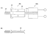
- FIG. 8A is an explanatory diagram showing another configuration example of a connector and a plug for connecting to the power supply system 1 and receiving power supply.
- FIG. 8A shows the connector 20c and the plug 100c.
- FIG. 8B is an explanatory diagram showing a cross section of the electrode 22 of the connector 20c shown in FIG.
- the plug 100c shown in FIG. 8A is provided with a protrusion 111 made of an insulator.
- the protrusion 111 has an action of pushing out the short-circuit contact 23 of the connector 20c.
- the connector 20c is provided with a spring 24 for short-circuiting the electrodes when the plug 100c is pulled out. Therefore, it is desirable that the connector 20c or the plug 100c be provided with a latch mechanism or a lock mechanism for overcoming the restoring force of the spring 24.
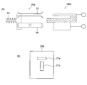
- FIG. 9A is an explanatory diagram showing another configuration example of a connector and a plug for connecting to the power supply system 1 and receiving power supply.
- FIG. 9A shows the connector 20d and the plug 100d.
- a connector 20d shown in FIG. 9 (A) is obtained by rotating one electrode of the connector 20c shown in FIG. 8 (A) 90 degrees about the longitudinal direction. In accordance with the rotation of one of the electrodes, the other electrode is also rotated 90 degrees around the longitudinal direction.
- FIG. 9B is an explanatory diagram showing an example of the shape of the cover of the connector 20d shown in FIG. 9A, and shows the connector 20a from the front.
- the polarity can be explicitly defined by changing the direction of one of the electrodes.
- the electrode arrangement is not limited to this example in order to explicitly define the polarity.
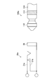
- FIG. 10 is an explanatory diagram showing another configuration example of a connector and a plug for connecting to the power supply system 1 and receiving power supply.
- FIG. 10 illustrates the connector 20d and the plug 100d.
- a connector 20d and a plug 100d shown in FIG. 10 are switch-equipped jacks and plugs that have been widely used in headphones and the like, and the wiring on the jack side is the wiring of the connector 20d shown in FIG. It can be used as a connector.
- the plug 100d includes a connection portion 112 that locks with the electrode 21a when inserted into the connector 20d, and an insulator 113 that is provided between the connection portion 112 and the electrode 114 and prevents a short circuit between the connection portion 112 and the electrode 114.
- the connector 20d and the plug 100d shown in FIG. 10 can be reduced in size and can be provided with polarity, and there is an effect that the plug 100d is provided with a self-holding force by the connection portion 112 that locks with the electrode 21a.
- FIG. 11 is an explanatory diagram illustrating an application example of the power supply system 1 according to the first embodiment of the present invention.
- FIG. 11 illustrates a current source 10, a connector 20, an LED illumination 200 as a current-type load, and a plug 100 for connecting the LED illumination 200 to the power supply system 1. It is assumed that there are appropriate numbers of LED lights 200, connectors 20, and plugs 100.
- the current value is set by the current source 10.
- the voltage across the LED illumination 200 is determined by the physical characteristics of the LED, and is about 2 to 4 V per one.
- the voltage of the voltage source should be approximately equal to the voltage determined by all the LED lights 200 connected in series. First, if the number of LED lights 200 is changed, the voltage needs to be readjusted every time the change is made, which is not practical. In the end, it must be a constant current source based on this voltage source.
- any number of LEDs can be driven with the same brightness (although the rated voltage of this unit varies).
- a power switch 31 as shown in FIG. 4 can be provided.
- the constant current supply is not limited to the application example of the power supply system 1 according to the first embodiment of the present invention shown in FIG. 11, and the constant current characteristic is maintained when the total voltage at the load end increases.
- the output terminal voltage of the current source 10 is increased. Therefore, when a certain voltage is exceeded, constant current supply can no longer be performed, and the current decreases. This is the same as in the constant voltage supply system, when the total current amount exceeds the specified value, the constant voltage characteristic cannot be maintained any more.
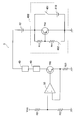
- FIG. 12 is an explanatory diagram showing the configuration of the power supply system 2 according to the second embodiment of the present invention. As shown in FIG. 12, the power supply system 2 according to the second embodiment of the present invention connects the current source 10, the connector 20, the current type load 300, and the current type load 300 to the power supply system 2. A plug 100 is shown.
- the current type load 300 includes a conversion circuit 301, a load control circuit 302, a load 303, a main switch 304, a communication circuit 310, and inductors L1, L2, and L3.
- the conversion circuit 301 includes a battery for storing electric power to be supplied to each part of the current-type load 300 inside, and converts the current (voltage generated at both ends) from the connector 100 to convert the load control circuit 302 and the communication circuit.
- a power supply voltage is supplied to circuits such as 310.
- the load control circuit 302 executes various controls for the load 303 and has a function of not only controlling the load 303 but also communicating the state of the load 303 to the outside.
- the load 303 is a current drive type load and consumes power supplied from the battery 301 or the current source 10.
- the main switch 304 is for controlling the power supply to the load 303. When the main switch 304 is in the closed state, the power supply to the load 303 is not performed, and when the main switch 304 is in the open state, the power to the load 303 is not supplied. Electric power will be supplied.
- the communication circuit 310 enables communication using a conducting wire of the power supply system 2 and includes an operational amplifier 311, an amplifier 312, and resistors R 1 and R 2.
- the inductors L1, L2, and L3 are current-type coupling circuits and are used for communication by the communication circuit 310.
- the current source 10 also has a communication function similar to that of the communication circuit 310, and performs communication between the current source 10 and the arbitrarily connected current type load 300. Thus, the state of the load 303 can be controlled and the state of the load 303 can be notified to the current source.
- the current type load 300 performs negotiation on the current source 10 and its supply contents before the main switch 304 is opened and power is supplied to the load 303.
- contents to be negotiated for example, since the load 303 is a current drive type, information on the voltage required by the load 303 may be used.
- the load control circuit 302 stores at least the conditions and standards at the start of the operation of the load 303. Note that the actual negotiation protocol and specific examples thereof are described in the above-mentioned Patent Document 2 and the like, and thus detailed description thereof is omitted.
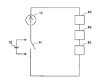
- FIG. 13 is an explanatory diagram illustrating an example of a general constant current circuit.
- FIG. 13 illustrates the current source 10, the switch 11, and a plurality of (here, three) loads 40.
- FIG. 14 is an explanatory diagram showing an example in which such a circuit is realized by a semiconductor.
- B of FIG. 14 is obtained by using a PNP transistor TR 2, resistors R11, and R12.
- a voltage equivalent to the voltage source 12 can be generated by appropriately selecting the values of the resistors R11 and R12.
- the arrow shown in FIG. 14 represents the direction of electric current.
- neither A nor B in FIG. 14 itself generates a voltage, but there is an external power supply, and it just looks like the voltage source 12 when current is supplied as shown by the arrow.
- the transistors TR 1 and TR 2 both appear to be diodes.
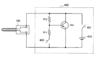
- FIG. 15 is an explanatory diagram showing the configuration of the power supply system 3 according to the third embodiment of the present invention.
- the power feeding system 3 according to the third embodiment of the present invention consists of a voltage source 12, a load 40, resistors R21, R22, R23, NPN transistor TR 0 and the operational amplifier 50. And a constant current circuit.
- the voltage source 400 is configured to include switches 401 and 402, a voltage source 410, comprise a PNP transistor TR 2, resistors R11, the R12.
- the switches 401 and 402 are initially open. When switch 401 is open state, appeared just diodes and PNP transistor TR 2, the voltage source 400 does not generate almost voltages as a whole.
- the PNP transistor TR 2 When the switch 402 is turned on from this state, the PNP transistor TR 2 operates as a circuit having the same potential difference as the voltage source 410. Therefore, when the switch 401 is subsequently turned on, the voltage source 410 becomes effective. Finally, the voltage source 410 is connected to the power supply system 3 by turning off the switch 402. Note that if you turn off the 402 at this time, the PNP transistor TR 2 for voltage source 410 is reverse biased, the PNP transistor TR 2 is invisible to the diode.
- FIG. 16 is an explanatory diagram showing that the circuit unit including the voltage source 400 shown in FIG. 15 can be connected to the power supply system 3 as appropriate.
- the voltage source 400 includes switches 401 and 402 inside, and both are open before being connected to the power supply system 3.
- This unit is provided with a plug 100 for series connection.
- a potential difference corresponding to one diode is generated at both ends of the plug 100.
- the switch 402 is subsequently turned on, the potential difference between the both ends of the plug 100 becomes a potential corresponding to the voltage source 410, and then the actual voltage source 410 is turned on the power feeding system 3 by turning on the switch 401. Connected.
- the voltage source 400 is connected to the connector (for example, the connector 20 shown in FIG. 1), it is necessary to sequentially control the opening and closing of the switches 401 and 402.
- a structure may be provided in which the switches 401 and 402 are operated sequentially by rotating the plug 100 after being inserted into the connector.
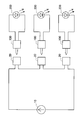
- An electric vehicle incorporating a drive motor in a wheel requires at least two motors for driving the wheel. When both front and rear wheels are driven, four are required, and the number varies depending on the number of wheels to be driven.
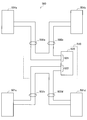
- FIG. 17 is an explanatory diagram showing a configuration of an electric vehicle 500 according to the fourth embodiment of the present invention.
- FIG. 17 shows the connection between the motor and the control circuit in consideration of practicality.
- the front wheels 501 a and 501 b and the rear wheels 501 c and 501 d are a pair of left and right drive parts.
- the front wheels 501a and 501b and the rear wheels 501c and 501d each have a built-in motor, and a three-phase brushless motor is practically used. However, in order to simplify the explanation, it is driven by a two-wire power supply DC motor. It shall be.
- the power supply lines 502 a and 502 b correspond to the front wheels 501 a and 501 b, respectively, and these are connected in series inside the driving inverter 510.
- the power supply lines 502c and 502d correspond to the rear wheels 501c and 501d, respectively, and these are connected in series inside the driving inverter 510.
- it may be connected in series outside the drive inverter 510, but considering practical connections, it is a good idea to design the power lines from all the drive units with common specifications, as shown in FIG. As described above, it is efficient to connect like the drive inverter 510.
- the drive inverter 5100 includes a power output unit 520, and the power output unit 520 includes a front wheel drive output unit 521 and a rear wheel drive output unit 522.
- the front wheel drive output unit 521 and the rear wheel drive output unit 522 may be voltage drive type, current drive type, or a combination thereof. It may be a thing. That is, it does not matter whether the driving method of the front wheel driving output unit 521 and the rear wheel driving output unit 522 is a voltage driving type or a current driving type.
- the motor can be driven by a constant voltage or a constant current, and the connection between the motor and the inverter is a permanent connection in principle. Therefore, this embodiment does not mean series connection suitable for constant current driving, and the main point is measures against disconnection of the main drive connection line.
- the load in an electric power supply system in which an arbitrary number of current-type loads and current-type power sources are connected in series, the load can be connected and disconnected by a connector.
- a connector that can be connected and disconnected without breaking the entire current loop. This makes it possible to connect and disconnect without disconnecting the current loop when connecting or disconnecting the load.
- both the load and the power source have communication means superimposed on the power supply loop, so that the load, power This communication between the sources can determine the state of the system.
Landscapes
- Details Of Connecting Devices For Male And Female Coupling (AREA)
- Charge And Discharge Circuits For Batteries Or The Like (AREA)
- Connector Housings Or Holding Contact Members (AREA)
Abstract
Description
<1.第1の実施形態>
[1-1.電力給電システムの構成]
[1-2.コネクタ及びプラグの構成例]
[1-3.電力給電システムの応用例]
<2.第2の実施形態>
<3.第3の実施形態>
<4.第4の実施形態>
<5.まとめ>
[1-1.電力給電システムの構成]
まず、図面を参照しながら本発明の第1の実施形態にかかる電力給電システムの構成について説明する。図1は、本発明の第1の実施形態にかかる電力給電システム1の概略構成を示す説明図である。
次に、コネクタ20及びプラグ100の構造について詳細に説明する。
図11は、本発明の第1の実施形態にかかる電力給電システム1の応用例を示す説明図である。図11には、電流源10と、コネクタ20と、電流型負荷としてLED照明200と、LED照明200を電力給電システム1に接続するためのプラグ100と、を図示している。LED照明200やコネクタ20、プラグ100は適当な数が存在しているものとする。
上述した本発明の第1の実施形態では、電流源から電力が供給される電力供給システムについて説明した。上述した特許文献2等に記載されているように、電力を消費する負荷に対して、単純に電力を供給するだけでなく、情報を重畳し、負荷に対して通信を行う方法がある。本発明の第2の実施形態では、主システムが電流供給型で、負荷に対して外部との通信を実施する場合について示す。
上述した本発明の第2の実施形態では、主システムが電流供給型で、負荷に対して外部との通信を実施する場合について説明した。
ホイール内に駆動モータを内蔵した電気自動車は、そのホイール駆動のために最低でもモータが2個必要となる。前後輪とも駆動する場合には4個必要となり、その数は駆動させるべきホイールの数に応じて変化する。
以上説明したように、本発明の各実施形態によれば、任意の数の電流型負荷、電流型電力源が直列に接続されるような電力供給システムにおいて、負荷はコネクタにより接続、切断可能であり、かつ全体の電流ループを切る事無く接続、切断可能なコネクタを備える。これにより、負荷の接続や切断の際に電流ループを切る事無く接続、切断することが可能となる。
10 電流源
20 コネクタ
21a、21b 電極
30 電流型負荷
100 プラグ
101a、101b 電極
Claims (9)
- 電流源に対して直列に設けられ、プラグが着脱自在に接続される接続部を備え、
前記接続部は、前記電流源からの電流を流す導線と接続され、前記接続部にプラグが接続されていない場合にはお互い接触されて前記電流源からの電流を短絡させ、前記接続部にプラグが接続される場合にお互いの接触が解除されることで該短絡が解除されて該プラグへ前記電流源からの電流を流し、前記接続部からプラグの接続が解除されると再びお互い接触されて前記電流源からの電流を短絡させる第1の端子及び第2の端子を備える、コネクタ。 - 前記接続部にプラグが接続されている場合には該プラグの脱着を防止し、前記接続部からプラグの接続が解除される際に前記第1の端子及び前記第2の端子を接触させるコンタクト部をさらに備える、請求項1に記載のコネクタ。
- 前記第1の端子及び前記第2の端子の組がプラグに対して異なる向きで複数設けられる、請求項1に記載のコネクタ。
- 前記第1の端子及び前記第2の端子の組が、それぞれ異なる長さで複数設けられる、請求項1に記載のコネクタ。
- 前記電流源からは直流の電流が供給される、請求項1に記載のコネクタ。
- 電流を流す電流源と、
前記電流源からの電流の供給を受ける受電装置と、
前記電流源からの電流を、接続される前記受電装置に供給するコネクタと、
を備え、
前記受電装置は、前記コネクタにプラグを接続して前記電流源からの電流の供給を受け、
前記コネクタは、
前記プラグが着脱自在に接続される接続部を備え、
前記接続部は、前記電流源からの電流を流す導線と接続され、前記接続部にプラグが接続されていない場合にはお互い接触されて前記電流源からの電流を短絡させ、前記接続部にプラグが接続される場合にお互いの接触が解除されることで該短絡が解除されて該プラグへ前記電流源からの電流を前記受電装置へ流し、前記接続部からプラグの接続が解除されると再びお互い接触されて前記電流源からの電流を短絡させる第1の端子及び第2の端子と、
を備える、電力給電システム。 - 前記受電装置及び前記電流源は、前記導線を用いて相互に情報の送受信を実行する、請求項6に記載の電力給電システム。
- 前記電流源からは直流の電流が供給される、請求項6に記載の電力給電システム。
- 前記電流源から電流が供給されている際に、前記コネクタに接続して電流を補う着脱可能電流源をさらに備え、
前記着脱可能電流源は、前記コネクタに接続する時点では電圧が0であり、接続後所定の時間が経過した後に所定の電圧に変化するスイッチング動作を実行する、請求項6に記載の電力給電システム。
Priority Applications (6)
| Application Number | Priority Date | Filing Date | Title |
|---|---|---|---|
| RU2012131118/07A RU2012131118A (ru) | 2010-01-28 | 2011-01-21 | Штепсельный разъем и система подачи электропитания |
| EP11736937.1A EP2530794A4 (en) | 2010-01-28 | 2011-01-21 | CONNECTOR AND POWER SUPPLY SYSTEM |
| US13/519,335 US20120293019A1 (en) | 2010-01-28 | 2011-01-21 | Connector and power feeding system |
| KR1020127019020A KR20120127584A (ko) | 2010-01-28 | 2011-01-21 | 커넥터 및 전력 급전 시스템 |
| CN2011800069232A CN102725923A (zh) | 2010-01-28 | 2011-01-21 | 连接器和馈电系统 |
| BR112012018146A BR112012018146A2 (pt) | 2010-01-28 | 2011-01-21 | conector, e, sistema de alimentação de energia |
Applications Claiming Priority (2)
| Application Number | Priority Date | Filing Date | Title |
|---|---|---|---|
| JP2010017360A JP2011154978A (ja) | 2010-01-28 | 2010-01-28 | コネクタ及び電力給電システム |
| JP2010-017360 | 2010-01-28 |
Publications (1)
| Publication Number | Publication Date |
|---|---|
| WO2011093224A1 true WO2011093224A1 (ja) | 2011-08-04 |
Family
ID=44319212
Family Applications (1)
| Application Number | Title | Priority Date | Filing Date |
|---|---|---|---|
| PCT/JP2011/051092 Ceased WO2011093224A1 (ja) | 2010-01-28 | 2011-01-21 | コネクタ及び電力給電システム |
Country Status (9)
| Country | Link |
|---|---|
| US (1) | US20120293019A1 (ja) |
| EP (1) | EP2530794A4 (ja) |
| JP (1) | JP2011154978A (ja) |
| KR (1) | KR20120127584A (ja) |
| CN (1) | CN102725923A (ja) |
| BR (1) | BR112012018146A2 (ja) |
| RU (1) | RU2012131118A (ja) |
| TW (1) | TW201203748A (ja) |
| WO (1) | WO2011093224A1 (ja) |
Cited By (1)
| Publication number | Priority date | Publication date | Assignee | Title |
|---|---|---|---|---|
| JP2018037409A (ja) * | 2016-08-30 | 2018-03-08 | ドクター エンジニール ハー ツェー エフ ポルシェ アクチエンゲゼルシャフトDr. Ing. h.c. F. Porsche Aktiengesellschaft | 負荷時に電気要素を電気回路内に組み込むためのデバイスおよび方法 |
Families Citing this family (8)
| Publication number | Priority date | Publication date | Assignee | Title |
|---|---|---|---|---|
| DE202014101012U1 (de) * | 2014-03-07 | 2015-06-11 | Zumtobel Lighting Gmbh | Elektrische Verbindungsmittel zum Anschließen eines elektrischen Verbrauchers an eine elektrische Leiterbahn, sowie System mit elektrischen Einheiten |
| US9453497B2 (en) * | 2014-03-18 | 2016-09-27 | General Electric Company | Method for operating a wind farm |
| CN104934749B (zh) * | 2015-07-05 | 2017-09-05 | 西安科技大学 | 一种电流表串联接入装置 |
| DE102016116127A1 (de) * | 2016-08-30 | 2018-03-01 | Dr. Ing. H.C. F. Porsche Aktiengesellschaft | Baukastensystem mit mehreren miteinander elektrisch verbindbaren Modulen |
| EP3402001B1 (en) | 2017-05-10 | 2021-02-17 | General Electric Technology GmbH | Improvements in or relating to current transformers |
| JP6729657B2 (ja) * | 2018-10-12 | 2020-07-22 | Smk株式会社 | 接続切換装置 |
| CN116315797B (zh) * | 2023-02-27 | 2026-07-10 | 江苏美时医疗技术有限公司 | 一种超导磁体自短路励磁电流引线底座及其安装和使用方法 |
| WO2026021938A1 (de) * | 2024-07-25 | 2026-01-29 | Rosenberger Hochfrequenztechnik Gmbh & Co. Kg | Elektrischer steckverbinder |
Citations (7)
| Publication number | Priority date | Publication date | Assignee | Title |
|---|---|---|---|---|
| JPS56141384U (ja) * | 1980-03-26 | 1981-10-26 | ||
| JPS6140666U (ja) * | 1984-08-20 | 1986-03-14 | 株式会社東芝 | 試験用プラグ |
| JPS61136479U (ja) * | 1985-02-15 | 1986-08-25 | ||
| JPH06348368A (ja) * | 1993-06-03 | 1994-12-22 | Nec Corp | 電子回路装置の活線挿入対応回路 |
| JP2001306191A (ja) | 2000-04-20 | 2001-11-02 | Sony Corp | 電源サーバ、電源クライアントおよび電源バスシステム |
| JP2003045573A (ja) * | 2001-07-30 | 2003-02-14 | Meidensha Corp | 継電器試験用端子プラグ |
| JP2008123051A (ja) | 2006-11-08 | 2008-05-29 | Sony Corp | 電力供給システム、電力供給方法及び電力供給プログラム |
Family Cites Families (13)
| Publication number | Priority date | Publication date | Assignee | Title |
|---|---|---|---|---|
| DE1855448U (de) * | 1961-12-19 | 1962-07-26 | Krone Kg | Trennloetoesenstreifen. |
| CH649871A5 (en) * | 1980-05-13 | 1985-06-14 | Schmid Fernmeldetechnik | Interruptor bracket and interruptor module for separating a transmission line which is to be measured, without interrupting it |
| JPS6315582U (ja) * | 1986-07-15 | 1988-02-01 | ||
| JP3407622B2 (ja) * | 1997-10-30 | 2003-05-19 | 株式会社デンソー | プラグ用給電装置 |
| US6981895B2 (en) * | 1999-08-23 | 2006-01-03 | Patrick Potega | Interface apparatus for selectively connecting electrical devices |
| US20060097852A1 (en) * | 2004-11-10 | 2006-05-11 | Lammers Bryan G | System and method for power and data delivery on a machine |
| CN2821905Y (zh) * | 2005-02-20 | 2006-09-27 | 深圳市中照灯具制造有限公司 | 一种led专用串联保护接线盒 |
| BRPI0601439B1 (pt) * | 2006-04-24 | 2021-10-13 | Eduardo Pedrosa Santos | Sistema de conexão e desconexão rápida de circuitos elétricos com curto-circuito automático de secundários de transformadores de corrente identificável mecanicamente, e com a função de curto-circuito bloquiável |
| US20090073685A1 (en) * | 2007-09-06 | 2009-03-19 | Wun Fang Pan | No-power-interrupted lamp string |
| JP2009158303A (ja) * | 2007-12-26 | 2009-07-16 | Panasonic Electric Works Co Ltd | コンセント、並びに、コンセント及びコンセントプラグ |
| CN201146299Y (zh) * | 2007-12-26 | 2008-11-05 | 孙建新 | 一种安全性能高的电源转换器 |
| US7985098B2 (en) * | 2008-11-20 | 2011-07-26 | Tyco Electronics Corporation | Fuse connector assembly |
| US20120090597A1 (en) * | 2010-11-01 | 2012-04-19 | General Electric Company | Pump drained solar water heating system |
-
2010
- 2010-01-28 JP JP2010017360A patent/JP2011154978A/ja active Pending
-
2011
- 2011-01-21 RU RU2012131118/07A patent/RU2012131118A/ru not_active Application Discontinuation
- 2011-01-21 BR BR112012018146A patent/BR112012018146A2/pt not_active Application Discontinuation
- 2011-01-21 WO PCT/JP2011/051092 patent/WO2011093224A1/ja not_active Ceased
- 2011-01-21 EP EP11736937.1A patent/EP2530794A4/en not_active Withdrawn
- 2011-01-21 US US13/519,335 patent/US20120293019A1/en not_active Abandoned
- 2011-01-21 CN CN2011800069232A patent/CN102725923A/zh active Pending
- 2011-01-21 KR KR1020127019020A patent/KR20120127584A/ko not_active Withdrawn
- 2011-01-21 TW TW100102410A patent/TW201203748A/zh unknown
Patent Citations (7)
| Publication number | Priority date | Publication date | Assignee | Title |
|---|---|---|---|---|
| JPS56141384U (ja) * | 1980-03-26 | 1981-10-26 | ||
| JPS6140666U (ja) * | 1984-08-20 | 1986-03-14 | 株式会社東芝 | 試験用プラグ |
| JPS61136479U (ja) * | 1985-02-15 | 1986-08-25 | ||
| JPH06348368A (ja) * | 1993-06-03 | 1994-12-22 | Nec Corp | 電子回路装置の活線挿入対応回路 |
| JP2001306191A (ja) | 2000-04-20 | 2001-11-02 | Sony Corp | 電源サーバ、電源クライアントおよび電源バスシステム |
| JP2003045573A (ja) * | 2001-07-30 | 2003-02-14 | Meidensha Corp | 継電器試験用端子プラグ |
| JP2008123051A (ja) | 2006-11-08 | 2008-05-29 | Sony Corp | 電力供給システム、電力供給方法及び電力供給プログラム |
Non-Patent Citations (1)
| Title |
|---|
| See also references of EP2530794A4 * |
Cited By (1)
| Publication number | Priority date | Publication date | Assignee | Title |
|---|---|---|---|---|
| JP2018037409A (ja) * | 2016-08-30 | 2018-03-08 | ドクター エンジニール ハー ツェー エフ ポルシェ アクチエンゲゼルシャフトDr. Ing. h.c. F. Porsche Aktiengesellschaft | 負荷時に電気要素を電気回路内に組み込むためのデバイスおよび方法 |
Also Published As
| Publication number | Publication date |
|---|---|
| JP2011154978A (ja) | 2011-08-11 |
| EP2530794A4 (en) | 2014-10-22 |
| TW201203748A (en) | 2012-01-16 |
| CN102725923A (zh) | 2012-10-10 |
| BR112012018146A2 (pt) | 2016-05-03 |
| KR20120127584A (ko) | 2012-11-22 |
| US20120293019A1 (en) | 2012-11-22 |
| RU2012131118A (ru) | 2014-01-27 |
| EP2530794A1 (en) | 2012-12-05 |
Similar Documents
| Publication | Publication Date | Title |
|---|---|---|
| JP2011154978A (ja) | コネクタ及び電力給電システム | |
| US10211584B2 (en) | Multi-function power strip | |
| CA2726157C (en) | Voltage-limiting and reverse polarity series type led device | |
| US11084393B2 (en) | Vehicle microgrid plug and play power outlet panel | |
| TWI269513B (en) | Power converter that supplies multiple output voltages via adaptor | |
| US8896157B2 (en) | Power supply and power supplying system with remote power management function | |
| US10247893B1 (en) | Optical connector assemblies and optical cable assemblies with supplemental input voltage | |
| CN109130893B (zh) | 电动和/或混合动力车辆的电池连接系统 | |
| CN114228564B (zh) | 电池包接入检测装置、方法及电动车 | |
| US20130221944A1 (en) | Power Supplies Responsive To Multiple Control Signal Formats | |
| CN207623723U (zh) | 一种地线开关控制电路和一种电子设备 | |
| CN212628480U (zh) | 保护电路及车灯 | |
| AU2020100101A4 (en) | Bluetooth switch socket | |
| ITBO20100552A1 (it) | Impianto elettrico di un veicolo a trazione elettrica | |
| KR100494893B1 (ko) | 서지 저감용 커넥터 | |
| JP2016158431A (ja) | 電力供給システム、及び電力供給方法 | |
| AU2020100102A4 (en) | Bluetooth dimmer socket | |
| CN101861025A (zh) | Led发光装置及其驱动电路 | |
| JP2012049184A (ja) | Led回路 | |
| CN206272008U (zh) | 一种电源插座 | |
| KR100581270B1 (ko) | 개별선택 기능이 있는 멀티 콘센트 | |
| WO2024071145A1 (ja) | 車両用電源制御システム | |
| KR20030017776A (ko) | 역전압방지용 배터리 캡 | |
| CN109945142A (zh) | 一种插针-插孔复用连接方法 | |
| CS197397B1 (cs) | Zařízení pro zásobování motorových vozidel elektrickým proudem z alternátoru |
Legal Events
| Date | Code | Title | Description |
|---|---|---|---|
| WWE | Wipo information: entry into national phase |
Ref document number: 201180006923.2 Country of ref document: CN |
|
| 121 | Ep: the epo has been informed by wipo that ep was designated in this application |
Ref document number: 11736937 Country of ref document: EP Kind code of ref document: A1 |
|
| WWE | Wipo information: entry into national phase |
Ref document number: 2011736937 Country of ref document: EP |
|
| WWE | Wipo information: entry into national phase |
Ref document number: 13519335 Country of ref document: US |
|
| ENP | Entry into the national phase |
Ref document number: 20127019020 Country of ref document: KR Kind code of ref document: A |
|
| WWE | Wipo information: entry into national phase |
Ref document number: 6427/DELNP/2012 Country of ref document: IN Ref document number: 2012131118 Country of ref document: RU |
|
| NENP | Non-entry into the national phase |
Ref country code: DE |
|
| REG | Reference to national code |
Ref country code: BR Ref legal event code: B01A Ref document number: 112012018146 Country of ref document: BR |
|
| ENP | Entry into the national phase |
Ref document number: 112012018146 Country of ref document: BR Kind code of ref document: A2 Effective date: 20120720 |