WO2011093326A1 - 太陽電池電源装置 - Google Patents
太陽電池電源装置 Download PDFInfo
- Publication number
- WO2011093326A1 WO2011093326A1 PCT/JP2011/051474 JP2011051474W WO2011093326A1 WO 2011093326 A1 WO2011093326 A1 WO 2011093326A1 JP 2011051474 W JP2011051474 W JP 2011051474W WO 2011093326 A1 WO2011093326 A1 WO 2011093326A1
- Authority
- WO
- WIPO (PCT)
- Prior art keywords
- battery
- solar cell
- power supply
- supply device
- solar
- Prior art date
- Legal status (The legal status is an assumption and is not a legal conclusion. Google has not performed a legal analysis and makes no representation as to the accuracy of the status listed.)
- Ceased
Links
Images








Classifications
-
- H—ELECTRICITY
- H01—ELECTRIC ELEMENTS
- H01M—PROCESSES OR MEANS, e.g. BATTERIES, FOR THE DIRECT CONVERSION OF CHEMICAL ENERGY INTO ELECTRICAL ENERGY
- H01M10/00—Secondary cells; Manufacture thereof
- H01M10/42—Methods or arrangements for servicing or maintenance of secondary cells or secondary half-cells
- H01M10/46—Accumulators structurally combined with charging apparatus
- H01M10/465—Accumulators structurally combined with charging apparatus with solar battery as charging system
-
- H—ELECTRICITY
- H01—ELECTRIC ELEMENTS
- H01M—PROCESSES OR MEANS, e.g. BATTERIES, FOR THE DIRECT CONVERSION OF CHEMICAL ENERGY INTO ELECTRICAL ENERGY
- H01M10/00—Secondary cells; Manufacture thereof
- H01M10/60—Heating or cooling; Temperature control
- H01M10/61—Types of temperature control
- H01M10/613—Cooling or keeping cold
-
- H—ELECTRICITY
- H01—ELECTRIC ELEMENTS
- H01M—PROCESSES OR MEANS, e.g. BATTERIES, FOR THE DIRECT CONVERSION OF CHEMICAL ENERGY INTO ELECTRICAL ENERGY
- H01M10/00—Secondary cells; Manufacture thereof
- H01M10/60—Heating or cooling; Temperature control
- H01M10/62—Heating or cooling; Temperature control specially adapted for specific applications
- H01M10/627—Stationary installations, e.g. power plant buffering or backup power supplies
-
- H—ELECTRICITY
- H01—ELECTRIC ELEMENTS
- H01M—PROCESSES OR MEANS, e.g. BATTERIES, FOR THE DIRECT CONVERSION OF CHEMICAL ENERGY INTO ELECTRICAL ENERGY
- H01M10/00—Secondary cells; Manufacture thereof
- H01M10/60—Heating or cooling; Temperature control
- H01M10/65—Means for temperature control structurally associated with the cells
- H01M10/656—Means for temperature control structurally associated with the cells characterised by the type of heat-exchange fluid
- H01M10/6561—Gases
- H01M10/6562—Gases with free flow by convection only
-
- H—ELECTRICITY
- H02—GENERATION; CONVERSION OR DISTRIBUTION OF ELECTRIC POWER
- H02S—GENERATION OF ELECTRIC POWER BY CONVERSION OF INFRARED RADIATION, VISIBLE LIGHT OR ULTRAVIOLET LIGHT, e.g. USING PHOTOVOLTAIC [PV] MODULES
- H02S20/00—Supporting structures for PV modules
-
- H—ELECTRICITY
- H02—GENERATION; CONVERSION OR DISTRIBUTION OF ELECTRIC POWER
- H02S—GENERATION OF ELECTRIC POWER BY CONVERSION OF INFRARED RADIATION, VISIBLE LIGHT OR ULTRAVIOLET LIGHT, e.g. USING PHOTOVOLTAIC [PV] MODULES
- H02S40/00—Components or accessories in combination with PV modules, not provided for in groups H02S10/00 - H02S30/00
- H02S40/30—Electrical components
- H02S40/38—Energy storage means, e.g. batteries, structurally associated with PV modules
-
- H—ELECTRICITY
- H01—ELECTRIC ELEMENTS
- H01M—PROCESSES OR MEANS, e.g. BATTERIES, FOR THE DIRECT CONVERSION OF CHEMICAL ENERGY INTO ELECTRICAL ENERGY
- H01M10/00—Secondary cells; Manufacture thereof
- H01M10/05—Accumulators with non-aqueous electrolyte
- H01M10/052—Li-accumulators
- H01M10/0525—Rocking-chair batteries, i.e. batteries with lithium insertion or intercalation in both electrodes; Lithium-ion batteries
-
- H—ELECTRICITY
- H02—GENERATION; CONVERSION OR DISTRIBUTION OF ELECTRIC POWER
- H02J—ELECTRIC POWER NETWORKS; CIRCUIT ARRANGEMENTS OR SYSTEMS FOR SUPPLYING OR DISTRIBUTING ELECTRIC POWER; SYSTEMS FOR STORING ELECTRIC ENERGY
- H02J7/00—Circuit arrangements for charging or discharging batteries or for supplying loads from batteries
- H02J7/34—Parallel operation in networks using both storage and other DC sources, e.g. providing buffering
- H02J7/35—Parallel operation in networks using both storage and other DC sources, e.g. providing buffering with light sensitive cells
-
- Y—GENERAL TAGGING OF NEW TECHNOLOGICAL DEVELOPMENTS; GENERAL TAGGING OF CROSS-SECTIONAL TECHNOLOGIES SPANNING OVER SEVERAL SECTIONS OF THE IPC; TECHNICAL SUBJECTS COVERED BY FORMER USPC CROSS-REFERENCE ART COLLECTIONS [XRACs] AND DIGESTS
- Y02—TECHNOLOGIES OR APPLICATIONS FOR MITIGATION OR ADAPTATION AGAINST CLIMATE CHANGE
- Y02B—CLIMATE CHANGE MITIGATION TECHNOLOGIES RELATED TO BUILDINGS, e.g. HOUSING, HOUSE APPLIANCES OR RELATED END-USER APPLICATIONS
- Y02B10/00—Integration of renewable energy sources in buildings
- Y02B10/10—Photovoltaic [PV]
-
- Y—GENERAL TAGGING OF NEW TECHNOLOGICAL DEVELOPMENTS; GENERAL TAGGING OF CROSS-SECTIONAL TECHNOLOGIES SPANNING OVER SEVERAL SECTIONS OF THE IPC; TECHNICAL SUBJECTS COVERED BY FORMER USPC CROSS-REFERENCE ART COLLECTIONS [XRACs] AND DIGESTS
- Y02—TECHNOLOGIES OR APPLICATIONS FOR MITIGATION OR ADAPTATION AGAINST CLIMATE CHANGE
- Y02E—REDUCTION OF GREENHOUSE GAS [GHG] EMISSIONS, RELATED TO ENERGY GENERATION, TRANSMISSION OR DISTRIBUTION
- Y02E10/00—Energy generation through renewable energy sources
- Y02E10/50—Photovoltaic [PV] energy
- Y02E10/549—Organic PV cells
-
- Y—GENERAL TAGGING OF NEW TECHNOLOGICAL DEVELOPMENTS; GENERAL TAGGING OF CROSS-SECTIONAL TECHNOLOGIES SPANNING OVER SEVERAL SECTIONS OF THE IPC; TECHNICAL SUBJECTS COVERED BY FORMER USPC CROSS-REFERENCE ART COLLECTIONS [XRACs] AND DIGESTS
- Y02—TECHNOLOGIES OR APPLICATIONS FOR MITIGATION OR ADAPTATION AGAINST CLIMATE CHANGE
- Y02E—REDUCTION OF GREENHOUSE GAS [GHG] EMISSIONS, RELATED TO ENERGY GENERATION, TRANSMISSION OR DISTRIBUTION
- Y02E10/00—Energy generation through renewable energy sources
- Y02E10/50—Photovoltaic [PV] energy
- Y02E10/56—Power conversion systems, e.g. maximum power point trackers
-
- Y—GENERAL TAGGING OF NEW TECHNOLOGICAL DEVELOPMENTS; GENERAL TAGGING OF CROSS-SECTIONAL TECHNOLOGIES SPANNING OVER SEVERAL SECTIONS OF THE IPC; TECHNICAL SUBJECTS COVERED BY FORMER USPC CROSS-REFERENCE ART COLLECTIONS [XRACs] AND DIGESTS
- Y02—TECHNOLOGIES OR APPLICATIONS FOR MITIGATION OR ADAPTATION AGAINST CLIMATE CHANGE
- Y02E—REDUCTION OF GREENHOUSE GAS [GHG] EMISSIONS, RELATED TO ENERGY GENERATION, TRANSMISSION OR DISTRIBUTION
- Y02E60/00—Enabling technologies; Technologies with a potential or indirect contribution to GHG emissions mitigation
- Y02E60/10—Energy storage using batteries
-
- Y—GENERAL TAGGING OF NEW TECHNOLOGICAL DEVELOPMENTS; GENERAL TAGGING OF CROSS-SECTIONAL TECHNOLOGIES SPANNING OVER SEVERAL SECTIONS OF THE IPC; TECHNICAL SUBJECTS COVERED BY FORMER USPC CROSS-REFERENCE ART COLLECTIONS [XRACs] AND DIGESTS
- Y02—TECHNOLOGIES OR APPLICATIONS FOR MITIGATION OR ADAPTATION AGAINST CLIMATE CHANGE
- Y02E—REDUCTION OF GREENHOUSE GAS [GHG] EMISSIONS, RELATED TO ENERGY GENERATION, TRANSMISSION OR DISTRIBUTION
- Y02E70/00—Other energy conversion or management systems reducing GHG emissions
- Y02E70/30—Systems combining energy storage with energy generation of non-fossil origin
Definitions
- the present invention relates to a solar battery power supply device that can store and use electric power generated by sunlight in a secondary battery, and in particular, the secondary battery is charged at the output of the solar battery during the day and the secondary battery is used at night.
- the present invention relates to a solar battery power supply device for use in electric lighting or the like using an output.
- JP 2003-273387 A Japanese Utility Model Publication No. 61-206209
- the lighting device When the lighting device is used for street lighting, etc., it is often used in a form fixed to the upper end of an upright high pole. In such a form, sunlight can be easily received, but there is a problem that it is easily affected by wind. In particular, since the solar battery panel is flat, it is easy to receive wind resistance, and adding a storage battery to it makes it more susceptible to wind resistance. there were.
- the only power that can be stored in the storage battery is sunlight, it is important to secure the necessary power. If sufficient power cannot be secured during the day, the power stored in the storage battery may be insufficient, and the lighting may turn off at night. In particular, in winter, the illuminance is low and the sunshine hours are short, which makes it difficult to secure a sufficient amount of electricity.
- a main object of the present invention is to provide a solar cell power supply device that can reduce the influence of wind.
- Another object of the present invention is to provide a solar cell power supply device that can be efficiently charged even in winter.
- a plurality of battery modules in which a plurality of rechargeable battery cells are connected in series in the extending direction are arranged in parallel.
- a battery, a flat battery box that houses the assembled battery, and a solar battery panel that can generate electric power for charging the assembled battery, and that includes a plurality of solar battery cells, on the back of the solar battery panel The battery box is arranged, and the solar battery panel and the assembled battery are both arranged substantially in parallel so that the distance between the solar battery panel and the assembled battery is substantially constant, and the battery module of the assembled battery is placed in a non-horizontal position. Can be held.
- the obtained solar cell power supply device can be obtained. Therefore, the influence of wind can be reduced and the design is simple.
- the assembled battery with the solar cell panel, it is heated evenly by the heat of the solar cell panel, improving the charging efficiency especially in winter, and by arranging the cylindrical battery module in the vertical orientation, The air in the battery box is circulated by natural convection of heat, so that excessive heating is avoided even in summer and the battery cells can be driven efficiently throughout the year.
- the storage battery can be prevented from becoming too hot even in the summer by arranging the storage battery at a position where it can be air-cooled, that is, in the shade on the back of the solar cell panel and being easily exposed to wind.
- the solar cell panel further includes a support column for fixing the solar cell panel in an inclined posture, and the battery box fixes the support column on the back surface of the solar cell panel. It can be fixed above the position. Therefore, when the solar battery power supply device is exposed to the wind, the battery box can be prevented from being shaded by the support and can be directly exposed to the wind, thereby suppressing the temperature rise of the battery box particularly in summer.
- the assembled batteries arranged in the battery box can be arranged in two or less rows in the thickness direction. This reduces the thickness of the battery box and contributes to the slimming of the outer shape of the solar cell power supply device, reduces the distance difference between the assembled battery and the solar cell panel, and makes the assembled battery uniform. The advantage of being able to heat with is obtained. Furthermore, heat dissipation from the battery cell can be performed well and effectively.
- the fourth solar cell power supply device it is possible to further include a base portion for fixing the solar cell panel to the upper surface and fixing the battery box to the lower surface. Accordingly, the battery box can be fixed to the base portion while the solar cell panel is supported from the back by the base portion, and simplification can be achieved by placing these installation and connection structures on the base portion.
- a fixing mechanism for detachably attaching the battery box to the back surface of the base portion can be provided.
- the fixing mechanism has a U-shaped piece having a U-shaped cross-sectional view fixed to the upper surface of the battery box, and a size capable of locking the U-shaped piece.
- the battery box can be detachably fixed to the base portion by the fixing mechanism. Accordingly, the battery box can be easily attached to and detached from the base portion by locking the U-shaped piece to the U-shaped piece locking port.
- the fixing mechanism is a suspension type in which a locking ring is inserted into the locking projection, and is detachable by a fixing mechanism fixed in the vicinity of the four corners of the battery box. It can be fixed to the base part.
- the battery box can be attached to and detached from the back surface of the solar battery panel by a simple mechanism, which is advantageous not only at the time of installation but also at the time of maintenance such as replacement, and can contribute to improvement of worker safety.
- the eighth solar cell power supply apparatus it is possible to further include a battery cover that covers the battery box while the battery box is fixed to the back surface of the solar cell panel.
- a battery box can be coat
- the battery box can be made of metal having excellent thermal conductivity.
- the surface of a battery box can be utilized as a heat sink, and it becomes advantageous to the air cooling of an assembled battery.
- solar cell panels are often installed at high places, battery boxes placed at high places with good ventilation can be exposed to the outside air to suppress temperature rise in summer.
- the installation angle of the solar cell panel can be set to an angle larger than the installation angle at which the annual power generation amount at the installation location of the solar cell power supply device becomes maximum.
- a charge / discharge control unit for controlling a charging current or a charging voltage for charging the assembled battery with electric power generated by the solar cell panel can be provided. .
- a charge / discharge control unit for controlling a charging current or a charging voltage for charging the assembled battery with electric power generated by the solar cell panel.
- the twelfth solar battery power supply device it is possible to further include illumination means driven by the assembled battery. Thereby, a self-supporting illumination device having a power generation function can be obtained.
- the illumination means can be constituted by a light emitting diode. Therefore, it is advantageous for extending the illumination time at night as illumination with low power consumption.
- the illumination means can be a street light. Therefore, it is possible to realize a clean street lamp that generates power by using sunlight during the day and stores it, and uses this electric power to illuminate at night.
- the charging voltage to the battery cell can be set to a voltage lower than the voltage that should be determined as full charge due to the characteristics of the battery cell. Therefore, the burden at the time of charge to a battery cell can be reduced, lifetime can be achieved, and a maintenance-free power supply device is implement
- the battery cell can be a lithium ion secondary battery.
- the volume density is increased and the size and weight of the assembled battery are suppressed, which is advantageous particularly in a high power installation apparatus.
- an endothermic reaction occurs during charging, overheating of the battery cell can be avoided.
- the rated voltage of the assembled battery can be 0.7 to 0.9 times the maximum output operating voltage at 25 ° C. of the solar cell panel.
- the operation voltage of a suitable solar cell panel can be selected in consideration of the situation where the operation voltage of the solar cell panel is affected by the voltage of the assembled battery.
- the chargeable temperature region of the battery cell is set to be different from the dischargeable temperature region, and the dischargeable region can be expanded to a lower temperature side than the chargeable region. .
- the chargeable temperature region of the battery cell is set to be different from the dischargeable temperature region, and the dischargeable region can be expanded to a lower temperature side than the chargeable region.
- the outer shape of the battery cell can be cylindrical.
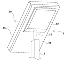
- FIG. 1 It is the external appearance perspective view which looked at the solar cell power supply device from the front side. It is a disassembled sectional view of the solar cell panel of FIG. 3 is a cross-sectional view taken along line III-III of the solar cell panel of FIG. 1.
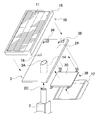
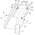
- FIG. 1 It is the perspective view which looked at the solar cell power supply device of FIG. 1 from the back side. It is a perspective view which shows the state which removed the battery cover from the solar cell power supply device of FIG. 4, and exposed the battery box.
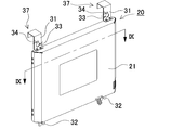
- FIG. 7 is a horizontal sectional view of the battery box of FIG. 6 taken along line IX-IX. It is a disassembled perspective view which shows the state which removed the outer case from the battery box of FIG. It is a disassembled perspective view which shows the state which pulled out the assembled battery from the waterproof bag further from the state of FIG. It is the perspective view which looked at the assembled battery from the front. It is a disassembled perspective view which shows the state which extracted the battery cell from the battery holder about the upper stage of FIG. It is a perspective view which shows the bending of a lead board. It is sectional drawing of the battery box which concerns on a modification. It is a perspective view which shows the solar cell power supply device which concerns on a modification.
- each element constituting the present invention may be configured such that a plurality of elements are constituted by the same member and the plurality of elements are shared by one member, and conversely, the function of one member is constituted by a plurality of members. It can also be realized by sharing.
- the contents described in some examples and embodiments may be used in other examples and embodiments.
- FIG. 1 is an external perspective view of a solar cell power supply device viewed from the front side
- FIG. 2 is an exploded sectional view of the solar cell panel of FIG. 1
- FIG. 3 is a III-III line of the solar cell panel of FIG. 4
- FIG. 5 is a perspective view of the battery box with the battery cover removed from FIG. 4
- FIG. 6 is a battery box.
- 7 is a perspective view seen from diagonally below on the back side
- FIG. 7 is a perspective view seen from diagonally below, FIG.
- FIG. 8 is a perspective view seen from diagonally below on the front side
- FIG. 9 is seen from line IX-IX in FIG. 10
- FIG. 11 is an exploded perspective view with the assembled battery removed from the waterproof bag
- FIG. 12 is a front view of the assembled battery.
- FIG. 13 is a perspective view seen from above, and FIG. An exploded perspective view of the stomach condition, respectively.
- the solar cell power supply device 100 shown in these drawings shows an example applied to a power supply device for a street light. For this reason, the solar cell power supply apparatus 100 is fixed to the upper end of the column.
- the street lamp includes a base portion 3 fixed in an obliquely inclined posture at an upper end of a rectangular column 2 in cross-sectional view, and a cross-sectional view fixed to the base portion 3.
- a rectangular solar cell power supply device 100 and an illuminating means 4 fixed to the support column 2 below the rectangular solar cell power supply device 100 are provided.
- the solar cell power supply apparatus 100 has a solar battery panel 10 exposed on the surface side of a metal rectangular plate-shaped base portion 3, and a battery box 20 containing a battery pack on the back side as shown in FIGS. It is fixed. As shown in FIGS. 2 and 4, the battery box 20 covers the outside with a battery cover 12 to double protect the battery cells 41 from wind and snow.
- This solar cell power supply apparatus 100 irradiates solar cell panel 10 with sunlight in the daytime to generate electric power, charges the assembled battery with the electric power, and drives illumination means 4 with this electric power at night. Thereby, a street lamp can be lit at night without using a commercial power source, and a self-contained street lamp having a power generation function can be obtained. (Solar cell panel 10)
- the solar cell panel 10 is a flat panel (solar panel) in which a plurality of solar cells are arranged on a plane and this surface is exposed as a sunlight receiving surface.
- the installation angle of the solar panel 10 is determined by the angle with the support 2.
- the solar cell panel 10 includes a rectangular plate-shaped panel portion 11 and an outer frame 15 made of an aluminum alloy or the like attached to the outer periphery thereof.
- the panel portion 11 has a structure in which a tempered glass having translucency is used on the light receiving surface side of the front surface, a film is used on the back surface, solar cells are sandwiched therebetween, and an internal gap is filled with a transparent resin.
- the outer frame 15 includes protruding portions 13 having a substantially L shape in cross-section in the four long sides.
- a female screw portion is provided on the surface portion of the protruding portion 13 using a known member. Thereby, the protrusion part 13 is being fixed from the back surface side of the base part 3 using the volt
- the base portion 3 is composed of a substantially rectangular metal plate (material such as iron) 24 and a cylindrical connecting portion 14 fixed to the substantially central portion thereof by welding or the like.
- the width of the flat plate 24 of the base portion 3 is determined so that the solar cell panel 10 can be mounted.
- the upper end of the support column 2 is provided with a cylindrical connecting portion 2 ⁇ / b> C inserted into the connecting portion 14, and the cylindrical connecting portion 2 ⁇ / b> C is inserted into the connecting portion 14. It is fixed by a known means such as screwing from the outside.
- the flat plate 24 is provided with an opening 3 ⁇ / b> A that communicates with the column 2.
- the electrical wiring from the battery box 20 is arranged through the other opening 16 from the back surface side of the flat plate 24 to the front surface side of the flat plate 24, that is, the solar cell panel 10 side, and then through the opening of the flat plate 24. Arranged inside. In the other opening 16, the output line from the solar cell panel 10 is wired to the battery box 20.
- the installation angle of the solar cell panel 10 is generally known as an optimum angle at which the maximum annual power generation amount can be obtained according to the latitude of the place where the solar panel 10 is installed.
- the installation angle is preferably larger than the angle.
- the power generation amount is increased particularly in winter by setting the installation angle larger than the standard installation angle.
- the amount of heat from sunlight obtained by the solar cell panel 10 in the winter can be increased.
- the temperature of the battery cell can be raised by the amount of heat from sunlight, and the generated power can be improved, so that the amount of charge generated due to the low temperature of the battery cell, that is, the decrease in power can be suppressed, and the amount of heat generated in summer can be reduced.
- excellent effects of securing the amount of power generation in winter and suppressing temperature rise in summer can be obtained.
- an amorphous silicon type, a crystalline silicon type, or a hybrid (HIT) type solar cell, a compound type solar cell such as GaAs or CIS type, or an organic type solar cell can be used. Since these solar cells have a small temperature coefficient, there is an advantage that the seasonal variation of the maximum output operating voltage Vop of the solar cell panel 10 is small. Therefore, there is an advantage that the voltage design for charging with high efficiency through the season becomes easy. (Battery box 20)
- the battery box 20 is fixed to the back surface of the solar cell panel 10. As shown in FIGS. 6 to 9 and the like, the battery box 20 has a flat box-like outer shape, and a fixed surface on the side fixed to the solar cell panel 10 is flat. Further, as shown in FIG. 6, the corners on the back side are chamfered to reduce wind resistance.
- the battery box 20 includes a metal outer case 21 having excellent thermal conductivity on the outside.
- fixing brackets 30 are provided as fixing mechanisms for fixing the solar cell panel 10 to the four corners.
- the battery box 20 is fixed substantially parallel to the solar cell panel 10 by a fixing bracket 30. Accordingly, the plate shape can be maintained integrally with the solar cell panel 10 after the battery box 20 is fixed, and the outer shape of the solar cell power supply device 100 can be slimmed.
- the assembled battery housed in the battery box 20 is arranged to be separated from the solar battery panel 10 substantially in parallel.
- the solar battery panel 10 can be heated uniformly by the heat of sunlight, and the battery cell 41 can be heated evenly, and the charging efficiency especially in winter is improved.
- the battery pack 40 by configuring the battery pack 40 so that the upper limit of the chargeable temperature does not exceed the summertime and the lower limit of the battery pack 40 not exceeding the wintertime, an efficient use of the secondary battery can be achieved.
- the battery box 20 is preferably installed above the fixed portion of the support column 2 on the back surface of the solar cell panel 10. Thereby, the wind is less likely to be blocked by the support column 2, and the temperature rise of the battery box 20 can be suppressed particularly in summer, by being directly exposed to the wind. (Battery 40)
- a plurality of chargeable cylindrical battery cells 41 are arranged in the battery box 20. As shown in FIGS. 10 to 13 and the like, these battery cells 41 are connected in series along a cylindrical extending direction to constitute a battery module.
- the assembled battery 40 is configured by arranging a plurality of battery modules in parallel. The battery module is held such that a cylindrical battery cell 41 is placed vertically as shown in FIG. As a result, as will be described later, air in the battery box 20 is circulated by natural convection of heat, so that excessive heating is avoided even in summer and the battery cell 41 can be driven efficiently throughout the year. (Battery cell 41)
- the battery cell 41 uses a columnar or cylindrical battery cell extending in one direction.
- a secondary battery such as a lithium ion secondary battery, a nickel metal hydride battery, or a nickel cadmium battery can be suitably used.
- a lithium ion secondary battery is desirable. Since the lithium ion secondary battery has a high volume density, it can be suppressed to a size and weight that can be installed on the back surface of the solar cell panel 10. In addition, it has a characteristic that an endothermic reaction occurs during charging. In particular, the endothermic effect becomes significant when the charging speed is high.
- the lithium ion secondary battery has a wider chargeable / dischargeable temperature range than lead-acid batteries and nickel metal hydride batteries, and can be charged and discharged efficiently throughout the year.
- the shape of a battery cell it can also be set as the rectangular battery which is a rectangular plate shape with thickness other than column shape or cylindrical shape.
- an iron phosphate-based material for the positive electrode material of the battery cell 41.
- safety can be improved, temperature dependence of charging / discharging can be suppressed, and since relatively high charging / discharging efficiency can be maintained even at low temperatures, charging / discharging can be efficiently performed even in winter.
- the positive electrode of the lithium ion secondary battery can be a three-component positive electrode.
- a mixture of Li—Ni—Mn—Co composite oxide and lithium cobalt oxide is used for the positive electrode instead of the conventional lithium cobalt oxide. Since this lithium ion secondary battery uses Ni—Mn—Co composed of three components in addition to lithium for the positive electrode, it is charged with high voltage and has high thermal stability, and the maximum charging voltage is 4.3V. You can increase the capacity.
- the voltage during charging is a voltage that is intentionally lower than the voltage determined to be fully charged in the battery cell 41 to be used.
- a voltage that is intentionally lower than the voltage determined to be fully charged in the battery cell 41 is used.
- the rated voltage as the nominal voltage of the assembled battery 40 composed of the battery cells 41 (in the case of a lithium ion secondary battery, the voltage value is obtained by multiplying approximately 3.7 to 4.0 V / cell by the number of series).
- the solar cell panel 10 is preferably selected so as to be lower than the maximum output operating voltage Vop. More preferably, it is 70 to 90% of Vop. This is because the operating voltage of the solar battery panel is affected by the voltage of the assembled battery 40, and the charging power is reduced at a voltage away from Vop. Furthermore, the voltage of the solar cell panel 10 is higher than the depth of discharge of the assembled battery 40. Therefore, in order to perform full charge, it is more desirable to approach Vop when it is close to a fully charged state. In addition, it is necessary to select an appropriate assembled battery 40 voltage in consideration of the fluctuation of the voltage of the solar cell panel 10 depending on the temperature. Therefore, it is more desirable that the voltage range is as described above.
- a DC / DC converter is not required when charging the battery cell 41, and power loss in the DC / DC converter can be suppressed. This enables high-efficiency charging, eliminates the need to replace the DC / DC converter, and reduces the number of parts, improving reliability and reducing costs by reducing the failure rate and realizing long-term maintenance-free operation. Is expected.
- the chargeable temperature region and the dischargeable temperature region of the battery cell 41 are set to be different from each other, and the dischargeable region is set to be widened to the low temperature side. As a result, it is possible to discharge efficiently even at night when the temperature is often lower than during daytime charging.
- the assembled battery 40 is further housed in the outer case 21 in a state of being housed in a waterproof bag 22 made of a resin material as shown in FIG.
- the waterproof bag 22 has a box shape with one opening so as to accommodate the assembled battery 40 therein, and is made of a resin material having excellent heat dissipation.
- screwing or the like of screws is used in order to fix the waterproof bag 22 inside the outer case 21, screwing or the like of screws is used.
- a plurality of metal pipes 23 each having a thread groove through which a screw is passed are cut in the vertical direction, and the pipes 23 are fixed to the inside of the outer case 21 with screws.
- the inner surface of the outer case is fixed as a pressed state.
- the pipe 23 is formed to have approximately the same size as the longitudinal length of the inner surface of the outer case 22.
- a V-shaped groove into which the pipe 23 is inserted is formed on the outer surface of the waterproof bag 22.
- the outer case 21 is divided into an upper case 21A and a lower case 21B, and the waterproof bag 22 is accommodated therein, and the battery cell 41 is charged and discharged at the lower part of the waterproof bag 22 as shown in FIGS.
- the charge / discharge control unit 50 to be controlled is housed. (Charge / Discharge Control Unit 50)
- the charging / discharging control unit 50 appropriately controls the charging current and charging voltage for charging / discharging the assembled battery 40 with the electric power generated by the solar cell panel 10.
- the amount of power generated by the solar cell panel 10 varies greatly depending on the weather, season, time, and the like.
- the battery cell 41 is appropriately charged according to such a constantly changing power generation amount.
- the charge / discharge method a known method can be appropriately used. For example, pulse charge can be used to prevent overcharge.
- the charging voltage to the battery cells is set according to the number of battery cells connected in series. At this time, it is preferable to set the voltage lower than the voltage that should be determined to be fully charged due to the characteristics of the battery cell. Thereby, the burden at the time of charge to a battery cell can be reduced, the lifetime of a battery cell can be lengthened, and it can contribute to realization of a maintenance-free power supply device. For example, when a lithium ion secondary battery is used as a battery cell, the battery life can be extended by suppressing the charging voltage to 4.0 V / cell instead of the usual 4.2 V / cell. Can reduce the frequency.
- the PWM method can be used for control during discharge.
- brightness control during lighting and power consumption can be adjusted.
- the PWM method by controlling the illuminance adjustment of the LED by the PWM method, it is possible to easily suppress the illuminance change due to the battery voltage that changes according to the discharge depth of the battery cell by adjusting the PWM duty ratio. Compared to control using a transformer or the like, it is possible to supply power with high efficiency, and to ensure a long illumination ON time.
- the charge / discharge control unit 50 can determine switching between charging and discharging of the battery cell 41 based on the voltage of the solar battery panel 10. That is, when the sun rises and the voltage of the solar battery panel 10 rises, charging of the battery cells 41 starts. Conversely, when the sun goes down and the voltage drops, the charging mode is switched to the discharging mode, and the driving of the lighting unit 4 is started. .
- Each battery cell 41 is housed in a battery holder 42 as shown in FIGS.
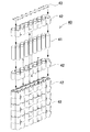
- the battery holder 42 is divided into two parts to completely cover the outside so as to sandwich the cylindrical battery cell 41 from above and below. Further, the end faces of the battery cells 41 are connected to each other by the lead plate 43 at the end face of the battery holder 42.
- the battery holders 42 are fixed by screwing or the like.
- the battery cells 41 to be installed in the battery box 20 are desirably arranged so as to be one row or two rows or less in the thickness direction. By installing in this way, the heat of the back surface of the solar cell panel 10 can be easily propagated throughout the assembled battery 40. Moreover, the heat of the battery cell 41 can also be cooled effectively.
- the battery cells 20 are arranged in an offset shape by arranging two rows of battery cells 41 to reduce the thickness of the battery box 20 to about 1.5 rows.
- FIG. 9 eight battery cells are arranged in two rows in an offset shape, a total of 16 cells are connected in parallel, and four battery holders 42 are connected in series in the vertical direction as shown in FIG. Four cells are connected in series.
- Two battery packs 40 in the state of FIG. 13 are prepared and electrically connected in parallel to form the battery box 20 and battery pack 40 shown in FIGS. With this configuration, the battery cells 41 are electrically connected in 4 series and 32 parallel, and are charged and discharged.
- the number of parallel connections for example, 26 parallel
- the number of serial connections can be appropriately changed by changing the battery holder 42 or the like. In order to connect the battery cells in series, as shown in the cross-sectional view of FIG.
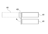
- the upper cell and the lower cell are connected by a lead plate 43, and the lead plate 43 is bent by 180 degrees and connected.
- each battery cell 41 can be in a state facing either the upper or lower surface of the battery box, and the battery cells 41 can be efficiently cooled from each surface.
- the battery cells 41 can be arranged in one row as shown in the modification of FIG. In this modification, the battery cells 41 can be electrically connected in 4 series and 20 parallel by using 10 parallel battery holders 42B and connecting 2 battery packs 40B in parallel. (Battery cover 12)
- covers the exterior with the battery cover 12, as shown in FIG.
- the battery cover 12 is preferably disposed so as to partially cover the support column 2.
- the covering portion of the support column 2 is formed as an inclined surface, it is possible to reduce the resistance of wind blowing from below and contribute to a structure that stably supports the solar cell panel 10.
- the battery cover 12 is made of a metal plate having excellent heat dissipation and durability, such as a sheet metal.
- the metal plate surface can also be used as a heat sink, which is advantageous for air cooling of the assembled battery 40 housed inside.
- the solar cell panel 10 since the solar cell panel 10 is often installed at a high place, the battery cover 12 arranged at a high place with good ventilation can be exposed to the outside air to suppress the temperature rise in summer. Thereby, it can be set as the air-cooled solar cell power supply device using natural wind, and a clean and complete system that does not consume fossil fuel can be realized. (Fixing mechanism)
- the battery box 20 is constituted by a member different from the solar cell panel 10 and includes a fixing mechanism for detachably fixing the back surface of the solar cell panel 10.
- fixing brackets 30 are provided at two places on the left and right sides of the upper and lower ends of the battery box 20 as a fixing mechanism.
- the upper end fixing bracket 31 is a U-shaped piece 37 that is bent at the tip and folded back into a U-shape in cross-section.
- the lower end of the U-shaped piece 37 is fixed to the battery box 20 by being bent in an L shape in cross-section in the opposite direction to the U-shaped.
- a circular hole 33 and a slit 34 extending upward from the round hole 33 and having a width narrower than the diameter of the round hole 33 are opened in the intermediate portion as a locking ring.
- a rectangular U-shaped piece locking port 38 capable of locking the U-shape of the fixing bracket 31 is opened at a position corresponding to the upper end fixing bracket 31 as shown in FIG. ing.
- the fixing screw 36 can be fixed as a locking projection, and the fixing screw 36 inserted from the round hole 33 can be passed through the slit 34, and the screw head of the fixing screw 36 can be screwed and fixed.
- the U-shaped piece 37 is locked to the U-shaped piece locking port 38, and the suspension mechanism in which the locking ring is inserted into the locking projection makes the connecting mechanism extremely simple, In addition, a maintenance-free structure or a highly reliable structure that can withstand long-term use while minimizing malfunctions can be obtained. Furthermore, since it can be temporarily hooked and held at a high place when replacing the battery cell, the battery cell can be prevented from dropping during the fixing operation and workability is improved.
- the lower end fixing bracket 32 has a second slit 35, and a screw inserted in the back surface of the solar cell panel 10 is also passed through the second slit 35, thereby screw head. Screw in and fix.
- this fixing mechanism the battery box 20 can be easily fixed to the back surface of the solar cell panel 10 and can be disassembled. Therefore, operations such as replacement and maintenance of the battery box 20 are facilitated. Particularly in applications where the battery box 20 such as a street light is disposed at a high place, such a simple attachment / detachment mechanism is effective in smoothly performing the installation and replacement work.
- the above-described fixing mechanism is an example, and it goes without saying that other configurations can be used as appropriate.
- a structure in which the battery box 20 is hooked on the back surface of the solar cell panel 10 by a claw-like projection or locking piece, a combination of a hook and a loop, or an L-shaped metal fitting, screwing, etc. can be used as appropriate.
- a suspension-type fixing structure in which the configuration for locking the U-shaped piece to the U-shaped piece locking port is omitted, and the locking ring is simply inserted into the locking projection. It is said. Thereby, the fixing structure can be simplified.
- the strength of the connection can be increased by adding a configuration for locking the U-shaped piece to the U-shaped piece locking port, the heavy battery box 20 is held for a long period of time. From the viewpoint of reliability, it can be said that it is preferable to provide a double fixing structure as shown in FIG.
- the battery box 20 ⁇ / b> B is fixed to an intermediate portion of the support 2. As described above, by fixing the battery box 20B at a position lower than the solar cell panel 10, there is an advantage that the battery can be easily replaced.
- the battery box 20 including the battery cell 41 is unit-type, and can be freely attached to and detached from the solar battery panel so that such replacement work can be performed smoothly. The workability is improved. (Lighting means 4)
- the illumination means 4 shown in FIG. 1 is driven by temporarily charging the assembled battery 40 with the energy generated by the solar cell panel 10 and discharging the assembled battery 40.
- the illuminating means 4 preferably has low power consumption.
- a light emitting diode (LED) is used. LEDs consume less power than fluorescent lamps and can be lit for a long time with less power. Compared to incandescent bulbs, etc., there is almost no fear of bulb breakage, and replacement work is virtually unnecessary, and long-term maintenance-free operation can be realized.
- the LED can be not only constantly lit or continuously lit but also pulsed or flashing. For example, when the remaining capacity of the assembled battery 40 decreases, the lighting time can be increased by switching from the constant lighting to the pulse lighting.
- the ON / OFF cycle of the pulse lighting is preferably set to a high frequency that cannot be recognized by humans, and can be set to, for example, about 10 kHz to 50 Hz. If pulse lighting is used in this way, power consumption can be further reduced, and it can be used to extend the lighting time especially in winter when the sunshine time is short or when cloudy weather such as the rainy season continues. In particular, since the only power that can be stored in the battery cell is sunlight, when there is no sunshine such as rainy weather, avoiding and suppressing the situation where the power stored in the battery cell is insufficient and night lighting is impossible it can.
- This street lamp can be conveniently used as night lighting in an environment where a commercial power source cannot be used or is difficult to use, such as in mountainous areas and uninhabited islands. Moreover, in such an aspect, it is preferable to make it maintenance-free, and it is preferable to use a long-life battery cell or illumination means. For example, by using a lithium ion secondary battery as a battery cell, high power can be charged and discharged with a smaller number of battery cells. Further, by suppressing the current and voltage during charging of the secondary battery to below the rating, it is possible to reduce the load on the secondary battery and extend the life.
- LED light emitting diode
- a conventional solar cell power supply device disclosed in Patent Document 1 is provided with a triangular prism-shaped storage body 512 on the back surface of a solar cell panel 510 as in the solar battery power supply device 500 shown in FIG. By attaching the column 502 to the bottom surface of 512, the solar cell panel 510 was fixed in an inclined posture, and a storage battery was disposed inside the housing 512.
- the storage body 512 since the storage body 512 has a shape protruding from the back surface of the solar cell panel 510, there is a problem that the size is increased.
- solar cell panels are often installed at high positions so that sunlight can be received efficiently, but they are easily affected by wind at high positions. If there is a projecting portion, it is easy to bend by receiving wind resistance, and it is necessary to configure it with sufficient strength, which increases the cost.
- the outer shape can be maintained in a flat shape, and the protrusions are reduced to reduce the wind.
- the resistance can be reduced and the design can be well organized.
- the battery box may be fixed at a middle or lower position instead of on the support column.
- the battery box is easily flooded in the event of a disaster such as a flood or a tsunami, so that the function as an emergency light is hindered.
- charging of the battery cell may be hindered by an overcooled state.
- such a risk is reduced by arrange
- the weight of the assembled battery can be relatively reduced by using a lithium ion secondary battery having a high voltage per volume as an assembled battery as compared with a nickel cadmium battery conventionally used.
- a light-emitting diode with low power consumption is used in place of a conventional incandescent bulb or fluorescent lamp as the illumination means, the voltage can be further reduced, so that the number of required assembled batteries can be further reduced and the weight can be reduced.
- a panel-like solar battery power supply device in which a suitable solar battery and storage battery meeting the above specifications are integrated can be obtained.
- the battery cells arranged in the battery box can be heated by the heat from the solar battery panel, which is heated by sunlight, and the charging efficiency in winter can be improved. . That is, the charging efficiency is generally lowered when the temperature of the battery cell is lowered.
- the battery cell becomes a shaded surface for the convenience of arranging the solar battery panel basically on the side where the sunlight hits, and the temperature tends to decrease. It is in. For this reason, especially in winter, the amount of power that can be charged (the amount of stored electricity) tends to decrease due to the short sunshine hours and the small amount of power generated by the solar cell panel itself.
- the battery box is fixed in parallel to the back surface of the solar cell panel so that the assembled battery built in the battery box is brought close to the solar cell panel, and the heat of the solar cell panel is increased.
- a configuration in which the battery cell is heated by use is adopted.
- the battery cell can be heated by the radiant heat using the heat of the solar battery panel without consuming extra power such as a heater, the charging efficiency of the battery cell is improved, and effective use of waste heat is achieved.
- the heat of the solar battery panel is conducted to the battery cell to lower the temperature, and the deterioration of the solar battery panel itself due to heat can also be reduced.
- the assembled battery is separated from the solar battery panel without directly contacting it.
- the assembled battery 40 is accommodated in the battery holder 42 and is further brought into contact with the solar cell panel 10 via the waterproof bag 22 and the outer case 21, thereby avoiding direct thermal coupling and being excessive by the solar cell panel 10.
- the higher the temperature of the battery cell the higher the charging efficiency.
- the temperature is too high, there is an adverse effect such as deterioration of the characteristics of the battery cell. In particular, in the summer, the inside of the battery box may become hot and become overheated. In order to prevent this, the heat insulating effect can be exhibited by interposing a heat insulating member between the assembled battery and the solar battery panel.
- heat convection is generated inside the battery box, the heated air flows upward from the air passage, and the air cooled so as to descend from the periphery of the assembled battery 40 can be formed. An effect of suppressing excessive overheating is obtained.
- the battery box made of metal having excellent thermal conductivity an effect of dissipating heat to the outside due to the heat dissipation of the battery box itself can be obtained.
- the battery box is placed at a high position by the support, it is easy to receive wind, and this can also be expected to have a heat dissipation and cooling effect.
- the overheating reduction effect can be obtained by arranging the battery box on the shade side.
- a configuration in which a temperature difference is intentionally generated in the upper and lower battery cells of the assembled battery can be employed.
- the separation distance so that the lower battery cell is closer to the solar battery panel, and the upper battery cell is farther away from the solar battery panel
- the temperature of the battery cell is high, and a temperature difference is intentionally generated in the vertical direction so that the temperature is low in the upper battery cell, thereby promoting natural convection of the air inside the battery box.
- the gap between adjacent battery cells arranged in parallel can be widened in the upper battery cell and narrowed in the lower battery cell, thereby producing a temperature difference between the upper and lower battery cells as described above. Can be expected.
- the assembled battery may be spatially separated from the solar cell panel, and a further heat insulating effect can be achieved by interposing an air layer.
- the thickness of the battery box is formed larger than the thickness of the assembled battery, the battery cell is fixed to the back side of the battery box, and the surface facing the cell fixing surface is fixed to the back surface of the solar battery panel.
- a space can be easily formed between the assembled battery and the solar cell panel in a state where the battery box is fixed to the solar cell panel.
- the cross-sectional area of the air passage that cools the battery cells by the natural convection of the air inside the battery box can be expanded.
- the size of the solar battery panel 10 and the size of the battery pack 20 or the battery box 20 containing the battery pack 40 do not have to be completely matched.
- the number of battery cells 41 constituting the assembled battery 40 is determined by the required battery capacity, voltage, etc. according to the connected load and specifications. Even if the number of battery cells is not enough to completely fill the back surface of the solar battery panel, the battery assembly heating effect by the solar battery panel described above can be obtained by arranging the battery pack on the back surface of the solar battery panel.
- both may be arranged in parallel, and the distance between the solar cell panel and the assembled battery is maintained substantially constant. In this way, even when the areas are different, this means a state in which the distance between the two is kept constant.
- the installation area of the solar cell is large, or when the installation amount of the battery cell is larger than the installation area, the influence of the wind pressure received by the solar cell part by the wind becomes large.
- FIG. 19 shows an example of a solar battery power supply apparatus 300 in which two battery boxes are arranged vertically on the battery cover 12 and two battery covers 312 are placed horizontally. In this example, two battery covers 312 are arranged side by side horizontally with the support column 2 as the center.
- the present invention is not limited to this example, and can be used for other purposes as a power supply device using solar energy.
- a solar battery panel 410 is arranged on the roof of a bicycle parking lot like the solar battery power supply device 400 shown in FIG. 20, and the battery charger for assist bicycles can be suitably applied.
- the load that is, the assist bicycle battery is set, so that it can be used not only at night but also during the day, and control is performed to charge the battery.
- the assist bicycle battery is not set during the day, the battery pack is charged and stored to prepare for charging at night or when the illuminance is low during the day.
- a stand-alone power supply that can be used without being connected to a commercial power supply can be realized.
- the power can be used even when a commercial power source cannot be used during a disaster, it can be suitably used as an emergency power supply device, for example, an emergency light or an emergency power supply device.
- an emergency power supply device for example, an emergency light or an emergency power supply device.
- it since it does not consume fossil fuel, it is preferable as a clean and ecological power source.
- the solar battery power supply device can be used as appropriate for a stand-alone lighting device that does not require a commercial power supply, a battery charger for an assist bicycle, or the like.
- U-shaped piece 38 ... U-shaped piece locking port 40, 40B ... Battery assembly 41 ... Battery cell 42 42B ... Battery holder 43 ... Lead plate 50 ... Charge / discharge control unit 500 ... Solar cell power supply device 502 ... Pilla 510 ... Solar cell panel 512 ... Housing body
Landscapes
- Engineering & Computer Science (AREA)
- Manufacturing & Machinery (AREA)
- Chemical & Material Sciences (AREA)
- Chemical Kinetics & Catalysis (AREA)
- Electrochemistry (AREA)
- General Chemical & Material Sciences (AREA)
- Life Sciences & Earth Sciences (AREA)
- Sustainable Development (AREA)
- Sustainable Energy (AREA)
- Photovoltaic Devices (AREA)
- Charge And Discharge Circuits For Batteries Or The Like (AREA)
- Secondary Cells (AREA)
Abstract
【課題】冬場においても効率よく充電を行うことのできる太陽電池電源装置を提供する。 【解決手段】複数の充電可能な円筒形の電池セル41を、該円筒形の延長方向に直列に接続した電池モジュールを、複数本平行に配置した組電池40と、組電池40を収納する平板状の電池ボックス20と、組電池40を充電する電力を発生可能な、複数の太陽電池セルを備える太陽電池パネル10とを備え、太陽電池パネル10の背面に、電池ボックス20が配置されると共に、太陽電池パネル10と組電池40との距離が略一定となるように、両者が略平行に配置され、かつ組電池の電池モジュールを非水平姿勢に保持する。
Description
本発明は、太陽光で発電した電力を二次電池に貯えて利用可能とした太陽電池電源装置に関し、特に日中に太陽電池の出力にて二次電池を充電し、夜間に二次電池の出力を用いて電気照明等に利用するための太陽電池電源装置に関する。
CO2削減等の環境問題に配慮し、化石燃料によらない自然エネルギーを用いて発電した電力を蓄電して利用する照明装置が提案されている。特に、太陽電池で昼間発電した電力を蓄電池に蓄電しておき、蓄電した電力で夜間に照明を点灯する独立型の照明装置が山間部等で用いられている(例えば特許文献1参照)。図21に、特許文献1の照明装置の側面図を示す。
照明装置を街路照明などに使用する場合は、直立させた高いポールの上端に固定した形態で利用することが多い。このような形態では、太陽光を受光し易くできる反面、風の影響を受けやすいという問題があった。特に太陽電池パネルは平板状であるため、風の抵抗を受けやすい形状となる上、これに蓄電池を追加するとさらに風の抵抗を受けやすくなってしまい、特に強風を受けると風によって煽られる虞があった。
しかしながら、蓄電池に蓄電できる電力は太陽光のみであるため、必要な電力の確保が重要となる。十分な電力が日中に確保できないと、蓄電池に蓄電した電力が不足し、夜間に照明が消灯することもある。特に、冬場においては日照度が低く、また日照時間も短いために、充分な蓄電量が確保し難い状況となる。
また、充電池の充電特性として、低温時には充電効率が低くなるという問題がある。特に冬場は昼間の時間が短く、夜間の時間が長くなるため、充電効率が低下して日中の充電量が不足する傾向にあり、夜間の常時点灯が難しくなる。このような問題に対して、商用電源でバックアップする方法も提案されているが、自然エネルギーを極力有効に利用したいという要望が高く、また山間部等では、商用電源の確保も容易ではない。
このように、年間を通じて照明の点灯時間を規定時間以上確保することを考慮すると、特に冬場における充電効率の低下を抑制することが必要なる。
本発明は、従来のこのような問題に鑑みてなされたものである。本発明の主な目的は、風の影響を低減できる形態とした太陽電池電源装置を提供することにある。
また本発明の他の目的は、冬場においても効率よく充電を行うことのできる太陽電池電源装置を提供することにある
上記目的を達成するために、本発明の第1の太陽電池電源装置によれば、複数の充電可能な電池セルを、その延長方向に直列に接続した電池モジュールを、複数本平行に配置した組電池と、前記組電池を収納する平板状の電池ボックスと、前記組電池を充電する電力を発生可能な、複数の太陽電池セルを備える太陽電池パネルと、を備え、前記太陽電池パネルの背面に、前記電池ボックスが配置されると共に、前記太陽電池パネルと前記組電池との距離が略一定となるように、両者が略平行に配置され、かつ、前記組電池の電池モジュールを非水平姿勢に保持することができる。これにより、太陽電池パネルを発電手段とし、組電池を蓄電手段とした、外部電源が不要な電源装置を実現すると共に、太陽電池パネルと電池ボックスとを平行に並べることで、板状にスリム化した太陽電池電源装置を得ることができる。よって、風の影響を低減することができると共に、デザイン的にもシンプルな形状となる。
また組電池を太陽電池パネルと配置することで、太陽電池パネルの熱によって均等に加熱されて特に冬場での充電効率を改善すると共に、縦置き姿勢に円筒形の電池モジュールを配置することで、熱の自然対流によって電池ボックス内の空気が循環され、夏場においても過度の加熱が回避され、一年を通じて電池セルを効率よく駆動できる利点が得られる。
また、蓄電池を空冷可能な位置、つまり太陽電池パネルの背面で日陰になっており、風があたりやすい位置に配置することで、夏場においても蓄電池温度が熱くなりすぎることを防ぐことができる。
また第2の太陽電池電源装置によれば、さらに、前記太陽電池パネルを傾斜姿勢で固定するための支柱を備えており、前記電池ボックスが、前記太陽電池パネルの背面において、前記支柱を固定した位置よりも上方に固定することができる。これにより、太陽電池電源装置が風に晒される際、電池ボックスが支柱の影になることを回避し、直接風に晒されるようにして、特に夏場における電池ボックスの温度上昇を抑制できる。
さらに第3の太陽電池電源装置によれば、前記電池ボックス内に配置された組電池を、厚さ方向に2列以下で配置することができる。これにより、電池ボックスの厚さを薄くして太陽電池電源装置の外形のスリム化に寄与すると共に、組電池と太陽電池パネルとの位置による距離差を少なくし、組電池を均一に太陽電池パネルで加熱できる利点が得られる。さらに電池セルからの放熱も、良好にかつ効果的に行うことができる。
さらにまた第4の太陽電池電源装置によれば、さらに前記太陽電池パネルを上面に固定し、前記電池ボックスを下面に固定するためのベース部を備えることができる。これにより、ベース部で太陽電池パネルを背面から支持しつつ、電池ボックスをベース部に固定することができ、これら設置や接続構造をベース部に担わせて簡素化を図ることができる。
さらにまた第5の太陽電池電源装置によれば、前記電池ボックスを、前記ベース部の背面に着脱自在に取り付けるための固定機構を設けることができる。これにより、例えば街路灯のような高所に配置される電池ボックスの装着、交換やメンテナンス作業を容易にできる利点が得られる。
さらにまた第6の太陽電池電源装置によれば、前記固定機構が、前記電池ボックスの上面に固定された断面視コ字状のコ字状片と、該コ字状片を係止可能な大きさに前記ベース部の裏面に開口されたコ字状片係止口とで構成され、前記固定機構によって前記電池ボックスは前記ベース部に着脱式に固定することができる。これにより、コ字状片をコ字状片係止口に係止して電池ボックスを容易にベース部に着脱できる。
さらにまた第7の太陽電池電源装置によれば、前記固定機構が、係止突起に係止環を挿入する懸吊式であり、前記電池ボックスの四隅近傍に固定された固定機構によって着脱式に前記ベース部に固定することができる。これにより、簡単な機構によって電池ボックスを太陽電池パネルの背面に着脱でき、設置時のみならず、取替え等のメンテナンス時にも有利となり、作業者の安全性向上に貢献できる。
さらにまた第8の太陽電池電源装置によれば、さらに前記電池ボックスを前記太陽電池パネルの背面に固定した状態で、該電池ボックスを被覆する電池カバーを備えることができる。これにより電池ボックスを電池カバーで被覆して、風雨雪等から電池セルを二重に保護することができる。
さらにまた第9の太陽電池電源装置によれば、前記電池ボックスを、熱伝導性に優れた金属製で構成することができる。これにより、電池ボックスの表面を放熱板として利用でき、組電池の空冷に有利となる。特に太陽電池パネルは高所に設置されることが多いため、風通しのよい高所に配置された電池ボックスを外気に晒して、夏場の温度上昇を抑制できる。
さらにまた第10の太陽電池電源装置によれば、前記太陽電池パネルの設置角度を、太陽電池電源装置の設置場所における年間発電量が最大となる設置角度よりも大きい角度に設定することができる。これにより、特に冬場においては太陽光が夏場よりも直角に近づく角度に照射されるため、電池セルを温めることができ、特に充電効率の低下する冬場においても、高い充電効率を得ることができる。
さらにまた第11の太陽電池電源装置によれば、さらに、前記太陽電池パネルで発電された電力で前記組電池を充電する充電電流又は充電電圧を制御するための充放電制御部を備えることができる。これにより、太陽電池パネルによって発電された、発電量の変化する電力を安定して組電池に供給して、安全に充電することが可能となる。
さらにまた第12の太陽電池電源装置によれば、さらに、前記組電池で駆動される照明手段を備えることができる。これによって、発電機能を備えた自立式の照明装置を得ることができる。
さらにまた第13の太陽電池電源装置によれば、前記照明手段を発光ダイオードで構成できる。これにより、低消費電力の照明として、夜間の照明時間の長時間化に有利となる。
さらにまた第14の太陽電池電源装置によれば、照明手段を街路灯とできる。これにより、日中に太陽光で発電して蓄電し、夜間にこの電力を利用して照明するクリーンな街路灯が実現できる。
さらにまた第15の太陽電池電源装置によれば、前記電池セルへの充電電圧を、該電池セルの特性上満充電と判定されるべき電圧よりも低い電圧に設定できる。これにより、電池セルへの充電時の負担を低減して、長寿命化を図ることができ、メンテナンスフリーの電源装置が実現される。
さらにまた第16の太陽電池電源装置によれば、前記電池セルがリチウムイオン二次電池とできる。これにより、容積密度を高め、組電池のサイズや重量を抑制して、特に高所設置型の電源装置において有利となる。加えて、充電時が吸熱反応となるため、電池セルの過熱を回避できる。
さらにまた第17の太陽電池電源装置によれば、前記組電池の定格電圧を、前記太陽電池パネルの25℃における最大出力動作電圧の0.7~0.9倍とできる。これにより、組電池の電圧に太陽電池パネルの動作電圧が影響を受ける事態を考慮して、適切な太陽電池パネルの動作電圧を選択できる。
さらにまた第18の太陽電池電源装置によれば、前記電池セルの充電可能温度領域を、放電可能温度領域と異なるように設定し、該放電可能領域は該充電可能領域よりも低温側に拡大できる。これにより、昼間の充電時に比べて低い温度になることが多い夜間においても効率よく放電することが可能になる。
さらにまた第19の太陽電池電源装置によれば、前記電池セルの外形を円筒形とすることができる。
以下、本発明の実施の形態を図面に基づいて説明する。ただし、以下に示す実施の形態は、本発明の技術思想を具体化するための太陽電池電源装置を例示するものであって、本発明は太陽電池電源装置を以下のものに特定しない。なお、特許請求の範囲に示される部材を、実施の形態の部材に特定するものでは決してない。特に実施の形態に記載されている構成部材の寸法、材質、形状、その相対的配置等は特に特定的な記載がない限りは、本発明の範囲をそれのみに限定する趣旨ではなく、単なる説明例にすぎない。なお、各図面が示す部材の大きさや位置関係等は、説明を明確にするため誇張していることがある。さらに以下の説明において、同一の名称、符号については同一もしくは同質の部材を示しており、詳細説明を適宜省略する。さらに、本発明を構成する各要素は、複数の要素を同一の部材で構成して一の部材で複数の要素を兼用する態様としてもよいし、逆に一の部材の機能を複数の部材で分担して実現することもできる。また、一部の実施例、実施形態において説明された内容は、他の実施例、実施形態等に利用可能なものもある。
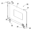
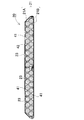
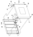
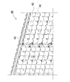
図1~図13に、本発明の一実施の形態に係る太陽電池電源装置100を示す。これらの図において、図1は太陽電池電源装置を正面側から見た外観斜視図、図2は図1の太陽電池パネルの分解断面図、図3は図1の太陽電池パネルのIII-III線における断面図、図4は図1の太陽電池電源装置を背面側から見た斜視図、図5は図4から電池カバーを外して電池ボックスを露出させた状態の斜視図、図6は電池ボックスを背面側の斜め上方から見た外観斜視図、図7は斜め下方から見た斜視図、図8は正面側の斜め下方から見た斜視図、図9は図6のIX-IX線から見た水平断面図、図10は図6から外ケースを外した状態の分解斜視図、図11は図10からさらに防水袋から組電池を抜いた状態の分解斜視図、図12は組電池を正面から見た斜視図、図13は図12の上段について、電池ホルダから電池セルを抜いた状態の分解斜視図を、それぞれ示している。
これらの図に示す太陽電池電源装置100は、街路灯用の電源装置に適用する例を示している。このため太陽電池電源装置100は、支柱の上端に固定されている。この街路灯は、図1及び図2に示すように、断面視矩形状の支柱2の上端に斜めに傾斜視した姿勢で固定されたベース部3と、このベース部3に固定された断面視矩形状の太陽電池電源装置100と、その下方で同じく支柱2に固定された照明手段4とを備えている。太陽電池電源装置100は、金属製の矩形板状のベース部3の表面側に太陽電池パネル10を露出させ、図2及び図5に示すように背面側に組電池を内蔵した電池ボックス20を固定している。また電池ボックス20は、図2及び図4に示すように、電池カバー12で外部を被覆して風雨雪等から電池セル41を二重に保護する。この太陽電池電源装置100は、日中の太陽光を太陽電池パネル10に照射させて発電させ、その電力を組電池に充電しておき、夜間にこの電力で照明手段4を駆動する。これにより、商用電源を用いることなく夜間に街路灯を点灯でき、発電機能を備える自己完結式の街路灯を得ることができる。
(太陽電池パネル10)
(太陽電池パネル10)
太陽電池パネル10は、複数の太陽電池セルを平面上に多数配置し、この面を太陽光の受光面として表出させた平板状のパネル(ソーラーパネル)である。太陽電池パネル10の設置角度は、支柱2との角度によって決定される。
太陽電池パネル10は、矩形板状のパネル部11と、その外周に取付けられたアルミニウム合金等からなる外枠15とを備えている。パネル部11は、その表面の受光面側に透光性を有する強化ガラス、裏面にフィルムを用いて、太陽電池セルをその間に挟み、内部の隙間に透明樹脂を充填した構造である。また、外枠15は、図3の断面図に示すように、長辺の4辺において、断面視略Lの字形状の突出部13を備えている。突出部13をベース部3に固定するために、突出部13の面部分に、周知の部材を利用して雌ネジ部を設ける。これにより、ベース部3の裏面側より、ボルトを用いて、突出部13を固定している。
一方、ベース部3は、概略矩形状の金属製(鉄等の材質)の平板24と、これのほぼ中心部に溶接等により固定された円筒状の連結部14とからなる。ベース部3の平板24は、図3の断面図に示すように、太陽電池パネル10を搭載できるように、平板24の幅が決定される。また図2の分解斜視図に示すように、支柱2の上端には、連結部14の内部に挿入される円筒状連結部2Cを備え、この円筒状連結部2Cを連結部14に挿入して、外部からネジ止め等の周知の手段で固定される。
平板24には開口3Aが設けられており、ここが支柱2と連通している。電池ボックス20からの電気配線は、平板24の裏面側から、平板24の表面側すなわち太陽電池パネル10側に、他の開口16を通じて配設された後、上記平板24の開口を通じて、支柱2の中に配設される。他の開口16においては、太陽電池パネル10からの出力線が、電池ボックス20に配線される。
太陽電池パネル10の設置角度は、一般に設置される場所の緯度に応じて年間の最大発電量が得られる最適な角度が知られているが、本実施の形態においては、このような既知の最適角度よりも大きい設置角度とすることが好ましい。季節毎の太陽高度を想定する場合、冬場は設置角度が大きいことが望ましく、夏場は設置角度が小さいことが望ましい。本実施の形態では、設置角度を標準的な設置角度よりも大きくすることで、特に冬場の発電量を高めている。このような設置角度を採用することで、夏場の発電量は低下するものの、夏場においては日射時間が十分に確保されているため、夜間の照度や点灯時間等において問題が生じることは殆ど無い。逆に、冬場に適した設置とすることで、冬場に太陽電池パネル10で得られる太陽光からの熱量を大きくすることができる。太陽光からの熱量により電池セルの温度が上昇させることができ、発電電力を向上できるので、電池セルが低温であることに起因する充電量すなわち電力の低下を抑制できると共に、夏場に生じる熱量を抑制できるため、結果として冬場の発電量確保と夏場の温度上昇抑制という優れた効果が得られる。
太陽電池セルには、アモルファスシリコン系や結晶シリコン系、或いはこれらのハイブリッド(HIT)型の太陽電池セルや、GaAs、CIS系等の化合物系太陽電池、有機系太陽電池を用いることができる。これらの太陽電池は温度係数が少ないため、太陽電池パネル10の最大出力動作電圧Vopの季節変動が小さいという利点が得られる。そのため、季節を通して高効率に充電をするための電圧設計が容易になる利点がある。
(電池ボックス20)
(電池ボックス20)
太陽電池パネル10の背面には、電池ボックス20が固定される。電池ボックス20は、図6~図9等に示すように外形を平板状の箱形とし、太陽電池パネル10と固定する側の固定面を平面状としている。また図6に示すように背面側の角部を面取りして風の抵抗を低減している。この電池ボックス20は、外部を熱伝導性に優れた金属製の外ケース21で構成される。また四隅に太陽電池パネル10と固定するための固定機構として、固定金具30を設けている。この電池ボックス20は、固定金具30によって太陽電池パネル10とほぼ平行に固定される。これによって、電池ボックス20を固定後も太陽電池パネル10と一体的に、板状を維持でき、太陽電池電源装置100の外形をスリム化できる。また、電池ボックス20に収納された組電池は、太陽電池パネル10とほぼ平行に離間して配置されることとなる。この結果、太陽電池パネル10を太陽光の熱によって電池セル41を均等に加熱することができ、特に冬場での充電効率が向上する。このように、組電池40の充電可能温度の上限を夏場に超えないように、また下限を冬場に超えないように構成することで、効率のよい二次電池の活用を図ることができる。
なお電池ボックス20は、図5に示すように、太陽電池パネル10の背面において、支柱2の固定部分よりも上方に設置することが好ましい。これにより、風が支柱2で遮られることが少なくなり、風に直接晒されるようにして、特に夏場における電池ボックス20の温度上昇を抑制できる。
(組電池40)
(組電池40)
電池ボックス20内には、複数の充電可能な円筒形の電池セル41が配置される。これらの電池セル41は、図10~図13等に示すように、円筒形の延長方向に沿って直列に接続されて電池モジュールを構成する。組電池40は、複数の電池モジュールを複数本平行に配置して構成される。電池モジュールは、水平でない姿勢となるように、すなわち図13に示すように円筒形の電池セル41が縦置きとなるように保持される。これによって後述するように熱の自然対流によって電池ボックス20内の空気が循環され、夏場においても過度の加熱が回避され、一年を通じて電池セル41を効率よく駆動できる利点が得られる。
(電池セル41)
(電池セル41)
電池セル41は、一方向に延在された円柱状又は円筒状の電池セルを使用している。この電池26は、リチウムイオン二次電池やニッケル水素電池、ニッケルカドミウム電池等の二次電池が好適に使用できる。特にリチウムイオン二次電池とすることが望ましい。リチウムイオン二次電池は容積密度が高いために、太陽電池パネル10の背面に設置することが可能なサイズや重量に抑えることができる。加えて、充電時が吸熱反応となる特性を有する。特に充電速度が速いときに吸熱作用が顕著になる。この結果、充電速度が速い夏場において、電池温度が高くなりすぎることを抑制できると共に、充電速度が遅い冬場においては電池温度の低下を抑制することができる。さらに、リチウムイオン二次電池は充放電可能な温度領域が鉛蓄電池やニッケル水素電池に比べて広く、1年を通じて効率よく充放電が可能になる。また、電池セルの形状については、円柱状又は円筒状以外に、厚みのある矩形の板状である角型電池とすることもできる。
また電池セル41の正極材料にはリン酸鉄系材料を用いることが好ましい。これにより、安全性を高めることができ、充放電の温度依存性を抑制することができ、特に低温時にも比較的高い充放電効率を維持できるので、冬場でも効率よく充放電が可能になる。
さらにリチウムイオン二次電池の正極は、3成分正極とすることができる。このリチウムイオン二次電池は、正極に、従来のコバルト酸リチウムに代わって、Li-Ni-Mn-Co複合酸化物とコバルト酸リチウム混合を利用する。このリチウムイオン二次電池は、正極にリチウムに加えて、3成分からなるNi-Mn-Coを使用することから、高電圧で充電して熱安定性が高く、充電最大電圧を4.3Vと高くして容量を大きくできる。
ただし、充電時の電圧は、使用する電池セル41において、満充電と判断される電圧よりも意図的に低い電圧に設定することが好ましい。例えば、リチウムイオン二次電池を使用する場合、一般的な条件下では4.2V付近で満充電と判断されるが、4Vで満充電と判定するよう設定する。これにより、電池セル41の長寿命化が図れる。
さらにまた、電池セル41からなる組電池40の公称電圧としての定格電圧(リチウムイオン二次電池であれば、約3.7~4.0V/セルを直列数で掛けた電圧値となる)を、太陽電池パネル10の最大出力動作電圧Vopよりも低くなるように選択することが好ましい。より望ましくは、Vopの70~90%とする。これは、組電池40の電圧に太陽電池パネルの動作電圧が影響を受けるため、Vopから離れた電圧では充電電力が少なくなるためである。さらに、組電池40の放電深度に比べて太陽電池パネル10の電圧は高くなる。そのため、満充電を行うためには満充電状態に近いときにVopに近づくことがより望ましい。また、温度によって太陽電池パネル10の電圧が変動することを考慮し、適切な組電池40電圧を選択する必要がある。そのために、上記の電圧範囲であることがより望ましい。
また、本実施例においては上記の電圧範囲とすることにより、電池セル41の充電に際してDC/DCコンバータを不要とでき、DC/DCコンバータ内での電力ロスを抑制できる。これによって高効率充電が可能になると共に、DC/DCコンバータの交換作業を無くすと共に部品点数を減らすことができるので、故障率低減による信頼性の向上や低コスト化、長期に渡るメンテナンスフリーの実現が見込まれる。
また、電池セル41の充電可能温度領域と放電可能温度領域とを異ならせるように設定し、放電可能領域を低温側に広くするように設定する。これにより、昼間の充電時に比べて低い温度になることが多い夜間においても効率よく放電することが可能になる。
組電池40は、図11に示すように樹脂材料からなる防水袋22に収納された状態で、さらに外ケース21に収納される。防水袋22は、組電池40を内部に収納するよう一方を開口した箱形としており、放熱性に優れた樹脂材料等で構成される。また防水袋22を外ケース21内部に固定するために、ねじの螺合等が用いられる。図11の例では、ねじを通すねじ溝を内面に切った金属製パイプ23を縦方向に複数配置して、このパイプ23をねじで外ケース21の内部に固定することで、防水袋22を外ケースの内面に押圧状態として固定している。パイプ23は、外ケース22の内面の縦方向長さとほぼ同じ大きさに形成される。また防水袋22の外面には、パイプ23を挿入するV字状の溝が形成されている。さらに外ケース21は、上ケース21A及び下ケース21Bに二分割されて内部に防水袋22を収納すると共に、図10~図11に示すように防水袋22の下部に電池セル41の充放電を制御する充放電制御部50を収納する。
(充放電制御部50)
(充放電制御部50)
充放電制御部50は、太陽電池パネル10で発電された電力で組電池40を充放電する充電電流、充電電圧を適切に制御する。特に太陽電池パネル10の発電量は天候や季節、時間等によって大きく変動する。このような常時変動する発電量に応じて、電池セル41を適切に充電する。
また、充電された電力エネルギーを放電する際の、出力電流、電圧の制御も担う。充放電方式も、既知の方式が適宜利用でき、例えば過充電を防止するためパルス充電とすることができる。さらに電池セルへの充電電圧は、使用する直列接続された電池セル数に応じて設定される。この際、電池セルの特性上満充電と判定されるべき電圧よりも低い電圧に設定することが好ましい。これにより、電池セルへの充電時の負担を低減して、電池セルの寿命を長期化でき、メンテナンスフリーの電源装置実現に貢献できる。例えば、電池セルとしてリチウムイオン二次電池を使用する場合は、充電電圧を通常の4.2V/セルでなく、4.0V/セルに抑えることで長寿命化が図られ、組電池の交換の頻度を少なくできる。
また放電時の制御は、PWM方式が利用できる。これによって、放電時のパルス幅、デューティ比を調整することで、点灯時の明るさ制御と消費電力の調整を行える。特にLEDの照度調整をPWM方式により制御することで、電池セルの放電深度によって変化する電池電圧による照度変化をPWMのデューティ比を調整することにより簡単に抑制できる。またトランス等を利用した制御に比べて、高効率での電力供給が可能になり、長時間の照明ON時間を確保できる。
またこの充放電制御部50は、電池セル41の充電と放電の切り替えを、太陽電池パネル10の電圧によって判定することができる。すなわち、日が昇り太陽電池パネル10の電圧が上昇すると、電池セル41の充電を開始し、逆に日が沈み電圧が低下すると、充電モードから放電モードに切り替え、照明手段4の駆動を開始する。
電池ボックス20内に、充放電制御部50を収納する構成とすることで、電池セル41の温度管理等が容易になるだけでなく、電池セル41の充放電をコントロールするための信号線等が外部に露出することを回避できる。特に主配線となる太陽電池パネル10と電池セル41とを接続する配線距離を最短にできるため、風等による擦れに起因する摩耗や接触不良、断線等の故障を抑制できる。このようにして、耐候性に優れた安定性、信頼性の高い構成が得られる。
(電池ホルダ42)
(電池ホルダ42)
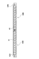
各電池セル41は、図11~図13に示すように電池ホルダ42に収納される。電池ホルダ42は、2分割されて円筒形の電池セル41を上下から挟み込むようにして外部を完全に被覆する。さらに電池ホルダ42の端面で、電池セル41の端面同士をリード板43により接続する。また電池ホルダ42同士は、ねじの螺合等によって固定される。電池ボックス20内に設置する電池セル41は、厚み方向に1列あるいは2列以下となるように配置することが望ましい。このように設置することで、太陽電池パネル10の背面の熱が組電池40の全体に渡って伝搬され易くできる。また、電池セル41の熱も、効果的に冷却することができる。図9の例では、2列の電池セル41をオフセット状に配置することで、電池セル41を約1.5列として電池ボックス20の厚さを薄くしている。
このように、2列の電池セル41をオフセット状に配置することで、1列とする場合や電池セル端面の中心軸を一致させてマトリックス状に2列に積層した場合と比較して、隣接する電池セル41間の間隔を所望の間隔に設定することが可能となり、所望の寸法の電池ボックス20、組電池40とすることができる。
図9の例では、8本の電池セルをオフセット状に2列に並べて、計16セルを並列接続し、さらに図13に示すように上下方向に4つの電池ホルダ42を直列に接続して、4セルの直列接続としている。図13の状態の組電池40を2個用意し、電気的に並列に接続して、図9、図11に示す電池ボックス20、組電池40とする。この構成によって、電池セル41が、4直列32並列に電気接続されて、充電、放電することになる。また、電池ホルダ42を変更する等により、並列する数(例えば、26並列)、直列接続する数を適宜変更することも可能である。なお電池セル同士を直列接続するために、図14の断面図に示すように、上側セルと下側セルをリード板43で接続し、リード板43を180度に折り曲げて、接続する。このように電池セル41を2列以下で配置することで、各電池セル41を電池ボックスの上下面のいずれかに面する状態とし、各面から効率よく電池セル41を冷却できる。もちろん、図15の変形例に示すように、電池セル41を1列で配置することも可能であることはいうまでもない。この変形例では、10並列の電池ホルダ42Bを使用し、組電池40Bを2組並列に接続することで、4直列20並列に電池セル41を電気接続できる。
(電池カバー12)
(電池カバー12)
また電池ボックス20は、図4に示すように電池カバー12で外部を被覆する。電池カバー12で電池ボックス20を被覆することにより、電池ボックス20を風雪雨や鳥等から保護すると共に、デザイン上も太陽電池パネル10との一体感を高めることができる。特に電池カバー12は、支柱2を部分的に被覆するように配置することが好ましい。特に、支柱2の被覆部分を傾斜面とすることで、下方から吹き上げる風の抵抗を低減して、太陽電池パネル10を安定的に支持する構造に寄与できる。この電池カバー12は板金等、放熱性と耐久性に優れた金属板で構成する。この例では、電池ボックス20と電池カバー12を共に金属板とすることで、金属板表面を放熱板としても利用でき、内部に収納する組電池40の空冷に有利となる。特に太陽電池パネル10は高所に設置されることが多いため、風通しのよい高所に配置された電池カバー12を外気に晒して、夏場の温度上昇を抑制できる。これにより、自然の風を利用した空冷式の太陽電池電源装置とでき、化石燃料を消費しないクリーンな完結型のシステムを実現できる。
(固定機構)
(固定機構)
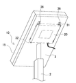
さらにこの電池ボックス20は、太陽電池パネル10と別部材で構成し、太陽電池パネル10の背面で着脱自在に固定するための固定機構を備えている。図5~図8の例では、固定機構として電池ボックス20の上端及び下端でそれぞれ左右2箇所に固定金具30を設けている。上端の固定金具31は、図6に示すように先端部分を折曲し、断面視コ字状に折り返したコ字状片37としている。また下端はこのコ字状片37の該コ字状と逆方向に、断面視L字状に折曲して、電池ボックス20と固定している。さらに中間部分には、係止環として、丸穴33と、丸穴33から上方に延びた、丸穴33の直径よりも幅を狭くしたスリット34を開口している。
一方ベース部3の背面では、図5に示すように上端固定金具31と対応する位置に、固定金具31のコ字状を係止可能な矩形状のコ字状片係止口38を開口している。さらに係止突起として固定ねじ36を固定し、丸穴33から挿入した固定ねじ36をスリット34に通して、固定ねじ36のねじ頭を螺合して固定できる。このようにコ字状片37をコ字状片係止口38に係止すると共に、係止突起に係止環を挿入する懸吊式とすることで、連結機構を極めて簡素化して、故障や不具合を極減して長期使用に耐え得るメンテナンスフリー構造又は信頼性の高い構造とすることができる。さらに電池セルを取り替える際の高所作業に際して、懸吊式として一時的に引っ掛けて保持できるため、固定作業中に電池セルの落下等を阻止でき、作業性も向上する。
また下端の固定金具32は、図7~図8に示すように第二スリット35を開口しており、同じく太陽電池パネル10の背面に挿入されたねじを第二スリット35に通して、ねじ頭を螺合して固定する。この固定機構によれば、簡単に電池ボックス20を太陽電池パネル10の背面に固定し、また分解することができるので、電池ボックス20の交換やメンテナンス等の作業が容易となる。特に街路灯のような電池ボックス20が高所に配置される用途においては、このような簡易な着脱機構は装着、交換作業をスムーズに行う上で有効となる。
なお上記の固定機構は一例であって、他の構成も適宜利用できることはいうまでもない。例えば電池ボックス20を太陽電池パネル10の背面にツメ状等の突起や係止片によって引っ掛ける構造や、同様にフックとループの組み合わせ、あるいはL字金具、ねじ止め等、既知の脱着可能な固定機構が適宜利用できる。例えば図16に示す変形例では、コ字状片をコ字状片係止口に係止する構成を省略して、単に係止突起に係止環を挿入するのみの懸吊式の固定構造としている。これにより固定構造を簡素化できる。ただ、コ字状片をコ字状片係止口に係止する構成を付加することでより連結の強度を増すことができるので、特に重量のある電池ボックス20を長期に渡って保持するという信頼性の面からは、図5で示したような二重の固定構造を備えることが好ましいといえる。
さらに上述の例では、電池ボックスを平板状としてベース部の背面に固定する構造を説明したが、電池ボックスをベース部と離間させて配置する構成としてもよい。図17に示す参考例に係る太陽電池電源装置では、支柱2の中間部分に電池ボックス20Bを固定している。このように太陽電池パネル10よりも低い位置に電池ボックス20Bを固定することで、電池の交換作業を容易に行える利点が得られる。
従来の太陽電池電源装置では、太陽電池パネルの筐体内に蓄電池を配置した構成のため、蓄電池の交換作業が容易でなかった。蓄電池は寿命があり、特に従来のニッケルカドミウム電池の寿命は比較的短く、交換作業が必要となるが、その作業に要する手間や費用が負担となっていた。これに対して本実施の形態では、電池セル41を内蔵した電池ボックス20をユニット式として、太陽電池パネルに着脱自在とすることで、このような交換作業をスムーズに行えるようにして、メンテナンス時の作業性を高めている。
(照明手段4)
(照明手段4)
図1に示す照明手段4は、太陽電池パネル10で発電されたエネルギーを一旦組電池40に充電して、この組電池40を放電することで駆動される。この照明手段4は低消費電力であることが好ましく、例えば発光ダイオード(LED)を利用する。LEDは蛍光灯等に比べ消費電力が低く、少ない電力でも長時間に渡って点灯できる。また白熱電球等と比べ球切れの心配が殆ど無く交換作業を実質的に不要とでき、長期に渡るメンテナンスフリーを実現できる。さらにLEDは常時点灯又は連続点灯するのみならず、パルス点灯又は点滅とすることもできる。例えば、組電池40の残存容量が少なくなると、常時点灯からパルス点灯に切り替えて、点灯時間を長くすることができる。パルス点灯のON/OFF周期は、人間が認識できない程度の高周波数に設定することが好ましく、例えば10kHz~50Hz程度とできる。このようにパルス点灯を利用すれば、さらに消費電力を抑えることができ、特に日照時間の短い冬場や、雨期等曇天が続く場合に、点灯時間を延ばすために利用できる。特に、電池セルに蓄電できる電力は太陽光のみであるため、雨天等の無日照が続いた場合に、電池セルに蓄電した電力が不足して夜間の照明が不可能となる事態を回避、抑制できる。
この街路灯は、山間部や無人島等、商用電源を利用できない、あるいは利用し難い環境において、夜間の照明として便利に使用できる。またこのような態様では、メンテナンスフリーとすることが好ましく、長寿命の電池セルや照明手段を利用することが好ましい。例えば、電池セルとしてリチウムイオン二次電池を使用することで、より少ない電池セル数で高い電力を充放電できる。また、二次電池の充電時の電流や電圧を定格以下に抑えることで、二次電池への負荷を低減して長寿命化を図ることができる。さらに、照明手段として発光ダイオード(LED)を使用すれば、白熱電球や蛍光灯に比べ低消費電力で、素子の寿命も点灯時間1万時間以上と長く、メンテナンスフリー環境が実現できるので極めて好ましい。
太陽電池パネル10は、太陽光を効率よく受けるために、受光面を斜めに保持する必要がある。このため、地面から垂直に直立される支柱に対して太陽電池パネルを斜めに配置する必要がある。特許文献1に開示される従来の太陽電池電源装置は、図21に示す太陽電池電源装置500のように、太陽電池パネル510の背面に、側面視三角柱状の収納体512を設け、この収納体512の底面に支柱502を取り付けることで、太陽電池パネル510の傾斜姿勢での固定を実現すると共に、収納体512の内部に蓄電池を配置していた。この構造では、太陽電池パネル510の背面から収納体512が突出する形状となるため、大型化するという問題があった。特に太陽電池パネルは、太陽光を効率よく受けられるよう、高い位置に設置することが多いが、高い位置では風の影響を受けやすい。突起部分があると風の抵抗を受けて煽られ易くなり、十分な強度に構成する必要があって、コスト的にも高くなる。
これに対して本実施の形態では、平板状の太陽電池パネル10の背面に、同じく平板状の電池ボックス20を固定することで、外形を平板状に維持でき、突起部分を少なくして風の抵抗を低減し、またデザイン的にも纏まりよく構成できる。
また従来は、電池セルが比較的重く、また定期的に交換の必要が生じることから、支柱の上でなく中間や低い位置に電池ボックスが固定されることもあった。この構成では、洪水や津波等の災害時に電池ボックスが浸水し易くなるため、非常灯としての機能に支障が生じる問題もあった。また積雪時に電池ボックスが埋設されると、過冷状態によって電池セルの充電が阻害されることもあった。これに対して上記実施の形態では、太陽電池パネル10と同じ高さに組電池を配置することで、このようなリスクを低減している。特に、従来利用されていたニッケルカドミウム電池と比べ、体積あたりの電圧の高いリチウムイオン二次電池を組電池として使用することで、相対的に組電池重量の軽量化が図られる。また、照明手段として従来の白熱電球や蛍光灯に代えて低消費電力の発光ダイオードを利用すれば、一層低電圧化が図られるため、必要な組電池の本数をさらに少なくして軽量化が図られ、上記仕様に合致した好適な太陽電池と蓄電池を一体型したパネル状の太陽電池電源装置とすることができる。
さらに、この構成であれば、電池ボックスに配置される電池セルを太陽電池パネル自身が太陽光によって熱せられる太陽電池パネルからの熱によって加熱でき、特に冬場の充電効率を改善できるという利点も得られる。すなわち、電池セルは一般に低温になると充電効率が低下する。また、太陽電池パネルの背面に電池セルを配置する構成では、基本的に太陽光の当たる面側に太陽電池パネルを配置する都合上、電池セルは日陰の面となって、温度が低くなる傾向にある。このため、特に冬場は、日照時間が短く、太陽電池パネルによる発電量そのものが少ないこととも相俟って、充電可能な電力量(蓄電量)が低下する傾向にある。蓄電量が不足すると、夜間の照明時間も短くなり、特に雨天の日が続くと照明できなくなる事態も生じる。このような問題に対し、本実施の形態では太陽電池パネルの背面に電池ボックスを平行に固定することで、電池ボックスに内蔵される組電池を太陽電池パネルに近接させ、太陽電池パネルの熱を利用して電池セルが加熱される構成を採用している。これによって、余分なヒータ等の電力を消費することなく、太陽電池パネルの熱を利用した輻射熱によって電池セルを加熱することができ、該電池セルの充電効率が向上され、効果的な廃熱利用システムを構築できる。特に太陽電池パネルの熱を電池セルに熱伝導して温度を低下させ、太陽電池パネルそのものの熱による劣化も低減できる。
なお、好ましくは組電池を太陽電池パネルと直接接触させず、離間させる。この例では組電池40を電池ホルダ42に収納し、さらに防水袋22、外ケース21を介して太陽電池パネル10と接触させることで、直接的な熱結合を回避し、太陽電池パネル10による過剰な加熱の抑制を図っている。一般に電池セルは温度が高い方が充電効率は高いが、高すぎると電池セルの特性が劣化する等の悪影響が生じる。特に、夏場は電池ボックス内が高温になって過熱状態となる可能性がある。これを阻止するため、組電池を太陽電池パネルと離間させることで、間に断熱部材を介在させることで断熱効果を発揮できる。
加えて、円筒型の電池セル41を縦置き、すなわち二次電池の円筒形を縦置き姿勢とすることで、円筒形の二次電池同士の隙間が上下方向に貫通し、通気路が形成してもよい。これにより、電池ボックス内部で熱の対流を生じさせ、加熱された空気が通気路から上方に流れ込み、かつ上方で冷却された空気が組電池40の周囲から下降するよう空気の循環を形成でき、過剰な過熱を抑制する効果が得られる。さらに加えて、電池ボックスを熱伝導性に優れた金属製とすることで、電池ボックスそのものの放熱性によって外部に熱を発散できる効果も得られる。特に電池ボックスは支柱によって高い位置に置かれるため、風を受け易く、これによっても放熱、冷却効果が期待できる。加えて、上述の通り電池ボックスが日陰側に配置されることでも、過熱低減効果が得られる。
なお、電池ボックス内部の対流を促進するため、組電池の上下の電池セルで、意図的に温度差が生じるような構成を採用することもできる。例えば、縦方向に並べて配置された電池セルの内、下方の電池セルでは太陽電池パネルと近付くように、逆に上方の電池セルでは太陽電池パネルと遠ざけるように離間距離を調整することで、下方の電池セルの温度が高く、上方の電池セルで温度が低くなるように意図的に縦方向に温度差を生じさせて、電池ボックス内部の空気の自然対流を促すことができる。あるいは、平行に並べられた隣接する電池セル同士の隙間を、上方の電池セルでは広くし、下方の電池セルでは狭くすることでも、上記と同様に上下の電池セル間に温度差を生じさせる効果が期待できる。
あるいは、組電池を太陽電池パネルと空間的に離間させる構成としてもよく、空気層を介在させることで、一層断熱効果を図ることができる。例えば、電池ボックスの厚さを、組電池の厚さよりも大きく形成し、さらに電池ボックスの背面側に電池セルを固定し、該セル固定面と対向する面を、太陽電池パネルの背面と固定するパネル固定面とすることで、電池ボックスを太陽電池パネルと固定した状態で、組電池と太陽電池パネルとの間に空間を容易に形成できる。また円筒形電池セル同士の隣接する空間を厚さ方向にも拡大することで、電池ボックス内部で電池セルを空気の自然対流により冷却する通気路の断面積を拡張できる。
なお、太陽電池パネル10の大きさと組電池40又は組電池40を収納した電池ボックス20の大きさとは、完全に一致させる必要はない。組電池40を構成する電池セル41の数は、接続される負荷や仕様に応じて必要とされる電池容量や電圧等によって決定される。電池セルの数が、太陽電池パネルの背面をすべて埋め尽くす数に足りなくとも、太陽電池パネルの背面に組電池を配置することで、上述した太陽電池パネルによる組電池の加熱効果が得られる。なお、組電池又は組電池を収納した電池ボックスの大きさが太陽電池パネルよりも小さい場合でも、両者を平行に配置すればよく、太陽電池パネルと組電池との距離をほぼ一定に維持するとは、このように面積が異なる場合でも、両者の間隔が一定に維持される状態を意味する。
また、太陽電池の設置面積が広い場合や、設置面積に比べて電池セル設置量が多い場合等には、風によって太陽電池部分が受ける風圧の影響が大きくなる。この場合、電池セルは複数個設置し、かつ少なくとも太陽電池の傾斜に対して水平方向には支柱2を挟むように設置することが望ましい。これにより、支柱2に対する風圧によるモーメントを制御することができる。
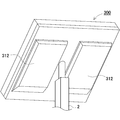
また上記の実施例では、図5に示すように太陽電池パネル10の背面に、1つの電池ボックス20を固定した構成を説明したが、この構成に限らず、例えば図18に示す太陽電池電源装置200のように、2つの電池ボックス20を、支柱2を中心として上下に縦型に配置した構成したり、3以上の電池ボックスを配置したり、あるいは電池ボックスを横置きに配置したりすることもできる。図19に変形例として、電池カバー12に2つの電池ボックスを縦置きに配置し、さらに2つの電池カバー312を横置きにした太陽電池電源装置300の例を示す。この例では、支柱2を中心として左右に水平に、2つの電池カバー312を並べている。
さらに上記の例では、太陽電池電源装置を街路灯に適用した例を説明したが、この例に限られず、太陽エネルギーを利用した電源装置として他の用途にも利用できる。例えば図20に示す太陽電池電源装置400のように駐輪場の屋根に太陽電池パネル410を配置し、アシスト自転車用のバッテリの充電装置にも好適に適用できる。この場合は、夜間に限らず日中でも使用できるよう、負荷すなわちアシスト自転車用バッテリがセットされたことを検出して、その充電を行うように制御する。また日中でアシスト自転車用バッテリがセットされていない場合は、組電池を充電して蓄電しておき、夜間や日中照度の低い場合の充電に備える。
以上のようにして、商用電源に接続することなく利用可能なスタンドアロン式の電源装置が実現できる。特に、災害時のような商用電源が利用できない場合にも電力を利用可能であることから、非常用の電源装置として、例えば非常灯や非常電源装置として好適に利用できる。また、化石燃料を消費しない点から、クリーンでエコロジーな電源としても好ましい。
本発明に係る太陽電池電源装置は、商用電源を必要としないスタンドアロン式の照明装置やアシスト自転車のバッテリの充電装置等に適宜利用できる。
100、200、300、400…太陽電池電源装置
2…支柱
2C…円筒状連結部
3…ベース部
3A…開口
4…照明手段
10、410…太陽電池パネル
11…パネル部
12、312…電池カバー
13…突出部
14…連結部
15…外枠
16…他の開口
20、20B…電池ボックス
21…外ケース
21A…上ケース
21B…下ケース
22…防水袋
23…パイプ
24…平板
30…固定金具
31…上端固定金具
32…下端固定金具
33…丸穴
34…スリット
35…第二スリット
36…固定ねじ
37…コ字状片
38…コ字状片係止口
40、40B…組電池
41…電池セル
42、42B…電池ホルダ
43…リード板
50…充放電制御部
500…太陽電池電源装置
502…支柱
510…太陽電池パネル
512…収納体
2…支柱
2C…円筒状連結部
3…ベース部
3A…開口
4…照明手段
10、410…太陽電池パネル
11…パネル部
12、312…電池カバー
13…突出部
14…連結部
15…外枠
16…他の開口
20、20B…電池ボックス
21…外ケース
21A…上ケース
21B…下ケース
22…防水袋
23…パイプ
24…平板
30…固定金具
31…上端固定金具
32…下端固定金具
33…丸穴
34…スリット
35…第二スリット
36…固定ねじ
37…コ字状片
38…コ字状片係止口
40、40B…組電池
41…電池セル
42、42B…電池ホルダ
43…リード板
50…充放電制御部
500…太陽電池電源装置
502…支柱
510…太陽電池パネル
512…収納体
Claims (19)
- 複数の充電可能な電池セルを、その延長方向に直列に接続した電池モジュールを、複数本平行に配置した組電池と、
前記組電池を収納する平板状の電池ボックスと、
前記組電池を充電する電力を発生可能な、複数の太陽電池セルを備える太陽電池パネルと、
を備え、
前記太陽電池パネルの背面に、前記電池ボックスが配置されると共に、
前記太陽電池パネルと前記組電池との距離が略一定となるように、両者が略平行に配置され、
かつ、前記組電池の電池モジュールが非水平姿勢に保持されてなることを特徴とする太陽電池電源装置。 - 請求項1に記載の太陽電池電源装置であって、さらに、
前記太陽電池パネルを傾斜姿勢で固定するための支柱を備えており、
前記電池ボックスが、前記太陽電池パネルの背面において、前記支柱を固定した位置よりも上方に固定されてなることを特徴とする太陽電池電源装置。 - 請求項1又は2に記載の太陽電池電源装置であって、
前記電池ボックス内に配置された組電池は、厚さ方向に2列以下で配置されてなることを特徴とする太陽電池電源装置。 - 請求項1から3のいずれか一に記載の太陽電池電源装置であって、さらに、
前記太陽電池パネルを上面に固定し、前記電池ボックスを下面に固定するためのベース部を備えることを特徴とする太陽電池電源装置。 - 請求項4に記載の太陽電池電源装置であって、
前記電池ボックスを、前記ベース部の背面に着脱自在に取り付けるための固定機構を設けてなることを特徴とする太陽電池電源装置。 - 請求項5に記載の太陽電池電源装置であって、
前記固定機構が、前記電池ボックスの上面に固定された断面視コ字状のコ字状片と、該コ字状片を係止可能な大きさに前記ベース部の裏面に開口されたコ字状片係止口とで構成され、
前記固定機構によって前記電池ボックスは前記ベース部に着脱式に固定されてなることを特徴とする太陽電池電源装置。 - 請求項5又は6に記載の太陽電池電源装置であって、
前記固定機構が、係止突起に係止環を挿入する懸吊式であり、
前記電池ボックスの四隅近傍に固定された固定機構によって着脱式に前記ベース部に固定されてなることを特徴とする太陽電池電源装置。 - 請求項4から7のいずれか一に記載の太陽電池電源装置であって、さらに、
前記電池ボックスを前記太陽電池パネルの背面に固定した状態で、該電池ボックスを被覆する電池カバーを備えてなることを特徴とする太陽電池電源装置。 - 請求項1から8のいずれか一に記載の太陽電池電源装置であって、
前記電池ボックスが、熱伝導性に優れた金属製で構成されてなることを特徴とする太陽電池電源装置。 - 請求項1から9のいずれか一に記載の太陽電池電源装置であって、
前記太陽電池パネルの設置角度を、太陽電池電源装置の設置場所における年間発電量が最大となる設置角度よりも大きい角度に設定してなることを特徴とする太陽電池電源装置。 - 請求項1から10のいずれか一に記載の太陽電池電源装置であって、さらに、
前記太陽電池パネルで発電された電力で前記組電池を充電する充電電流又は充電電圧を制御するための充放電制御部を備えてなることを特徴とする太陽電池電源装置。 - 請求項1から11のいずれか一に記載の太陽電池電源装置であって、さらに、
前記組電池で駆動される照明手段を備えてなることを特徴とする太陽電池電源装置。 - 請求項12に記載の太陽電池電源装置であって、
前記照明手段が発光ダイオードで構成されてなることを特徴とする太陽電池電源装置。 - 請求項13に記載の太陽電池電源装置であって、
前記照明手段が街路灯であることを特徴とする太陽電池電源装置。 - 請求項1から14のいずれか一に記載の太陽電池電源装置であって、
前記電池セルへの充電電圧を、該電池セルの特性上満充電と判定されるべき電圧よりも低い電圧に設定してなることを特徴とする太陽電池電源装置。 - 請求項1から15のいずれか一に記載の太陽電池電源装置であって、
前記電池セルがリチウムイオン二次電池であることを特徴とする太陽電池電源装置。 - 請求項1から16のいずれか一に記載の太陽電池電源装置であって、
前記組電池の定格電圧が、前記太陽電池パネルの25℃における最大出力動作電圧の0.7~0.9倍であることを特徴とする太陽電池電源装置。 - 請求項1から17のいずれか一に記載の太陽電池電源装置であって、
前記電池セルの充電可能温度領域が、放電可能温度領域と異なるように設定し、該放電可能領域は該充電可能領域よりも低温側に拡大してなることを特徴とする太陽電池電源装置。 - 請求項1から18のいずれか一に記載の太陽電池電源装置であって、
前記電池セルが、外形を円筒形とすることを特徴とする太陽電池電源装置。
Priority Applications (3)
| Application Number | Priority Date | Filing Date | Title |
|---|---|---|---|
| CN2011800069497A CN102725864A (zh) | 2010-01-28 | 2011-01-26 | 太阳能电池电源装置 |
| US13/575,746 US20120300440A1 (en) | 2010-01-28 | 2011-01-26 | Solar battery power supply device |
| EP11737039.5A EP2530735A4 (en) | 2010-01-28 | 2011-01-26 | SOLAR POWER |
Applications Claiming Priority (2)
| Application Number | Priority Date | Filing Date | Title |
|---|---|---|---|
| JP2010017498A JP5241745B2 (ja) | 2010-01-28 | 2010-01-28 | 太陽電池電源装置 |
| JP2010-017498 | 2010-01-28 |
Publications (1)
| Publication Number | Publication Date |
|---|---|
| WO2011093326A1 true WO2011093326A1 (ja) | 2011-08-04 |
Family
ID=44319312
Family Applications (1)
| Application Number | Title | Priority Date | Filing Date |
|---|---|---|---|
| PCT/JP2011/051474 Ceased WO2011093326A1 (ja) | 2010-01-28 | 2011-01-26 | 太陽電池電源装置 |
Country Status (5)
| Country | Link |
|---|---|
| US (1) | US20120300440A1 (ja) |
| EP (1) | EP2530735A4 (ja) |
| JP (2) | JP5241745B2 (ja) |
| CN (1) | CN102725864A (ja) |
| WO (1) | WO2011093326A1 (ja) |
Families Citing this family (28)
| Publication number | Priority date | Publication date | Assignee | Title |
|---|---|---|---|---|
| JP5241745B2 (ja) * | 2010-01-28 | 2013-07-17 | 三洋電機株式会社 | 太陽電池電源装置 |
| JP5842150B2 (ja) * | 2011-08-24 | 2016-01-13 | パナソニックIpマネジメント株式会社 | 太陽光発電装置および照明器具 |
| US9293948B2 (en) * | 2012-09-19 | 2016-03-22 | Sundial Energy, Inc. | Renewable uninterrupted power supply for critical node infrastructure support |
| USD738819S1 (en) * | 2012-11-02 | 2015-09-15 | Chicago Display Company | Battery housing for a solar light fixture |
| JP6185307B2 (ja) * | 2013-07-04 | 2017-08-23 | 積水樹脂株式会社 | 照明灯 |
| JP6174928B2 (ja) * | 2013-07-18 | 2017-08-02 | 積水樹脂株式会社 | 表示装置 |
| FR3015810B1 (fr) * | 2013-12-24 | 2017-04-28 | Sunna Design | Solution de gestion thermique limitant le vieillissement premature d'une batterie alimentee par une source d'energie photovoltaïque pour application autonome. |
| FR3020221B1 (fr) * | 2014-04-22 | 2017-11-24 | Olivier Panya Krug | Module de stockage d'energie electrique pour dispositif de conversion d'energie photovoltaique en energie electrique |
| JP6381985B2 (ja) * | 2014-06-16 | 2018-08-29 | アロイ工業株式会社 | 太陽電池電源装置 |
| WO2017021890A1 (en) * | 2015-08-04 | 2017-02-09 | Goal Zero Llc | Portable solar panel system control |
| NL2015268B1 (en) * | 2015-08-05 | 2017-02-16 | Solartechno Europe B V | Solar power system |
| US10181814B2 (en) * | 2015-09-15 | 2019-01-15 | Wilson Chan | Solar battery system for low temperature operation |
| JP6740769B2 (ja) * | 2016-07-21 | 2020-08-19 | 岩崎電気株式会社 | 支柱支持構造、及び太陽電池装置支柱支持構造 |
| US10483908B2 (en) * | 2017-05-24 | 2019-11-19 | Shenzhen Dansha Technology Co., Ltd. | Wearable power management system |
| CN107339677A (zh) * | 2017-08-01 | 2017-11-10 | 深圳市鹏诚新能源科技有限公司 | 太阳能路灯 |
| CN107623368B (zh) * | 2017-09-27 | 2020-07-31 | 浙江海鸿工业产品设计有限公司 | 一种光伏发电组件 |
| US20200173618A1 (en) * | 2018-11-30 | 2020-06-04 | Evergreen Enterprises Of Virginia, Llc | Decorative solar-powered lighting system, a decorative solar module overlay, and a decorative solar module assembly for a decorative solar-powered lighting system |
| US10903780B2 (en) * | 2019-01-08 | 2021-01-26 | Bill Wilson | Rechargeable battery powered generator |
| IT201900022746A1 (it) * | 2019-12-03 | 2021-06-03 | Hdemia S R L | Dispositivo atto al fissaggio di pannelli fotovoltaici |
| CN113639240B (zh) * | 2021-07-05 | 2023-04-11 | 江苏迪生建设集团有限公司 | 一种高效发电太阳能led路灯 |
| JP7215611B1 (ja) | 2022-02-01 | 2023-01-31 | スズキ株式会社 | 街灯 |
| KR102639987B1 (ko) * | 2022-04-04 | 2024-03-19 | 주식회사 루미디아 | 투명 디스플레이 모듈을 구비한 태양광 패널 |
| USD1099010S1 (en) * | 2023-06-05 | 2025-10-21 | Shenzhen Bsv Solar Energy Co., Ltd. | Irrigation controller |
| CN116772142B (zh) * | 2023-07-24 | 2026-02-03 | 众普森科技(株洲)有限公司 | 路灯 |
| JP7584071B1 (ja) | 2023-11-01 | 2024-11-15 | 株式会社Pxp | 電力デバイス |
| USD1083772S1 (en) * | 2023-12-19 | 2025-07-15 | Dongguan BSV Electronic Technology Co., Ltd | Solar automatic watering system |
| US12502992B2 (en) * | 2024-01-21 | 2025-12-23 | hatchTank LLC | Solar+storage electric vehicle charging carport |
| USD1076786S1 (en) * | 2025-01-14 | 2025-05-27 | Caixia SUN | Solar panel |
Citations (9)
| Publication number | Priority date | Publication date | Assignee | Title |
|---|---|---|---|---|
| JPS5912466U (ja) * | 1982-07-12 | 1984-01-25 | 三洋電機株式会社 | 充電器 |
| JPS6139585A (ja) * | 1984-07-31 | 1986-02-25 | Toshiba Electric Equip Corp | 太陽電池架台 |
| JPS61206209A (ja) | 1985-03-09 | 1986-09-12 | Toshiba Corp | 鉄心用積層板の製造方法 |
| JPH05284669A (ja) * | 1992-03-31 | 1993-10-29 | Sanyo Electric Co Ltd | 太陽電池の充電装置 |
| JPH0969647A (ja) * | 1995-08-30 | 1997-03-11 | Kyocera Corp | 太陽電池装置 |
| JP2003051208A (ja) * | 2001-08-06 | 2003-02-21 | Watanuki Shigeyuki | 街路灯及び照明灯 |
| JP2003273387A (ja) | 2002-03-14 | 2003-09-26 | Sanyo Electric Co Ltd | 太陽電池電源装置 |
| JP2006288150A (ja) * | 2005-04-04 | 2006-10-19 | Hitachi Koki Co Ltd | リチウム電池用充電装置 |
| JP2009245831A (ja) * | 2008-03-31 | 2009-10-22 | Sanyo Electric Co Ltd | 非水電解質及び該非水電解質を含む非水電解質二次電池 |
Family Cites Families (18)
| Publication number | Priority date | Publication date | Assignee | Title |
|---|---|---|---|---|
| JPS629752Y2 (ja) * | 1981-05-18 | 1987-03-06 | ||
| JPS59220026A (ja) * | 1984-05-14 | 1984-12-11 | 松下電器産業株式会社 | 太陽電池式充電器 |
| JPS6374044U (ja) * | 1986-10-30 | 1988-05-17 | ||
| JP3850926B2 (ja) * | 1996-07-29 | 2006-11-29 | Smc株式会社 | パイロット式切換弁 |
| JP2001148235A (ja) * | 1999-11-22 | 2001-05-29 | Toyota Motor Corp | 電池電源装置 |
| US20060050528A1 (en) * | 2004-09-08 | 2006-03-09 | Lyons Christopher L | Sign lighting system |
| DE102004043829A1 (de) * | 2004-09-10 | 2006-03-16 | Robert Bosch Gmbh | Batteriepack |
| WO2007086472A1 (ja) * | 2006-01-27 | 2007-08-02 | Sharp Kabushiki Kaisha | 電力供給システム |
| JP5028049B2 (ja) * | 2006-08-17 | 2012-09-19 | シャープ株式会社 | 太陽光発電システム |
| JP5401003B2 (ja) * | 2006-01-27 | 2014-01-29 | シャープ株式会社 | 太陽光発電システム |
| JP2007295684A (ja) * | 2006-04-24 | 2007-11-08 | Sanyo Electric Co Ltd | ポータブル電源装置 |
| US7615969B2 (en) * | 2006-07-27 | 2009-11-10 | Dell Products L.P. | Systems and methods for temperature-dependent battery charging |
| JP4785699B2 (ja) * | 2006-10-17 | 2011-10-05 | 三洋電機株式会社 | ソーラー充電器 |
| US20080174456A1 (en) * | 2007-01-22 | 2008-07-24 | Warren Bradford S | Pole-Mounted Display Case |
| JP4432985B2 (ja) * | 2007-03-12 | 2010-03-17 | ソニー株式会社 | 電池パック |
| WO2008154945A1 (en) * | 2007-06-21 | 2008-12-24 | Conergy Ag | Modular pivotable solar collector arrangement |
| US20100193261A1 (en) * | 2009-02-03 | 2010-08-05 | Benjamin David Freeman | Cost effective system for supplying solar electricity to both an extended range electric vehicle and a nearby building |
| JP5241745B2 (ja) * | 2010-01-28 | 2013-07-17 | 三洋電機株式会社 | 太陽電池電源装置 |
-
2010
- 2010-01-28 JP JP2010017498A patent/JP5241745B2/ja active Active
-
2011
- 2011-01-26 US US13/575,746 patent/US20120300440A1/en not_active Abandoned
- 2011-01-26 WO PCT/JP2011/051474 patent/WO2011093326A1/ja not_active Ceased
- 2011-01-26 EP EP11737039.5A patent/EP2530735A4/en not_active Withdrawn
- 2011-01-26 CN CN2011800069497A patent/CN102725864A/zh active Pending
-
2012
- 2012-04-24 JP JP2012098319A patent/JP2012165008A/ja active Pending
Patent Citations (9)
| Publication number | Priority date | Publication date | Assignee | Title |
|---|---|---|---|---|
| JPS5912466U (ja) * | 1982-07-12 | 1984-01-25 | 三洋電機株式会社 | 充電器 |
| JPS6139585A (ja) * | 1984-07-31 | 1986-02-25 | Toshiba Electric Equip Corp | 太陽電池架台 |
| JPS61206209A (ja) | 1985-03-09 | 1986-09-12 | Toshiba Corp | 鉄心用積層板の製造方法 |
| JPH05284669A (ja) * | 1992-03-31 | 1993-10-29 | Sanyo Electric Co Ltd | 太陽電池の充電装置 |
| JPH0969647A (ja) * | 1995-08-30 | 1997-03-11 | Kyocera Corp | 太陽電池装置 |
| JP2003051208A (ja) * | 2001-08-06 | 2003-02-21 | Watanuki Shigeyuki | 街路灯及び照明灯 |
| JP2003273387A (ja) | 2002-03-14 | 2003-09-26 | Sanyo Electric Co Ltd | 太陽電池電源装置 |
| JP2006288150A (ja) * | 2005-04-04 | 2006-10-19 | Hitachi Koki Co Ltd | リチウム電池用充電装置 |
| JP2009245831A (ja) * | 2008-03-31 | 2009-10-22 | Sanyo Electric Co Ltd | 非水電解質及び該非水電解質を含む非水電解質二次電池 |
Non-Patent Citations (1)
| Title |
|---|
| See also references of EP2530735A4 |
Also Published As
| Publication number | Publication date |
|---|---|
| US20120300440A1 (en) | 2012-11-29 |
| JP2012165008A (ja) | 2012-08-30 |
| JP2011155232A (ja) | 2011-08-11 |
| EP2530735A4 (en) | 2014-10-29 |
| CN102725864A (zh) | 2012-10-10 |
| JP5241745B2 (ja) | 2013-07-17 |
| EP2530735A1 (en) | 2012-12-05 |
Similar Documents
| Publication | Publication Date | Title |
|---|---|---|
| JP5241745B2 (ja) | 太陽電池電源装置 | |
| JP2011155820A (ja) | 太陽電池電源装置及び太陽電池を用いた二次電池の充電方法 | |
| US8358099B2 (en) | Modular electric power system with a renewable energy power generating apparatus | |
| CN201391815Y (zh) | 一体化太阳能led路灯 | |
| KR100900032B1 (ko) | 축전지 내장형 가로등 | |
| JP2011155232A5 (ja) | ||
| JP2012036729A (ja) | 照明装置付屋根構造体並びにこれを用いたカーポート用屋根および待合スペース用屋根 | |
| WO2011083186A1 (es) | Luminaria solar fotovoltaica compacta con autosuficiencia energética | |
| KR20120029837A (ko) | 펠티에 효과를 갖는 이차전지 패키지 및 이 이차전지 패키지를 적용한 태양발전 가로등 | |
| KR20220005863A (ko) | 배터리 내장형 태양광 발전식 가로등 | |
| KR101414258B1 (ko) | 태양광 발전용 지주 | |
| KR102157888B1 (ko) | 태양광 라이팅 시스템용 이차 전지 및 이를 이용한 태양광 라이팅 시스템 | |
| KR102555198B1 (ko) | 슈퍼커패시터를 이용한 전압제어식 태양광 및 풍력 가로등 장치 | |
| KR20220005864A (ko) | 배터리 내장형 태양광 발전식 가로등의 발광다이오드 모듈 | |
| CN107448884A (zh) | 一种道路照明设备 | |
| CN110715241A (zh) | 一种太阳能路灯 | |
| JP2012036728A (ja) | 照明装置付屋根構造体並びにこれを用いたカーポート用屋根および待合スペース用屋根 | |
| CN201779576U (zh) | 一种太阳能led路灯 | |
| CN216480722U (zh) | 一种具有自主导流功能的户外灯具 | |
| CN218544214U (zh) | 一种替换型模块路灯 | |
| CN222507770U (zh) | 散热系统、供能系统与太阳能灯具 | |
| CN210771837U (zh) | 一种一体化便捷式太阳能路灯灯头 | |
| CN217653783U (zh) | 一种便于安装的集成式太阳能路灯 | |
| CN214009072U (zh) | 一种高效节能的太阳能照明吊灯 | |
| CN218468959U (zh) | 一种风光互补智慧路灯 |
Legal Events
| Date | Code | Title | Description |
|---|---|---|---|
| WWE | Wipo information: entry into national phase |
Ref document number: 201180006949.7 Country of ref document: CN |
|
| 121 | Ep: the epo has been informed by wipo that ep was designated in this application |
Ref document number: 11737039 Country of ref document: EP Kind code of ref document: A1 |
|
| WWE | Wipo information: entry into national phase |
Ref document number: 2011737039 Country of ref document: EP |
|
| WWE | Wipo information: entry into national phase |
Ref document number: 13575746 Country of ref document: US |
|
| NENP | Non-entry into the national phase |
Ref country code: DE |