WO2011096540A1 - クラッチ制御装置 - Google Patents
クラッチ制御装置 Download PDFInfo
- Publication number
- WO2011096540A1 WO2011096540A1 PCT/JP2011/052423 JP2011052423W WO2011096540A1 WO 2011096540 A1 WO2011096540 A1 WO 2011096540A1 JP 2011052423 W JP2011052423 W JP 2011052423W WO 2011096540 A1 WO2011096540 A1 WO 2011096540A1
- Authority
- WO
- WIPO (PCT)
- Prior art keywords
- clutch
- stroke
- hydraulic pressure
- shift
- gear
- Prior art date
- Legal status (The legal status is an assumption and is not a legal conclusion. Google has not performed a legal analysis and makes no representation as to the accuracy of the status listed.)
- Ceased
Links
Images





















Classifications
-
- F—MECHANICAL ENGINEERING; LIGHTING; HEATING; WEAPONS; BLASTING
- F16—ENGINEERING ELEMENTS AND UNITS; GENERAL MEASURES FOR PRODUCING AND MAINTAINING EFFECTIVE FUNCTIONING OF MACHINES OR INSTALLATIONS; THERMAL INSULATION IN GENERAL
- F16D—COUPLINGS FOR TRANSMITTING ROTATION; CLUTCHES; BRAKES
- F16D48/00—External control of clutches
- F16D48/06—Control by electric or electronic means, e.g. of fluid pressure
-
- F—MECHANICAL ENGINEERING; LIGHTING; HEATING; WEAPONS; BLASTING
- F16—ENGINEERING ELEMENTS AND UNITS; GENERAL MEASURES FOR PRODUCING AND MAINTAINING EFFECTIVE FUNCTIONING OF MACHINES OR INSTALLATIONS; THERMAL INSULATION IN GENERAL
- F16D—COUPLINGS FOR TRANSMITTING ROTATION; CLUTCHES; BRAKES
- F16D2500/00—External control of clutches by electric or electronic means
- F16D2500/10—System to be controlled
- F16D2500/102—Actuator
- F16D2500/1021—Electrical type
-
- F—MECHANICAL ENGINEERING; LIGHTING; HEATING; WEAPONS; BLASTING
- F16—ENGINEERING ELEMENTS AND UNITS; GENERAL MEASURES FOR PRODUCING AND MAINTAINING EFFECTIVE FUNCTIONING OF MACHINES OR INSTALLATIONS; THERMAL INSULATION IN GENERAL
- F16D—COUPLINGS FOR TRANSMITTING ROTATION; CLUTCHES; BRAKES
- F16D2500/00—External control of clutches by electric or electronic means
- F16D2500/10—System to be controlled
- F16D2500/102—Actuator
- F16D2500/1026—Hydraulic
-
- F—MECHANICAL ENGINEERING; LIGHTING; HEATING; WEAPONS; BLASTING
- F16—ENGINEERING ELEMENTS AND UNITS; GENERAL MEASURES FOR PRODUCING AND MAINTAINING EFFECTIVE FUNCTIONING OF MACHINES OR INSTALLATIONS; THERMAL INSULATION IN GENERAL
- F16D—COUPLINGS FOR TRANSMITTING ROTATION; CLUTCHES; BRAKES
- F16D2500/00—External control of clutches by electric or electronic means
- F16D2500/10—System to be controlled
- F16D2500/104—Clutch
- F16D2500/10406—Clutch position
- F16D2500/10412—Transmission line of a vehicle
-
- F—MECHANICAL ENGINEERING; LIGHTING; HEATING; WEAPONS; BLASTING
- F16—ENGINEERING ELEMENTS AND UNITS; GENERAL MEASURES FOR PRODUCING AND MAINTAINING EFFECTIVE FUNCTIONING OF MACHINES OR INSTALLATIONS; THERMAL INSULATION IN GENERAL
- F16D—COUPLINGS FOR TRANSMITTING ROTATION; CLUTCHES; BRAKES
- F16D2500/00—External control of clutches by electric or electronic means
- F16D2500/10—System to be controlled
- F16D2500/11—Application
- F16D2500/1107—Vehicles
- F16D2500/1117—Motorcycle
-
- F—MECHANICAL ENGINEERING; LIGHTING; HEATING; WEAPONS; BLASTING
- F16—ENGINEERING ELEMENTS AND UNITS; GENERAL MEASURES FOR PRODUCING AND MAINTAINING EFFECTIVE FUNCTIONING OF MACHINES OR INSTALLATIONS; THERMAL INSULATION IN GENERAL
- F16D—COUPLINGS FOR TRANSMITTING ROTATION; CLUTCHES; BRAKES
- F16D2500/00—External control of clutches by electric or electronic means
- F16D2500/30—Signal inputs
- F16D2500/302—Signal inputs from the actuator
- F16D2500/3022—Current
-
- F—MECHANICAL ENGINEERING; LIGHTING; HEATING; WEAPONS; BLASTING
- F16—ENGINEERING ELEMENTS AND UNITS; GENERAL MEASURES FOR PRODUCING AND MAINTAINING EFFECTIVE FUNCTIONING OF MACHINES OR INSTALLATIONS; THERMAL INSULATION IN GENERAL
- F16D—COUPLINGS FOR TRANSMITTING ROTATION; CLUTCHES; BRAKES
- F16D2500/00—External control of clutches by electric or electronic means
- F16D2500/30—Signal inputs
- F16D2500/302—Signal inputs from the actuator
- F16D2500/3024—Pressure
-
- F—MECHANICAL ENGINEERING; LIGHTING; HEATING; WEAPONS; BLASTING
- F16—ENGINEERING ELEMENTS AND UNITS; GENERAL MEASURES FOR PRODUCING AND MAINTAINING EFFECTIVE FUNCTIONING OF MACHINES OR INSTALLATIONS; THERMAL INSULATION IN GENERAL
- F16D—COUPLINGS FOR TRANSMITTING ROTATION; CLUTCHES; BRAKES
- F16D2500/00—External control of clutches by electric or electronic means
- F16D2500/30—Signal inputs
- F16D2500/302—Signal inputs from the actuator
- F16D2500/3026—Stroke
-
- F—MECHANICAL ENGINEERING; LIGHTING; HEATING; WEAPONS; BLASTING
- F16—ENGINEERING ELEMENTS AND UNITS; GENERAL MEASURES FOR PRODUCING AND MAINTAINING EFFECTIVE FUNCTIONING OF MACHINES OR INSTALLATIONS; THERMAL INSULATION IN GENERAL
- F16D—COUPLINGS FOR TRANSMITTING ROTATION; CLUTCHES; BRAKES
- F16D2500/00—External control of clutches by electric or electronic means
- F16D2500/50—Problem to be solved by the control system
- F16D2500/502—Relating the clutch
- F16D2500/50236—Adaptations of the clutch characteristics, e.g. curve clutch capacity torque - clutch actuator displacement
-
- F—MECHANICAL ENGINEERING; LIGHTING; HEATING; WEAPONS; BLASTING
- F16—ENGINEERING ELEMENTS AND UNITS; GENERAL MEASURES FOR PRODUCING AND MAINTAINING EFFECTIVE FUNCTIONING OF MACHINES OR INSTALLATIONS; THERMAL INSULATION IN GENERAL
- F16D—COUPLINGS FOR TRANSMITTING ROTATION; CLUTCHES; BRAKES
- F16D2500/00—External control of clutches by electric or electronic means
- F16D2500/50—Problem to be solved by the control system
- F16D2500/502—Relating the clutch
- F16D2500/50245—Calibration or recalibration of the clutch touch-point
- F16D2500/50251—During operation
Definitions
- the present invention relates to a clutch control device, and more particularly to a clutch control device that controls engagement and disconnection of a clutch by an actuator.
- a clutch control device in which a clutch that transmits rotational driving force of a power source to a drive wheel by friction force is controlled by an actuator.
- a clutch control device for example, when the clutch plate wears and becomes thin, it is necessary to correct the drive amount of the actuator in order to obtain the same frictional force.
- Patent Document 1 discloses a clutch control device that enables correction control according to wear of a clutch plate by detecting a movement amount until contact between the clutch plates using a sensor that detects a clutch stroke. It is done.
- An object of the present invention is to solve the problems of the prior art and to provide a clutch control device capable of correcting a clutch control amount in consideration of an influence of an individual difference of a return spring even in a half clutch region.
- the present invention is at least a clutch in accordance with a throttle operation state and a clutch connection state detected by a clutch sensor (SE8, SE9) that detects a connection state of the clutch (51a, 51b).
- a clutch control device (42) for determining a control amount and drivingly controlling a clutch actuator (91a, 91b) for controlling connection and disconnection of the clutch (51a, 51b) so as to realize the clutch control amount the clutch The stroke start position where (51a, 51b) starts the stroke and the stroke end position which is the full stroke position of the clutch (51a, 51b) are detected based on the change of the sensor output value of the clutch sensor (SE8, SE9) Between the stroke start position and the stroke end position The target sensor output value (Ph) in a predetermined half clutch state is formed from the sensor output value (Ps) detected at the stroke start position and the sensor output value (Pe) detected at the stroke end position.
- the first feature is that the clutch control amount in the predetermined half clutch state is calculated by linear
- the clutches (51a, 51b) are hydraulic clutches that are connected and disconnected by hydraulic pressure supply, and the clutch sensors (SE8, SE9) are sensor output values of hydraulic pressure supplied to the clutches (51a, 51b).
- the clutch actuators (91a, 91b) adjust the constant hydraulic pressure supplied from the oil pump (32) of the engine (13) to an arbitrary hydraulic pressure by means of a solenoid valve that opens and closes the pipe line.
- a second feature is that the hydraulic control device is adapted to be supplied to the clutches (51a, 51b).
- the stroke start position and the stroke end position have a third feature in that they are detected when the amount of change in the sensor output value deviates from a predetermined range.
- the fourth feature is that the stroke start position is detected when the change amount of the clutch hydraulic pressure becomes smaller than a predetermined negative value ( ⁇ P1) during connection control of the clutch (51a, 51b). is there.
- the fifth feature is that the stroke end position is detected when the change amount of the clutch hydraulic pressure becomes larger than the positive change amount ( ⁇ P2) during the connection control of the clutch (51a, 51b). is there.
- the clutch actuator is an electric motor as a drive source for controlling connection and disconnection of the clutch
- the clutch sensor is a current sensor that outputs a current value supplied to the electric motor as a sensor output value.
- the stroke start position is detected when the change amount of the current value becomes smaller than a predetermined negative value during connection control of the clutch, and the stroke end position is a change of the current value during connection control of the clutch.
- the predetermined half clutch state is a clutch connected state corresponding to a predetermined target half clutch capacity
- a half clutch stroke corresponding to the target half clutch capacity is derived using a predetermined data table
- the target sensor output value (Ph) corresponding to the half clutch stroke is calculated by linear complementation of the proportional function, and the clutch actuators (91a, 91b) are driven to generate the target sensor output value (Ph).
- a stroke start position at which a clutch starts a stroke and a stroke end position which is a full stroke position of the clutch are detected based on a change in a sensor output value of a clutch sensor, and a stroke start position and a stroke are detected.
- the target sensor output value in a predetermined half clutch state between the end position is a straight line of a proportional function formed from the sensor output value detected at the stroke start position and the sensor output value detected at the stroke end position. Since the clutch control amount in the predetermined half clutch state is calculated by complementation and is determined using the target sensor output value, the sensor output value at the stroke start position and the sensor output at the stroke end position are calculated. Sensor output at a given half-clutch position by using It is possible to obtain a. This makes it possible to correct not only the clutch control amount at the stroke end position but also the clutch control amount at a predetermined half clutch position even when there are individual differences in clutch return springs and variations during assembly. Thus, highly accurate clutch control can be performed.
- the clutch is a hydraulic clutch that is connected and disconnected by hydraulic pressure supply
- the clutch sensor is a hydraulic pressure sensor that outputs the hydraulic pressure supplied to the clutch as a sensor output value
- the clutch actuator is The hydraulic control device adjusts the constant hydraulic pressure supplied from the engine oil pump to an arbitrary hydraulic pressure by means of a solenoid valve that opens and closes the pipe and supplies it to the clutch. Since they correspond to each other as pressure, for example, it is not necessary to convert the current value into the voltage value, and the construction of the clutch control system is facilitated. Further, since the hydraulic pressure is a parameter that largely fluctuates during the transition period of the clutch connection state, it is suitable for defining various control timings such as detecting the stroke start position and the stroke end position of the clutch.
- each of the stroke start position and the stroke end position is detected by the fact that the amount of change in the sensor output value deviates from the predetermined range, so detection is made by detecting a large change in the sensor output value.
- the clutch position of the sensor can be detected, and the influence of minute fluctuation factors such as sensor noise can be reduced.
- the stroke start position is detected when the change amount of the clutch hydraulic pressure becomes smaller than the negative predetermined value during the connection control of the clutch, the negative change amount is set in advance.
- the stroke start position can be easily detected based on the amount of change in hydraulic pressure.
- a change in hydraulic pressure accompanied by physical movement of fluid is not high in follow-up to control as compared to a change in current, etc., and therefore, it is suitable for detection of a large state change such as a transition of a clutch connection state.
- the stroke end position is detected when the change amount of the clutch hydraulic pressure becomes larger than the positive change amount during the clutch connection control, the positive change amount is set in advance.
- the stroke end position can be easily detected based on the amount of change in hydraulic pressure.
- the clutch actuator is an electric motor as a drive source for controlling connection and disconnection of the clutch
- the clutch sensor is a current sensor that outputs a current value supplied to the electric motor as a sensor output value.
- the stroke start position is detected when the change in the current value becomes smaller than a predetermined negative value during the clutch connection control, and the stroke end position is determined when the change in the current value is positive during the clutch connection control. Since it is detected by the fact that it has become larger than the change amount, even with an electric clutch that drives a clutch with an electric motor, a predetermined value can be obtained using the sensor output value at the stroke start position and the sensor output value at the stroke start position. The clutch control amount in the half clutch state can be corrected.
- the predetermined half clutch state is a clutch connected state corresponding to the predetermined target half clutch capacity, and a half clutch stroke corresponding to the target half clutch capacity is determined using a predetermined data table.
- a predetermined half clutch is derived without using a clutch stroke sensor or the like which derives a target sensor output value corresponding to a half clutch stroke by linear interpolation of a proportional function, and drives a clutch actuator so that a target sensor output value is generated. It is possible to execute clutch control in a state.
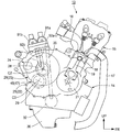
- FIG. 1 is a side view of a motorcycle according to an embodiment of the present invention.
- Fig. 2 is a right side view of an engine of the motorcycle.
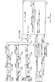
- FIG. 2 is a block diagram of a twin clutch transmission control system. It is a block diagram which shows the meshing relationship of each axis
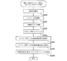
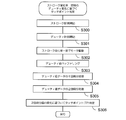
- 2 is a stroke-clutch capacity graph and a stroke-clutch hydraulic pressure graph. It is a flowchart which shows the procedure which calculates target half clutch hydraulic pressure. It is a graph which shows the method of detecting a stroke start position and a stroke end position, when driving a normally open type clutch with an electric motor. It is a graph which shows the method of detecting a stroke start position and a stroke end position, when driving a normally closed type clutch with an electric motor. It is a time chart which shows the flow of clutch control when the upswing phenomenon at the time of shift up is detected. It is a flowchart which shows the procedure of clutch 1 capacity
- FIG. 10 is a flowchart showing a flow of clutch 1 capacity correction control when a gear shift time is over. It is a flow chart which shows the procedure of presumption processing of shift completion time.
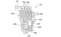
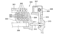
- FIG. 2 is a cross-sectional view showing a configuration of a normally closed hydraulic clutch. It is a sectional view showing the composition of an electric clutch.
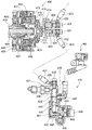
- FIG. 1 is an entire configuration diagram of a combination electric-hydraulic clutch.
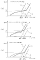
- FIG. 2 is a cross-sectional view of an electric motor of a combination electric-hydraulic clutch. It is a whole block diagram which shows the structure of an electric clutch. It is structure explanatory drawing of a cam mechanism. It is a graph which shows the relationship between the load required for the pressing operation of a clutch, and a clutch stroke.
- FIG. 1 is a side view of a motorcycle 1 as a straddle-type vehicle to which a clutch control device according to the present embodiment is applied.
- An upper portion of the front fork 3 pivotally supporting the front wheel 2 is pivotably supported by the head pipe 6 at the front end of the vehicle body frame 5 via the steering stem 4.
- a steering handle 4 a is attached to the top of the steering stem 4.
- a main frame 7 extends rearward from the rear of the head pipe 6 and continues to the pivot plate 8.
- a front end portion of a swing arm 9 is pivotally supported by the pivot plate 8 so as to be vertically pivotable, and a rear wheel 11 is pivotally supported by a rear end portion of the swing arm 9.
- a cushion unit 12 is interposed between the swing arm 9 and the vehicle body frame 5. Inside the body frame 5, an engine 13 which is a power source of the motorcycle 1 is attached.
- the engine 13 is a parallel four-cylinder engine in which the rotation center axis C1 of the crankshaft 21 is aligned with the vehicle width direction, and the cylinder 15 is erected above the crankcase 14. .
- Pistons 18 corresponding to the respective cylinders are fitted in the cylinders 15 so as to be capable of reciprocating, and the reciprocating motions of the respective pistons 18 are converted to rotational motions of the crankshaft 21 via connecting rods 19.
- a throttle body 16 is connected to the rear of the cylinder 15, and an exhaust pipe 17 is connected to the front of the cylinder 15.
- a transmission case 22 is integrally connected to the rear of the crankcase 14, and a twin clutch transmission 23 and a change mechanism 24 are accommodated in the transmission case 22.
- the transmission case 22 has a clutch case 25 on the right side in the vehicle width direction, and the twin clutch 26 of the twin clutch type transmission 23 is accommodated in the clutch case 25.
- the rotational power of the crankshaft 21 is output to the left in the vehicle width direction of the transmission case 22 via the twin clutch type transmission 23 and then transmitted to the rear wheel 11 via, for example, a chain type power transmission mechanism.
- a countershaft 29 directed in the direction of the rotation center axis C3 is disposed below the main shaft 28 disposed in the direction of the rotation center axis C2.
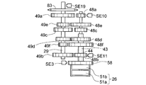
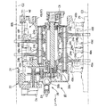
- FIG. 3 is a block diagram of a twin clutch transmission control system. 4 is a configuration diagram showing the meshing relationship between each shaft and transmission gears in an automatic transmission, FIG. 5 is a cross-sectional view of a twin clutch type transmission, and FIG. 6 is a gear shift device of the twin clutch type transmission.
- FIG. 3 is a block diagram of a twin clutch transmission control system. 4 is a configuration diagram showing the meshing relationship between each shaft and transmission gears in an automatic transmission, FIG. 5 is a cross-sectional view of a twin clutch type transmission, and FIG. 6 is a gear shift device of the twin clutch type transmission.
- FIG. 3 is a block diagram of a twin clutch transmission control system. 4 is a configuration diagram showing the meshing relationship between each shaft and transmission gears in an automatic transmission, FIG. 5 is a cross-sectional view of a twin clutch type transmission, and FIG. 6 is a gear shift device of the twin clutch type transmission.
- FIG. 3 is a block diagram of a twin clutch transmission control system. 4 is
- the twin clutch transmission control mainly includes a twin clutch transmission 23 connected to the engine 13, a gear shift device 41 having a drive mechanism 39 in the change mechanism 24, a twin clutch transmission 23, and a gear shift device It comprises an electronic control unit (ECU) 42 which controls the operation of the motor 41.
- ECU electronice control unit
- the twin clutch type transmission 23 straddles a main shaft 28 having a double structure including an inner shaft 43 and an outer shaft 44, a counter shaft 29 disposed parallel to the main shaft 28, a main shaft 28 and a counter shaft 29.
- the transmission gear group 45 is disposed, a twin clutch 26 coaxially disposed at the right end of the main shaft 28 in the vehicle width direction, and a hydraulic pressure supply device 46 that supplies hydraulic pressure to the twin clutch 26.
- a transmission 47 an assembly consisting of the main shaft 28, the countershaft 29 and the transmission gear group 45 is referred to as a transmission 47.
- the main shaft 28 is formed by inserting the right side portion of the inner shaft 43 extending laterally in the vehicle width direction of the transmission case 22 into the outer shaft 44 so as to be relatively rotatable.
- Drive gears 48a, 48b, 48c, 48d, 48e and 48f (hereinafter, 48a to 48f) of the transmission gear group 45 are distributed on the outer circumference of the inner and outer shafts 43 and 44.
- the driven gears 49a, 49b, 49c, 49d, 49e, 49f (hereinafter, 49a to 49f) for the sixth speed in the transmission gear group 45 are arranged.
- the drive gears 48a to 48f and the driven gears 49a to 49f mesh with each other between the corresponding shift speeds, and the shift gear pairs 45a, 45b, 45c, 45d, 45e, 45f (hereinafter, 45a to 45f) corresponding to the shift speeds. ) (See FIG. 5).
- Each of the speed change gear pairs 45a to 45f is set such that the reduction ratio decreases in the order of first to sixth speeds.
- the left end of the inner shaft 43 in the vehicle width direction reaches the left side wall 22a of the transmission case 22, and is rotatably supported by the left side wall 22a via a ball bearing 73.
- the right side portion of the inner shaft 43 penetrates the right side wall 22b of the transmission case 22 to face the inside of the clutch case 25, and the left and right middle portions of the inner shaft 43 similarly pass through the right side wall 22b. It is rotatably supported on the right side wall 22 b of the transmission case 22 via the middle portion and the ball bearing 77.
- the outer shaft 44 is shorter than the inner shaft 43, and the left end thereof is located at the left and right middle of the transmission case 22.
- Drive gears 48d, 48f, 48b corresponding to the even-numbered variable stages (second, fourth, and sixth speeds) are provided for the fourth speed, the sixth speed, and the like from the left at a portion of the outer shaft 44 located on the left of the right wall 22b. It is supported in the order of 2nd gear.
- drive gears 48a, 48e, 48c corresponding to odd shift speeds (1, 3, 5) are one gear from the left It is supported in the following order: for 5-speed, 3-speed.
- the left and right end portions of the countershaft 29 are rotatably supported on the left and right side walls 22a and 22b of the transmission case 22 via ball bearings 82 and 86, respectively.
- the left end portion of the countershaft 29 protrudes leftward of the left side wall 22a, and a drive sprocket 83 as a power transmission mechanism to the rear wheel 11 is attached to the left end portion.
- driven gears 49a to 49f corresponding to the respective shift speeds are supported in the same order as the drive gears 48a to 48f.
- main supply oil paths 71, 72 capable of supplying hydraulic pressure from a main oil pump (not shown) for oil pumping to each part in the engine 13 are provided respectively.
- the engine oil is appropriately supplied to the transmission gear group 45 through the main supply oil passages 71 and 72.
- the twin clutch 26 has hydraulic first and second clutches 51a and 51b coaxially arranged adjacent to each other, and the inner and outer shafts 43 and 44 are coaxially connected to the respective clutches 51a and 51b. .
- the primary driven gear 58 meshing with the primary drive gear 58a of the crankshaft 21 is coaxially provided on the clutch outer 56 shared by the clutches 51a and 51b, and the clutch outer 56 is cranked via the gears 58 and 58a.
- the rotational power from the shaft 21 is input.
- the rotational power input to the clutch outer 56 is individually transmitted to the inner and outer shafts 43 and 44 in accordance with the on-off state of each of the clutches 51a and 51b.
- the on-off state of each of the clutches 51a and 51b is individually controlled by the presence or absence of the hydraulic pressure supply from the hydraulic pressure supply device 46.
- one of the clutches 51a and 51b is brought into a connected state and the other is brought into a disconnected state, and power transmission in the transmission 47 is carried out using one of the shift gear pairs connected to one of the inner and outer shafts 43 and 44. And select one of the transmission gear pairs connected to the other of the inner and outer shafts 43 and 44 in advance, and from this state, one of the clutches 51a and 51b is disconnected and the other is connected. Then, the power transmission of the transmission 47 is switched to one using the previously selected transmission gear pair, whereby the transmission 47 is upshifted or downshifted.
- the hydraulic pressure supply device 46 includes a clutch oil pump 32 which is a hydraulic pressure generation source for the twin clutch 26, a feed oil passage 35 extending from a discharge port of the clutch oil pump 32, and the feed oil.
- the clutch oil pump 32 is provided separately from the main oil pump, and sucks in the engine oil in the oil pan 36 below the crankcase 14 and discharges it into the feed path 35.
- the oil supply path 89 is provided with an oil filter 89 dedicated to the oil path.
- the feed oil passage 35 is provided with an oil pressure sensor SE6 for detecting oil pressure and oil temperature, an oil temperature sensor SE7, and a relief valve R for controlling an increase in oil pressure in the feed oil passage 35.
- a first clutch hydraulic pressure sensor SE8 and a second clutch hydraulic pressure sensor SE9 that detect the hydraulic pressure supplied to the clutches 51a and 51b are provided in the respective supply oil paths 92a and 92b.
- the feed oil passage 35 and the first and second oil supply passages 92a and 92b can be individually communicated by the operation of the clutch actuators 91a and 91b, which are solenoid valves.
- the clutch actuators 91a and 91b which are solenoid valves.
- a relatively high hydraulic pressure from the clutch oil pump 32 is supplied to the connection side hydraulic chamber 54a of the first clutch 51a.
- the first clutch 51a is in the connected state.
- the oil supply passage 35 and the second oil supply passage 92b communicate with each other via the second clutch actuator 91b
- the hydraulic pressure from the clutch oil pump 32 is supplied to the connection side hydraulic chamber 54b of the second clutch 51b.
- the second clutch 51b is in the connected state.
- An oil pressure relief oil path 96 a having an oil pressure relief valve 95 is branched from the feed and oil path 35.
- the oil pressure relief valve 95 is actuated by the valve actuator 95a to switch between opening and closing of the oil pressure relief oil passage 96a.
- the valve actuator 95a controlled by the ECU 42 opens the oil pressure relief oil passage 96a at engine start, for example, returns the feed oil pressure from the clutch oil pump 32 to the oil pan 36, and after the engine starts, releases the oil pressure relief oil passage 96a. It shuts off to make it possible to supply the feed hydraulic pressure to the twin clutch 26.
- the hydraulic pressure from the clutch oil pump 32 is returned to the inside of the oil pan when the communication between the oil supply passage 35 and the first and second oil supply passages 92a and 92b is cut off in each of the clutch actuators 91a and 91b.
- the return oil passages 93a and 93b are respectively provided.
- the change mechanism 24 moves a plurality (four in this embodiment) of shift forks 24b in the axial direction by the rotation of the shift drum 24a arranged in parallel with the respective shafts 28 and 29, so that an interval between the main shaft 28 and the countershaft 29 is obtained.
- Each shift fork 24b is a pair extending in the main shaft 28 side and the countershaft 29 side, and their proximal ends are axially movably supported by a pair of shift fork rods 24c. There is. On the base end side of each shift fork 24b, a sliding projection 24e engaged with any of the plurality of camshafts 24d on the outer periphery of the shift drum 24a is provided. Each shift fork 24 b has its tip engaged with a slide gear (described later) of the transmission gear group 45 on the main shaft 28 side and the counter shaft 29 side. Then, when the shift drum 24a rotates, each shift fork 24b moves in the axial direction along the pattern of each cam groove 24d, and the slide gear is moved in the axial direction to change the gear of the transmission 47. It is done.
- the drive mechanism 39 provided on one end side of the shift drum 24a includes a pin gear 39a coaxially fixed to the shift drum 24a of the change mechanism 24, a worm-like barrel cam 39b engaged with the pin gear 39a, and a barrel cam 39b. And an electric motor 39c for applying power.
- the drive mechanism 39 appropriately rotates the shift drum 24 a by driving the electric motor 39 c to change the gear position of the transmission 47.
- the drive mechanism 39 is provided with a gear position sensor SE1 that detects the amount of operation of the drive mechanism 39 in order to detect the gear position of the transmission 47.
- the transmission gear meshing with the left end of the shift drum 24a is provided with a rotation angle sensor Ds for detecting the rotation angle of the shift drum 24a, and the rotation shaft and shift are provided at the right end of the shift drum 24a.
- a detent mechanism (lost motion mechanism) Dt of the drum 24a is disposed.
- the transmission 47 is a constant meshing type in which drive gears 48a to 48f and driven gears 49a to 49f corresponding to the respective gear positions are always meshed.
- Each gear is integrally fixed and axially movable with respect to the fixed shaft which can be integrally rotated with respect to the support shaft (each shaft 28, 29), a free gear which is relatively rotatable with respect to the support shaft, and the shaft It is divided roughly into various slide gears.
- the drive gears 48a and 48b are fixed gears
- the drive gears 48c and 48d are slide gears
- the drive gears 48e and 48f are free gears.
- the driven gears 49a to 49d are free gears
- the driven gears 49e and 49f are slide gears.
- the gears 48c, 48d, 49e, 49f may be referred to as slide gears
- the gears 48e, 48f, 49a to 49d may be referred to as free gears.
- slide rings Sc and Sd which can be integrally rotated and axially movable with respect to the support shaft similarly to them are integrally provided.
- the slide rings Sc and Sd are provided axially adjacent to the free gears 48e and 48f, respectively.
- the slide rings Sc and Sd are provided with slide side dogs (davos) D1c and D1d, and the free gears 48e and 48f have free side dogs (davos) D1e, corresponding to the slide side dogs D1c and D1d, respectively.
- D1 f is provided.
- slide rings Se and Sf which can be integrally rotated and axially movable with respect to the support shaft are integrally provided.
- the slide rings Se and Sf are provided axially adjacent to the free gears 49c and 49d, respectively.
- the slide rings Se and Sf are respectively provided with slide side dogs (davos) D2e and D2f, and the free gears 49c and 49d have free side dogs (davos) D2c, corresponding to the respective slide side dogs D2e and D2f. D2d is provided.
- slide side dogs (davos) D3e, D3f are provided, and in the free side gears 49a, 49b axially adjacent thereto, the slide side dogs D3e , D3f, and free side dogs (davos) D3a, D3b are provided.
- Each slide dog and free dog engage non-rotatably with each other as the corresponding slide gear (including the slide ring) and free gear are close to each other, and the slide gear and free gear are mutually engaged as they are separated.
- the ECU 42 (see FIG. 3) includes an opening degree sensor TS of the throttle valve of the throttle body 16, a storage sensor SS for detecting the storage state of the side stand, a wheel speed sensor WS of the front wheel 2, and a steering handle 4a. Gear stages of the transmission 47 by controlling the operation of the twin clutch transmission 23 and the gear shift device 41 based on information from the mode switch SW1, the gear select switch SW2, the neutral-drive changeover switch SW3 etc. Change (shift position). Each sensor signal is also transmitted to the EFI-ECU 42a that controls the fuel injection device.
- the transmission mode selected by the mode switch SW1 is a full automatic mode in which the shift position of the transmission 47 is automatically switched based on vehicle information such as vehicle speed (wheel speed) and engine speed, and a gear select switch based on the driver's intention.
- vehicle information such as vehicle speed (wheel speed) and engine speed
- gear select switch based on the driver's intention.
- the current shift mode and gear position are displayed, for example, on a meter device M provided near the steering wheel 4a.
- the neutral-drive switch SW3 the transmission 47 can be switched between a state in which power transmission can be performed at a predetermined shift speed and a neutral state.
- an engine speed sensor SE ⁇ b> 3 is disposed in the vicinity of primary driven gear 58. Further, an inner shaft rotational speed sensor SE10 for detecting the rotational speed of the inner shaft 43 is disposed in the vicinity of the drive gear 48a, and the rotational speed of the outer shaft 44 is detected in the vicinity of the drive gear 48b. An outer shaft rotational speed sensor SE11 is provided to do this. Further, in the vicinity of the countershaft 29, a countershaft rotational speed sensor SE19 is disposed. Each sensor signal is transmitted to the ECU 42 and the EFI-ECU 42a. In addition, each rotation speed sensor is not restricted to the example of this embodiment, It is possible to arrange
- the first clutch 51a connected to the transmission gear pair for the odd gear is disposed on the right side (outside in the vehicle width direction) in the clutch case 25 and for the even gear.
- the second clutch 51b connected to the transmission gear pair is disposed on the left side (inner side in the vehicle width direction) in the clutch case 25.
- Each of the clutches 51a and 51b is a wet multi-plate type having a plurality of clutch plates (the clutch disks 61a and 61b and the clutch plates 66a and 66b) alternately overlapping in the axial direction.
- Each of the clutches 51a and 51b is a hydraulic type that displaces the pressure plates 52a and 52b in the axial direction by the hydraulic pressure supplied from the outside to obtain a predetermined engagement force, and biases the pressure plates 52a and 52b toward the clutch disconnection side
- the springs 53a, 53b, the connection side hydraulic chambers 54a, 54b applying pressure to the clutch connection side to the pressure plates 52a, 52b, and the pressure plates 52a, 52b apply pressure to the clutch disconnection side, and the return thereof It has cutting side oil pressure chambers 55a and 55b for assisting the operation.
- a relatively low hydraulic pressure from the main oil pump is always supplied to the disconnecting hydraulic chambers 55a and 55b, and the connecting hydraulic chambers 54a and 54b are supplied from the hydraulic pressure supply device 46 (clutch oil pump 32).
- a relatively high hydraulic pressure is selectively and separately supplied.
- the clutches 51a and 51b share a single clutch outer 56 and have substantially the same diameter.
- the clutch outer 56 has a bottomed cylindrical shape that opens to the right, and the bottom center portion thereof is supported by the left and right intermediate portions of the outer shaft 44 so as to be relatively rotatable.
- a clutch center 57a for the first clutch 51a is disposed on the left inside of the clutch outer 56, and a clutch center 57b for the second clutch 51b is disposed on the right inside of the clutch outer 56.
- the clutch center 57 b is integrally rotatably supported at the right end of the outer shaft 44.
- a primary driven gear 58 is attached to the left side of the bottom of the clutch outer 56 via a spring damper 59, and a primary drive gear 58a of the crankshaft 21 engages with the primary driven gear 58.
- the rotational power of the crankshaft 21 is input to the clutch outer 56 through the spring damper 59.
- the clutch outer 56 rotates separately from the main shaft 28 as the crankshaft 21 rotates.
- a drive sprocket 56b for driving each oil pump is integrally rotatably provided on the left side of the primary driven gear 58 in the clutch outer 56.
- a plurality of clutch plates 61 a for the first clutch 51 a are supported integrally rotatably on the right inner periphery of the clutch outer 56.
- a plurality of clutch plates 61b for the second clutch 51b are supported so as to be integrally rotatable.
- a plurality of engagement grooves along the axial direction are formed on the outer periphery of the clutch outer 56, and a plurality of engagement protrusions corresponding to the respective engagement grooves are formed on the inner periphery of each of the clutch plates 61a and 61b. ing.
- the respective clutch projections 61a, 61b are supported on the clutch outer 56 so as to be integrally rotatable by the relative engagement of the respective engagement projections with the respective engagement grooves.
- the flange portion 64a on the left side of the clutch center 57a of the first clutch 51a is provided with an inner wall 65a rising rightward, and a plurality of clutch disks (friction plates) 66a integrally rotate on the outer periphery of the inner wall 65a. It is supported possible.
- a plurality of engaging grooves along the axial direction are formed on the outer periphery of the clutch center 57a, and a plurality of engaging projections corresponding to the engaging grooves are formed on the inner periphery of each clutch disc 66a.
- the respective clutch projections 66 are nonrotatably engaged with the respective engaging grooves, whereby the respective clutch disks 66 a are supported integrally rotatably by the clutch center 57.
- a pressure plate 52a is disposed opposite to the right side of the flange portion 64a, and between the outer peripheral side of the pressure plate 52a and the outer peripheral side of the flange portion 64a, each clutch plate 61a and each clutch disc 66a They are arranged in a stacked state alternately stacked in the direction.
- a cutting-side hydraulic chamber 55a is formed between the inner peripheral side of the pressure plate 52a and the inner peripheral side of the flange portion 64a, and the pressure plate 52a is moved to the right (the side separating from the flange portion 64a, the clutch cutting side A return spring 53a is disposed to bias the same.
- the support flange portion 67a provided on the outer periphery of the central cylindrical portion 62a on the right side of the clutch center 57a is disposed opposite to the right of the inner peripheral side of the pressure plate 52a, and the support flange portion 67a and the inner peripheral side of the pressure plate 52a
- a connection side hydraulic chamber 54a is formed and a return spring 53a is disposed.
- the flange 64b on the left side of the clutch center 57b of the second clutch 51b is provided with an inner wall 65b rising rightward, and a plurality of clutch disks 66b are integrally rotatable around the outer periphery of the inner wall 65b. It is supported.
- a plurality of engaging grooves along the axial direction are formed on the outer periphery of the clutch center 57b, and a plurality of engaging projections corresponding to the engaging grooves are formed on the inner periphery of each clutch disc 66b. . Then, the respective engaging projections are engaged with the respective engaging grooves so as not to be relatively rotatable, whereby the respective clutch disks 66b are supported so as to be integrally rotatable with the clutch center 57b.
- a pressure plate 52b is disposed opposite to the right side of the flange portion 64b, and between the outer peripheral side of the pressure plate 52b and the outer peripheral side of the flange portion 64b, each clutch plate 61b and each clutch disc 66b They are arranged in a stacked state alternately stacked in the direction.
- a cutting-side hydraulic chamber 55b is formed between the inner peripheral side of the pressure plate 52b and the inner peripheral side of the flange portion 64b, and the pressure plate 52b is moved to the right (the side separating from the flange portion 64b, the clutch cutting side A return spring 53b for biasing the same.
- the support flange portion 67b provided on the outer periphery of the central cylindrical portion 62b on the right of the clutch center 57b is disposed opposite to the right of the inner peripheral side of the pressure plate 52b, and the support flange portion 67b and the inner peripheral side of the pressure plate 52b
- a connection side hydraulic chamber 54b is formed and a return spring 53b is disposed.
- a first supply oil passage 92a, a second supply oil passage 92b, and an in-cover main supply oil passage 71a are respectively provided on a clutch cover 69 that constitutes the right side of the clutch case 25. Further, in the right hollow portion 43a of the inner shaft 43, oil passages that individually communicate with the oil passages 92a, 92b, 71a are appropriately formed.
- the hydraulic pressure from the clutch oil pump 32 can be supplied to the connection-side hydraulic chamber 54b of the second clutch 51b through the first supply oil passage 92a and the like. Further, the hydraulic pressure from the main oil pump can be supplied to the cut-off hydraulic chamber 55a of the first clutch 51a through the main supply oil passage 71 in the cover and the like. Further, the hydraulic pressure from the clutch oil pump 32 can be supplied to the connection-side hydraulic chamber 54a of the first clutch 51a through the second supply oil passage 92b etc., and the main supply oil is supplied to the disconnect-side hydraulic chamber 55b of the second clutch 51b. The hydraulic pressure from the main oil pump can be supplied through the passage 71 and the like.
- the pressure plates 52a and 52b are displaced to the right by the biasing force of the respective return springs 53a and 53b, and the clutch plates 61a and 61b and each each
- the clutch engagement state in which the frictional engagement of the clutch disks 66a and 66b is released is achieved.
- the biasing force of the return springs 53a, 53b and the hydraulic pressure of the disconnecting hydraulic chambers 55a, 55b act on the pressure plates 52a, 52b.
- the clutch is disengaged as described above. That is, the twin clutch 26 according to the present embodiment is a “normally open type” in which the clutch is disengaged when no control is performed.
- first clutch 51a in a state where the engine is operating and a relatively high hydraulic pressure is supplied from the hydraulic pressure supply device 46 to the connection side hydraulic chamber 54a, the hydraulic pressure of the disconnect side hydraulic chamber 55a and the biasing force of the return spring 53a are resisted.
- Pressure plate 52a moves to the left (flange portion 64a side, clutch connection side), and each clutch plate 61a and each clutch disc 66a are narrowed and frictionally engaged with each other, whereby the clutch outer 56 and the clutch center 57a are engaged. And the clutch can be engaged.
- the second clutch 51b in a state where the engine is operating and a relatively high hydraulic pressure is supplied from the hydraulic pressure supply device 46 to the connection side hydraulic chamber 54b, the hydraulic pressure of the cutting side hydraulic chamber 55b and the biasing force of the return spring 53b are used.
- the pressure plate 52b moves to the left (flange portion 64b side, clutch connection side), and the clutch plates 61b and the clutch disks 66b are pinched and frictionally engaged with each other, whereby the clutch outer 56 and the clutch are engaged.
- the clutch In this state, the clutch is in a state of being able to transmit torque with the center 57b.
- the engine oil supplied to the disconnecting hydraulic chambers 55a and 55b of the clutches 51a and 51b is led to the outside of the hydraulic pressure chamber through oil passages appropriately formed in the inner wall portions 65a and 65b and the like, and the outer periphery of the inner wall portions 65a and 65b
- the clutch plates 61a and 61b and the clutch disks 66a and 66b are appropriately supplied.
- the hydraulic pressure in the disconnecting hydraulic chambers 55a, 55b is maintained at a predetermined low pressure, and each clutch in each of the clutches 51a, 51b is in the disconnected state. Lubricity and cooling of the plates 61a, 61b and the clutch disks 66a, 66b are improved.
- both of the clutches 51a and 51b are clutches It is kept disconnected. Then, for example, when the side stand is stored or each switch SWA, SW2, SW3 is operated, the transmission 47 starts the first gear (start gear, transmission gear pair 45a) from the neutral state as preparation for start of the motorcycle 1. In this state, the first clutch 51a is brought into the clutch connection state through the half clutch, for example, and the motorcycle 1 is started.
- the motorcycle 1 When the motorcycle 1 travels, only one of the clutches 51a and 51b corresponding to the current shift position is in the connected state, and the other is in the disconnected state. Thus, power transmission is performed via one of the inner and outer shafts 43 and 44 and any one of the shift gear pairs 45a to 45f.
- the ECU 42 controls the operation of the twin clutch transmission 23 based on the vehicle information, and creates in advance a state in which power transmission can be performed using the transmission gear pair corresponding to the next shift position.
- pre-shift an operation for creating this state is referred to as "pre-shift”.
- the next shift position will be an even gear (or odd gear).
- a preliminary shift is performed to enable power transmission using a shift gear pair.
- the first clutch 51a is in the connected state but the second clutch 51b (or the first clutch 51a) is in the disconnected state, the outer shaft 44 (or the inner shaft 43) and the even gear (or odd gear) The engine output is not transmitted to the shift gear pair.
- the first clutch 51a (or the second clutch 51b) is disconnected and the second clutch 51b (or the first clutch 51a) is connected only, It switches to the power transmission using the transmission gear pair corresponding to the next shift position selected in advance.
- the twin clutch type transmission 23 supplies a slight hydraulic pressure as a "preload" to the connection-side hydraulic chamber of the clutch (51a or 51b) in the disconnected state during normal travel with a constant gear position, thereby clutching the clutch It is configured to operate a small amount to the connection side.
- This minute hydraulic pressure corresponds to a hydraulic pressure that is at least the minimum necessary to fill the mechanical play of the clutch, in other words, a hydraulic pressure that corresponds to the force of the return spring of the clutch.
- connection side clutch in a connected state at the time of normal operation with constant speed, the parts on the crankshaft 21 side (parts that rotate integrally with the primary driven gear 58, ie, the clutch outer 56, and the clutch plate 61a or 61b) And the parts on the transmission 47 side (parts that rotate integrally with the main shaft 28, ie, the clutch centers 57a or 57b, the clutch disks 66a and 66b, etc.) integrally rotate with each other.
- the clutch (disconnection side clutch) in the disconnected state the component on the crankshaft 21 side idles relative to the component on the transmission 47 in the stopped state.
- each of the clutches 51a and 51b the engagement groove on the outer periphery of the clutch outer 56 and the engagement projection on the outer periphery of each of the clutch plates 61a and 61b, and the engagement groove on the outer periphery of each clutch center 57a and 57b and each clutch disc 66a, Between the engaging projection on the inner periphery of 66b, there is mechanical clearance (rotational clearance) in the rotational direction when no driving force (torque) is transmitted, but the clutch in the disconnected state is clutched as described above By operating a small amount to the side, a minute torque is applied from the part on the crankshaft 21 side to the part on the transmission 47 side. This makes it possible to close the play in the rotational direction and to suppress the generation of sound during normal operation based on the play.
- the clutch control device is characterized in that the following four controls can be made in addition to the above-described control of filling the play by applying the pre-load. (1) Control that enables accurate hydraulic control in the half clutch region without using a clutch stroke sensor etc.
- FIG. 7 is a block diagram showing the configuration of the ECU 42 as a clutch control device according to an embodiment of the present invention and its peripheral devices.
- the same reference numerals as above indicate the same or equivalent parts.
- the ECU 42 includes a shift control unit 100, a clutch hydraulic pressure detection unit 110, a stroke start hydraulic pressure detection unit 120, a stroke end hydraulic pressure detection unit 130, a ratio detection unit 140, a clutch control correction amount calculation unit 150, and standby for preliminary shift change. And a time setting unit 160.
- the shift control unit 100 includes a shift map 101 and a timer 102.
- the timer 102 can measure various times such as the time relating to the speed change operation in addition to the calculation of the engine rotation speed and the like.
- the clutch control correction amount calculation unit 150 includes a basic clutch capacity calculation unit 200, an overrun clutch capacity correction unit 210, a shift time over clutch capacity correction unit 220, and a target clutch capacity calculation unit 230.
- a target half clutch hydraulic pressure calculation unit 240 is included.
- the transmission control unit 100 includes an oil temperature sensor SE7, a gear position sensor SE1, an engine rotation number sensor SE3, an inner shaft rotation number sensor SE10, an outer shaft rotation number sensor SE11, a countershaft rotation number sensor SE19, and a throttle opening sensor TS Signals from the intake air temperature sensor SE12 and the atmospheric pressure sensor SE13 are respectively input. Further, signals from the first clutch hydraulic pressure sensor SE8 and the second clutch hydraulic pressure sensor SE9 are input to the transmission control unit 100 via the clutch hydraulic pressure detection unit 110.
- shift control unit 100 performs shift control motor 39c according to shift map 101 formed of a three-dimensional map or the like based on gear position sensor SE1, engine speed sensor SE3, throttle opening sensor TS and vehicle speed information.
- the first clutch actuator 91a and the second clutch actuator 91b are driven to execute a gear change operation.
- the shift control unit 100 also detects a shift state such as a shift signal being generated and shifting during automatic shift control according to the shift map 101 and semi-automatic shift by the operation of the gear select switch SW2.
- FIG. 8 is referred to.
- FIG. 8 is a block diagram showing the calculation procedure of the target clutch hydraulic pressure Pt.
- the clutch capacity correction amount calculation unit 150 finally calculates the target clutch hydraulic pressure Pt by various arithmetic processing, and the target clutch hydraulic pressure Pt is supplied to the first and second clutches 51a and 51b. 1, drive the second clutch actuators 91a and 91b.
- the target clutch hydraulic pressure Pt is a hydraulic pressure at which the clutch is completely connected, and is calculated using the target clutch capacity C and the actual return spring load F according to the following equation shown in procedure F4.
- Pt ((target clutch capacity C / clutch friction coefficient ⁇ ⁇ number of clutch plates n ⁇ effective radius r) + actual return spring load F) / clutch piston pressure receiving area S
- step F1 the target clutch capacity C is corrected based on the clutch capacity correction value H1 at the occurrence of overrun and the clutch capacity correction value H2 at the shift over time with respect to the basic target clutch capacity CK calculated by the basic clutch capacity calculation unit 200. Is calculated by further multiplying the primary ratio (the reduction ratio from the crankshaft to the main shaft) in step F2.
- the basic target clutch capacity CK is a torque that can transmit the rotational drive power without causing the clutch to slip, that is, a value larger by an arbitrary amount ⁇ (for example, 20% of the engine torque) than the currently generated engine torque.
- Ru The arbitrary amount ⁇ is a parameter that affects the shift time and the shift feeling, and an arbitrary numerical value according to the situation is set.
- the engine torque estimation unit 201 calculates an engine torque estimated value based on information such as the throttle opening degree, the engine speed, the intake air temperature, the atmospheric pressure and the like.
- the clutch control correction amount calculation means 150 drives and controls the first clutch actuator 91 a and the second clutch actuator 91 b using the calculated actuator drive current. As a result, it is possible to prevent the change in the traveling feeling even when a change in the state of the clutch occurs due to a change in the characteristics of the return spring.
- the stroke end oil pressure Pe used to calculate the actual return spring load F is detected by the stroke end oil pressure detection unit 130. Furthermore, in the present embodiment, by detecting the stroke start oil pressure Ps by the stroke start oil pressure detection unit 120, calculation of the target half clutch oil pressure Ph necessary to create an arbitrary half clutch state separately from the target clutch oil pressure Pt. Is configured to be possible.
- a method of detecting the stroke start oil pressure Ps and the stroke end oil pressure Pe will be described.
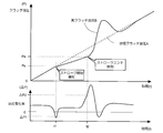
- FIG. 9 is a graph showing the transition of the clutch hydraulic pressure when the clutch is driven in the connection direction.
- the target clutch hydraulic pressure A is indicated by a broken line
- the actual clutch hydraulic pressure B detected by the clutch hydraulic pressure detection unit 110 is indicated by a solid line.
- the actual clutch hydraulic pressure B exceeds the biasing force of the return spring and the clutch starts a stroke, and the rise degree of the actual clutch hydraulic pressure B shifts to a slight increase after swinging slightly in a negative direction Do.
- the clutch plates abut each other, and the actual clutch hydraulic pressure B rises sharply by reaching a position (stroke end position) where the clutch can not travel any longer (stroke end position). After exceeding, it converges to the target clutch hydraulic pressure A.
- the change in the actual clutch hydraulic pressure B it can be estimated and detected that the clutch has reached the stroke start position and the stroke end position.
- the amount of change is determined from the differential value of the actual clutch hydraulic pressure B, and it is determined that the clutch has started a stroke when the amount of change exceeds a predetermined negative predetermined value ⁇ P1 (smaller than ⁇ P1). On the other hand, when the amount of change exceeds a predetermined positive predetermined value ⁇ P2, it is determined that the clutch has reached the stroke end position.
- the actual clutch hydraulic pressure Ps at time t1 is detected as the hydraulic pressure value at the start of stroke because the amount of change of the actual hydraulic pressure exceeds the negative predetermined value ⁇ P1 at time t1, and at time t2 Since the amount of change exceeds the positive predetermined value ⁇ P2 (becomes larger than ⁇ P2), the actual clutch hydraulic pressure Pe at time t2 is detected as the hydraulic pressure value at the stroke end.
- the twin clutch 26 slides the pressure plates 52a and 52b in the clutch connecting direction against the biasing force of the return springs 53a and 53b by supplying the hydraulic pressure to the connection side hydraulic chamber. It is configured to let you Therefore, for example, when the clutch plates wear and the stroke amount until the clutch plates abut each other increases, or when the return spring is replaced with a product having a large resilient force, it is necessary to bring the clutch plates into contact with each other. The load will increase. When such a change occurs, if the same hydraulic pressure as that before the change is generated, the time from the start of driving the clutch to the connection state becomes longer, and the clutch torque capacity becomes excessive or insufficient. There is a possibility that the driving feeling may change at the time of starting or shifting.
- the control correction amount at the stroke end position is calculated by detecting the load when the clutch plates abut, that is, when the clutch reaches the "stroke end position" where the stroke can not travel any longer. Is configured as.
- the control correction amount in the semi-clutch region is calculated by detecting the load at the time when the clutch reaches the "stroke start position" at which the stroke starts. It is possible to do that.
- a method of correcting the control amount in the half clutch region using the values of the stroke start oil pressure Ps and the stroke end oil pressure Pe will be described.
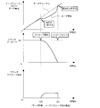
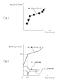
- FIG. 10 is a stroke-clutch displacement graph (a) and a stroke-clutch hydraulic pressure graph (b).
- the stroke-clutch capacity graph (a) shows the relationship between the clutch stroke and the clutch capacity depending on the spring characteristics of the return springs 53a, 53b.
- the stroke amount of the clutch may be set 3 mm before the stroke end (full stroke position) X mm.
- the stroke-clutch oil pressure graph (b) approximates the relationship between the hydraulic pressure supplied to the clutch and the stroke based on the stroke start oil pressure Ps and the stroke end oil pressure Pe described above.
- the stroke start oil pressure Ps is 50 kPa
- the stroke end oil pressure is 200 kPa
- the clutch oil pressure Px at a stroke 7 mm 3 mm before the stroke end is Prove.
- the clutch hydraulic pressure Px corresponds to the target half clutch hydraulic pressure Ph necessary to generate the target half clutch capacity 5 Nm, and is calculated by the following calculation formula.
- the target half clutch hydraulic pressure Ph thus calculated is applied in place of the target clutch hydraulic pressure Pt when setting the clutch capacity in a predetermined half clutch state (see step F4 in FIG. 8).
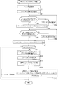
- FIG. 11 is a flowchart showing a procedure for calculating the target half clutch hydraulic pressure Ph.
- step S1 detection of the clutch hydraulic pressure is started by the clutch hydraulic pressure detection unit 110 (see FIG. 7).
- step S2 the clutch on which the calculation of the target half clutch hydraulic pressure Ph is to be performed is driven in the connection direction.
- the calculation process of the target half clutch hydraulic pressure can be executed alternately for both clutches if the transmission is in the neutral state.
- the transmission is in a state in which a predetermined number of gear steps is selected, including during traveling, it is possible to execute the clutch on the disconnected side.
- step S3 it is determined by the stroke start hydraulic pressure detection unit 120 (see FIG. 7) whether or not the rate of change of the clutch hydraulic pressure is lower than a negative predetermined value ⁇ P1. If an affirmative determination is made in step S3, the process proceeds to step S4, and the clutch hydraulic pressure Ps at that time is stored as "stroke start hydraulic pressure”.
- step S6 it is determined by the stroke end hydraulic pressure detection unit 130 (see FIG. 7) whether or not the rate of change of the clutch hydraulic pressure exceeds the positive predetermined value ⁇ P2.
- step S7 the clutch hydraulic pressure Pe at that time is stored as the "stroke end hydraulic pressure". If the negative determination is made in step S3, the drive of the clutch is continued in step S5 and the process returns to step S3, and if the negative determination is made in step S6, the drive of the clutch is continued in step S8 and the process proceeds to step S6.
- step S9 it is determined by the oil temperature sensor SE7 whether or not the oil temperature of the hydraulic oil of the clutch is equal to or less than a predetermined value (for example, 50 degrees). This determination is made because the oil temperature is closely related to the viscosity change of the hydraulic oil.
- a predetermined value for example, 50 degrees.
- control is directly performed assuming that it is not suitable for calculation of the clutch control correction amount. finish.
- the determination in step S9 is negative, that is, if it is determined that the oil temperature exceeds the predetermined value and the state is suitable for calculation of the clutch control correction amount, the process proceeds to step S10.
- step S10 the clutch control correction amount is calculated by executing the arithmetic processing shown in FIG. 8 using the hydraulic pressure values Ps and Pe stored in steps S4 and S7.
- step S11 the target half clutch capacity is set, and in step S12, the target half clutch stroke is derived from the graph (b) shown in FIG.
- step S13 the target half clutch hydraulic pressure calculation unit 240 calculates the target half clutch hydraulic pressure Ph using the above-described calculation formula, and the series of control is ended.
- the clutch control device As described above, according to the clutch control device according to the present embodiment, there is a change in the clutch control amount at the stroke end position by detecting the stroke end position of the clutch based on the change in the actual clutch oil pressure. However, it becomes possible to execute appropriate clutch control. Also, by detecting the hydraulic pressure at the stroke start position in addition to the hydraulic pressure at the stroke end position, appropriate clutch control can be performed even in a partially engaged clutch state between the stroke start position and the stroke end position. It becomes possible.
- the method of detecting the stroke start position and the stroke end position of the clutch as described above can also be applied to an electric clutch using an electric motor as a drive source.
- FIG. 12 is a graph showing a method of detecting a stroke start position and a stroke end position when driving a normally open clutch by an electric motor.
- the states of the motor duty and the motor current, the clutch stroke, and the clutch stroke speed are shown sequentially from the top.
- it is estimated to detect that the clutch has reached the stroke start position and the stroke end position.
- the amount of change (not shown) in the motor current is determined from the differential value of the motor current, and it is determined that the clutch has started a stroke when the amount of change exceeds a predetermined negative predetermined value.
- the amount of change of the motor current exceeds a predetermined positive predetermined value, it can be determined that the clutch has reached the stroke end position.
- FIG. 13 is a graph showing a method of detecting a stroke start position and a stroke end position when driving a normally closed clutch by an electric motor.
- the stroke start position and the stroke end position can be determined in the same manner as described above even in the case of a normally closed type in which the clutch is in full stroke, that is, in a clutch connected state when the electric motor is not energized.
- the clutch stroke is S2 in the full stroke state. Then, after the application of the motor duty shown by the broken line in the drawing is started, the motor does not rotate due to the biasing force of the return spring for a predetermined period, and the clutch does not start the stroke. At this time, the actual motor current value shown by a solid line in the figure linearly increases along the motor duty.
- the stroke start position and the stroke end position can be detected based on the amount of change in the motor current value.
- FIG. 14 is a time chart showing the flow of clutch control when the "burn-up phenomenon" at the time of shift-up is detected.
- the "blow up phenomenon” refers to a clutch of the other side during a shift operation during normal traveling after the start of the vehicle, that is, when switching the connection side clutch of the twin clutch from one side to the other side This refers to the phenomenon that the engine rotation speed rises (blowing) due to a lack of capacity causing clutch slippage.
- the present embodiment is characterized in that the detection of the rising phenomenon is performed based on the ratio of the rotational speed of the crankshaft to the rotational speed of the countershaft, that is, the change in the input / output ratio.
- FIG. 14 shows the flow of clutch control when upshifting from the second gear to the third gear, that is, when the connection side clutch is switched from the second clutch to the first clutch.
- the input / output ratio R is calculated by the ratio detection unit 140 by dividing the engine rotation speed detected by the engine rotation speed sensor SE3 by the countershaft rotation speed detected by the countershaft rotation speed sensor SE19.
- the input / output ratio R is a fixed value for each shift position while the clutch is completely connected, and takes a value between each fixed value when the clutch is not completely connected. In the present embodiment, by utilizing this characteristic, by observing the change in the input / output ratio R, a racing phenomenon at the time of gear shifting, that is, clutch slip at the gear shifting is detected.
- the vehicle is in the state of selecting the second gear and accelerating. During this time, if the clutch is in the engaged state, only the engine speed changes and the input / output ratio remains at R2. Then, at time t30, holding of the second clutch to the first clutch is started in association with the gear shift operation.
- the second clutch in order to suppress torque fluctuation at the time of gear shift, the second clutch immediately shifts the target clutch capacity at clutch change-over to the disconnected state, while the first clutch shifts to the engaged state in stages. It is set to.
- the input / output ratio R2 should start decreasing rapidly from the time t30 toward the input / output ratio R3 of the third speed. Then, after the start of the shift control, the input / output ratio R rises, and at time t31, the racing determination ratio Rh is reached.
- the upstroke phenomenon is detected when the input / output ratio R reaches a predetermined upstroke determination ratio Rh during the shift control.
- FIG. 15 is a flow chart showing a procedure of clutch 1 capacity correction control at the time of occurrence of a surge according to the present embodiment.
- the overrun clutch 1 capacity correction control is executed by the overrun clutch capacity correction unit 210 (see FIG. 7), and is roughly divided into three steps.
- step S20 the correction coefficient base Kb is derived using a predetermined data table.
- step S21 the correction coefficient K is calculated, and in step S22, the target clutch capacity C is corrected using the correction coefficient K, and the series of control is ended.
- similar correction control can be performed on the second clutch.
- the blowup detection unit 211 includes a ratio detection unit 140 (see FIG. 7). Then, the on-occurrence clutch capacity correction unit 210 calculates the on-occurrence clutch capacity correction value H1 according to the over-speed detection signal and the ratio change amount input from the over-speed detection unit 211.
- FIG. 16 is a flowchart showing the procedure for deriving the correction coefficient base Kb. This flowchart corresponds to control at the time of shifting from the even gear to the odd gear by switching from the second clutch to the first clutch, for example, when shifting from second gear to third gear.
- step S30 it is determined whether or not a shift is in progress. When an affirmative determination is made in step S30, it is determined in step S31 whether or not there is permission for ratio calculation.
- step S32 it is determined whether the shift operation is an upshift or downshift, and if it is determined that the shift up is performed, the process proceeds to step S33.
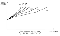
- step S34 the correction coefficient base Kb is derived using the ratio change amount ⁇ R, each information on the current shift position, and the correction coefficient base table shown in FIG.
- step S41 as in step S34, the correction coefficient base Kb is derived using the ratio change amount ⁇ R, each information on the current shift position, and the correction coefficient base table.
- the ratio change amount ⁇ R is calculated by subtracting the current ratio from the shift start ratio.
- step S30 If a negative decision is made in step S30, that is, if it is determined that shifting is not in progress, then the process proceeds to step S35.
- "not in the middle of a shift” corresponds to a state in which the clutch disconnection is completed and the clutch disengagement side gear is switched to the neutral state.
- step S31 the process proceeds to step S36 on the assumption that the ratio calculation permission associated with the release of the second clutch has not been issued although there is a shift, and it is determined whether the second clutch is released. .
- it is set to determine that the second clutch has been released by issuing a disconnection command to the currently connected clutch, that is, by issuing a signal for closing the clutch actuator.
- FIG. 18 is a flowchart showing a procedure of calculation processing of the correction coefficient K.
- step S50 it is calculated whether or not a shift is in progress, and if an affirmative determination is made, the process proceeds to step S51.
- step S51 it is determined whether the value of the correction coefficient base Kb has exceeded the value of the correction coefficient K.
- step S52 the correction coefficient K is set to the value of Kb, and the series of control is ended.
- the correction coefficient K is already set, it is possible to update the correction coefficient K only when the newly derived correction coefficient base Kb exceeds the correction coefficient K.
- step S52 is skipped and the series of control is performed. Finish.
- FIG. 19 is a flow chart showing the flow of the upshift detection process during a shift.
- step S61 it is determined whether or not a shift is in progress, and if an affirmative determination is made, the process proceeds to step S62. On the other hand, when a negative determination is made in step S61, the process proceeds to step S63, the over-speed detection signal is cleared, and the series of control is ended.
- step S64 it is determined whether or not an upwind state has been detected. If a negative determination is made in step S65, it is determined whether the ratio change amount ⁇ R has exceeded a predetermined value. If an affirmative determination is made in step S65, the process proceeds to step S66, the overheat detection signal is set, and the series of control is ended. On the other hand, when an affirmative determination is made in step S64, steps S65 and 66 are skipped, and when a negative determination is made in step S65, step S66 is skipped and a series of control is ended.
- FIG. 20 is a flow chart showing the detailed flow of the clutch capacity correction process at the time of the occurrence of a surge.
- step S70 it is determined whether or not a blowup detection signal is set. If an affirmative determination is made in step S70, the process proceeds to step S71, and a correction coefficient base Kb is derived using the correction coefficient base table.
- step S70 If a negative determination is made in step S70, the correction coefficient K is set to 1.0 (no correction) in step S73, and the process proceeds to step S75. As shown in FIG. 8, the value of the calculated clutch displacement correction value H1 at the time of rising is used when calculating the target clutch capacitance C.
- FIG. 21 is a time chart showing the flow of clutch control at the time of clutch changeover.
- the engine speed, the input / output ratio, and the clutch oil pressure are shown in order from the top. If the clutch capacity on the connection side is insufficient at the time of clutch changeover, for example, although the blow up of the engine speed due to acceleration does not occur, the time from the shift start to the shift end is longer than planned with the slip phenomenon of the clutch. There is a possibility of In the present embodiment, when the time taken for the shift operation exceeds a predetermined shift completion maximum time, the clutch hydraulic pressure on the connection side is increased to forcibly complete the shift operation.
- the example of this figure corresponds to traveling in the second speed, that is, shifting up to the third speed from the state in which the second clutch is connected and the first clutch is disconnected.
- this supply of hydraulic pressure for switching the first clutch which has been cut into the connected state until is initiated begins to rise clutch oil pressure from the cutting oil pressure P A Do.
- the clutch oil pressure of the second clutch which has been connected so far starts decreasing from the connection oil pressure P B in accordance with the shift command.
- the engine rotational speed and the input / output ratio become the target engine rotational speed and the target ratio indicated by the broken line.
- the hydraulic pressure supplied to the first clutch is increased at time t42 to complete the clutch connection, but the actual hydraulic pressure does not increase even after time t42, indicating that the clutch connection is not completed.
- the graph of the engine rotational speed shows the engine rotational speed Ne1 at the start of the shift and the engine rotational speed Ne2 when the shift to the third speed is completed while maintaining the vehicle speed at the start of the shift.
- the clutch control device starts correction control to forcibly increase the hydraulic pressure of the first clutch in response to the passage of the shift completion maximum time Tmax calculated at the start of the shift.
- the clutch connection is completed. Note that the actual hydraulic pressure of the first clutch is then increased until it reaches the connection hydraulic pressure P B at time t45. Further, the correction for increasing the clutch oil pressure is set such that the correction amount is increased according to the elapsed time from time t43 when the shift completion maximum time Tmax has elapsed.
- FIG. 22 is a flow chart showing the flow of the clutch 1 capacity correction control when the shift time is over.
- the shift time over time clutch 1 capacity correction control is roughly divided into two steps. First, in step S80, the shift completion time Th is estimated using a plurality of calculation formulas. Then, in step S81, the clutch 1 capacity correction coefficient Kover during shift time over is calculated, and the series of control is ended.
- the value of the correction coefficient Kover thus calculated is used by the clutch control correction amount calculation unit 150 (see FIG. 7) to correct the clutch control amount.
- FIG. 23 is a flowchart showing a procedure of estimation processing of the shift completion time.
- step S90 it is determined whether or not a shift is in progress. If an affirmative determination is made in step S90, the process proceeds to step S91, in which it is determined whether the shift completion time has been calculated. If a negative determination is made in step S90, or if a positive determination is made in step S91, the control ends as it is not necessary to estimate the shift completion time.
- step S93 the shift time ⁇ Ne is derived using the data table shown in FIG. FIG. 24 is a data table showing the relationship between the clutch shift torque Qh and the shift ⁇ Ne, and it is possible to derive a predetermined shift ⁇ Ne by applying the clutch shift torque Qh calculated in step S92. .
- step S94 values of (1) shift completion time Th, (2) shift completion maximum time Tmax, and (3) shift completion minimum time Tmin are calculated.
- the offset value is a value arbitrarily determined so that the shift completion time will not be too short.
- the shift completion maximum time Tmax and the shift completion minimum time are calculated by multiplying the calculated Th by the coefficient Kmax and the coefficient Kmin (Kmax> Kmin), which are arbitrarily determined.
- the correction control is executed to increase the hydraulic pressure of the first clutch when the elapsed time from the shift start exceeds the maximum shift completion time Tmax.
- FIG. 25 is a flow chart showing a procedure for deriving the correction coefficient Kover.
- step S100 it is determined whether or not a shift is in progress, and if an affirmative determination is made, the process proceeds to step S101.
- step S101 it is determined whether the time elapsed from the start of the shift (shift over time) has exceeded the shift completion maximum time Tmax.
- step S102 the correction coefficient Kover is derived using the data table shown in FIG. 26 that indicates the relationship between the shift over time and the correction coefficient Kover.
- the above-described process of deriving the correction coefficient Kover is executed by the clutch capacity correction unit 220 when the shift time is over.
- FIG. 27 is a flow chart showing a procedure of preliminary shift waiting time setting processing.
- the preliminary shift waiting time setting process is executed by the preliminary shift waiting time setting unit 160 (see FIG. 7), and is roughly divided into two steps. First, in step S110, determination of a gear replacement request is performed. Then, in step S111, a clutch off determination time is derived, and the series of control ends.
- a weak hydraulic pressure for closing the gap between the gears on the disconnecting clutch in order to reduce gear shifting noise during normal travel that is, when the clutch is switched.
- preload when this preload is supplied, a striking sound is generated at the time of gear operation by the preliminary shift. Therefore, it is necessary to release the preload before preliminary gearshifting.
- the clutch actuator is switched to the clutch disconnection side while the engine is rotating, the actual hydraulic pressure does not instantaneously decrease due to the influence of centrifugal force. It is necessary to wait for the execution of the preparatory shift until it falls.
- the "preliminary shift waiting time" corresponds to the "clutch off determination time" derived in step S111.
- the reason why the actual hydraulic pressure is not instantaneously reduced due to the influence of the centrifugal force even if the clutch actuator is switched to the clutch disengagement side during the rotation of the engine is as follows.
- the hydraulic pressure related to the clutch connection is controlled by the pressure balance between the connection-side hydraulic chamber (piston chamber) that supplies the hydraulic pressure and the disconnect-side hydraulic chamber (cancel chamber) that pulls the hydraulic pressure.
- the centrifugal force received by the rotation of the main shaft) is offset by the pressure balance of both chambers, but in a transient state where the oil pressure is supplied or removed, a temporary imbalanced state occurs, and the oil pressure is supplied.
- FIG. 28 is a flowchart showing the procedure of the gear replacement request determination process.
- step S120 the hydraulic pressure determination of the first clutch is performed
- step S121 the hydraulic pressure determination of the second clutch is performed.
- the clutch hydraulic pressure determination includes an on determination and an off determination.
- the gear replacement operation is performed.
- FIG. 29 is a sub-flow showing a procedure of clutch hydraulic pressure determination.
- step S140 it is determined whether the clutch hydraulic pressure determination is in the on state determination or in the off state determination. If the on state determination is in progress, the process proceeds to step S141.
- step S141 it is determined whether or not the clutch hydraulic pressure is equal to or less than the off determination hydraulic pressure. If the positive determination is made, the process proceeds to step S142. According to the determination in step S141, after detecting that the hydraulic pressure detected by the hydraulic pressure sensors SE8 and SE9 has fallen below the predetermined value, it is possible to calculate the waiting time until the preliminary shift.
- step S142 it is determined whether or not the counter value C by the timer is 0. If an affirmative determination is made, the process proceeds to step S144.
- step S144 the clutch off determination time is determined using a data table described later. Here, the subflow of FIG. 30 is referred to.
- FIG. 30 is a sub-flow showing a procedure of clutch off determination time determination processing.
- step S160 it is determined whether the shift operation is upshifting or downshifting, and if it is determined to be upshifting, the process proceeds to step S161 and the clutch is turned off using the upshifting data table shown in FIG. The determination time is derived.
- step S162 the clutch off determination time is derived using the data table for downshifting shown in FIG.
- the clutch off determination time tables for upshifting and downshifting are three-dimensional data tables showing the relationship between the main shaft rotational speed, the oil temperature, and the clutch off determination time, respectively.
- the main shaft rotational speed is either the rotational speed of the inner shaft 43 or the outer shaft 44, depending on the gear position.
- the clutch off determination time is set to be longer as the main shaft rotational speed is higher and to be shorter as the oil temperature is higher. Further, in the present embodiment, the clutch off determination time applied at the time of shift down is set to be longer than the clutch off determination time applied at the time of shift up. As a result, while the engine speed is reduced at the time of shift up, the clutch off determination time is set corresponding to the increase of the engine speed at the time of shift down and the influence of the centrifugal force becomes large. .
- step S146 it is determined whether the counter value C has become equal to or greater than the clutch off determination time.
- the process proceeds to step S147, the counter value C is set to 0 and clutch determination is off determination. End a series of control.
- step S140 determines whether the clutch hydraulic pressure is greater than or equal to the on determination hydraulic pressure.
- step S148 determines whether the clutch hydraulic pressure is greater than or equal to the on determination hydraulic pressure.
- step S151 it is determined whether the counter value C has reached a predetermined clutch on determination time or more. If the determination is affirmative, the process proceeds to step S152.
- step S152 the counter value C is set to 0, and the clutch determination is turned on to end a series of control.
- step S122 when the hydraulic pressure determination of both clutches is completed in steps S120 and S121, the process proceeds to step S122, and it is determined whether or not the second clutch holding gear is replaced. If an affirmative determination is made in step S122, the process proceeds to step S123, it is determined whether a hydraulic pressure OFF determination of the second clutch has been completed, and if an affirmative determination is made, the process proceeds to step S124.
- step S122 and S123 when performing a preliminary shift to an even gear (for example, fourth gear) while traveling with an odd gear (for example, third gear), 2 Corresponds to releasing the preload applied to the clutch. If a negative determination is made in step S123, the process returns to the determination in step S123.
- step S122 when a negative determination is made in step S122, the process proceeds to step S125, and it is determined whether or not replacement of the first clutch holding gear is performed.
- step S125 the process proceeds to step S126, where it is determined whether an oil pressure off determination of the first clutch has been completed, and when an affirmative determination is made, the process proceeds to step S124.
- the preload applied to the first clutch is released when executing the preliminary shift to the odd gear while traveling with the even gear. It corresponds. If a negative determination is made in step S126, the process returns to the determination in step S126.
- step S124 it is determined whether or not there is a change in the target gear position, and a negative determination is made, that is, when there is a change in the target gear position, the process proceeds to step S127.
- step S130 the process proceeds to step S130, where it is determined that there is no gear replacement request, and the series of control ends.
- step S127 it is determined whether or not the target gear position is on the lower speed side than the current gear position, and if a positive determination is made, a gear replacement request in the shift down direction is issued in step S128, that is, preliminary shift Is executed to end a series of control. On the other hand, when a negative determination is made in step S127, a gear replacement request in the up-shifting direction is issued in step S129, and the series of control is ended.
- the twin clutch type transmission 23 releases the engagement of the dog clutch of the transmission gear of the disconnection clutch after releasing the clutch on the disconnection side after the shift is completed, and the dog clutch engages with any gear
- the control (N shift change) to bring the vehicle into the neutral state is executed.
- the above-described waiting time can be applied to this N-shift, and can be used for various shift operations in a transient state affected by engine centrifugal force.
- FIG. 33 is a flowchart showing the procedure of the process of determining the traveling mode when a failure occurs in the transmission. If any failure occurs in the transmission, if it is set so that traveling can not be made uniformly, it is not possible to move from the place where the failure has occurred, and the convenience is lowered. Therefore, the clutch control device according to the present embodiment is configured to detect the type of failure and perform function restriction according to the type of failure, such as enabling 1-speed fixed traveling, for example.
- step S170 it is determined whether a failure has occurred in the transmission, and if an affirmative determination is made, the process proceeds to step S171.
- step S171 it is determined whether the gear position can be switched. If an affirmative determination is made in step S171, the process proceeds to step S172 to determine whether or not the odd gear side clutch can be controlled.
- the traveling mode is set to the first speed fixed traveling mode in step S173. Set If a negative determination is made in step S170, the control ends as it is not necessary to determine the failure mode.
- step S172 determines whether the odd gear side clutch can not be controlled due to the lock of the odd gear side clutch actuator or the hydraulic abnormality of the odd gear side clutch. If the determination is affirmative, the process proceeds to step S175 to set the 2-speed fixed traveling mode. In this 2-speed fixed mode, it is possible to perform smooth 2-speed start by half clutch control of the even-stage side clutch (the second clutch in the present embodiment).
- step S174 a negative determination is made in step S174, that is, in addition to the inability to control the odd gear side clutch, the even gear side clutch is also determined to be uncontrollable due to the locking of the even gear clutch, Then, the process proceeds to step S176, the traveling mode is set to the traveling inhibition mode, and the series of control ends.
- step S171 If it is determined in step S171 that the gear position can not be switched due to locking of the shift control motor or the like, the process proceeds to step S177 and the odd gear or even gear is in gear. It is determined whether or not it is. When an affirmative determination is made in step S177, the process proceeds to step S178, in which it is determined whether the in-gear side clutch can be controlled. When an affirmative determination is made in step S178, the process proceeds to step S179, and the traveling mode is set to the current gear fixed traveling mode.
- steps S177 and 178 In cases where an affirmative determination is made in steps S177 and 178, for example, when the 3rd speed fixed traveling mode is set due to the occurrence of a failure that makes it impossible to switch the gear position while the 3rd gear is in gear. It corresponds. At this time, if the high-speed gears (for example, the fourth and fifth gears) in which the clutch load at the start is large are in gear, the travel may be prohibited.
- the traveling mode is set to the traveling inhibition mode, and the series of control ends.
- the clutch control device according to the present invention can be applied to clutches having various structures.
- FIGS. 34 to 37 modified examples of the clutch will be described.
- FIG. 34 is a cross-sectional view showing a configuration of a normally closed hydraulic clutch 212.
- the entire configuration of the transmission is the same as that of the twin clutch transmission 23 shown in FIG.
- the hydraulic clutch 212 is in a clutch connected state when hydraulic control is not performed, and supplies the hydraulic pressure against the biasing force of the return spring 206 to the connection-side hydraulic chamber 208 via the hydraulic pressure supply oil passage 214. It is a normally closed type that switches to the disconnected state.
- the hydraulic clutch 212 includes a return spring 206 for urging the pressure plate 204 toward the clutch connection side, a disconnecting hydraulic chamber 208 for applying a pressing force to the pressure plate 204 toward the clutch disconnection side, and a clutch connection side for the pressure plate 204. And a connection-side hydraulic chamber 206 which assists the return operation. In the connection side hydraulic chamber 207, the supply oil passage 209 is in communication.
- a plurality of clutch plates 202 are integrally rotatably supported on the inner periphery of the clutch outer 201, and a plurality of clutch disks 205 are integrally rotatably supported on the flange portion 203. Then, by displacing the pressure plate 204 in the axial direction by the hydraulic pressure supplied from the outside, the frictional engagement between the clutch plate 202 and the clutch disc 205 is released, and the clutch is switched from the connected state to the disconnected state.
- FIG. 35 is a cross-sectional view showing a configuration of an electric clutch 300 which directly drives the pressure plate 304 by the driving force of the electric motor 307.
- a plurality of clutch plates 302 are integrally rotatably supported on the inner periphery of the clutch outer 301, and a plurality of clutch disks 305 are integrally rotatably supported on the flange portion 303. Then, by displacing the pressure plate 304 in the axial direction by the driving force of the electric motor 307, the frictional engagement state between the clutch plate 302 and the clutch disc 205 is changed, and connection / disconnection control of the clutch is performed.
- the helical gear 308 formed on the rotation shaft of the electric motor 307 meshes with the helical gear 309 formed on the transmission shaft 310.
- a pinion 311 is formed at a lower end portion of the rotary shaft 310, which is supported by the clutch cover 313, in the drawing.
- the pinion 311 meshes with a rack (not shown) formed on the push rod 312 disposed along the axial center of the main shaft 306.
- FIG. 36 is a diagram showing the entire configuration of a combination electric-hydraulic clutch 400 operated by the hydraulic pressure generated by the rotational drive force of the electric motor 453.
- FIG. 37 is a cross-sectional view of the electric motor 453.
- the electric-hydraulic combination clutch 400 is a normally open twin clutch that switches the first clutch 401 and the second clutch 402 from the disconnected state to the connected state by sliding the hydraulic pistons 414 and 420 in the axial direction. .
- a primary driven gear 405 to which rotational driving force is transmitted from a crankshaft (not shown) is fixed to the clutch outer 407 via a plurality of dampers 406.
- the rotational driving force of the clutch outer 407 is transmitted to the inner shaft 404 via the first central tubular portion 408.
- the rotational driving force of the clutch outer 407 is transmitted to the outer shaft 403 via the second central tubular portion 409.
- a first hydraulic piston 414 and a second hydraulic piston 420 are accommodated in a hydraulic cylinder 424 fixed to a clutch cover or the like.
- a banjo 423 which is a pipe connector for supplying hydraulic pressure to the respective hydraulic pressure supply chambers, is fixed to the hydraulic cylinder 424 by a banjo bolt 421. Then, when the hydraulic pressure is supplied to the conduit 422 by the rotational driving force of the electric motor 453, which will be described later, the hydraulic pistons 414 and 420 slide to the left in the drawing.
- the hydraulic pressure supplied to the hydraulic cylinder 424 is generated by a hydraulic pressure generator 470.
- An electric motor 453 is attached to the machine chamber case 440 of the hydraulic pressure generator 470.
- the rotating shaft 451 of the electric motor 453 is splined with the worm 448 engaged with the worm wheel 444.
- the rotating shaft 451 and the worm 448 are pivotally supported to the machine room case 440 by bearings 452, 449, 450.
- An eccentric shaft of an eccentric cam 441 pivotally supported by the machine chamber case 440 by the bearing 442 is engaged with the worm wheel 444 pivotally supported by the machine chamber case 440 by the bearing 443.
- a pressing member 445 which is in contact with the end of the hydraulic piston 432 housed in the hydraulic chamber case 428 is attached.
- a banjo 427 which is a pipe connector, is fixed to the hydraulic chamber case 428 by a banjo bolt 425.
- the hydraulic pressure generated in the hydraulic pressure chamber 429 is transmitted to the hydraulic pressure cylinder 424 through the conduit 426.
- the banjo 425 on the hydraulic chamber case 428 side and the banjo 423 on the hydraulic cylinder side are connected by a pressure resistant rubber hose or the like.
- the hydraulic chamber case 428 is attached with a refill port 447 connected to a reservoir tank 460 that refills the fluid filling the hydraulic chamber 429.
- a rotation angle sensor 446 for detecting the rotation angle of the worm wheel 444 is attached to the machine chamber case 440
- an oil pressure sensor 431 for detecting the oil pressure of the oil pressure chamber 429 is attached to the oil pressure chamber case 428.
- the hydraulic pressure supply device 470 for operating the first clutch 401 is illustrated in this figure, the hydraulic pressure is supplied to the second clutch 402 from an independent hydraulic pressure supply device, and the first clutch 401 and the second clutch are It can be controlled individually.
- each clutch may be a single clutch, an engagement force or an actuation force thereof may be obtained by a spring, a motor, a solenoid or the like, and a dry clutch or a single disc clutch may be used.
- the engine may be a multi-cylinder engine such as a V-type or horizontally opposed engine other than a single cylinder, and may be a vertically mounted engine having a crankshaft along the longitudinal direction of the vehicle.
- the transmission may switch the gear by sliding a slide member separate from the gear, and the number of gears may be less than six or more than seven.
- the clutch control device according to the present invention can be applied to various vehicles such as motorcycles and three-wheeled vehicles.
- connection start point TP the connection start point of the clutch (hereinafter referred to as touch point TP) based on the measured values of the rotation angle and current value of the electric motor. Describes a method of determining.
- FIG. 38 is an overall configuration diagram of a normally open type electric clutch 650 driven by the electric motor 500.
- the electric clutch 650 is a double spring type provided with a push spring 606 and a return spring (return spring) 611 having different spring rates as biasing members that bias the clutch in the open (disconnection) direction.
- the electric clutch 650 causes the push rod 601 in contact with the cam 600 to reciprocate by rotating the cam shaft 520 provided with the cam 600 at an arbitrary angle by the rotational driving force of the electric motor 500, thereby disengaging and engaging the clutch. It is configured to drive.
- the electric motor 500 has a rotor 503 integrally formed with the output shaft 504 and a stator 502 fixed to the inner periphery of the motor housing 524.
- a bearing 506 that supports the output shaft 504 is inserted into a base portion 501 that closes the opening of the motor housing 524.
- a gear 505 formed at an end portion of the output shaft 504 is in mesh with a first intermediate gear 507 supported by bearings 508 and 509 and integrally formed with two gears.
- the rotational driving force transmitted to the first intermediate gear 57 is transmitted to the camshaft 520 through the second intermediate gear 510 supported by the bearings 511 and 512 and the third intermediate gear 514 supported by the bearings 515 and 516.
- the second intermediate gear 510 is provided with a tool attachment shaft 513 for attaching an emergency tool (not shown) for manually rotating the second intermediate gear 510.
- an angle sensor 521 composed of a potentiometer for detecting the rotation angle of the cam shaft 520 is disposed.
- the camshaft 520 is rotatably supported by a bearing 518 disposed close to the input gear 517 and bearings 522 and 523 disposed on both sides of the cam 600.
- an oil seal 519 is disposed substantially in the middle of the camshaft 520.
- the mechanism up to the electric clutch 650 and the cam 600 is housed in the crankcase of the engine, while the electric motor 500 to the cam A layout is possible such that the mechanism up to the middle portion of the shaft 520 is disposed outside the crankcase.
- the electric clutch 650 is attached to one end of a main shaft 615 as an input shaft of a transmission (not shown).
- a primary driven gear 613 rotatably supported by the main shaft 615 and to which rotational driving force is transmitted from a crankshaft (not shown) is coupled to the clutch outer 610 via a plurality of annular dampers 617.
- a bearing 616 of the main shaft 615 is disposed in the illustrated left direction of the primary driven gear 613.
- a push spring 606 formed of a plurality of coil springs is disposed between the first push plate 603 and the second push plate 605, and a plurality of push springs 606 are disposed between the second push plate 605 and the clutch inner 612.
- a return spring 611 consisting of a coil spring is disposed.
- the second push plate 605 is engaged with the clutch inner 612 so as to give a predetermined preload to the return spring 611, and the main shaft 615 is provided with a nut 608 via a washer 607 for restricting the sliding range in the right direction. It is fixed to The first push plate 603 is restricted in its sliding range in the rightward direction by the circlip 604.
- the clutch plate 609 is pressed in the left direction in the drawing by the annular pressing member 618 fixed to the second push plate 605, whereby the electric clutch 650 is disconnected. Switch from state to connected state.
- FIG. 39 is a structural explanatory view of a cam mechanism.
- the same reference numerals as above indicate the same or equivalent parts.
- the cam 600 attached to the camshaft 520 has an eccentric structure for converting the rotational motion of the camshaft 520 into the reciprocating motion of the push rod 601.
- the camshaft 520 is configured to rotate only in the clockwise direction, and the position of the maximum displacement holding zone Q shown in (a), that is, the maximum lift position pressing the clutch plate 609 with the maximum load.
- the camshaft 520 is rotated clockwise to always pass through the region where the clutch is disconnected. .
- the control unit of the electric motor 500 is configured to be able to detect the connection start point of the electric clutch 650 based on the sensor output of the angle sensor 521, the drive current of the electric motor 500, and the like.
- the connection start point of the clutch is referred to as "touch point TP”.
- FIG. 40 is a graph showing the relationship between the load P necessary for the pressing operation of the clutch and the clutch stroke ST.
- the clutch stroke ST is a sliding amount of the push rod 601 (see FIG. 38), and is a value linearly corresponding to the rotation angle of the cam 600. That is, the clutch stroke ST can be detected based on the output of the angle sensor 521.
- the load Pa is the preload load of the push spring 606
- the load Pb is the preload load of the return spring 611
- the load Pc is the touch point load at which connection of the clutch is started.
- Spring preload Pa ⁇ return spring preload Pb ⁇ touch point load Pc is set.
- the clutch capacity B increases toward the maximum capacity according to the amount of rotation, and the illustrated clutch capacity B is a graph indicated by the solid line A. Similar to the portion after the touch point TP of.
- FIG. 41 is a graph showing a change that occurs in the load-clutch stroke relationship according to the state of the electric clutch 650.
- a detection graph C and a detection clutch capacity D in which deviations occur due to various causes are shown.
- the determination process of the touch point TP described below affects the normal traveling, for example, when the main power of the vehicle is switched from off to on, or when the gear is neutral even after the engine is started. It can be executed repeatedly without timing.
- FIG. 42 is a flowchart showing a procedure of touch point determination based on a change in stroke at the time of constant current, which corresponds to the pattern (1).
- FIG. 43 is a graph which shows the method of the touch point determination.
- the graph (a) shows the relationship between the stroke E and the current F
- the graph (b) shows the stroke (stroke value) E, the stroke speed G obtained by differentiating the stroke E once, and the stroke E differentiated twice The relationship with the stroke acceleration H is shown.
- the method of this pattern (1) utilizes that when the electric motor 500 is driven with constant current, the pressing load of the clutch plate 609 is increased when reaching the touch point TP and the rotation speed of the electric motor 500 is greatly reduced. It is
- step S200 of the flowchart measurement of the current supplied to the electric motor 500 is started.
- the current value can be obtained by calculation or the like by the control unit of the electric motor 500.
- step S201 stroke measurement by the angle sensor 521 is started, and in step S202, driving of the electric motor 500 with a constant current is performed.
- step S203 a buffering process of stroke values is performed.
- step S204 speed conversion processing of stroke value data is performed. This process is performed by differentiating the buffered stroke value once.
- step S205 acceleration conversion processing of the stroke value data is performed. This process is performed by differentiating the buffered stroke value twice.
- step S206 the determination of the touch point TP is performed based on the change in acceleration. Specifically, a point at which the acceleration falls below a predetermined threshold is determined as the touch point TP. In the example of FIG. 43 (b), this is the point at which the stroke E1 is recorded at time t1.
- FIG. 44 is a flowchart showing a procedure of touch point determination based on duty change at a constant stroke change rate, corresponding to the pattern (2).
- FIG. 45 is a graph which shows the method of the touch point determination.
- Graph (a) shows the relationship between stroke I and duty J
- graph (b) shows the relationship between duty J, the first derivative K of duty J, and the second derivative L of duty J ing.
- the drive duty of the electric motor 500 when the touch point TP is reached. Use of a large increase.
- step S300 of the flowchart stroke measurement by the angle sensor 521 is started.
- step S301 measurement of the drive duty is started by the control unit of the electric motor 500.
- step S302 the feedback control based on the output value of the angle sensor 521 starts driving the electric motor 500 at a constant stroke change rate.
- step S303 buffering processing of the measured duty value is performed.
- step S304 the derivative processing of the duty value data is performed once, and in step S305, the derivative processing of the duty value data is performed twice.
- step S306 the touch point is determined based on the change of the second derivative value of the duty value data. Specifically, a point at which the second differential value L exceeds a predetermined threshold is determined as the touch point TP.
- FIG. 46 is a flowchart showing a procedure of touch point determination based on the stop stroke when driven with the test duty value, corresponding to the pattern (3).
- FIG. 47 is a graph which shows the method of the touch point determination.
- the graph (a) shows the relationship between the test duty and the stop stroke M plotted
- the graph (b) shows the stop stroke M complemented by straight lines, the first derivative N of the stop stroke M, and 2 of the stop stroke M. It shows the relationship with the time derivative value O.
- the method of this pattern (3) utilizes the fact that when the test duty value is changed stepwise, the stepwise increase width of the stop stroke greatly decreases when reaching the touch point TP. In the example of FIG. 45 (b), this is the point at which the duty J1 is recorded at time t2.
- the test duty value is a value within a predetermined range that can be balanced with the biasing force of the double spring.
- step S400 of the flowchart driving of the electric motor 500 is performed at a predetermined test duty value.
- step S401 buffering of the stroke value when the electric motor 500 is stopped is performed.
- step S402 update to the next test duty value (increase update) is performed.
- step S403 it is determined whether the test duty value has reached a predetermined value as the upper limit of the test range. If the determination is affirmative, the supply of the test duty value is ended, and the process proceeds to step S404. It returns to step S400.
- step S404 the stop stroke value plotting process is started.
- step S405 linear interpolation processing of plot values is performed to create continuous plot data used for graph creation.
- step S406 a one-time differentiation process of plot data is performed, and in step S407, a two-time differentiation process of plot data is performed.
- step S408 the touch point TP is determined based on the change in the twice differential value of the plot data. Specifically, a point at which the twice-differentiated value O falls below a predetermined threshold is determined as the touch point TP.
- the stop stroke S1 is recorded at the duty d1.
- a parameter that changes significantly when the clutch plate contacts specifically, (1) a stroke when the electric motor is driven with a constant current Change, (2) Motor drive duty change when the electric motor is driven at a constant stroke change rate, and (3) a position where the stroke no longer strokes when the electric motor is driven with various test duties changes significantly. Since the motor control unit etc. can easily detect, it is possible to easily and accurately detect the connection start point of the clutch based on the sensor value and the motor current value which can be easily detected.
- the above-described touch point (clutch connection start point) estimation process is executed, for example, when the engine is starting up, such as during warm-up operation of the engine or during temporary stop such as signal waiting, and the transmission is in the neutral state. be able to.
- the touch point estimation process for example, by prohibiting the drive of the shift motor, it can be set to prohibit the transmission from being switched from the neutral state to the in-gear state.
- the clutch in a connected or semi-connected state, it is possible to prevent that a large force is applied to the gears of the transmission or the driving force is generated on the drive wheels.
- the touch point estimation process can also be performed in an in-gear state before the start of the engine.
- the engine start can be set to be prohibited until the touch point estimation process ends and the clutch is released.
- the engagement position of the engagement element of the clutch is estimated based on the output value of the sensor that detects the operation amount of the clutch, and the estimation result is Since the torque transmission of the clutch can be feedback controlled, it is possible to further improve the accuracy of the clutch displacement control from the engagement position.
- control such as making the driving speed from the driving start to the touch point different from the driving speed after the touch point It is easy to carry out. Specifically, it is possible to increase the duty value from the drive start to the touch point to increase the drive speed of the clutch and to shorten the time until the start of connection of the clutch. In addition, by changing the motor speed arbitrarily, it is possible to control the clutch according to the driving state of the driver.
- Overshift time clutch capacity correction Part 221 Shift time over detection part 230: Target Latch capacity calculation unit 240 Target half clutch hydraulic pressure calculation unit SE1 Gear position sensor SE3 Engine rotational speed sensor SE7 Oil temperature sensor SE8 First clutch hydraulic pressure sensor SE9 Second clutch hydraulic pressure sensor SE10 ... Inner shaft rotational speed sensor, SE11 ... Outer shaft rotational speed sensor, SE19 ... Counter shaft rotational speed sensor, TS ... Throttle opening sensor
Landscapes
- Engineering & Computer Science (AREA)
- General Engineering & Computer Science (AREA)
- Physics & Mathematics (AREA)
- Fluid Mechanics (AREA)
- Mechanical Engineering (AREA)
- Hydraulic Clutches, Magnetic Clutches, Fluid Clutches, And Fluid Joints (AREA)
Abstract
半クラッチ領域においても戻しスプリングの個体差等の影響を考慮したクラッチ制御量の補正が可能なクラッチ制御装置を提供する。 クラッチアクチュエータによるクラッチの接続制御中にクラッチ油圧の変化量が負の所定値ΔP1より小さくなったことでストローク開始位置を検知すると共に、クラッチ油圧の変化量が正の変化量ΔP2より大きくなったことでストロークエンド位置を検知する。ストローク開始位置で検知されるストローク開始油圧Psと、ストロークエンド位置で検知されるストロークエンド油圧Peとから形成される比例関数を用いて、ストローク開始位置とストロークエンド位置との間にある所定の半クラッチ状態で所定の目標半クラッチ容量を発生する目標半クラッチ油圧Phを算出する。目標半クラッチ油圧Phを用いて、所定の半クラッチ状態におけるクラッチ制御量を決定する。
Description
本発明は、クラッチ制御装置に係り、特に、アクチュエータによってクラッチを断接制御するようにしたクラッチ制御装置に関する。
従来から、摩擦力によって動力源の回転駆動力を駆動輪に伝達するクラッチを、アクチュエータよって断接制御するようにしたクラッチ制御装置が知られている。このようなクラッチ制御装置では、例えば、クラッチ板が摩耗して薄くなると、同じ摩擦力を得るためにアクチュエータの駆動量を補正する必要が生じる。
特許文献1には、クラッチストロークを検知するセンサを用いて、クラッチ板同士が当接するまでの移動量を検知することで、クラッチ板の摩耗に応じた補正制御を可能としたクラッチ制御装置が開示されている。
しかしながら、特許文献1に記載されたクラッチ制御装置では、クラッチ板の摩耗に応じた補正制御が可能になるものの、クラッチの戻しスプリングの個体差や組み付け時のセットばらつき等により、同じクラッチストロークであっても伝達される駆動トルクに差異が生じることまでを踏まえた補正制御は検討されていなかった。特に、クラッチの接続開始点から接続完了までの間、すなわち、伝達駆動力の制御が繊細な半クラッチ領域におけるクラッチ制御では、戻しスプリングの個体差や劣化等の影響を考慮した補正制御が実行されることが望ましい。
本発明の目的は、上記従来技術の課題を解決し、半クラッチ領域においても戻しスプリングの個体差等の影響を考慮したクラッチ制御量の補正が可能なクラッチ制御装置を提供することにある。
前記目的を達成するために、本発明は、少なくとも、スロットル操作状態と、クラッチ(51a,51b)の接続状態を検知するクラッチセンサ(SE8,SE9)で検知されるクラッチ接続状態とに応じてクラッチ制御量を決定し、該クラッチ制御量が実現されるように前記クラッチ(51a,51b)の断接を制御するクラッチアクチュエータ(91a,91b)を駆動制御するクラッチ制御装置(42)において、前記クラッチ(51a,51b)がストロークを開始するストローク開始位置および前記クラッチ(51a,51b)のフルストローク位置であるストロークエンド位置は、前記クラッチセンサ(SE8,SE9)のセンサ出力値の変化に基づいて検知され、前記ストローク開始位置と前記ストロークエンド位置との間にある所定の半クラッチ状態における目標センサ出力値(Ph)は、前記ストローク開始位置で検知されるセンサ出力値(Ps)と、前記ストロークエンド位置で検知されるセンサ出力値(Pe)とから形成される比例関数の直線補完によって算出され、前記所定の半クラッチ状態におけるクラッチ制御量は、前記目標センサ出力値(Ph)を用いて決定されるように構成されている点に第1の特徴がある。
また、前記クラッチ(51a,51b)は、油圧供給によって断接制御される油圧クラッチであり、前記クラッチセンサ(SE8,SE9)は、前記クラッチ(51a,51b)へ供給される油圧をセンサ出力値として出力する油圧センサであり、前記クラッチアクチュエータ(91a,91b)は、エンジン(13)のオイルポンプ(32)から供給される一定油圧を、管路を開閉するソレノイドバルブによって任意の油圧に調整して前記クラッチ(51a,51b)に供給するようにした油圧制御装置である点に第2の特徴がある。
また、前記ストローク開始位置およびストロークエンド位置は、それぞれ、前記センサ出力値の変化量が所定範囲から外れたことにより検知される点に第3の特徴がある。
また、前記ストローク開始位置は、前記クラッチ(51a,51b)の接続制御中に前記クラッチ油圧の変化量が負の所定値(ΔP1)より小さくなったことで検知される点に第4の特徴がある。
また、前記ストロークエンド位置は、前記クラッチ(51a,51b)の接続制御中に前記クラッチ油圧の変化量が正の変化量(ΔP2)より大きくなったことで検知される点に第5の特徴がある。
また、前記クラッチアクチュエータは、前記クラッチを断接制御する駆動源としての電動モータであり、前記クラッチセンサは、前記電動モータに供給される電流値をセンサ出力値として出力する電流センサであり、前記ストローク開始位置は、前記クラッチの接続制御中に前記電流値の変化量が負の所定値より小さくなったことで検知され、前記ストロークエンド位置は、前記クラッチの接続制御中に前記電流値の変化量が正の変化量より大きくなったことで検知される点に第6の特徴がある。
さらに、前記所定の半クラッチ状態は、所定の目標半クラッチ容量に対応するクラッチ接続状態であり、前記目標半クラッチ容量に対応する半クラッチストロークは、予め定められたデータテーブルを用いて導出され、前記半クラッチストロークに対応する目標センサ出力値(Ph)は、前記比例関数の直線補完により算出され、前記クラッチアクチュエータ(91a,91b)は、前記目標センサ出力値(Ph)が生じるように駆動される点に第7の特徴がある。
第1の特徴によれば、クラッチがストロークを開始するストローク開始位置および前記クラッチのフルストローク位置であるストロークエンド位置は、クラッチセンサのセンサ出力値の変化に基づいて検知され、ストローク開始位置とストロークエンド位置との間にある所定の半クラッチ状態における目標センサ出力値は、ストローク開始位置で検知されるセンサ出力値と、ストロークエンド位置で検知されるセンサ出力値とから形成される比例関数の直線補完によって算出され、所定の半クラッチ状態におけるクラッチ制御量は、目標センサ出力値を用いて決定されるように構成されているので、ストローク開始位置でのセンサ出力値およびストロークエンド位置でのセンサ出力値を用いることで、所定の半クラッチ位置でのセンサ出力値を求めることが可能となる。これにより、クラッチの戻しスプリングの個体差や組み付け時のばらつき等があった場合でも、ストロークエンド位置でのクラッチ制御量だけでなく、所定の半クラッチ位置でのクラッチ制御量を補正することが可能となり、精度の高いクラッチ制御を実行することができる。
第2の特徴によれば、クラッチは、油圧供給によって断接制御される油圧クラッチであり、クラッチセンサは、クラッチへ供給される油圧をセンサ出力値として出力する油圧センサであり、クラッチアクチュエータは、エンジンのオイルポンプから供給される一定油圧を、管路を開閉するソレノイドバルブによって任意の油圧に調整してクラッチに供給するようにした油圧制御装置であるので、クラッチスプリングの荷重とクラッチ油圧とが相互に圧力として対応するため、例えば、電流値を電圧値に変換する必要がなく、クラッチ制御システムの構築が容易になる。また、油圧は、クラッチ接続状態の過渡期に大きく変動するパラメータなので、クラッチのストローク開始位置やストロークエンド位置を検知する等、種々の制御タイミングを規定する上で好適である。
第3の特徴によれば、ストローク開始位置およびストロークエンド位置は、それぞれ、センサ出力値の変化量が所定範囲から外れたことにより検知されるので、センサ出力値の大きな変化を検知することで所定のクラッチ位置を検知することとなり、センサノイズ等の微少変動要因による影響を低減することができる。
第4の特徴によれば、ストローク開始位置は、クラッチの接続制御中にクラッチ油圧の変化量が負の所定値より小さくなったことで検知されるので、負の変化量を予め設定しておくことにより、油圧の変化量に基づいてストローク開始位置を容易に検知することができる。流体の物理的移動を伴う油圧変化は、電流変化等に比して制御に対する追従性が高くないため、クラッチ接続状態の遷移という大きな状態変化の検知に適している。
第5の特徴によれば、ストロークエンド位置は、クラッチの接続制御中にクラッチ油圧の変化量が正の変化量より大きくなったことで検知されるので、正の変化量を予め設定しておくことにより、油圧の変化量に基づいてストロークエンド位置を容易に検知することができる。
第6の特徴によれば、クラッチアクチュエータは、クラッチを断接制御する駆動源としての電動モータであり、クラッチセンサは、電動モータに供給される電流値をセンサ出力値として出力する電流センサであり、ストローク開始位置は、クラッチの接続制御中に電流値の変化量が負の所定値より小さくなったことで検知され、ストロークエンド位置は、クラッチの接続制御中に電流値の変化量が正の変化量より大きくなったことで検知されるので、電動モータでクラッチを駆動する電動クラッチであっても、ストローク開始位置でのセンサ出力値およびストローク開始位置でのセンサ出力値を用いて、所定の半クラッチ状態でのクラッチ制御量を補正することができる。
第7の特徴によれば、所定の半クラッチ状態は、所定の目標半クラッチ容量に対応するクラッチ接続状態であり、予め定められたデータテーブルを用いて目標半クラッチ容量に対応する半クラッチストロークを導出し、比例関数の直線補完により、半クラッチストロークに対応する目標センサ出力値を算出し、目標センサ出力値が生じるようにクラッチアクチュエータを駆動するクラッチストロークセンサ等を用いることなく、所定の半クラッチ状態でのクラッチ制御を実行することが可能となる。
以下、図面を参照して本発明の好ましい実施の形態について詳細に説明する。以下の説明における前後左右等の向きは、特記しない限り車両の向きと同一とする。また、図中矢印のFRは車両前方を示し、LHは車両左方を、UPは車両上方をそれぞれ示す。
図1は、本実施形態に係るクラッチ制御装置を適用した鞍乗型車両としての自動二輪車1の側面図である。前輪2を軸支するフロントフォーク3の上部は、ステアリングステム4を介して車体フレーム5の前端部のヘッドパイプ6に操舵可能に枢支されている。ステアリングステム4の上部には操向ハンドル4aが取り付けられている。ヘッドパイプ6の後部からはメインフレーム7が後方に延びてピボットプレート8に連なっている。このピボットプレート8には、スイングアーム9の前端部が上下揺動可能に枢支されており、該スイングアーム9の後端部に後輪11が軸支されている。スイングアーム9と車体フレーム5との間には、クッションユニット12が介設されている。車体フレーム5の内側には、自動二輪車1の動力源であるエンジン13が取り付けられている。
図2を併せて参照して、エンジン13は、クランクシャフト21の回転中心軸線C1を車幅方向に沿わせた並列4気筒であり、そのクランクケース14の上部にシリンダ15が立設されている。該シリンダ15内には各気筒に対応するピストン18が往復運動可能に嵌装されており、該各ピストン18の往復動がコンロッド19を介してクランクシャフト21の回転運動に変換される。シリンダ15の後部にはスロットルボディ16が接続され、シリンダ15の前部には排気管17が接続されている。
クランクケース14の後方にはミッションケース22が一体に連なり、該ミッションケース22内に、ツインクラッチ式変速機23およびチェンジ機構24が収納されている。ミッションケース22の車幅方向右側はクラッチケース25とされ、該クラッチケース25の内部にツインクラッチ式変速機23のツインクラッチ26が収容されている。クランクシャフト21の回転動力は、ツインクラッチ式変速機23を介してミッションケース22の車幅方向左側に出力された後、例えば、チェーン式の動力伝達機構を介して後輪11に伝達される。回転中心軸線C2の方向に指向して配設されるメインシャフト28の下方に、回転中心軸線C3の方向に指向するカウンタシャフト29が配設されている。
図3は、ツインクラッチ式変速制御装置の構成図である。また、図4は自動変速機における各軸および変速ギヤの噛合関係を示す構成図であり、図5はツインクラッチ式変速機の断面図であり、図6はツインクラッチ式変速機のギヤシフト装置の断面図である。
ツインクラッチ式変速制御装置は、主に、エンジン13に連接されるツインクラッチ式変速機23と、チェンジ機構24に駆動機構39を設けてなるギヤシフト装置41と、ツインクラッチ式変速機23およびギヤシフト装置41を作動制御する電子コントロールユニット(ECU)42とから構成されている。
ツインクラッチ式変速機23は、内シャフト43および外シャフト44からなる二重構造のメインシャフト28と、該メインシャフト28と並行に配置されるカウンタシャフト29と、メインシャフト28およびカウンタシャフト29に跨って配置される変速ギヤ群45と、メインシャフト28の車幅方向右端部に同軸配置されるツインクラッチ26と、該ツインクラッチ26に作動用油圧を供給する油圧供給装置46とを備えている。以下、メインシャフト28、カウンタシャフト29および変速ギヤ群45からなる集合体をトランスミッション47と呼称する。
メインシャフト28は、ミッションケース22の車幅方向左右に渡る内シャフト43の右側部を外シャフト44内に相対回転可能に挿通してなる。内外シャフト43,44の外周には、変速ギヤ群45における6速分の駆動ギヤ48a,48b,48c,48d,48e,48f(以下、48a~48f)が振り分けて配置される。一方、カウンタシャフト29の外周には、変速ギヤ群45における6速分の従動ギヤ49a,49b,49c,49d,49e,49f(以下、49a~49f)が配置されている。
各駆動ギヤ48a~48fおよび従動ギヤ49a~49fは、対応する変速段同士で互いに噛み合い、それぞれ各変速段に対応する変速ギヤ対45a,45b,45c,45d,45e,45f(以下、45a~45f)を構成する(図5参照)。各変速ギヤ対45a~45fは、1速から6速の順に減速比が小さくなるように設定されている。
図5を参照して、内シャフト43の車幅方向左端部はミッションケース22の左側壁22aに至り、該左側壁22aにボールベアリング73を介して回転可能に支持されている。一方、内シャフト43の右側部は、ミッションケース22の右側壁22bを貫通してクラッチケース25内に臨み、該内シャフト43の左右中間部が、同じく右側壁22bを貫通する外シャフト44の左右中間部およびボールベアリング77を介して、ミッションケース22の右側壁22bに回転可能に支持されている。
外シャフト44は内シャフト43よりも短く、その左端部は、ミッションケース22の左右中間部に位置している。外シャフト44における右側壁22bより左方に位置する部位には、偶数変数段(2,4,6速)に対応する駆動ギヤ48d,48f,48bが、左側から4速用、6速用、2速用の順に支持されている。一方、内シャフト43における外シャフト44の左端部よりも左方に位置する部位には、奇数変速段(1,3,5速)に対応する駆動ギヤ48a,48e,48cが、左側から1速用、5速用、3速用の順に支持されている。
カウンタシャフト29の左右端部は、ミッションケース22の左右側壁22a,22bにそれぞれボールベアリング82,86を介して回転可能に支持されている。カウンタシャフト29の左端部は左側壁22aの左方に突出し、該左端部に、後輪11への動力伝達機構としてのドライブスプロケット83が取り付けられている。
カウンタシャフト29におけるミッションケース22の内側に位置する部位には、各変速段に対応する従動ギヤ49a~49fが、各駆動ギヤ48a~48fと同様の順に支持されている。
メインシャフト28(内シャフト43)およびカウンタシャフト29の内部には、エンジン13内各部へのオイル圧送用のメインオイルポンプ(不図示)からの油圧を供給可能な主供給油路71,72がそれぞれ形成されており、該各主供給油路71,72を介して変速ギヤ群45に適宜エンジンオイルが供給される。
ツインクラッチ26は、互いに同軸に隣接配置される油圧式の第1および第2クラッチ51a,51bを有してなり、これら各クラッチ51a,51bに内外シャフト43,44がそれぞれ同軸に連結されている。各クラッチ51a,51bが共有するクラッチアウタ56には、クランクシャフト21のプライマリドライブギヤ58aに噛み合うプライマリドリブンギヤ58が同軸に設けられており、これら各ギヤ58,58aを介して、クラッチアウタ56にクランクシャフト21からの回転動力が入力される。クラッチアウタ56に入力された回転動力は、各クラッチ51a,51bの断続状態に応じて内外シャフト43,44に個別に伝達される。各クラッチ51a,51bの断続状態は、油圧供給装置46からの油圧供給の有無により個別に制御される。
そして、各クラッチ51a,51bの一方を接続状態とすると共に他方を切断状態とし、内外シャフト43,44の一方に連結された何れかの変速ギヤ対を用いてトランスミッション47内の動力伝達を行うと共に、内外シャフト43,44の他方に連結された変速ギヤ対の中から次に用いるものを予め選定し、この状態から各クラッチ51a,51bの一方を切断状態とすると共に他方を接続状態とすることで、トランスミッション47の動力伝達が前記予め選定した変速ギヤ対を用いたものに切り替わり、もってトランスミッション47のシフトアップまたはシフトダウンがなされる。
図3に示すように、油圧供給装置46は、ツインクラッチ26用の油圧発生源であるクラッチ用オイルポンプ32と、該クラッチ用オイルポンプ32の吐出口から延びる送給油路35と、該送給油路35の下流側に接続される第1および第2クラッチアクチュエータ91a,91bと、該各クラッチアクチュエータ91a,91bから各クラッチ51a,51bの接続側油圧室54a,54b(図5参照)に至る第1および第2供給油路92a,92bとを有してなる。
クラッチ用オイルポンプ32は、前記メインオイルポンプとは別個に設けられ、クランクケース14下のオイルパン36内のエンジンオイルを吸入して送給油路35内に吐出する。送給油路35には該油路専用のオイルフィルタ89が設けられる。送給油路35には、油圧および油温を検知する油圧センサSE6および油温センサSE7、送給油路35内の油圧の上昇を制御するリリーフバルブRが設けられている。また、各供給油路92a,92bには、各クラッチ51a,51bへの供給油圧を検知する第1クラッチ油圧センサSE8および第2クラッチ油圧センサSE9が設けられている。
送給油路35と第1,第2供給油路92a,92bとは、ソレノイドバルブからなる各クラッチアクチュエータ91a,91bの作動によって個別に連通可能である。送給油路35と第1供給油路92aとが第1クラッチアクチュエータ91aを介して連通すると、クラッチ用オイルポンプ32からの比較的高圧の油圧が第1クラッチ51aの接続側油圧室54aに供給されて、該第1クラッチ51aが接続状態となる。一方、送給油路35と第2供給油路92bとが第2クラッチアクチュエータ91bを介して連通すると、クラッチ用オイルポンプ32からの油圧が第2クラッチ51bの接続側油圧室54bに供給され、該第2クラッチ51bが接続状態となる。
送給油路35からは油圧逃がしバルブ95を有する油圧逃がし油路96aが分岐している。油圧逃がしバルブ95は、バルブアクチュエータ95aにより作動し、油圧逃がし油路96aの開通、遮断を切り替える。ECU42によって作動制御されるバルブアクチュエータ95aは、例えば、エンジン始動時に油圧逃がし油路96aを開通してクラッチ用オイルポンプ32からのフィード油圧をオイルパン36に戻し、エンジン始動後に油圧逃がし油路96aを遮断してツインクラッチ26にフィード油圧を供給可能とする。
また、各クラッチアクチュエータ91a,91bには、送給油路35と第1および第2供給油路92a,92bとの連通を遮断した際にクラッチ用オイルポンプ32からの油圧をオイルパン内に戻すための戻し油路93a,93bがそれぞれ設けられている。
チェンジ機構24は、各シャフト28,29と平行に配置されたシフトドラム24aの回転により複数(この実施例では4つ)のシフトフォーク24bを軸方向で移動させ、メインシャフト28およびカウンタシャフト29間の動力伝達に用いる変速ギヤ対(変速段)を切り替える。
各シフトフォーク24bは、メインシャフト28側に延びるものとカウンタシャフト29側に延びるものとでそれぞれ対をなし、これらの基端側が一対のシフトフォークロッド24cにそれぞれ軸方向で移動可能に支持されている。各シフトフォーク24bの基端側には、シフトドラム24a外周の複数のカム軸24dの何れかに係合する摺動突部24eがそれぞれ設けられる。各シフトフォーク24bは、メインシャフト28側およびカウンタシャフト29側において、その先端部が変速ギヤ群45のスライドギヤ(後述)に係合されている。そして、シフトドラム24aが回転すると、各カム溝24dのパターンに沿って各シフトフォーク24bが軸方向に移動し、前記スライドギヤを軸方向で移動させてトランスミッション47の変速段が変化するように構成されている。
シフトドラム24aの一端側に設けられた駆動機構39は、チェンジ機構24のシフトドラム24aに同軸固定されるピンギヤ39aと、該ピンギヤ39aに係合するウォーム状のバレルカム39bと、該バレルカム39bに回転動力を付与する電気モータ39cとを有してなる。駆動機構39は、電気モータ39cの駆動によりシフトドラム24aを適宜回転させて、トランスミッション47の変速段を変化させる。駆動機構39には、トランスミッション47の変速段を検知するために駆動機構39の作動量を検知するギヤポジションセンサSE1が設けられている。また、シフトドラム24aの左端部に噛合する伝達ギヤには、シフトドラム24aの回転角度を検知する回転角度センサDsが設けられており、また、シフトドラム24aの右端部には、回転軸およびシフトドラム24aのデテント機構(ロストモーション機構)Dtが配設されている。
トランスミッション47は、各変速段に対応する駆動ギヤ48a~48fと従動ギヤ49a~49fとが常に噛み合った常時噛み合い式である。各ギヤは、その支持軸(各シャフト28,29)に対して一体回転可能な固定ギヤと、支持軸に対して相対回転可能なフリーギヤと、シャフトに対して一体回転可能かつ軸方向で移動可能なスライドギヤとに大別される。
具体的には、駆動ギヤ48a,48bは固定ギヤとされ、駆動ギヤ48c,48dはスライドギヤとされ、駆動ギヤ48e,48fはフリーギヤとされている。また、従動ギヤ49a~49dはフリーギヤとされ、従動ギヤ49e,49fはスライドギヤとされている。以下、各ギヤ48c,48d,49e,49fをスライドギヤ、各ギヤ48e,48f,49a~49dをフリーギヤと呼称することがある。そして、チェンジ機構24によって任意のスライドギヤを適宜スライド(軸方向で移動)させることで、何れかの変速段に応じた変速ギヤ対を用いた動力伝達が可能となる。
スライドギヤ48c,48dの一側には、これらと同様に支持軸に対して一体回転可能かつ軸方向で移動可能なスライドリングSc,Sdがそれぞれ一体に設けられる。各スライドリングSc,Sdは、フリーギヤ48e,48fにそれぞれ軸方向で隣接して設けられる。各スライドリングSc,Sdには、それぞれスライド側ドッグ(ダボ)D1c,D1dが設けられ、各フリーギヤ48e,48fには、それぞれ各スライド側ドッグD1c,D1dに対応するフリー側ドッグ(ダボ)D1e,D1fが設けられる。
また、スライドギヤ49e,49fの一側には、これらと同様に支持軸に対して一体回転可能かつ軸方向で移動可能なスライドリングSe,Sfが一体に設けられる。各スライドリングSe,Sfは、フリーギヤ49c,49dにそれぞれ軸方向で隣接して設けられる。各スライドリングSe,Sfには、それぞれスライド側ドッグ(ダボ)D2e,D2fが設けられ、各フリーギヤ49c,49dには、それぞれ各スライド側ドッグD2e,D2fに対応するフリー側ドッグ(ダボ)D2c,D2dが設けられる。
さらに、各スライドギヤ49e,49fの他側には、それぞれスライド側ドッグ(ダボ)D3e,D3fが設けられ、これらに軸方向で隣接するフリー側ギヤ49a,49bには、それぞれ各スライド側ドッグD3e,D3fに対応するフリー側ドッグ(ダボ)D3a,D3bが設けられる。
各スライド側ドッグおよびフリー側ドッグは、対応するスライドギヤ(スライドリング含む)およびフリーギヤ同士が近接することで互いに相対回転不能に係合し、スライドギヤおよびフリーギヤ同士が離間することで互いの係合を解除する。
そして、各ドッグを介して各スライドギヤの何れかと対応するフリーギヤとが相対回転不能に係合することで、メインシャフト28およびカウンタシャフト29間でいずれかの変速ギヤ対を選択的に用いた動力伝達が行われる。また、各スライドギヤおよびフリーギヤ間の係合がすべて解除された状態(図5に示す状態)では、両シャフト28,29間の動力伝達が不能となり、この状態がトランスミッション47のニュートラル状態である。
ECU42(図3参照)は、各センサ情報の他に、スロットルボディ16のスロットルバルブの開度センサTS、サイドスタンドの格納状態を検知する格納センサSS、前輪2の車輪速センサWS、操向ハンドル4a等に配設されたモードスイッチSW1、ギヤセレクトスイッチSW2、ニュートラル-ドライブ切り替えスイッチSW3等からの情報に基づいて、ツインクラッチ式変速機23およびギヤシフト装置41の作動を制御してトランスミッション47の変速段(シフトポジション)を変化させる。また、各センサ信号は、燃料噴射装置を制御するEFI-ECU42aにも伝達される。
モードスイッチSW1により選択される変速モードは、車速(車輪速)およびエンジン回転数等の車両情報に基づき、トランスミッション47の変速段を自動で切り替えるフルオートマチックモードと、運転者の意思に基づきギヤセレクトスイッチSW2の操作のみでトランスミッション47の変速段を切り替え可能とするセミオートマチックモードとがある。現在の変速モードおよび変速段は、例えば、操向ハンドル4aの近傍に設けたメータ装置Mに表示される。また、ニュートラル-ドライブスイッチSW3の操作により、トランスミッション47を所定の変速段で動力伝達が可能な状態とニュートラル状態との間で切り替え可能とされている。
図4を参照して、プライマリドリブンギヤ58の近傍には、エンジン回転数センサSE3が配設されている。また、駆動ギヤ48aの近傍には、内シャフト43の回転数を検知するための内シャフト回転数センサSE10が配設されており、駆動ギヤ48bの近傍には、外シャフト44の回転数を検知するための外シャフト回転数センサSE11が配設されている。さらに、カウンタシャフト29の近傍には、カウンタシャフト回転数センサSE19が配設されている。各センサ信号は、ECU42およびEFI-ECU42aに伝達される。なお、各回転数センサは、本実施形態の例に限られず、所望の情報が検知可能な種々の位置に配設することが可能である。
図5に示すように、ツインクラッチ26は、奇数変速段用の変速ギヤ対に連結される第1クラッチ51aをクラッチケース25内の右側(車幅方向外側)に配置し、偶数変速段用の変速ギヤ対に連結される第2クラッチ51bをクラッチケース25内の左側(車幅方向内側)にそれぞれ配置してなる。各クラッチ51a,51bは、その軸方向で交互に重なる複数のクラッチ板(各クラッチディスク61a,61bおよび各クラッチプレート66a,66b)を有する湿式多板式とされる。
各クラッチ51a,51bは、外部からの供給油圧によりプレッシャプレート52a,52bを軸方向で変位させて所定の係合力を得る油圧式であり、プレッシャプレート52a,52bをクラッチ切断側に付勢する戻しスプリング53a,53bと、プレッシャプレート52a,52bにクラッチ接続側への押圧力を付与する接続側油圧室54a,54bと、プレッシャプレート52a,52bにクラッチ切断側への押圧力を付与してその戻り動作を補助する切断側油圧室55a,55bとを有している。
切断側油圧室55a,55bには、メインオイルポンプからの比較的低圧な油圧が常時供給されており、接続側油圧室54a,54bには、油圧供給装置46(クラッチ用オイルポンプ32)からの比較的高圧な油圧が選択的かつ個別に供給される。
各クラッチ51a,51bは、単一のクラッチアウタ56を共有して略同一径に構成されている。クラッチアウタ56は右方に開放する有底円筒状をなし、その底部中央部が外シャフト44の左右中間部に相対回転可能に支持されている。クラッチアウタ56の左内側には第1クラッチ51a用のクラッチセンタ57aが配置され、クラッチアウタ56の右内側には第2クラッチ51b用のクラッチセンタ57bが配置されている。クラッチセンタ57bは、外シャフト44の右端部に一体回転可能に支持されている。
クラッチアウタ56の底部左側には、スプリングダンパ59を介してプライマリドリブンギヤ58が取り付けられ、該プライマリドリブンギヤ58には、クランクシャフト21のプライマリドライブギヤ58aが噛み合う。クラッチアウタ56には、クランクシャフト21の回転動力がスプリングダンパ59を介して入力される。クラッチアウタ56は、クランクシャフト21の回転に伴い、メインシャフト28とは個別に回転する。
クラッチアウタ56におけるプライマリドリブンギヤ58より左側には、各オイルポンプを駆動するためのドライブスプロケット56bが一体回転可能に設けられている。クラッチアウタ56の右側内周には、第1クラッチ51a用の複数のクラッチプレート61aが一体回転可能に支持されている。また、クラッチアウタ56の左側内周には、第2クラッチ51b用の複数のクラッチプレート61bが一体回転可能に支持されている。
クラッチアウタ56の外周には、軸方向に沿う複数の係合溝が形成されており、各クラッチプレート61a,61bの内周には各係合溝に対応する複数の係合突部が形成されている。そして、この各係合突部が各係合溝に相対回転不能に係合することで、各クラッチプレート61a,61bがクラッチアウタ56に一体回転可能に支持される。
第1クラッチ51aのクラッチセンタ57a左側のフランジ部64aには、右方に向けて起立する内壁部65aが設けられ、該内壁部65aの外周には複数のクラッチディスク(フリクションプレート)66aが一体回転可能に支持されている。
クラッチセンタ57aの外周には、軸方向に沿う複数の係合溝が形成されており、各クラッチディスク66aの内周には各係合溝に対応する複数の係合突部が形成されている。そして、この各係合突部が各係合溝に相対回転不能に係合することで、各クラッチディスク66aがクラッチセンタ57に一体回転可能に支持される。
フランジ部64aの右方にはプレッシャプレート52aが対向配置されており、このプレッシャプレート52aの外周側とフランジ部64aの外周側との間には、各クラッチプレート61aおよび各クラッチディスク66aが、軸方向で交互に重なった積層状態で配置されている。
プレッシャプレート52aの内周側とフランジ部64aの内周側との間には、切断側油圧室55aが形成されると共に、プレッシャプレート52aを右方(フランジ部64aから離間する側、クラッチ切断側)に付勢する戻しスプリング53aが配置されている。プレッシャプレート52aの内周側の右方には、クラッチセンタ57a右側の中央筒部62aの外周に設けられたサポートフランジ部67aが対向配置され、このサポートフランジ部67aとプレッシャプレート52aの内周側との間に、接続側油圧室54aが形成されると共に戻しスプリング53aが配置されている。
一方、第2クラッチ51bのクラッチセンタ57b左側のフランジ部64bには、右方に向けて起立する内壁部65bが設けられ、該内壁部65bの外周には複数のクラッチディスク66bが一体回転可能に支持されている。
クラッチセンタ57bの外周には、軸方向に沿う複数の係合溝が形成されており、各クラッチディスク66bの内周には各係合溝に対応する複数の係合突部が形成されている。そして、この各係合突部が各係合溝に相対回転不能に係合することで、各クラッチディスク66bがクラッチセンタ57bに一体回転可能に支持される。
フランジ部64bの右方にはプレッシャプレート52bが対向配置されており、このプレッシャプレート52bの外周側とフランジ部64bの外周側との間には、各クラッチプレート61bおよび各クラッチディスク66bが、軸方向で交互に重なった積層状態で配置されている。
プレッシャプレート52bの内周側とフランジ部64bの内周側との間には、切断側油圧室55bが形成されると共に、プレッシャプレート52bを右方(フランジ部64bから離間する側、クラッチ切断側)に付勢する戻しスプリング53bが配置されている。プレッシャプレート52bの内周側の右方には、クラッチセンタ57b右側の中央筒部62bの外周に設けられたサポートフランジ部67bが対向配置され、このサポートフランジ部67bとプレッシャプレート52bの内周側との間に、接続側油圧室54bが形成されると共に戻しスプリング53bが配置されている。
クラッチケース25の右側を構成するクラッチカバー69には、第1供給油路92a、第2供給油路92b、およびカバー内主供給油路71aがそれぞれ設けられている。また、内シャフト43の右中空部43a内には、各油路92a,92b,71aと個別に連通する油路が適宜形成されている。
上記した構成により、第1供給油路92a等を通じて、クラッチ用オイルポンプ32からの油圧が第2クラッチ51bの接続側油圧室54bに供給可能となる。また、カバー内主供給油路71等を通じて、メインオイルポンプからの油圧が第1クラッチ51aの切断側油圧室55aに供給可能となる。さらに、第2供給油路92b等を通じてクラッチ用オイルポンプ32からの油圧が第1クラッチ51aの接続側油圧室54aに供給可能となり、第2クラッチ51bの切断側油圧室55bには、主供給油路71等を通じてメインオイルポンプからの油圧が供給可能となる。
各クラッチ51a,51bは、エンジン停止状態(各オイルポンプの停止状態)では、各戻しスプリング53a,53bの付勢力によりプレッシャプレート52a,52bが右方に変位し、各クラッチプレート61a,61bおよび各クラッチディスク66a,66bの摩擦係合が解除されたクラッチ切断状態となる。また、エンジン運転状態であっても油圧供給装置46からの油圧供給が停止した状態では、プレッシャプレート52a,52bに戻しスプリング53a,53bの付勢力および各切断側油圧室55a,55bの油圧が作用し、前記同様にクラッチ切断状態となる。すなわち、本実施形態に係るツインクラッチ26は、何らの制御が行われていない時にクラッチが切断状態となる「ノーマリオープン式」とされている。
第1クラッチ51aにおいて、エンジン運転状態かつ油圧供給装置46から接続側油圧室54aに比較的高圧の油圧が供給される状態では、切断側油圧室55aの油圧および戻しスプリング53aの付勢力に抗してプレッシャプレート52aが左方(フランジ部64a側、クラッチ接続側)に移動し、各クラッチプレート61aおよび各クラッチディスク66aが狭圧されて互いに摩擦係合することで、クラッチアウタ56とクラッチセンタ57aとの間でのトルク伝達が可能なクラッチ接続状態となる。
また、第2クラッチ51bにおいて、エンジン運転状態かつ油圧供給装置46から接続側油圧室54bに比較的高圧の油圧が供給される状態では、切断側油圧室55bの油圧および戻しスプリング53bの付勢力に抗してプレッシャプレート52bが左方(フランジ部64b側、クラッチ接続側)に移動し、各クラッチプレート61bおよび各クラッチディスク66bが挟圧されて互いに摩擦係合することで、クラッチアウタ56とクラッチセンタ57bとの間でのトルク伝達が可能なクラッチ接続状態となる。
そして、各クラッチ51a,51bのクラッチ接続状態から接続側油圧室54a,54bへの油圧供給が停止すると、切断側油圧室55a,55bの油圧および戻しスプリング53a,53bの付勢力によりプレッシャプレート52a,52bが右方に変位し、各クラッチプレート61a,61bおよび各クラッチディスク66a,66bの摩擦係合が解除され、クラッチアウタ56とクラッチセンタ57a,57bとの間のトルク伝達が不能となったクラッチ切断状態となる。
各クラッチ51a,51bの切断側油圧室55a,55bに供給されたエンジンオイルは、内壁部65a,65b等に適宜形成された油路を介して油圧室外に導かれ、内壁部65a,65b外周の各クラッチプレート61a,61bおよび各クラッチディスク66a,66bに適宜供給される。このように切断側油圧室55a,55b内の作動油を逃がすことで、切断側油圧室55a,55b内の油圧を所定の低圧状態に保ち、かつ切断状態にある各クラッチ51a,51bにおける各クラッチプレート61a,61bおよび各クラッチディスク66a,66bの潤滑性および冷却性を向上させる。
上記ツインクラッチ式変速機23において、自動二輪車1のエンジン始動後であっても、サイドスタンドが起立している等により停車状態であると判断される場合には、各クラッチ51a,51bの両者がクラッチ切断状態に保たれる。そして、例えば、サイドスタンドが格納されたり各スイッチSWA,SW2,SW3が操作された場合には、自動二輪車1の発進準備としてトランスミッション47がニュートラル状態から1速ギヤ(発進ギヤ、変速ギヤ対45a)を用いての動力伝達を可能とした1速状態となり、この状態から例えばエンジン回転数が上昇することで、第1クラッチ51aが半クラッチを経てクラッチ接続状態となり、自動二輪車1を発進させる。
自動二輪車1の走行時には、各クラッチ51a,51bにおける現在のシフトポジションに対応する一方のみが接続状態となり、他方は切断状態のままとなる。これにより、内外シャフト43,44の一方および各変速ギヤ対45a~45fの何れかを介しての動力伝達が行われる。このとき、車両情報に基づきECU42がツインクラッチ式変速機23の作動を制御し、次のシフトポジションに対応する変速ギヤ対を用いての動力伝達が可能な状態を予め作り出す。以下、この状態を作り出す動作を「予備変速」と呼称する。
具体的には、現在のシフトポジション(変速段)が例えば奇数段(または偶数段)であれば、次のシフトポジションは偶数段(または奇数段)となるので、偶数段(または奇数段)の変速ギヤ対を用いての動力伝達を可能とするために予備変速を実行する。このとき、第1クラッチ51aは接続状態であるが、第2クラッチ51b(または第1クラッチ51a)は切断状態にあるため、外シャフト44(または内シャフト43)および偶数段(または奇数段)の変速ギヤ対にはエンジン出力が伝達されない。
その後、ECU42がシフトタイミングに達したと判断すると、第1クラッチ51a(または第2クラッチ51b)を切断状態とすると共に第2クラッチ51b(または第1クラッチ51a)を接続状態とすることのみで、予め選定した次のシフトポジションに対応する変速ギヤ対を用いた動力伝達に切り替わる。これにより、変速時のタイムラグや動力伝達の途切れを生じさせない迅速かつスムーズな変速が可能となる。
また、ツインクラッチ式変速機23は、変速段一定の通常走行時には、切断状態にあるクラッチ(51aまたは51b)の接続側油圧室に「予圧」としての微少油圧を供給して、該クラッチをクラッチ接続側へ微少量作動させるように構成されている。この微少油圧は、当該クラッチの機械的な遊びを詰めるのに必要最低限以上の油圧、換言すれば、クラッチのリターンスプリングの力に相当する以上の油圧に相当する。
変速段一定の通常運転時において、接続状態にあるクラッチ(接続側クラッチ)では、クランクシャフト21側の部品(プライマリドリブンギヤ58と一体的に回転する部品、すなわちクラッチアウタ56、およびクラッチプレート61aまたは61b等)と、トランスミッション47側の部品(メインシャフト28と一体的に回転する部品、すなわちクラッチセンタ57aまたは57b、およびクラッチディスク66aおよび66b等)とが、互いに一体的に回転することとなる。一方、通常運転時において、切断状態にあるクラッチ(切断側クラッチ)では、クランクシャフト21側の部品が、停止状態にあるトランスミッション47側の部品に対して空転することとなる。
各クラッチ51a,51bにおいて、クラッチアウタ56外周の係合溝と各クラッチプレート61a,61b外周の係合突部との間、および各クラッチセンタ57a,57b外周の係合溝と各クラッチディスク66a,66b内周の係合突部との間には、駆動力(トルク)の非伝達時において、それぞれ回転方向で機械的遊び(クリアランス)を有するが、前述の如く切断状態にあるクラッチをクラッチ接続側へ微少量作動させておくことにより、クランクシャフト21側の部品からトランスミッション47側の部品へ微少トルクが付与される。これにより、回転方向の遊びを詰めることができ、この遊びに基づく通常運転時の音の発生を抑えることが可能となる。
そして、本実施形態に係るクラッチ制御装置は、上記した予圧をかけて遊びを詰める制御のほか、以下の4つの制御が可能に構成されている点に特徴がある。
(1)クラッチ油圧センサ出力の変化に基づいてクラッチの実際の接続状態を検知することにより、クラッチストロークセンサ等を用いることなく半クラッチ領域での正確な油圧制御を可能とする制御
(2)クランクシャフトとカウンタシャフトとの回転数比率の変化に基づいてクラッチ持ち替え時のクラッチすべり状態を検知し、適切なクラッチ接続を実行する制御
(3)変速動作に伴うクラッチ持ち替え時に、所定時間を過ぎても変速が完了しない場合には強制的にクラッチを接続する制御
(4)予備変速に伴う打音の発生を防ぐため、予圧を抜く動作を開始してから変速ギヤの駆動を開始するまでの間に適切な待ち時間を設定する制御
(1)クラッチ油圧センサ出力の変化に基づいてクラッチの実際の接続状態を検知することにより、クラッチストロークセンサ等を用いることなく半クラッチ領域での正確な油圧制御を可能とする制御
(2)クランクシャフトとカウンタシャフトとの回転数比率の変化に基づいてクラッチ持ち替え時のクラッチすべり状態を検知し、適切なクラッチ接続を実行する制御
(3)変速動作に伴うクラッチ持ち替え時に、所定時間を過ぎても変速が完了しない場合には強制的にクラッチを接続する制御
(4)予備変速に伴う打音の発生を防ぐため、予圧を抜く動作を開始してから変速ギヤの駆動を開始するまでの間に適切な待ち時間を設定する制御
以下、図面を参照して、上記(1)~(4)の各制御の動作を説明する。
図7は、本発明の一実施形態に係るクラッチ制御装置としてのECU42およびその周辺機器の構成を示すブロック図である。前記と同一符号は、同一または同等部分を示す。ECU42は、変速制御部100と、クラッチ油圧検知部110と、ストローク開始油圧検知部120と、ストロークエンド油圧検知部130と、レシオ検知部140と、クラッチ制御補正量算出部150と、予備変速待ち時間設定部160とを含む。変速制御部100には、変速マップ101およびタイマ102が含まれる。タイマ102は、エンジン回転速度等の算出のほか、変速動作に係る時間等の種々の時間を計測できる。さらに、クラッチ制御補正量算出部150には、基本クラッチ容量算出部200と、吹け上がり発生時クラッチ容量補正部210と、変速時間オーバー時クラッチ容量補正部220と、目標クラッチ容量算出部230と、目標半クラッチ油圧算出部240とが含まれる。
変速制御部100には、油温センサSE7、ギヤポジションセンサSE1、エンジン回転数センサSE3、内シャフト回転数センサSE10、外シャフト回転数センサSE11、カウンタシャフト回転数センサSE19、スロットル開度センサTS、吸気温センサSE12、大気圧センサSE13からの信号がそれぞれ入力される。また、第1クラッチ油圧センサSE8および第2クラッチ油圧センサSE9からの信号は、クラッチ油圧検知部110を介して変速制御部100に入力される。
変速制御部100は、車両の通常走行時、ギヤポジションセンサSE1、エンジン回転数センサSE3、スロットル開度センサTSおよび車速情報に基づいて、3次元マップ等からなる変速マップ101に従って、シフト制御モータ39c、第1クラッチアクチュエータ91aおよび第2クラッチアクチュエータ91bを駆動して変速動作を実行する。また、変速制御部100は、変速マップ101に従った自動変速制御およびギヤセレクトスイッチSW2の操作による半自動変速時において、変速信号が発せられて変速中である等の変速状態の検知も行う。ここで、図8を参照する。
図8は、目標クラッチ油圧Ptの算出手順を示すブロック図である。前記したクラッチ容量補正量算出部150は、種々の演算処理によって最終的に目標クラッチ油圧Ptを算出し、この目標クラッチ油圧Ptが第1,第2クラッチ51a,51bに供給されるように、第1,第2クラッチアクチュエータ91a,91bを駆動する。目標クラッチ油圧Ptは、クラッチが完全に接続状態となる油圧であり、目標クラッチ容量Cと実リターンスプリング荷重Fを用いて、手順F4に示す以下の式で算出される。
Pt=((目標クラッチ容量C/クラッチ摩擦係数μ×クラッチ板面数n×有効半径r)+実リターンスプリング荷重F)/クラッチピストン受圧面積S
Pt=((目標クラッチ容量C/クラッチ摩擦係数μ×クラッチ板面数n×有効半径r)+実リターンスプリング荷重F)/クラッチピストン受圧面積S
目標クラッチ容量Cは、基本クラッチ容量算出部200で算出された基本目標クラッチ容量CKに対して、手順F1において、吹け上がり発生時クラッチ容量補正値H1および変速時間オーバー時クラッチ容量補正値H2による補正を実行した値に、さらに、手順F2においてプライマリレシオ(クランクシャフトからメインシャフトへの減速比)を乗じることで算出される。
また、基本目標クラッチ容量CKは、クラッチがすべりを生じることなく回転駆動力を伝達できるトルク、すなわち、現在生じているエンジントルクより任意量α(例えば、エンジントルクの20%)だけ大きい値とされる。この任意量αは、変速時間や変速フィーリングに影響を与えるパラメータであり、状況に応じた任意の数値が設定される。エンジントルク推定部201では、スロットル開度、エンジン回転数、吸気温度、大気圧等の情報に基づいて、エンジントルク推定値が算出される。
さらに、実リターンスプリング荷重Fは、手順F3において、以下の式で算出される。
実リターンスプリング荷重F=ストロークエンド油圧Pe×クラッチピストン受圧面積S
実リターンスプリング荷重F=ストロークエンド油圧Pe×クラッチピストン受圧面積S
ここで、例えば、実リターンスプリング荷重Fが、基準値(設計値等に基づいて予め定められた固定値)より大きくなる場合は、クラッチ板の摩耗によりストローク量が増えてリターンスプリングの押圧量が増えたり、また、リターンスプリング(戻しスプリング53a,53b)が弾発力の大きい製品に交換された等の変化が考えられる。一方、実リターンスプリング荷重Fが基準値より小さい場合には、経年変化等でリターンスプリングの弾発力が減少したことが考えられる。本実施形態では、手順F3,F4によって、このような実リターンスプリング荷重Fの変化を考慮した補正制御を可能としている。
目標クラッチ油圧Ptが求められると、これを目標クラッチ圧Ptとアクチュエータ駆動電流との関係を規定したデータテーブル(不図示)に適用して、実リターンスプリング荷重Fの変化を考慮した補正後のクラッチ制御量が求められる。クラッチ制御補正量算出手段150は、算出されたアクチュエータ駆動電流を用いて第1クラッチアクチュエータ91aおよび第2クラッチアクチュエータ91bを駆動制御する。これにより、リターンスプリングの特性変化等によるクラッチの状態変化が生じた場合でも、走行フィーリングの変化を防止することが可能となる。
また、実リターンスプリング荷重Fに基づいたクラッチ制御量の算出処理を車両の完成検査時等に実行すれば、リターンスプリングの精度ばらつき等があった場合でも、全車同様のクラッチセッティングが施された状態で工場から出荷することが可能となる。さらに、クラッチの補正制御量が所定値を超えた場合には、警告灯やスピーカ等からなる警告手段を用いて乗員にこれを知らせ、クラッチ板やリターンスプリングの交換、クラッチから駆動輪までの駆動伝達系統を点検する等の対処を乗員に促すことができる。
実リターンスプリング荷重Fの算出に用いられるストロークエンド油圧Peは、ストロークエンド油圧検知部130で検知される。さらに、本実施形態では、ストローク開始油圧検知部120によってストローク開始油圧Psを検知することにより、目標クラッチ油圧Ptとは別に、任意の半クラッチ状態を作り出すために必要な目標半クラッチ油圧Phの算出が可能に構成されている。ここで、図9を参照して、ストローク開始油圧Psおよびストロークエンド油圧Peの検知方法を説明する。
図9は、クラッチを接続方向に駆動した際のクラッチ油圧の推移を示すグラフである。このグラフでは、目標クラッチ油圧Aを破線で示すと共に、クラッチ油圧検知部110で検知される実クラッチ油圧Bを実線で示している。前記したように、本実施形態に係る油圧クラッチは、油圧を供給することでリターンスプリングの付勢力に抗して接続方向にストロークさせるように構成されている。このため、クラッチを接続するために時刻t=0でクラッチアクチュエータの駆動を開始しても、すぐにはストロークを開始せず、実クラッチ油圧Bは目標クラッチ油圧Aに沿って上昇する。
そして、時刻t1では、実クラッチ油圧Bがリターンスプリングの付勢力を上回ってクラッチがストロークを開始し、これと共に、実クラッチ油圧Bの上昇度合はわずかに負の方向に振れてから緩い上昇に移行する。次に、時刻t2に至ると、クラッチ板同士が当接して、それ以上クラッチがストロークできない位置(ストロークエンド位置)に達することにより実クラッチ油圧Bが急激に上昇し、その後、目標クラッチ油圧Aを上回ってから目標クラッチ油圧Aに収束する。このように、実クラッチ油圧Bの変化を観察することにより、クラッチがストローク開始位置およびストロークエンド位置に到達したことを推測検知することができる。
本実施形態では、実クラッチ油圧Bの微分値から変化量を求め、この変化量が予め定められた負の所定値ΔP1を超える(ΔP1より小さくなる)ことで、クラッチがストロークを開始したと判定し、他方、この変化量が予め定められた正の所定値ΔP2を超えることで、クラッチがストロークエンド位置に達したと判定するように構成されている。このグラフでは、時刻t1において実油圧の変化量が負の所定値ΔP1を超えるために時刻t1での実クラッチ油圧Psがストローク開始時の油圧値として検知され、かつ時刻t2において実クラッチ油圧Bの変化量が正の所定値ΔP2を超える(ΔP2より大きくなる)ため、時刻t2での実クラッチ油圧Peがストロークエンド時の油圧値として検知される。
前記したように、ツインクラッチ26は、接続側油圧室に油圧を供給することで、戻しスプリング(リターンスプリング)53a,53bの付勢力に抗してプレッシャプレート52a,52bをクラッチ接続方向に摺動させるように構成されている。したがって、例えば、クラッチ板が摩耗してクラッチ板同士が当接するまでのストローク量が増したり、リターンスプリングが弾発力の大きい製品に交換されると、クラッチ板同士を当接させるために必要な荷重が増大してしまう。このような変化が生じると、変化前と同じ油圧が生じるように駆動したのでは、クラッチの駆動を開始してから接続状態となるまでの時間が長くなったり、クラッチトルク容量に過不足が生じて発進時や変速時の走行フィーリングが変化する可能性がある。
そこで、本実施形態では、クラッチ板同士が当接する時点、すなわち、クラッチがそれ以上ストロークできない「ストロークエンド位置」に達した時点での荷重を検知して、ストロークエンド位置における制御補正量を算出するように構成されている。
さらに、戻しスプリングの個体差や組み付け時のばらつき等があった場合には、半クラッチ領域の同一ストローク量であっても、半クラッチ状態で伝達されるトルクに差異が生じてしまうこととなる。本実施形態では、ストロークエンド位置での荷重に加えて、クラッチがストロークを開始した「ストローク開始位置」に達した時点での荷重を検知することにより、半クラッチ領域での制御補正量を算出することを可能としている。ここで、図10を参照して、ストローク開始油圧Psおよびストロークエンド油圧Peの値を用いて、半クラッチ領域での制御量を補正する方法を説明する。
図10は、ストローク-クラッチ容量グラフ(a)およびストローク-クラッチ油圧グラフ(b)である。ストローク-クラッチ容量グラフ(a)は、戻しスプリング53a,53bのばね特性に依存するクラッチストロークとクラッチ容量との関係を示すものである。ここで、所定の半クラッチ時のクラッチ容量を5Nmに設定したい場合は、クラッチのストローク量を、ストロークエンド(フルストローク位置)Xmmから3mm手前に設定すればよいことが判明する。
次に、ストローク-クラッチ油圧グラフ(b)は、前記したストローク開始油圧Psおよびストロークエンド油圧Peに基づいて、クラッチの供給油圧とストロークとの関係を近似的に示したものである。このグラフにより直線補完を行うことで、ストロークエンド時のストローク量が10mm、ストローク開始油圧Psが50kPa、ストロークエンド油圧がPeが200kPaのとき、ストロークエンドから3mm手前のストローク7mmでのクラッチ油圧Pxが判明する。クラッチ油圧Pxは、目標半クラッチ容量5Nmを生じるために必要な目標半クラッチ油圧Phに相当するものであり、以下の算出式で算出される。
目標半クラッチ油圧Ph=ストローク開始油圧Ps+((ストロークエンド油圧Pe-ストローク開始油圧Ps)×目標半クラッチストローク)/クラッチストローク)
=50+((200-50)×7/10)=155(kPa)
目標半クラッチ油圧Ph=ストローク開始油圧Ps+((ストロークエンド油圧Pe-ストローク開始油圧Ps)×目標半クラッチストローク)/クラッチストローク)
=50+((200-50)×7/10)=155(kPa)
算出された目標半クラッチ油圧Phは、所定の半クラッチ状態でのクラッチ容量を設定する場合に、目標クラッチ油圧Ptに替えて適用されることとなる(図8の手順F4参照)。
図11は、目標半クラッチ油圧Phを算出する手順を示すフローチャートである。まず、ステップS1では、クラッチ油圧検知部110(図7参照)により、クラッチ油圧の検知が開始される。続くステップS2では、目標半クラッチ油圧Phの算出を実行する側のクラッチが接続方向に駆動される。目標半クラッチ油圧の算出処理は、変速機がニュートラル状態であれば、両クラッチに対して交互に実行することができる。また、走行中を含み、変速機が所定のギヤ段数が選択された状態にある場合には、切断されている側のクラッチに対して実行することができる。
ステップS3では、ストローク開始油圧検知部120(図7参照)によりクラッチ油圧の変化率が負の所定値ΔP1より下がったか否かが判定される。ステップS3で肯定判定されると、ステップS4に進んで、その時点でのクラッチ油圧Psが「ストローク開始油圧」として記憶される。次に、ステップS6では、ストロークエンド油圧検知部130(図7参照)により、クラッチ油圧の変化率が正の所定値ΔP2を超えたか否かが判定される。ステップS6で肯定判定されると、ステップS7に進んで、その時点でのクラッチ油圧Peが「ストロークエンド油圧」として記憶される。なお、ステップS3で否定判定されると、ステップS5でクラッチの駆動を継続してステップS3に戻り、また、ステップS6で否定判定されると、ステップS8でクラッチの駆動を継続してステップS6に戻る。
ステップS9では、油温センサSE7によりクラッチの作動油の油温が所定値(例えば、50度)以下であるか否かが判定される。この判定は、油温が作動油の粘度変化と密接な関係にあるために行われる。本実施形態では、ステップS9で肯定判定される、すなわち、油温が低く作動油の粘度が高いと推測される場合には、クラッチ制御補正量の算出に適さない状態であるとして、そのまま制御を終了する。一方、ステップS9で否定判定される、すなわち、油温が所定値を超えてクラッチ制御補正量の算出に適した状態であると判定されると、ステップS10に進む。
ステップS10では、前記ステップS4,S7で記憶された油圧値Ps,Peを用いて、図8に示した演算処理を実行することにより、クラッチ制御補正量が算出される。続くステップS11では、目標半クラッチ容量が設定され、ステップS12では、図10に示したグラフ(b)によって、目標半クラッチストロークが導出される。そして、ステップS13では、目標半クラッチ油圧算出部240によって、前記した算出式を用いて目標半クラッチ油圧Phが算出され、一連の制御を終了する。
上記したように、本実施形態に係るクラッチ制御装置によれば、実クラッチ油圧の変化に基づいてクラッチのストロークエンド位置を検知することにより、ストロークエンド位置でのクラッチ制御量に変化があった場合でも適切なクラッチ制御を実行することが可能となる。また、ストロークエンド位置での油圧に加えて、ストローク開始位置での油圧を検知することにより、ストローク開始位置とストロークエンド位置との間の半クラッチ状態においても、適切なクラッチ制御を実行することが可能となる。
なお、上記したようなクラッチのストローク開始位置およびストロークエンド位置の検知方法は、電動モータを駆動源とする電動クラッチにも応用することができる。
図12は、電動モータによってノーマリオープン式クラッチを駆動する際に、ストローク開始位置およびストロークエンド位置を検知する方法を示すグラフである。この図では、上から順に、モータデューティおよびモータ電流、クラッチストローク、クラッチストローク速度の状態を示している。本実施形態では、電流センサで検知されるモータ電流の変化を観察することにより、クラッチがストローク開始位置およびストロークエンド位置に到達したことをそれぞれ推測検知するように構成されている。
この図に示す電動クラッチは、電動モータへの通電を行っていない状態でクラッチが切断状態となるように構成されており、時刻t=0でのクラッチストロークはゼロである。そして、図示破線で示すモータデューティの印加を開始した後、所定期間の間は、リターンスプリングの付勢力によってモータが回転せず、クラッチがストロークを開始しない。このとき、図示実線で示す実際のモータ電流値は、モータデューティに沿って直線的に増加する。
次に、時刻t10に近づいたある時点でモータが回転し始める、すなわちクラッチがストロークを開始すると、直線状に増加するモータデューティに比して、実際のモータ電流が一瞬下降してから緩い増加に転じる。そして、時刻t11に至ると、クラッチ板同士が当接して、クラッチストロークがS1となるストロークエンド位置に達することによりモータ電流が急激に上昇する。
本実施形態では、モータ電流の微分値からモータ電流の変化量(不図示)を求め、この変化量が予め定められた負の所定値を超えることでクラッチがストロークを開始したと判定し、さらに、モータ電流の変化量が予め定められた正の所定値を超えることで、クラッチがストロークエンド位置に達したと判定することができる。
図13は、電動モータによってノーマリクローズ式クラッチを駆動する際に、ストローク開始位置およびストロークエンド位置を検知する方法を示すグラフである。電動モータへの通電を行っていない時にクラッチがフルストローク、すなわち、クラッチ接続状態となるノーマリクローズ式でも、上記と同様の手法でストローク開始位置およびストロークエンド位置を求めることができる。
時刻t=0において、クラッチストロークはフルストローク状態のS2である。そして、図示破線で示すモータデューティの印加を開始した後、所定期間の間は、リターンスプリングの付勢力によってモータが回転せず、クラッチがストロークを開始しない。このとき、図示実線で示す実際のモータ電流値はモータデューティに沿って直線的に増加する。
次に、時刻t20に近づいたある時点でモータが回転し始めると、直線状に増加するモータデューティに比して、実際のモータ電流が一瞬下降してから緩い増加に転じる。そして、時刻t21に至ると、クラッチ板同士が当接して、クラッチストロークがゼロのストロークエンド位置に達することによりモータ電流が急激に上昇する。
上記したように、電動モータで駆動する電動クラッチにおいても、モータ電流値の変化量に基づいて、ストローク開始位置およびストロークエンド位置の検知が可能である。
次に、前記(2)の「クランクシャフトとカウンタシャフトとの回転数比率の変化に基づいてクラッチ持ち替え時のクラッチすべり状態を検知し、適切なクラッチ接続を実行する制御」について説明する。
図14は、シフトアップ時の「吹け上がり現象」が検知された際のクラッチ制御の流れを示すタイムチャートである。ここで、「吹け上がり現象」とは、車両の発進後、通常走行中の変速動作時、すなわち、ツインクラッチの接続側クラッチを、一方側から他方側に切り換える際に、他方側のクラッチのクラッチ容量が不足してクラッチすべりが発生し、エンジン回転数が上昇して(吹け上がって)しまう現象を指す。
ここで、車両の発進時にクラッチすべりが発生する場合は、エンジン回転数の変化に着目することでこれを検知することができる。しかしながら、エンジン回転数の上昇度合にのみ着目してあらゆる状態でクラッチすべりを検知しようとすると、例えば、大きく加速しながら2速から3速に変速した場合に、加速によるエンジン回転数の上昇がクラッチすべりの発生として誤検知される可能性がある。これに対処するため、本実施形態では、吹け上がり現象の検知を、クランクシャフトの回転速度とカウンタシャフトの回転速度との比率、すなわち、入出力レシオの変化に基づいて行うようにした点に特徴がある。
図14では、2速から3速にシフトアップする、すなわち、接続側クラッチを、第2クラッチから第1クラッチに持ち替える際のクラッチ制御の流れを示している。この図では、上から順に、入出力レシオ、エンジン回転数、目標クラッチ容量を示している。入出力レシオRは、レシオ検知部140によって、エンジン回転数センサSE3で検知されるエンジン回転数を、カウンタシャフト回転数センサSE19で検知されるカウンタシャフト回転数で除することで算出される。入出力レシオRは、クラッチが完全に接続されている間は、各シフトポジション毎の固定値であり、クラッチが完全な接続状態でない時に各固定値の間の値をとる。本実施形態では、この特性を利用して、入出力レシオRの変化を観察することで変速時の吹け上がり現象、すなわち、変速時のクラッチすべりを検知する。
時刻t=0~t30においては、車両が2速ギヤを選択して加速している状態である。この間、クラッチが接続状態にあれば、変化するのはエンジン回転数のみであり、入出力レシオはR2のままである。そして、時刻t30では、変速動作に伴う第2クラッチから第1クラッチへの持ち替えが開始される。なお、本実施形態では、変速時のトルク変動を抑えるため、クラッチ持ち替え時の目標クラッチ容量を、第2クラッチは直ちに切断状態に移行させる一方、第1クラッチは段階的に接続状態に移行させるように設定している。
ここで、変速制御中にクラッチすべりが発生しなければ、入出力レシオR2は、時刻t30から第3速の入出力レシオR3に向けて速やかに減少を開始するはずであるが、この図の例では、変速制御の開始後に入出力レシオRが上昇して、時刻t31で吹け上がり判定レシオRhに達する。本実施形態では、変速制御中に入出力レシオRが所定の吹け上がり判定レシオRhに達することにより、吹け上がり現象を検知する。
図14の例では、時刻t30から油圧供給を開始したものの、第1クラッチの実クラッチ容量が目標クラッチ容量に届かないためにクラッチすべりが発生し、時刻t31において吹け上がり現象が検知されている。これに応じて、本実施形態では、図示斜線部で示すクラッチ容量補正量を上乗せすることで、第1クラッチの実クラッチ容量を目標クラッチ容量に合致させて、時刻t32において変速制御を完了する。
図15は、本実施形態に係る吹け上がり発生時クラッチ1容量補正制御の手順を示すフローチャートである。吹け上がり発生時クラッチ1容量補正制御は、吹け上がり発生時クラッチ容量補正部210(図7参照)によって実行されるものであり、大きく分けて3つのステップで構成されている。まず、ステップS20では、予め定められたデータテーブルを用いて補正係数ベースKbが導出される。ステップS21では、補正係数Kが算出され、ステップS22では、補正係数Kを用いて目標クラッチ容量Cを補正し、一連の制御を終了する。なお、奇数段ギヤから偶数段ギヤへの変速時に吹き上がり現象が発生した場合には、第2クラッチに対して同様の補正制御を実行することができる。
図8を参照して、吹け上がり検知部211には、エンジン回転数およびカウンタシャフト回転数が入力される。吹け上がり検知部211には、レシオ検知部140(図7参照)が含まれている。そして、発生時クラッチ容量補正部210は、吹け上がり検出部211から入力された吹け上がり検出信号およびレシオ変化量に応じて、吹け上がり発生時クラッチ容量補正値H1を算出する。
図16は、補正係数ベースKbの導出手順を示すフローチャートである。このフローチャートは、例えば、2速から3速に変速する場合等、第2クラッチから第1クラッチに持ち替えることで偶数段ギヤから奇数段ギヤに変速する際の制御に対応している。まず、ステップS30では、変速中であるか否かが判定される。ステップS30で肯定判定されると、ステップS31では、レシオ演算の許可があるか否かが判定される。
ステップS32では、変速動作がシフトアップまたはシフトダウンであるかが判定され、シフトアップと判定されるとステップS33に進む。ステップS33では、ΔR=現在レシオ-変速開始時レシオの算出式により、レシオ変化量ΔRが算出される。ステップS34では、レシオ変化量ΔR、現在の変速段の各情報および図17に示す補正係数ベーステーブルを用いて、補正係数ベースKbが導出される。
一方、ステップS32でシフトダウンであると判定されると、ステップS40では、ΔR=変速開始時レシオ-現在レシオの算出式により、レシオ変化量ΔRが算出される。ステップS41では、前記ステップS34と同様に、レシオ変化量ΔR、現在の変速段の各情報および補正係数ベーステーブルを用いて補正係数ベースKbが導出される。なお、シフトダウンの場合には、現在レシオが変速開始時レシオより小さくなるため、変速開始時レシオから現在レシオを減ずることでレシオ変化量ΔRを算出するように設定されている。
また、ステップS30で否定判定される、すなわち、変速中でないと判定されると、ステップS35に進む。なお、本実施形態において、「変速中でない」とは、クラッチの持ち替えが完了して、クラッチ切断側のギヤがニュートラル状態に切り替わった状態に相当する。そして、ステップS35では、レシオ演算が禁止されると共に、レシオ変化量ΔR=0、補正係数ベースKb=1.0とする設定が実行され、一連の制御を終了する。
一方、ステップS31で否定判定されると、変速中ではあるものの第2クラッチの開放に伴うレシオ演算許可が出ていないとして、ステップS36に進み、第2クラッチが開放されたか否かが判定される。なお、本実施形態では、現在接続中のクラッチに切断指令を出す、すなわち、クラッチアクチュエータを閉じる信号が発せられることで、第2クラッチが開放されたと判定するように設定されている。
ステップS36で肯定判定されるとステップS37に進み、レシオ演算を許可すると共に、現在レシオを変速開始レシオとして記憶し、レシオ変化量ΔR=0に設定する。続くステップS38では、図17に示す補正係数ベーステーブルを用いて補正係数ベースKbが導出されて、一連の制御を終了する。また、ステップS36で否定判定される、すなわち、第2クラッチが開放されていないと判定されると、ステップS39に進んで、現在レシオを変速開始レシオとして記憶し、レシオ変化量ΔR=0に設定すると共に、補正係数ベースKb=1.0とする設定が実行されて、一連の制御を終了する。
図18は、補正係数Kの算出処理の手順を示すフローチャートである。まず、ステップS50では、変速中であるか否かが算出され、肯定判定されるとステップS51に進む。ステップS51では、補正係数ベースKbの値が補正係数Kの値を超えたか否かが判定される。ステップS51で肯定判定されると、ステップS52に進んで、補正係数KをKbの値に設定して一連の制御を終了する。この手順によれば、既に補正係数Kが設定されていた場合に、新たに導出された補正係数ベースKbが補正係数Kを超えた時にのみ補正係数Kを更新することが可能となる。なお、ステップS50で否定判定されると、ステップS53で補正係数ベースKb=1.0に設定して一連の制御を終了し、ステップS51で否定判定されるとステップS52をスキップして一連の制御を終了する。
以下、図19,20を用いて、吹け上がり発生時のクラッチ補正制御の全体的な流れを確認する。図19は、変速時吹け上がり検知処理の流れを示すフローチャートである。まず、ステップS60では、R=エンジン回転数/カウンタシャフト回転数の算出式により、現在の入出力レシオRの算出が行われる。ステップS61では、変速中であるか否かが判定され、肯定判定されるとステップS62に進む。一方、ステップS61で否定判定されると、ステップS63に進んで吹け上がり検知信号がクリアされ、一連の制御を終了する。
ステップS62では、ΔR=現在レシオ-変速開始時レシオの算出式により、レシオ変化量ΔRが算出される。ステップS64では、吹け上がり状態が検知済であるか否かが判定され、否定判定されると、ステップS65でレシオ変化量ΔRが所定値を超えたか否かが判定される。ステップS65で肯定判定されると、ステップS66に進んで、吹け上がり検知信号がセットされて一連の制御を終了する。一方、ステップS64で肯定判定されると、ステップS65,66をスキップし、ステップS65で否定判定されるとステップS66をスキップして、それぞれ一連の制御を終了する。
図20は、吹け上がり発生時クラッチ容量補正処理の詳細な流れを示すフローチャートである。まず、ステップS70では、吹け上がり検知信号がセットされているか否かが判定される。ステップS70で肯定判定されると、ステップS71に進んで、補正係数ベーステーブルを用いて補正係数ベースKbが導出される。
続くステップS72では、導出補正係数ベースKbが、既定の(前回処理で設定された)補正係数Kを超えたか否かが判定され、肯定判定されると、ステップS74においてK=Kbとする設定が実行されて、ステップS75に進む。一方、ステップS72で否定判定されると、既定の補正係数Kを維持してステップS75に進む。そして、ステップS75では、H1=補正係数K×基本目標クラッチ容量CKの算出式を用いて、吹け上がり発生時クラッチ容量補正値H1が算出され、一連の制御を終了する。なお、ステップS70で否定判定されると、ステップS73で補正係数K=1.0(補正なし)と設定されて、ステップS75に進む。算出された吹け上がり発生時クラッチ容量補正値H1の値は、図8に示したように、目標クラッチ容量Cの算出時に使用される。
以下、図21~図26を参照して、前記(3)の「変速動作に伴うクラッチ持ち替え時に、所定時間を過ぎても変速が完了しない場合には強制的にクラッチを接続する制御」について説明する。
図21は、クラッチ持ち替え時のクラッチ制御の流れを示すタイムチャートである。この図では、上から順に、エンジン回転数、入出力レシオ、クラッチ油圧を示している。クラッチの持ち替え時に、接続側のクラッチ容量が不足すると、例えば、加速によるエンジン回転数の吹き上がりこそ発生しないものの、クラッチのすべり現象を伴って変速開始から変速終了までの時間が予定より長くなってしまう可能性がある。本実施形態では、変速動作にかかる時間が所定の変速完了最大時間を超えると、接続側のクラッチ油圧を高めて強制的に変速動作を完了させるように構成されている。
この図の例は、2速で走行中、すなわち、第2クラッチが接続されると共に第1クラッチが切断された状態から3速にシフトアップする状態に対応する。そして、時刻t40において変速指令が発せられると、これに応じて、これまで切断されていた第1クラッチを接続状態に切り替えるための油圧供給が開始され、クラッチ油圧が切断油圧PAから上昇を開始する。時刻t41では、これまで接続されていた第2クラッチのクラッチ油圧が、変速指令に応じて接続油圧PBから減少を開始する。
そして、本来であれば、第2クラッチの供給油圧を所定の中間油圧PCの近傍で維持している間に、エンジン回転数および入出力レシオが、破線で示す目標エンジン回転数および目標レシオに沿って減少するはずが、この図の例では、第1クラッチのクラッチ容量が不足しているため、クラッチ接続に遅れが生じて、実エンジン回転数および実レシオが実線で示すように推移してしまう。さらに、本来であれば、時刻t42において、第1クラッチの供給油圧を高めてクラッチ接続を完了するところ、時刻t42を過ぎても実油圧が高まらず、クラッチ接続が完了しない状態を示している。なお、エンジン回転数のグラフには、変速開始時のエンジン回転数Ne1と、変速開始時の車速を維持したまま3速への変速が完了した場合のエンジン回転数Ne2とを記載している。
この時、本実施形態に係るクラッチ制御装置は、時刻t43において、変速開始時に算出された変速完了最大時間Tmaxが経過したことに伴い、第1クラッチの油圧を強制的に高める補正制御を開始して、続く時刻t44においてクラッチ接続を完了するように構成されている。なお、第1クラッチの実油圧は、その後、時刻t45において接続油圧PBに到達するまで高められる。また、クラッチ油圧を高める補正は、変速完了最大時間Tmaxが経過した時刻t43からの経過時間に応じて、その補正量が大きくなるように設定されている。
図22は、変速時間オーバー時クラッチ1容量補正制御の流れを示すフローチャートである。変速時間オーバー時クラッチ1容量補正制御は、大きく分けて2つのステップで構成されている。まず、ステップS80では、複数の算出式を用いて、変速完了時間Thが推定される。そして、ステップS81では、変速時間オーバー時クラッチ1容量補正係数Koverが算出されて、一連の制御を終了する。
算出された補正係数Koverの値は、クラッチ制御補正量算出部150(図7参照)によって、クラッチ制御量の補正に用いられる。なお、奇数段ギヤから偶数段ギヤへの変速時に変速時間オーバー現象が発生した場合には、第2クラッチに対して同様の補正制御を実行することができる。
図23は、変速完了時間の推定処理の手順を示すフローチャートである。まず、ステップS90では、変速中であるか否かが判定される。ステップS90で肯定判定されるとステップS91に進み、変速完了時間が算出済であるか否かが判定される。なお、ステップS90で否定判定される、または、ステップS91で肯定判定されると、変速完了時間を推定する必要がないとして、そのまま制御を終了する。
続いて、ステップS91で否定判定されると、ステップS92に進み、Qh=目標クラッチ容量-|エンジントルク推定値|の算出式を用いて、クラッチ変速トルクQhが算出される。次に、ステップS93では、図24に示すデータテーブルを用いて、変速時ΔNeが導出される。図24は、クラッチ変速トルクQhと変速時ΔNeとの関係を示すデータテーブルであり、前記ステップS92で算出されたクラッチ変速トルクQhを適用することにより、所定の変速時ΔNeを導出することができる。
そして、ステップS94では、(1)変速完了時間Th、(2)変速完了最大時間Tmax、(3)変速完了最小時間Tminの値がそれぞれ算出される。変速完了時間Thは、Th=(|クラッチすべり回転数|/変速時ΔNe)+オフセット値の算出式によって求められる。すなわち、ここで、クラッチすべり回転数は、変速開始時のエンジン回転数Ne1と、現在の車速で次段に変速した場合のエンジン回転数Ne2との差によって算出される。なお、オフセット値は、変速完了時間が短くなりすぎないように任意に定められる値である。
また、変速完了最大時間Tmaxおよび変速完了最小時間は、算出されたThに対して、任意に定められる係数Kmaxおよび係数Kmin(Kmax>Kmin)をそれぞれ乗ずることにより算出される。本実施形態では、算出された変速完了最大時間Tmaxを用いて、変速開始からの経過時間が変速完了最大時間Tmaxを超えると、第1クラッチの油圧を高める補正制御を実行するように構成されている。
図25は、補正係数Koverを導出する手順を示すフローチャートである。まず、ステップS100では、変速中であるか否かが判定され、肯定判定されるとステップS101に進む。ステップS101では、変速開始からの経過時間(変速オーバー時間)が変速完了最大時間Tmaxを超えたか否かが判定される。ステップS101で肯定判定されると、ステップS102に進み、図26に示す変速オーバー時間と補正係数Koverとの関係を示すデータテーブルを用いて、補正係数Koverが導出される。なお、ステップS100またはステップS110で否定判定されると、それぞれステップS103に進んで、補正係数Kover=1.0(補正なし)と設定して一連の制御を終了する。上記した補正係数Koverの導出処理は、変速時間オーバー時クラッチ容量補正部220によって実行される。
次に、図27~図32を参照して、前記(4)の「予備変速に伴う打音の発生を防ぐため、予圧を抜く動作を開始してから変速ギヤの駆動を開始するまでの間に適切な待ち時間を設定する制御」について説明する。
図27は、予備変速待ち時間設定処理の手順を示すフローチャートである。予備変速待ち時間設定処理は、予備変速待ち時間設定部160(図7参照)によって実行され、大きく分けて2つのステップで構成される。まず、ステップS110では、ギヤ入れ替え要求の判定が実行される。そして、ステップS111では、クラッチオフ判定時間が導出され、一連の制御を終了する。
前記したように、本実施形態に係るクラッチ制御装置では、通常走行中の変速、すなわち、クラッチ持ち替え時のギヤ打音を低減するため、切断側のクラッチにギヤ間の遊びを詰めるための弱い油圧(予圧)を供給しているが、この予圧が供給されたままでは、予備変速によるギヤ動作時に打音が発生してしまう。そこで、予備変速前に予圧を抜く動作が必要となるが、エンジン回転中は、クラッチアクチュエータをクラッチ切断側に切り替えても、遠心力の影響により実油圧が瞬時には低下しないので、実油圧が低下するまで予備変速の実行を待つ必要がある。この「予備変速待ち時間」は、前記ステップS111で導出される「クラッチオフ判定時間」に相当する。
なお、エンジンの回転中に、クラッチアクチュエータをクラッチ切断側に切り替えても、遠心力の影響により実油圧が瞬時に低下しない理由は、以下の通りである。クラッチ接続にかかわる油圧は、油圧を供給する接続側油圧室(ピストン室)と、油圧を抜く切断側油圧室(キャンセル室)の圧バランスにより制御されており、双方の「室」が変速機軸(メインシャフト)の回転により受けている遠心力は、両室の圧バランスにより相殺されているが、油圧が供給または抜けていく過渡状態においては一時的にバランスが取れない状態が発生し、油圧供給通路に設けた油圧センサ(SE8,SE9)が油圧低下を検知していても、クラッチにかかっている実油圧は低下していないという過渡状態が存在することになる。したがって、変速機軸の回転数が高いほど、上記のバランスが崩れている時の遠心力影響が大きくなるので、変速機軸の回転数に応じた待ち時間(油圧安定時間)の設定が必要となる。
図28は、ギヤ入れ替え要求判定処理の手順を示すフローチャートである。ステップS120では、第1クラッチの油圧判定が行われ、ステップS121では、第2クラッチの油圧判定が行われる。クラッチ油圧判定には、オン判定とオフ判定とがあり、本実施形態では、予備変速時にクラッチ油圧判定がオン判定からオフ判定に切り替わると、ギヤ入れ替え動作を実行するように構成されている。ここで、図29のサブフローを参照する。
図29は、クラッチ油圧判定の手順を示すサブフローである。まず、ステップS140では、クラッチ油圧判定がオン判定中またはオフ判定中のいずれであるかが判定され、オン判定中であるとステップS141に進む。ステップS141では、クラッチ油圧がオフ判定油圧以下であるか否かが判定され、肯定判定されると、ステップS142に進む。ステップS141の判定によれば、油圧センサSE8,SE9によって検知される油圧が所定値以下に下がったことを検知した後に、予備変速までの待ち時間の演算を行うことができる。
ステップS142では、タイマによるカウンタ値C=0であるか否かが判定され、肯定判定されると、ステップS144に進む。ステップS144では、後述するデータテーブルを用いてクラッチオフ判定時間が決定される。ここで、図30のサブフローを参照する。
図30は、クラッチオフ判定時間決定処理の手順を示すサブフローである。まず、ステップS160では、変速動作がシフトアップまたはシフトダウンのいずれであるかが判定され、シフトアップと判定されると、ステップS161に進み、図31に示すシフトアップ用データテーブルを用いてクラッチオフ判定時間が導出される。一方、ステップS160でシフトダウンと判定されると、ステップS162に進んで、図32に示すシフトダウン用データテーブルを用いてクラッチオフ判定時間が導出される。
図31および図32に示すように、シフトアップ用およびシフトダウン用のクラッチオフ判定時間テーブルは、それぞれ、メインシャフト回転数、油温、クラッチオフ判定時間の関係を示す三次元データテーブルである。メインシャフト回転数は、変速段に応じて、内シャフト43または外シャフト44の回転数のいずれかとなる。
クラッチオフ判定時間は、メインシャフト回転数が高いほど長く、油温が高いほど短くなるように設定されている。また、本実施形態では、シフトダウン時に適用されるクラッチオフ判定時間が、シフトアップ時に適用されるクラッチオフ判定時間より長くなるように設定されている。これにより、シフトアップ時にはエンジン回転数が低下するのに対し、シフトダウン時はエンジン回転数が上昇して遠心力の影響が大きくなることに対応したクラッチオフ判定時間の設定が行われることとなる。
図29のサブフローに戻って、ステップS144でクラッチオフ判定時間が決定されると、ステップS145では、カウンタ値C=C+1に設定してステップS146に進む。ステップS146では、カウンタ値Cがクラッチオフ判定時間以上になったか否かが判定される。ステップS146で肯定判定される、すなわち、タイマによるカウンタ値Cがデータテーブルによって導出したクラッチオフ判定時間に達すると、ステップS147に進んで、カウンタ値C=0に設定すると共にクラッチ判定をオフ判定として一連の制御を終了する。
一方、ステップS140でクラッチ油圧判定がオフ判定中であると判定されると、ステップS148に進んで、クラッチ油圧がオン判定油圧以上であるか否かが判定される。ステップS148で肯定判定されると、続くステップS149では、カウンタ値C=C+1と設定されて、ステップS151に進む。ステップS151では、カウンタ値Cが任意に定められるクラッチオン判定時間以上になったか否かが判定され、肯定判定されるとステップS152に進む。ステップS152では、カウンタ値C=0に設定すると共にクラッチ判定をオン判定として一連の制御を終了する。
なお、ステップS146,S151で否定判定されると、それぞれ、そのまま制御を終了する。また、ステップS141,148で否定判定されると、ステップS143,S150においてカウンタ値C=0と設定して、それぞれ一連の制御を終了する。
なお、図29のサブフローは、第1クラッチの油圧判定に対応するものであるが、第2クラッチの油圧判定も同様に実行される。また、クラッチオフ判定時間テーブルは、第1クラッチ用および第2クラッチ用がそれぞれ用意されている。
図28のメインフローに戻って、ステップS120,S121で両クラッチの油圧判定が終了すると、ステップS122に進んで、第2クラッチ受け持ちギヤの入れ替えであるか否かが判定される。ステップS122で肯定判定されると、ステップS123に進んで、第2クラッチの油圧オフ判定済であるか否かが判定され、肯定判定されると、ステップS124に進む。ここで、ステップS122,S123で肯定判定される場合は、奇数段ギヤ(例えば、3速)での走行中に、偶数段ギヤ(例えば、4速)への予備変速を実行する際に、第2クラッチに印加されていた予圧を抜く場合に対応する。なお、ステップS123で否定判定されるとステップS123の判定に戻る。
一方、ステップS122で否定判定されると、ステップS125に進んで、第1クラッチ受け持ちギヤの入れ替えであるか否かが判定される。ステップS125で肯定判定されると、ステップS126に進んで、第1クラッチの油圧オフ判定済であるか否かが判定され、肯定判定されると、ステップS124に進む。ここで、ステップS125,S126で肯定判定される場合は、偶数段ギヤでの走行中に、奇数段ギヤへの予備変速を実行する際に、第1クラッチに印加されていた予圧を抜く場合に対応する。なお、ステップS126で否定判定されるとステップS126の判定に戻る。
ステップS124では、目標ギヤポジションに変化がないか否かが判定され、否定判定される、すなわち、目標ギヤポジションに変化がある場合は、ステップS127に進む。なお、ステップS124,S125で否定判定されると、それぞれ、ステップS130に進んで、ギヤの入れ替え要求がないとして、一連の制御を終了する。
そして、ステップS127では、目標ギヤポジションが現在のギヤポジションより低速側であるか否かが判定され、肯定判定されるとステップS128でシフトダウン方向のギヤ入れ替え要求が発せられて、すなわち、予備変速が実行されて、一連の制御を終了する。一方、ステップS127で否定判定されると、ステップS129でシフトアップ方向のギヤ入れ替え要求が発せられて一連の制御を終了する。
上記したように、前記(4)の制御によれば、エンジン回転数およびクラッチ油温に基づいて、予圧を抜く動作を開始してから変速ギヤの駆動を開始するまでの間に適切な待ち時間(クラッチオフ判定時間)を設定して、これにより、予備変速に伴う打音の発生を防ぐことが可能となる。
本実施形態に係るツインクラッチ式変速機23は、変速完了後に切断側となるクラッチを開放した後に、切断側クラッチの変速ギヤのドグクラッチの係合を解除して、ドグクラッチがどのギヤにも嵌合しないニュートラル状態にする制御(N出し変速)が実行される。上記した待ち時間は、このN出し変速時に適用することが可能であるほか、エンジンの遠心力影響を受ける過渡状態における種々の変速動作に利用することができる。
図33は、変速機にフェールが発生した際の走行モードの判定処理の手順を示すフローチャートである。変速機に何らかのフェールが発生した場合に、一律に走行不可能となるように設定してしまうと、フェールが発生した場所からの移動もできず、利便性が低下することとなる。そこで、本実施形態に係るクラッチ制御装置は、フェールの種類を検知して、例えば、1速固定走行を可能とする等、フェールの種類に応じた機能制限を行うように構成されている。
まず、ステップS170では、変速機にフェールが発生したか否かが判定され、肯定判定されるとステップS171に進む。ステップS171では、ギヤポジションが切替可能であるか否かが判定される。ステップS171で肯定判定されると、ステップS172に進んで、奇数段側クラッチが制御可能であるか否かが判定され、肯定判定されると、ステップS173において、走行モードを1速固定走行モードに設定する。なお、ステップS170で否定判定されると、フェール時走行モードを判定する必要がないとしてそのまま制御を終了する。
一方、ステップS172で否定判定される、すなわち、奇数段側クラッチアクチュエータのロックや奇数段側クラッチの油圧異常等により奇数段側クラッチが制御不能と判定されると、ステップS174に進む。ステップS174では、偶数段側クラッチが制御可能であるか否かが判定され、肯定判定されると、ステップS175に進んで2速固定走行モードに設定する。この2速固定モードでは、偶数段側クラッチ(本実施形態では第2クラッチ)を半クラッチ制御してスムーズな2速発進を行うことができる。
一方、ステップS174で否定判定される、すなわち、奇数段側クラッチの制御不能に加えて、偶数段側クラッチアクチュエータのロックや奇数段側クラッチの油圧異常等によって偶数段側クラッチも制御不能と判定されると、ステップS176に進んで、走行モードを走行禁止モードに設定して、一連の制御を終了する。
また、ステップS171で否定判定される、すなわち、シフト制御モータのロック等によってギヤポジションが切替不能な状態であると判定されると、ステップS177に進んで、奇数段または偶数段がインギヤ状態であるか否かが判定される。ステップS177で肯定判定されると、ステップS178に進んで、インギヤしている側のクラッチが制御可能であるか否かが判定される。ステップS178で肯定判定されると、ステップS179に進んで、走行モードを、現在のギヤ固定走行モードに設定する。
ステップS177,178で肯定判定される場合は、例えば、3速ギヤがインギヤしている状態でギヤポジションの切り替えが不能となるフェールが発生したことにより、3速固定走行モードが設定される場合に対応する。なお、このとき、発進時のクラッチ負担が大きくなる高速ギヤ(例えば、4,5速)がインギヤしている場合は、走行禁止とするように設定してもよい。なお、ステップS177,S178で否定判定されると、それぞれステップS180へ進み、走行モードを走行禁止モードに設定して一連の制御を終了する。
本発明に係るクラッチ制御装置は、種々の構造を有するクラッチに適用することができる。以下、図34~37を参照して、クラッチの変形例を説明する。
図34は、ノーマリクローズ式の油圧クラッチ212の構成を示す断面図である。変速機の全体構成は、図5に示したツインクラッチ式変速機23と同様である。油圧クラッチ212は、油圧制御が行われていない時はクラッチ接続状態にあり、油圧供給油路214を介して接続側油圧室208に戻しスプリング206の付勢力に抗する油圧を供給することでクラッチ切断状態に切り替える、ノーマリクローズ式である。
油圧クラッチ212は、プレッシャプレート204をクラッチ接続側に付勢する戻しスプリング206と、プレッシャプレート204にクラッチ切断側への押圧力を付与する切断側油圧室208と、プレッシャプレート204にクラッチ接続側への押圧力を付与してその戻り動作を補助する接続側油圧室206とを有している。接続側油圧室207は、供給油路209が連通している。
クラッチアウタ201の内周には、複数のクラッチプレート202が一体回転可能に支持されており、また、フランジ部203には、複数のクラッチディスク205が一体回転可能に支持されている。そして、外部からの供給油圧によりプレッシャプレート204を軸方向で変位させることにより、クラッチプレート202とクラッチディスク205との摩擦係合が解除されて、クラッチが接続状態から切断状態に切り替わる。
図35は、電動モータ307の駆動力でプレッシャプレート304を直接駆動する電動クラッチ300の構成を示す断面図である。クラッチアウタ301の内周には、複数のクラッチプレート302が一体回転可能に支持されており、また、フランジ部303には、複数のクラッチディスク305が一体回転可能に支持されている。そして、電動モータ307の駆動力によりプレッシャプレート304を軸方向で変位させることにより、クラッチプレート302とクラッチディスク205との摩擦係合状態を変更し、クラッチの断接制御が行われる。
電動モータ307の回転軸に形成されたヘリカルギヤ308は、伝達軸310に形成されたヘリカルギヤ309と噛合している。クラッチカバー313に軸支された回転軸310の図示下端部には、ピニオン311が形成されている。ピニオン311は、メインシャフト306の軸心に沿って配置されたプッシュロッド312に形成されたラック部(不図示)と噛合している。これにより、電動モータ307の回転駆動力がプッシュロッド312の往復動作に変換されて、クラッチの断接制御が可能となる。
図36は、電動モータ453の回転駆動力によって発生される油圧で動作する電動-油圧併用式クラッチ400の全体構成図である。また、図37は、電動モータ453の断面図である。電動-油圧併用式クラッチ400は、油圧ピストン414,420を軸方向に摺動させることで、第1クラッチ401および第2クラッチ402を切断状態から接続状態に切り替えるノーマリオープン式のツインクラッチである。
クランクシャフト(不図示)から回転駆動力が伝達されるプライマリドリブンギヤ405は、複数のダンパ406を介して、クラッチアウタ407に固定されている。第1クラッチ401が接続状態になると、クラッチアウタ407の回転駆動力が第1中央筒部408を介して内シャフト404に伝達される。一方、第2クラッチ402が接続状態になると、クラッチアウタ407の回転駆動力が第2中央筒部409を介して外シャフト403に伝達される。
クラッチカバー等に固定された油圧シリンダ424には、第1油圧ピストン414および第2油圧ピストン420が収納されている。油圧シリンダ424には、それぞれの油圧供給室に油圧を供給するための配管連結具であるバンジョー423が、バンジョーボルト421によって固定されている。そして、後述する電動モータ453の回転駆動力によって管路422に油圧が供給されると、油圧ピストン414,420が図示左方に摺動する。
第1油圧ピストン414によって、軸受412に軸支されたプッシュブロック413が押圧されると、軸受412の他方側に軸支されたプッシュプレート411および該プッシュプレート411に係合する円筒状のプッシュリング410が押圧される。これにより、複数のクラッチプレートおよびクラッチディスクが摩擦係合して、第1クラッチ401が接続状態に切り替わる。他方、第2油圧ピストン420によって、補助プレート419を介して軸受417に軸支されたプッシュブロック418が押圧されると、軸受417の他方側に軸支されたプッシュプレート416および該プッシュプレート416に係合する円筒状のプッシュリング415が押圧される。これにより、複数のクラッチプレートおよびクラッチディスクが摩擦係合して、第2クラッチ402が接続状態に切り替わる。
前記油圧シリンダ424に供給される油圧は、油圧発生装置470によって発生される。油圧発生装置470の機械室ケース440には、電動モータ453が取り付けられている。電動モータ453の回転軸451は、ウォームホイール444と噛合するウォーム448とスプライン嵌合されている。回転軸451およびウォーム448は、軸受452,449,450によって機械室ケース440に軸支されている。
軸受443によって機械室ケース440に軸支されたウォームホイール444には、軸受442によって機械室ケース440に軸支された偏心カム441の偏心軸が係合している。偏心カム441の偏心軸には、油圧室ケース428に収納された油圧ピストン432の端部に当接する押圧部材445が取り付けられている。上記した構成により、電動モータ453を回転駆動すると、ウォームホイール444の回転に伴って偏心軸が油圧ピストン432を図示上方に押し上げ、油圧室429に油圧が発生することとなる。
油圧室ケース428には、配管連結具であるバンジョー427が、バンジョーボルト425によって固定されている。油圧室429に発生した油圧は、管路426を介して、油圧シリンダ424に伝達される。油圧室ケース428側のバンジョー425と、油圧シリンダ側のバンジョー423との間は、耐圧性のゴムホース等で連結されている。
油圧室ケース428には、油圧室429を満たすフルードを補充するリザーバタンク460に連結された補充口447が取り付けられている。また、機械室ケース440には、ウォームホイール444の回転角度を検知する回転角度センサ446が取り付けられており、油圧室ケース428には、油圧室429の油圧を検知する油圧センサ431が取り付けられている。なお、この図では、第1クラッチ401を作動させる油圧供給装置470のみを図示したが、第2クラッチ402には別個独立した油圧供給装置から油圧が供給され、第1クラッチ401および第2クラッチを個別に制御することができる。
なお、ツインクラッチ式変速機の構成、クラッチ制御装置としてのECUの構成、各データテーブルの形態等は、上記実施形態に限られず種々の変形が可能である。例えば、各クラッチは、シングルクラッチであってもよく、その係合力や作動力をスプリング、モータ、ソレノイド等により得るものであってもよく、かつ乾式クラッチや単板クラッチであってもよい。また、エンジンは、単気筒のほか、V型、水平対向等の多気筒エンジンであってもよく、かつクランクシャフトを車両前後方向に沿わせた縦置きエンジン等であってもよい。さらに、変速機は、ギヤとは別体のスライド部材をスライドさせて変速段を切り替えるものであってもよく、かつその変速段数が6速未満または7速以上であってもよい。本発明に係るクラッチ制御装置は、自動二輪車や三輪車等の種々の車両に適用することができる。
以下、図38~図47を参照して、電動モータによって駆動するクラッチにおいて、電動モータの回転角度や電流値等の計測値に基づいて、クラッチの接続開始点(以下、タッチポイントTPと示すこともある)を判定する手法を説明する。
図38は、電動モータ500で駆動されるノーマリオープン式の電動クラッチ650の全体構成図である。電動クラッチ650は、クラッチをオープン(切断)方向に付勢する付勢部材として、互いにバネレートの異なるプッシュスプリング606およびリターンスプリング(戻しスプリング)611を備えるダブルスプリング式とされる。
電動クラッチ650は、電動モータ500の回転駆動力によってカム600が設けられたカムシャフト520を任意の角度に回転駆動させることで、カム600に当接するプッシュロッド601を往復運動させてクラッチを断接駆動するように構成されている。
電動モータ500は、出力軸504と一体に形成されたロータ503と、モータハウジング524の内周に固定されたステータ502とを有する。出力軸504を軸支する軸受506は、モータハウジング524の開口を塞ぐベース部分501に挿嵌されている。
出力軸504の端部に形成されたギヤ505には、軸受508,509に軸支されると共に2枚の歯車が一体に形成された第1中間ギヤ507が噛合している。第1中間ギヤ57に伝達された回転駆動力は、軸受511,512に軸支される第2中間ギヤ510、軸受515,516に軸支される第3中間ギヤ514を介して、カムシャフト520にスプライン嵌合される入力ギヤ517に伝達される。なお、第2中間ギヤ510には、手動で第2中間ギヤ510を回転させるエマージェンシ工具(不図示)を取り付けるための工具取付軸513が設けられている。
カムシャフト520の図示上端部には、該カムシャフト520の回転角度を検知するポテンショメータからなる角度センサ521が配設されている。カムシャフト520は、入力ギヤ517に近接配置される軸受518と、カム600の両側に配設される軸受522,523によって回転自在に軸支されている。本実施形態では、カムシャフト520の略中間部分にオイルシール519が配設されており、例えば、電動クラッチ650およびカム600までの機構をエンジンのクランクケースに収納し、一方、電動モータ500からカムシャフト520の中間部までの機構をクランクケースの外部に配設する等のレイアウトが可能である。
電動クラッチ650は、変速機(不図示)の入力軸としてのメインシャフト615の一端部に取り付けられている。メインシャフト615に回転自在に軸支されると共に、クランクシャフト(不図示)から回転駆動力が伝達されるプライマリドリブンギヤ613は、複数の円環状のダンパ617を介して、クラッチアウタ610に結合されている。プライマリドリブンギヤ613の図示左方向には、メインシャフト615の軸受616が配設されている。そして、電動クラッチ650が接続状態になると、クラッチアウタ610の回転駆動力がクラッチインナ612を介してメインシャフト615に伝達される。
詳しくは、電動モータ500の回転駆動力によりプッシュロッド601が図示左方に押されると、軸受602を介して第1プッシュプレート603が押圧される。第1プッシュプレート603と第2プッシュプレート605との間には、複数のコイルバネばねからなるプッシュスプリング606が配設されており、第2プッシュプレート605とクラッチインナ612との間には、複数のコイルばねからなるリターンスプリング611が配設されている。この両スプリング606,611の付勢力に抗して第2プッシュプレート605が図示左方向に摺動することで、クラッチ接続動作が行われる。
第2プッシュプレート605は、リターンスプリング611に所定のプリロードを与えるようにクラッチインナ612に係合されると共に、図示右方向への摺動範囲を規制するワッシャ607を介してナット608によってメインシャフト615に固定されている。また、第1プッシュプレート603は、サークリップ604によって図示右方向への摺動範囲が規制されている。第2プッシュプレート605が図示左方向に摺動すると、クラッチ板609は、第2プッシュプレート605に固定された円環状の押圧部材618によって図示左方向へ押圧され、これにより、電動クラッチ650が切断状態から接続状態に切り換わる。
図39は、カム機構の構造説明図である。前記と同一符号は、同一または同等部分を示す。カムシャフト520に取り付けられたカム600は、カムシャフト520の回転運動をプッシュロッド601の往復運動に変換するための偏心構造を有する。本実施形態では、カムシャフト520は時計方向にのみ回転するように構成されており、(a)に示す最大容量保持ゾーンQの位置、すなわち、クラッチ板609を最大荷重で押圧する最大リフト位置から、徐々にリフト量が大きくなるリフトゾーンRの位置へ移行する際には、(b)に示すようにカムシャフト520を時計方向に回転させてクラッチが切断される領域を必ず通過することとなる。
本実施形態に係る電動モータ500の制御部は、角度センサ521のセンサ出力や電動モータ500の駆動電流等に基づいて、電動クラッチ650の接続開始ポイントを検知できるように構成されている。以下では、クラッチの接続開始ポイントを「タッチポイントTP」と呼称する。
図40は、クラッチの押圧動作に必要な荷重PとクラッチストロークSTとの関係を示すグラフである。クラッチストロークSTは、前記プッシュロッド601(図38参照)の摺動量であり、カム600の回転角度に線形に対応する値である。すなわち、クラッチストロークSTは、角度センサ521の出力に基づいて検知できる。また、このグラフにおいて、荷重Paはプッシュスプリング606のプリロード荷重、荷重Pbはリターンスプリング611のプリロード荷重、荷重Pcはクラッチの接続が開始されるタッチポイント荷重であり、各荷重の大小関係は、プッシュスプリングのプリロードPa<リターンスプリングのプリロードPb<タッチポイントの荷重Pc、に設定されている。
すなわち、本実施形態に係る電動クラッチ650では、カム600のリフトゾーンQの開始点からカムシャフト520を回転させていくと、まず、ストロークSTaに到達した時点でカム600とプッシュロッド601間等の遊びの詰めが終わり、このストロークSTaを超えてストロークさせるためには、プッシュスプリング606のプリロード荷重を超える荷重が必要な状態となる。
次に、プッシュスプリング606の付勢力に抗してさらにストロークさせていくと、ストロークSTbに到達した時点で、このストロークSTbを超えてストロークさせるためには、リターンスプリング611のプリロード荷重を超える荷重が必要な状態となる。
そして、プッシュスプリング606およびリターンスプリング611の付勢力に抗してさらにストロークさせていくと、ストロークSTcに到達した時点で、第2プッシュプレート605に固定された押圧板618がクラッチ板609に当接して、クラッチが接続され始める(クラッチ容量Bが生じ始める)。
そして、タッチポイントTPからさらにカム600を回動させていくと、その回動量に応じて、最大容量に向かってクラッチ容量Bが増加することとなり、図示するクラッチ容量Bは、実線Aで示すグラフのタッチポイントTP以降の部分と相似形である。
図41は、電動クラッチ650の状態に応じて荷重-クラッチストロークの関係に生じる変化を示すグラフである。各グラフでは、基準グラフAおよび基準クラッチ容量Bに対して、それぞれ、種々の原因によりずれの生じた検知グラフCおよび検知クラッチ容量Dを示している。
(a)に示すように、クラッチ板609のクリアランスが基準(標準)状態より広い場合には、ストロークST1および荷重P1に達してもクラッチが接触せず、より大きなストロークST2および荷重P2に到達した時点でタッチポイントTPに到達する。
また、(b)に示すように、リターンスプリング611のプリロード荷重が基準より大きい場合には、ストロークST1および荷重P1に達してもクラッチが接触せず、より大きなストロークST3および荷重P3に到達した時点で、タッチポイントTP(検知TP)に至る。
さらに、(c)に示すように、カムのクリアランスが基準より広い場合には、ストロークST1および荷重P1に達してもクラッチ板が接触せず、より大きなストロークST4に到達した時点でタッチポイントTP(検知TP)に至る。
以上より、電動クラッチ650の特性に種々の変化があった場合であっても、クラッチの押圧動作に必要な荷重PとクラッチストロークSTとの関係を示すグラフの傾きが急激に増す点が、クラッチが接続を開始するタッチポイントTPであることがわかる。これは、同様のグラフの傾きが急激に変化する点を検知できれば、タッチポイントTPを正確に検知することが可能となることを示している。
具体的には、(1)電動モータを一定電流で駆動した際のストローク変化に基づく方法、(2)電動モータをストローク変化率一定で駆動した際のモータ駆動デューティ変化に基づく方法、(3)電動モータを様々なテストデューティで駆動した際にそれ以上ストロークしなくなる点の変化に基づく方法、の3パターンが挙げられる。なお、以下で説明するタッチポイントTPの判定処理は、車両の主電源がオフからオンに切り換えられたときや、エンジン始動後であってもギヤがニュートラルであるとき等、通常走行に影響を与えないタイミングで繰り返し実行することができる。
図42は、上記パターン(1)に対応する、電流一定時のストローク変化に基づくタッチポイント判定の手順を示すフローチャートである。また、図43は、同タッチポイント判定の方法を示すグラフである。グラフ(a)は、ストロークEと電流Fとの関係を示し、グラフ(b)は、ストローク(ストローク値)Eと、ストロークEを1回微分したストローク速度Gと、ストロークEを2回微分したストローク加速度Hとの関係を示している。このパターン(1)の方法は、電流一定で電動モータ500を駆動すると、タッチポイントTPに到達した際にクラッチ板609の押圧荷重が増して、電動モータ500の回転速度が大きく低下することを利用したものである。
フローチャートのステップS200では、電動モータ500に供給する電流の計測が開始される。この電流値は、電動モータ500の制御部による演算等によって求めることができる。続いて、ステップS201では、角度センサ521によるストローク計測が開始され、ステップS202では、一定電流による電動モータ500の駆動が実行される。
ステップS203では、ストローク値のバッファリング処理が行われる。続くステップS204では、ストローク値データの速度変換処理が行われる。この処理は、バッファリングされたストローク値を1回微分することで行われる。次に、ステップS205では、ストローク値データの加速度変換処理が行われる。この処理は、バッファリングされたストローク値を2回微分することで行われる。そして、ステップS206では、加速度の変化に基づいてタッチポイントTPの判定が実行される。具体的には、加速度が所定の閾値を下回った点をタッチポイントTPと判定する。なお、図43(b)の例では、時刻t1でストロークE1が記録された点となる。
図44は、上記パターン(2)に対応する、ストローク変化率一定時のデューティ変化に基づくタッチポイント判定の手順を示すフローチャートである。また、図45は、同タッチポイント判定の方法を示すグラフである。グラフ(a)は、ストロークIとデューティJとの関係を示し、グラフ(b)は、デューティJと、デューティJの1回微分値Kと、デューティJの2回微分値Lとの関係を示している。このパターン(2)の方法は、ストローク変化率が一定になるように、すなわち、ストローク速度が一定になるように電動モータ500を駆動すると、タッチポイントTPに到達した際に電動モータ500の駆動デューティが大きく増加することを利用したものである。
フローチャートのステップS300では、角度センサ521によるストローク計測が開始される。ステップS301では、電動モータ500の制御部によって駆動デューティの計測が開始される。ステップS302では、角度センサ521の出力値に基づくフィードバック制御により、ストローク変化率一定で電動モータ500の駆動が開始される。
次に、ステップS303では、計測されたデューティ値のバッファリング処理が実行される。ステップS304では、デューティ値データの1回微分処理が行われ、ステップS305では、デューティ値データの2回微分処理が行われる。そして、ステップS306では、デューティ値データの2回微分値の変化に基づいてタッチポイントが判定される。具体的には、2回微分値Lが所定の閾値を上回った点をタッチポイントTPと判定する。
図46は、上記パターン(3)に対応する、テストデューティ値で駆動した際の停止ストロークに基づくタッチポイント判定の手順を示すフローチャートである。また、図47は、同タッチポイント判定の方法を示すグラフである。グラフ(a)は、テストデューティとプロットした停止ストロークMとの関係を示し、グラフ(b)は、直線補完した停止ストロークMと、停止ストロークMの1回微分値Nと、停止ストロークMの2回微分値Oとの関係を示している。このパターン(3)の方法は、テストデューティ値を段階的に変化させていくと、停止ストロークの段階的な増加幅がタッチポイントTPに到達した際に大きく減少することを利用したものである。なお、図45(b)の例では、時刻t2でデューティJ1が記録された点となる。また、テストデューティ値は、ダブルスプリングの付勢力と釣り合いの取れる所定範囲内の値とされる。
フローチャートのステップS400では、所定のテストデューティ値で電動モータ500の駆動が行われる。ステップS401では、電動モータ500が停止時のストローク値のバッファリングが行われる。ステップS402では、次のテストデューティ値への更新(増大更新)が実行される。ステップS403では、テストデューティ値がテスト範囲の上限としての所定値に到達したか否かが判定され、肯定判定されるとテストデューティ値の供給を終了してステップS404に進み、否定判定されるとステップS400に戻る。
ステップS404では、停止ストローク値のプロット処理が開始される。ステップS405では、プロット値の直線補完処理が実行されて、グラフ作成に用いられる連続的なプロットデータが作成される。続くステップS406では、プロットデータの1回微分処理が実行され、ステップS407では、プロットデータの2回微分処理が実行される。そして、ステップS408では、プロットデータの2回微分値の変化に基づいてタッチポイントTPが判定される。具体的には、2回微分値Oが所定の閾値を下回った点をタッチポイントTPと判定する。なお、図47(b)の例では、デューティd1で停止ストロークS1が記録された点となる。
上記したタッチポイント判定方法によれば、ノーマリオープン式の電動クラッチにおいて、クラッチ板が接触した際に大きく変化するパラメータ、具体的には、(1)電動モータを一定電流で駆動した際のストローク変化、(2)電動モータをストローク変化率一定で駆動した際のモータ駆動デューティ変化、(3)電動モータを様々なテストデューティで駆動した際にそれ以上ストロークしなくなる位置、が大幅に変化する点を検知するようにしたので、モータ制御部等が容易に検知可能なセンサ値やモータ電流値に基づいてクラッチの接続開始点を容易かつ正確に検知することが可能となる。
なお、上記したタッチポイント(クラッチ接続開始点)推定処理は、例えば、エンジンの暖機運転中や信号待ち等の一時停止中等のエンジン始動中で、かつ変速機がニュートラル状態にある場合に実行することができる。この場合には、タッチポイント推定処理の実行中は、例えば、変速用モータの駆動を禁止することで、変速機がニュートラル状態からインギヤ状態に切り替えられることを禁止するように設定することができる。これにより、クラッチが接続または半接続状態でインギヤすることで、変速機のギヤに大きな力がかかったり駆動輪に駆動力が生じることを防ぐことができる。
また、タッチポイント推定処理は、エンジンの始動前のインギヤ状態で実行することもできる。この場合には、タッチポイント推定処理が終了してクラッチが開放されるまで、エンジン始動が禁止されるように設定することができる。
上記したようなタッチポイント(接続開始点)推定方法によれば、クラッチの作動量を検出するセンサの出力値に基づいて、クラッチの係合要素の係合位置を推定し、推定した結果に応じてクラッチのトルク伝達をフィードバック制御できるので、係合位置からのクラッチ容量コントロールの精度をより高めることが可能となる。
また、上記したような方法によりクラッチのタッチポイントが判明すると、例えば、クラッチを接続方向に駆動する際に、駆動開始からタッチポイントまでの駆動速度をタッチポイント以降の駆動速度と異ならせる等の制御を実行することが容易となる。具体的には、駆動開始からタッチポイントまではデューティ値を大きくしてクラッチの駆動速度を速くし、クラッチの接続開始までの時間を短縮することが可能となる。また、モータ速度を任意に変化させることで運転者の運転状態に応じたクラッチの制御を行うことができる。
また、クラッチスプリングで切断方向に付勢されたクラッチを電動モータ等で駆動する場合には、該電動モータによって駆動される駆動部材(例えば、プッシュロッド601)の駆動量およびクラッチスプリングのバネ定数に基づいて、駆動部材に生じているクラッチ反力を演算することができる。これは、上記実施形態に示したダブルスプリング式でも同様である。また、タッチポイントが判明すれば、タッチポイント以降で増大するクラッチ荷重やクラッチ容量を算出することが可能となる。
13…エンジン、42…ECU(クラッチ制御装置)、24a…シフトドラム、26…ツインクラッチ、39c…シフト制御モータ、51a…第1クラッチ、51b…第2クラッチ、91a…第1クラッチアクチュエータ、91b…第2クラッチアクチュエータ、100…変速制御部、110…クラッチ油圧検知部、120…ストローク開始油圧検知部、130…ストロークエンド油圧検知部、140…レシオ検知部、150…クラッチ制御補正量算出部、160…予備変速待ち時間設定部、200…基本クラッチ容量算出部、201…エンジントルク推定部、210…吹け上がり発生時クラッチ容量補正部、211…吹け上がり検知部、220…変速時間オーバー時クラッチ容量補正部、221…変速時間オーバー検知部、230…目標クラッチ容量算出部、240…目標半クラッチ油圧算出部、SE1…ギヤポジションセンサ、SE3…エンジン回転数センサ、SE7…油温センサ、SE8…第1クラッチ油圧センサ、SE9…第2クラッチ油圧センサ、SE10…内シャフト回転数センサ、SE11…外シャフト回転数センサ、SE19…カウンタシャフト回転数センサ、TS…スロットル開度センサ
Claims (7)
- 少なくとも、スロットル操作状態と、クラッチ(51a,51b)の接続状態を検知するクラッチセンサ(SE8,SE9)で検知されるクラッチ接続状態とに応じてクラッチ制御量を決定し、該クラッチ制御量が実現されるように前記クラッチ(51a,51b)の断接を制御するクラッチアクチュエータ(91a,91b)を駆動制御するクラッチ制御装置(42)において、
前記クラッチ(51a,51b)がストロークを開始するストローク開始位置および前記クラッチ(51a,51b)のフルストローク位置であるストロークエンド位置は、前記クラッチセンサ(SE8,SE9)のセンサ出力値の変化に基づいて検知され、
前記ストローク開始位置と前記ストロークエンド位置との間にある所定の半クラッチ状態における目標センサ出力値(Ph)は、前記ストローク開始位置で検知されるセンサ出力値(Ps)と、前記ストロークエンド位置で検知されるセンサ出力値(Pe)とから形成される比例関数の直線補完によって算出され、
前記所定の半クラッチ状態におけるクラッチ制御量は、前記目標センサ出力値(Ph)を用いて決定されるように構成されていることを特徴とするクラッチ制御装置。 - 前記クラッチ(51a,51b)は、油圧供給によって断接制御される油圧クラッチであり、
前記クラッチセンサ(SE8,SE9)は、前記クラッチ(51a,51b)へ供給される油圧をセンサ出力値として出力する油圧センサであり、
前記クラッチアクチュエータ(91a,91b)は、エンジン(13)のオイルポンプ(32)から供給される一定油圧を、管路を開閉するソレノイドバルブによって任意の油圧に調整して前記クラッチ(51a,51b)に供給するようにした油圧制御装置であることを特徴とする請求項1に記載のクラッチ制御装置。 - 前記ストローク開始位置およびストロークエンド位置は、それぞれ、前記センサ出力値の変化量が所定範囲から外れたことにより検知されることを特徴とする請求項1に記載のクラッチ制御装置。
- 前記ストローク開始位置は、前記クラッチ(51a,51b)の接続制御中に前記クラッチ油圧の変化量が負の所定値(ΔP1)より小さくなったことで検知されることを特徴とする請求項2に記載のクラッチ制御装置。
- 前記ストロークエンド位置は、前記クラッチ(51a,51b)の接続制御中に前記クラッチ油圧の変化量が正の変化量(ΔP2)より大きくなったことで検知されることを特徴とする請求項4に記載のクラッチ制御装置。
- 前記クラッチアクチュエータは、前記クラッチを断接制御する駆動源としての電動モータであり、
前記クラッチセンサは、前記電動モータに供給される電流値をセンサ出力値として出力する電流センサであり、
前記ストローク開始位置は、前記クラッチの接続制御中に前記電流値の変化量が負の所定値より小さくなったことで検知され、
前記ストロークエンド位置は、前記クラッチの接続制御中に前記電流値の変化量が正の変化量より大きくなったことで検知されることを特徴とする請求項1に記載のクラッチ制御装置。 - 前記所定の半クラッチ状態は、所定の目標半クラッチ容量に対応するクラッチ接続状態であり、
前記目標半クラッチ容量に対応する半クラッチストロークは、予め定められたデータテーブルを用いて導出され、
前記半クラッチストロークに対応する目標センサ出力値(Ph)は、前記比例関数の直線補完により算出され、
前記クラッチアクチュエータ(91a,91b)は、前記目標センサ出力値(Ph)が生じるように駆動されることを特徴とする請求項1に記載のクラッチ制御装置。
Priority Applications (3)
| Application Number | Priority Date | Filing Date | Title |
|---|---|---|---|
| EP11739888.3A EP2532913B1 (en) | 2010-02-05 | 2011-02-04 | Clutch control device |
| US13/576,852 US20120298466A1 (en) | 2010-02-05 | 2011-02-04 | Clutch control device |
| JP2011552845A JP5301686B2 (ja) | 2010-02-05 | 2011-02-04 | クラッチ制御装置 |
Applications Claiming Priority (2)
| Application Number | Priority Date | Filing Date | Title |
|---|---|---|---|
| JP2010-024578 | 2010-02-05 | ||
| JP2010024578 | 2010-02-05 |
Publications (1)
| Publication Number | Publication Date |
|---|---|
| WO2011096540A1 true WO2011096540A1 (ja) | 2011-08-11 |
Family
ID=44355534
Family Applications (1)
| Application Number | Title | Priority Date | Filing Date |
|---|---|---|---|
| PCT/JP2011/052423 Ceased WO2011096540A1 (ja) | 2010-02-05 | 2011-02-04 | クラッチ制御装置 |
Country Status (4)
| Country | Link |
|---|---|
| US (1) | US20120298466A1 (ja) |
| EP (1) | EP2532913B1 (ja) |
| JP (1) | JP5301686B2 (ja) |
| WO (1) | WO2011096540A1 (ja) |
Cited By (3)
| Publication number | Priority date | Publication date | Assignee | Title |
|---|---|---|---|---|
| CN103790999A (zh) * | 2012-10-30 | 2014-05-14 | 现代自动车株式会社 | 估算车辆的干式离合器的传动扭矩的方法 |
| WO2020026591A1 (ja) * | 2018-08-01 | 2020-02-06 | 本田技研工業株式会社 | クラッチ制御装置 |
| JPWO2024014343A1 (ja) * | 2022-07-13 | 2024-01-18 |
Families Citing this family (22)
| Publication number | Priority date | Publication date | Assignee | Title |
|---|---|---|---|---|
| JP5620671B2 (ja) * | 2009-11-24 | 2014-11-05 | ヤマハ発動機株式会社 | 変速装置 |
| DE112013002007B4 (de) * | 2012-04-13 | 2021-07-29 | Schaeffler Technologies AG & Co. KG | Verfahren zur Ermittlung von Parametern einer zwischen einer geöffneten und einer geschlossenen Position betätigbaren Reibungskupplungseinrichtung |
| KR101393963B1 (ko) * | 2012-10-30 | 2014-05-12 | 기아자동차주식회사 | 차량의 건식클러치 전달토크 예측 방법 |
| AU2014200254B2 (en) * | 2013-03-28 | 2017-02-02 | Honda Motor Co., Ltd. | Vibration isolating structure for power unit |
| JP6002709B2 (ja) * | 2014-03-28 | 2016-10-05 | 本田技研工業株式会社 | 内燃機関の変速機 |
| JP6414810B2 (ja) * | 2014-03-31 | 2018-10-31 | 本田技研工業株式会社 | 鞍乗り型車両 |
| CN103982650B (zh) * | 2014-06-03 | 2016-06-08 | 盛瑞传动股份有限公司 | 液力自动变速器离合器的半接合点判定方法和系统 |
| JP6578003B2 (ja) * | 2014-11-19 | 2019-09-18 | ジーケーエヌ オートモーティブ リミテッド | クラッチの動作方法 |
| JP6339960B2 (ja) * | 2015-03-30 | 2018-06-06 | 本田技研工業株式会社 | 車両の変速装置 |
| JP6218771B2 (ja) | 2015-03-30 | 2017-10-25 | 本田技研工業株式会社 | 車両の変速装置 |
| DE102016210137A1 (de) * | 2015-06-30 | 2017-01-05 | Robert Bosch Engineering and Business Solutions Ltd. | Verfahren zum Bestimmen eines Berührungspunkts für eine elektronisch betätigte Kupplung in einem Fahrzeug |
| CN108138871B (zh) * | 2015-10-08 | 2020-07-07 | 舍弗勒技术股份两合公司 | 用于控制摩擦离合器的方法 |
| DE102016202286A1 (de) * | 2016-02-15 | 2017-08-17 | Audi Ag | Steuervorrichtung und Verfahren zum Betreiben eines Doppelkupplungsgetriebes eines Kraftfahrzeugs |
| JP6622633B2 (ja) * | 2016-03-17 | 2019-12-18 | 本田技研工業株式会社 | 鞍乗型車両 |
| WO2018119245A1 (en) | 2016-12-21 | 2018-06-28 | Dana Automotive Systems Group, Llc | A method for clutch kiss point characterization |
| JP6785287B2 (ja) * | 2018-12-21 | 2020-11-18 | 本田技研工業株式会社 | 車両用変速機構造 |
| FR3092793B1 (fr) * | 2019-02-15 | 2021-01-29 | Valeo Embrayages | Dispositif de transmission de couple pour un véhicule automobile |
| US11692626B2 (en) * | 2020-08-03 | 2023-07-04 | Dana Heavy Vehicle Systems Group, Llc | Methods and systems for a transmission shift assembly |
| US11608864B2 (en) * | 2021-03-31 | 2023-03-21 | Dana Italia S.R.L. | Hydraulic system and piston filling control |
| US12179741B2 (en) * | 2022-02-23 | 2024-12-31 | Ford Global Technologies, Llc | Adaptive controls of engine disconnect clutch |
| WO2025088568A1 (en) * | 2023-10-27 | 2025-05-01 | Ducati Motor Holding S.P.A. | Control system for a motor vehicle clutch |
| DE102024122067A1 (de) * | 2024-08-02 | 2026-02-05 | Bayerische Motoren Werke Aktiengesellschaft | Verfahren zum Steuern einer Kupplungseinrichtung, Steuereinheit für eine Kupplungseinrichtung, Kupplungseinrichtung sowie Getriebeeinrichtung und Kraftfahrzeug |
Citations (7)
| Publication number | Priority date | Publication date | Assignee | Title |
|---|---|---|---|---|
| JPS60179526A (ja) * | 1984-02-27 | 1985-09-13 | Aisin Warner Ltd | 自動クラッチ制御装置 |
| JPH01120438A (ja) * | 1987-10-31 | 1989-05-12 | Isuzu Motors Ltd | クラッチ制御装置 |
| JP2003166639A (ja) * | 2001-11-29 | 2003-06-13 | Nissan Motor Co Ltd | 産業車両の走行制御装置 |
| JP2004060728A (ja) * | 2002-07-26 | 2004-02-26 | Aisin Seiki Co Ltd | クラッチ制御装置 |
| JP2004197842A (ja) | 2002-12-18 | 2004-07-15 | Aisin Seiki Co Ltd | クラッチ制御装置 |
| JP2006009943A (ja) * | 2004-06-25 | 2006-01-12 | Toyota Motor Corp | 流体圧式摩擦係合装置の制御装置 |
| JP2007198476A (ja) * | 2006-01-25 | 2007-08-09 | Toyota Motor Corp | 油圧制御装置 |
Family Cites Families (11)
| Publication number | Priority date | Publication date | Assignee | Title |
|---|---|---|---|---|
| US4629045A (en) * | 1983-06-30 | 1986-12-16 | Fujitsu Limited | Automatic clutch control system |
| DE3728851A1 (de) * | 1986-08-29 | 1988-03-10 | Fujitsu Ltd | Kupplungssollpositions-steuersystem |
| FR2893686B1 (fr) * | 2005-11-22 | 2009-05-08 | Renault Sas | Dispositif de commande hydraulique d'un embrayage et procede de determination de la course morte du piston d'un cylindre emetteur d'un tel dispositif de commande |
| DE102006014141A1 (de) * | 2006-03-28 | 2007-10-04 | Zf Friedrichshafen Ag | Verfahren zur Steuerung einer automatisierten Reibungskupplung |
| JP4229176B2 (ja) * | 2006-11-22 | 2009-02-25 | いすゞ自動車株式会社 | 湿式多板クラッチの半クラッチ点学習装置 |
| JP4605169B2 (ja) * | 2007-03-20 | 2011-01-05 | 日産自動車株式会社 | クラッチ制御装置及びクラッチ制御方法 |
| DE102007024794A1 (de) * | 2007-05-26 | 2008-11-27 | Zf Friedrichshafen Ag | Verfahren und Einrichtung zum Steuern des Einrückgrades einer automatischen oder automatisierten Kraftfahrzeugkupplung |
| JP2009041695A (ja) * | 2007-08-10 | 2009-02-26 | Toyota Motor Corp | 自動クラッチの制御装置 |
| US8050835B2 (en) * | 2008-05-01 | 2011-11-01 | Allison Transmission, Inc. | Method and apparatus for clutch pressure control |
| JP2010052726A (ja) * | 2008-08-01 | 2010-03-11 | Yamaha Motor Co Ltd | 変速制御システムおよび車両 |
| GB2478354A (en) * | 2010-03-05 | 2011-09-07 | Gm Global Tech Operations Inc | Double clutch wear adjuster having a differentiator |
-
2011
- 2011-02-04 JP JP2011552845A patent/JP5301686B2/ja active Active
- 2011-02-04 US US13/576,852 patent/US20120298466A1/en not_active Abandoned
- 2011-02-04 WO PCT/JP2011/052423 patent/WO2011096540A1/ja not_active Ceased
- 2011-02-04 EP EP11739888.3A patent/EP2532913B1/en active Active
Patent Citations (7)
| Publication number | Priority date | Publication date | Assignee | Title |
|---|---|---|---|---|
| JPS60179526A (ja) * | 1984-02-27 | 1985-09-13 | Aisin Warner Ltd | 自動クラッチ制御装置 |
| JPH01120438A (ja) * | 1987-10-31 | 1989-05-12 | Isuzu Motors Ltd | クラッチ制御装置 |
| JP2003166639A (ja) * | 2001-11-29 | 2003-06-13 | Nissan Motor Co Ltd | 産業車両の走行制御装置 |
| JP2004060728A (ja) * | 2002-07-26 | 2004-02-26 | Aisin Seiki Co Ltd | クラッチ制御装置 |
| JP2004197842A (ja) | 2002-12-18 | 2004-07-15 | Aisin Seiki Co Ltd | クラッチ制御装置 |
| JP2006009943A (ja) * | 2004-06-25 | 2006-01-12 | Toyota Motor Corp | 流体圧式摩擦係合装置の制御装置 |
| JP2007198476A (ja) * | 2006-01-25 | 2007-08-09 | Toyota Motor Corp | 油圧制御装置 |
Cited By (6)
| Publication number | Priority date | Publication date | Assignee | Title |
|---|---|---|---|---|
| CN103790999A (zh) * | 2012-10-30 | 2014-05-14 | 现代自动车株式会社 | 估算车辆的干式离合器的传动扭矩的方法 |
| CN103790999B (zh) * | 2012-10-30 | 2017-08-25 | 现代自动车株式会社 | 估算车辆的干式离合器的传动扭矩的方法 |
| WO2020026591A1 (ja) * | 2018-08-01 | 2020-02-06 | 本田技研工業株式会社 | クラッチ制御装置 |
| US11428280B2 (en) | 2018-08-01 | 2022-08-30 | Honda Motor Co., Ltd. | Clutch control device |
| JPWO2024014343A1 (ja) * | 2022-07-13 | 2024-01-18 | ||
| WO2024014343A1 (ja) * | 2022-07-13 | 2024-01-18 | 日本精工株式会社 | 電動摩擦係合装置、並びに、そのタッチポイント検出方法および異常検知方法 |
Also Published As
| Publication number | Publication date |
|---|---|
| EP2532913A1 (en) | 2012-12-12 |
| JP5301686B2 (ja) | 2013-09-25 |
| US20120298466A1 (en) | 2012-11-29 |
| EP2532913A4 (en) | 2016-05-11 |
| JPWO2011096540A1 (ja) | 2013-06-13 |
| EP2532913B1 (en) | 2019-07-31 |
Similar Documents
| Publication | Publication Date | Title |
|---|---|---|
| WO2011096540A1 (ja) | クラッチ制御装置 | |
| JP5340978B2 (ja) | 変速制御装置 | |
| JP5645414B2 (ja) | クラッチ制御装置 | |
| US8612104B2 (en) | Clutch control device and μ correction coefficient calculating method | |
| CA2642909C (en) | Clutch control system for vehicle | |
| JP4937065B2 (ja) | ツインクラッチ式変速制御装置 | |
| JP5713741B2 (ja) | 自動二輪車の変速制御装置 | |
| JP5878104B2 (ja) | ツインクラッチ制御装置 | |
| US7736271B2 (en) | Clutch controller, method for controlling clutch, and straddle-type vehicle | |
| JP2009287606A (ja) | クラッチ制御装置 | |
| CA2640853C (en) | Clutch control apparatus for vehicle | |
| US7887458B2 (en) | Clutch controller, method for controlling clutch, and straddle-type vehicle | |
| JP5824437B2 (ja) | ツインクラッチ制御装置 | |
| CN114729693B (zh) | 用于解除自动化切换变速器的形状锁合的切换元件的齿对齿位置的方法和控制器 | |
| JP4812731B2 (ja) | 車両のクラッチ制御装置 | |
| JP5913034B2 (ja) | ツインクラッチ制御装置 | |
| JP2009085711A (ja) | 車両のトルク検出装置 | |
| JP2011158102A (ja) | 自動変速制御装置および車両 |
Legal Events
| Date | Code | Title | Description |
|---|---|---|---|
| 121 | Ep: the epo has been informed by wipo that ep was designated in this application |
Ref document number: 11739888 Country of ref document: EP Kind code of ref document: A1 |
|
| WWE | Wipo information: entry into national phase |
Ref document number: 2011739888 Country of ref document: EP |
|
| WWE | Wipo information: entry into national phase |
Ref document number: 13576852 Country of ref document: US |
|
| WWE | Wipo information: entry into national phase |
Ref document number: 2011552845 Country of ref document: JP |
|
| NENP | Non-entry into the national phase |
Ref country code: DE |