WO2011099080A1 - Dispositif de codage d'image et dispositif de décodage d'image - Google Patents
Dispositif de codage d'image et dispositif de décodage d'image Download PDFInfo
- Publication number
- WO2011099080A1 WO2011099080A1 PCT/JP2010/000888 JP2010000888W WO2011099080A1 WO 2011099080 A1 WO2011099080 A1 WO 2011099080A1 JP 2010000888 W JP2010000888 W JP 2010000888W WO 2011099080 A1 WO2011099080 A1 WO 2011099080A1
- Authority
- WO
- WIPO (PCT)
- Prior art keywords
- effective coefficient
- coefficient
- information
- effective
- value
- Prior art date
- Legal status (The legal status is an assumption and is not a legal conclusion. Google has not performed a legal analysis and makes no representation as to the accuracy of the status listed.)
- Ceased
Links
Images


Classifications
-
- H—ELECTRICITY
- H04—ELECTRIC COMMUNICATION TECHNIQUE
- H04N—PICTORIAL COMMUNICATION, e.g. TELEVISION
- H04N19/00—Methods or arrangements for coding, decoding, compressing or decompressing digital video signals
- H04N19/10—Methods or arrangements for coding, decoding, compressing or decompressing digital video signals using adaptive coding
- H04N19/134—Methods or arrangements for coding, decoding, compressing or decompressing digital video signals using adaptive coding characterised by the element, parameter or criterion affecting or controlling the adaptive coding
- H04N19/167—Position within a video image, e.g. region of interest [ROI]
-
- H—ELECTRICITY
- H04—ELECTRIC COMMUNICATION TECHNIQUE
- H04N—PICTORIAL COMMUNICATION, e.g. TELEVISION
- H04N19/00—Methods or arrangements for coding, decoding, compressing or decompressing digital video signals
- H04N19/10—Methods or arrangements for coding, decoding, compressing or decompressing digital video signals using adaptive coding
- H04N19/102—Methods or arrangements for coding, decoding, compressing or decompressing digital video signals using adaptive coding characterised by the element, parameter or selection affected or controlled by the adaptive coding
- H04N19/103—Selection of coding mode or of prediction mode
- H04N19/105—Selection of the reference unit for prediction within a chosen coding or prediction mode, e.g. adaptive choice of position and number of pixels used for prediction
-
- H—ELECTRICITY
- H04—ELECTRIC COMMUNICATION TECHNIQUE
- H04N—PICTORIAL COMMUNICATION, e.g. TELEVISION
- H04N19/00—Methods or arrangements for coding, decoding, compressing or decompressing digital video signals
- H04N19/10—Methods or arrangements for coding, decoding, compressing or decompressing digital video signals using adaptive coding
- H04N19/102—Methods or arrangements for coding, decoding, compressing or decompressing digital video signals using adaptive coding characterised by the element, parameter or selection affected or controlled by the adaptive coding
- H04N19/13—Adaptive entropy coding, e.g. adaptive variable length coding [AVLC] or context adaptive binary arithmetic coding [CABAC]
-
- H—ELECTRICITY
- H04—ELECTRIC COMMUNICATION TECHNIQUE
- H04N—PICTORIAL COMMUNICATION, e.g. TELEVISION
- H04N19/00—Methods or arrangements for coding, decoding, compressing or decompressing digital video signals
- H04N19/10—Methods or arrangements for coding, decoding, compressing or decompressing digital video signals using adaptive coding
- H04N19/169—Methods or arrangements for coding, decoding, compressing or decompressing digital video signals using adaptive coding characterised by the coding unit, i.e. the structural portion or semantic portion of the video signal being the object or the subject of the adaptive coding
- H04N19/182—Methods or arrangements for coding, decoding, compressing or decompressing digital video signals using adaptive coding characterised by the coding unit, i.e. the structural portion or semantic portion of the video signal being the object or the subject of the adaptive coding the unit being a pixel
-
- H—ELECTRICITY
- H04—ELECTRIC COMMUNICATION TECHNIQUE
- H04N—PICTORIAL COMMUNICATION, e.g. TELEVISION
- H04N19/00—Methods or arrangements for coding, decoding, compressing or decompressing digital video signals
- H04N19/50—Methods or arrangements for coding, decoding, compressing or decompressing digital video signals using predictive coding
- H04N19/593—Methods or arrangements for coding, decoding, compressing or decompressing digital video signals using predictive coding involving spatial prediction techniques
Definitions
- the present invention relates to an image encoding device, method, program, and image decoding device, method, program using frequency transform such as orthogonal transform.
- high-efficiency encoding is performed when it is transmitted from a transmission device to a reception device or stored in a storage device.
- “high-efficiency encoding” refers to an encoding process for converting a data string into another data string and compressing the data amount.
- a predictive coding method as a method used in high-efficiency image coding such as moving images.
- the predictive coding method for each coding target block obtained by dividing the coding target image into a plurality of blocks, a difference from the coding target block predicted image generated based on the local decoding process is calculated, and the prediction error image is calculated. Generated. Then, the frequency coefficient obtained by performing orthogonal transform on the prediction error image is quantized, and the resulting quantized coefficient is encoded and sent to the decoding side.
- an image entropy coding method is widely used for the coefficient obtained by transforming an image into the frequency domain. ing.
- One aspect of the present invention is to encode an image with higher efficiency and to decode this encoded information.
- an encoded block predicted image that is a predicted value of the encoded block
- An encoded block prediction image generation unit that generates a prediction error image generation unit that generates a prediction error image that is a difference between the encoding block and the encoded block prediction image, and converts the prediction error image into a frequency coefficient
- a transform unit a quantization unit that quantizes the frequency coefficient to generate a quantization coefficient
- an inverse quantization unit that dequantizes the quantization coefficient to generate a reproduction frequency coefficient
- An inverse transform unit that performs inverse transform, a local decoded image generation unit that generates a local decoded image from the reproduction prediction error image and the encoded block predicted image, and an adjacent to the encoded block
- a boundary pixel prediction value generation unit that generates a boundary pixel prediction value that is a prediction value of a boundary pixel that is in contact with the encoded block in the encoding block from local decoded images of a plurality of encoded blocks;
- For the boundary pixel a boundary pixel prediction error estimation unit that generates boundary pixel prediction error estimation information from the boundary pixel prediction value and the encoded block prediction image; and a code from the quantization coefficient and boundary pixel prediction error estimation information
- a quantization coefficient encoding unit that generates encoded block entropy encoded data, and the quantization coefficient encoding unit extracts non-zero values from the quantization coefficients as effective coefficients, and Effective coefficient position information indicating the frequency position of the coefficient, effective coefficient absolute value information which is the absolute value of the effective coefficient,
- encoded block entropy encoded data encoded by a moving image encoding apparatus that performs encoding for each encoded block obtained by dividing an encoding target image into a plurality of blocks
- a coded block predicted image generation unit that generates a coded block predicted image that is a predicted value of the coded block, and a plurality of encoded blocks adjacent to the coded block
- a boundary pixel predicted value generation unit that generates a boundary pixel predicted value that is a predicted value of a boundary pixel that contacts the encoded block in the encoded block, and for the boundary pixel, the boundary pixel
- a boundary pixel prediction error estimator for generating boundary pixel prediction error estimation information from the boundary pixel prediction value and the encoded block prediction image
- a quantization coefficient decoding unit that generates a quantization coefficient from the encoded data and the boundary pixel prediction error estimation information, an inverse quantization unit that dequantize
- the effective coefficient position information decoding unit that decodes the effective coefficient position information that is the frequency position of the effective coefficient, and the effective coefficient absolute value information that is the absolute value of the effective coefficient of the encoded block from the encoded block entropy encoded data
- An effective coefficient sign information prediction unit that generates an effective coefficient sign information prediction value, the effective coefficient sign information prediction value, and the coding block entropy
- An effective coefficient sign information prediction decoding unit that decodes effective coefficient sign information that is sign information of the effective coefficient based on sign predicted value match information decoded from the encoded data, the effective coefficient absolute value information;
- a moving picture decoding apparatus is provided that generates a quantized coefficient of the coding block from the effective coefficient position information and the effective coefficient sign information.
- an appropriate entropy encoding is performed on sign information matching information including at least that the sign information and the predicted value thereof match, whereby one symbol of sign information per pixel is averaged by 1 bit. Therefore, it is possible to reduce the amount of sign information.
- FIG. 9 It is a figure which shows the structure of the quantization coefficient encoding part of FIG. 9 in 1st Embodiment. It is a figure which shows the decoding apparatus of 2nd Embodiment. It is a figure which shows the structure of the quantization coefficient decoding part of FIG. 11 in 2nd Embodiment. It is a figure which shows the effective coefficient sign information prediction part 1024 which is common in 1st Embodiment and 2nd Embodiment. , It is a figure which shows 3rd Embodiment which is another implementation
- FIG. 20 is a diagram for describing processing of a sign information reproducing unit 3302 in the fifth embodiment. It is a figure explaining the orthogonal basis vector which comprises 4-point Hadamard transformation of 6th Embodiment. It is a figure explaining the accumulation sum expression of 4 point
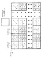
- FIG. 1 is an explanatory diagram of the ITU-T H.264 system that is an international video coding standard.
- a moving image is obtained by dividing an input frame 100 into a plurality of blocks and encoding in block units or a plurality of block units.
- FIG. 1 shows an example of block division in H.264.
- ITU-T H.264 which is an international video coding standard
- an image frame 100 is divided into macroblocks 103 each composed of 16 ⁇ 16 pixels.
- one of 4x4 and 8x8 is selected as orthogonal transform.
- the macro block 103 is further divided into 4 ⁇ 4 blocks (102) or 8 ⁇ 8 blocks (101), and encoding is performed using this block as an encoding unit.
- FIG. 2 shows an image encoding apparatus that divides an image into a plurality of blocks and encodes the blocks.
- the coding block is 4x4 or 8x8.
- an encoded block predicted image that is a predicted image having high correlation with the encoded block is generated.
- ITU-T H.264 there are an inter prediction image generation unit, an intra prediction image generation unit, and the like.
- the inter prediction image generation unit selects a region similar to the encoded block from the decoded images decoded in the past, and outputs the selected region as an encoded block predicted image.
- the intra-predicted image generation unit generates an image similar to the encoded block from the local decoded image of the peripheral block that has already been encoded of the current encoded image by extrapolation prediction, and outputs the image as an encoded block predicted image.
- both the inter prediction image generation unit and the intra prediction image generation unit are collectively referred to as an encoded block prediction image generation unit 200.
- the side information encoding unit 209 uses the entropy code for side information such as motion vector information indicating the relative positions of the encoding target block and the decoded image block and the intra prediction mode used in the inter prediction image generating unit. And superimposed on the bitstream.
- entropy coding is a technique for optimally compressing data using the appearance frequency of data.
- the prediction error image generation unit 201 calculates a difference between the encoded block and the encoded block predicted image to generate a prediction error image. Then, the transform unit 202 transforms the prediction error image into frequency coefficients using frequency transform such as discrete cosine transform and Hadamard transform.
- the quantization unit 203 quantizes the frequency coefficient to generate a quantized coefficient.
- quantization is realized by dividing a frequency coefficient by an appropriate quantizer and converting it into an integer and outputting the value as a quantization coefficient.
- the quantizer is switched for each frequency component position of the coefficient in MPEG-2 which is another international video coding standard and H.264 described above.
- the quantization coefficient is inversely quantized to generate a reproduction frequency coefficient.
- inverse quantization is realized by a quantizer used in the quantization unit 203 multiplying the quantization coefficient.
- the inverse transform unit 205 applies a reverse frequency transform corresponding to the frequency transform used in the transform unit to the playback prediction error image, thereby generating a playback prediction error image.
- the local decoded image generation unit 206 adds the encoded block prediction image and the reproduction prediction error image to generate a local decoded image.
- This local decoded image is stored in the decoded image storage unit 208, used for generating an inter predicted image in the subsequent frames, and also used for generating an intra predicted image of an encoding target frame. Then, the quantized coefficient is entropy encoded by the quantized coefficient encoding unit 207, and encoded block entropy encoded data is generated for each encoded block.
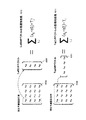
- FIG. 3 is an operation explanatory diagram of the conversion unit 202 of FIG.
- 301 shows the basis of Hadamard orthogonal transform. This conversion converts a four-point image into a four-point frequency.
- the values of the coefficients of the base pixels 0 to 3 having the frequency 0 are 0.5, 0.5, 0.5, and 0.5.
- the coefficient values of the base pixels 0 to 3 of frequency 1 are 0.5, 0.5, -0.5, and -0.5.
- the coefficient values of the pixels 0 to 3 are defined as 301.
- the frequency conversion of the prediction error image of 4x4 block can be realized by converting the vertical and horizontal directions by Hadamard orthogonal transform, for example.
- the frequency conversion in the vertical direction can be realized by expressing a 4 ⁇ 4 conversion target image in a matrix and multiplying this image by a Hadamard orthogonal transformation matrix from the left.
- the horizontal transformation can be realized by multiplying the result obtained by transposing a Hadamard orthogonal transformation matrix from the right.
- a frequency coefficient can be obtained for a prediction error image having a size of 4 ⁇ 4 blocks.
- FIG. 4 is an explanatory diagram of the processing operation of the encoding device shown in FIG. 2, and mainly shows changes in data values in the example of each pixel of the 4 ⁇ 4 block, taking the processing of 4 ⁇ 4 block conversion as an example.
- the Hadamard transform of FIG. 3 is used as the transform unit.
- the encoding target block 451 corresponds to one of the 16 blocks constituting the 4 ⁇ 4 block 102 in FIG. 1 and includes 16 pixels.
- the pixel value of the encoding target block prediction image block 450 with respect to the pixel value of the encoding target block (corresponding to the encoding block in FIG. 2) 451, for example, from the previous frame in time or from spatially adjacent images The difference between these pixel values is calculated by the prediction error image generation unit, and the pixel value of the prediction error image block 452 is generated.
- the pixel value is a value indicating the gradation of each pixel.
- the pixel value of the prediction error image block 452 of this 4 ⁇ 4 block is converted to a frequency by the Hadamard transform base of FIG. 3, and the value of the frequency coefficient block 453 is obtained.
- the frequency coefficient represents a horizontal frequency component in the horizontal direction, a vertical frequency component in the vertical direction, a low frequency of the horizontal / vertical component on the left and top, and a high frequency of the horizontal and vertical components on the right and bottom.
- the value of the frequency coefficient block 453 is quantized by the quantization unit.
- quantization is performed by dividing a frequency coefficient by a constant called a quantizer.
- the quantization method is calculated by the following equation, for example, where each coefficient is f, the quantizer is Q, and the quantization coefficient is C.
- sign (x) is a function that returns 1 if x is positive and -1 if negative.
- int (x) is a function that rounds off the decimal part of x to make it an integer
- abs (x) is a function that returns the absolute value of x.
- the quantizer is 3. Therefore, the value of the frequency coefficient block 453 of the DC component is ⁇ 7.25. And converted to a value of ⁇ 2 as a quantization coefficient. Other frequency coefficients are similarly quantized, and the value of the quantized coefficient block 454 is obtained.
- the quantized coefficient is converted into the value of the encoded block entropy encoded data block 458 by the quantized coefficient encoding unit.
- This quantization coefficient is further inversely quantized by the inverse quantization unit.
- the inverse quantization method is calculated, for example, by multiplying the inverse quantization coefficient by the inverse quantizer used in the quantization. That is, if the quantization coefficient is C, the quantizer is Q, and the reproduction frequency coefficient is f ′, It is represented by According to this equation, for example, the value of the DC component quantization coefficient block 454 is -2, so And converted to a value of -6 as a reproduction frequency coefficient. The other frequency coefficients are processed in the same manner, and the value of the reproduction frequency coefficient block 455 is obtained.
- the inverse conversion unit inversely transforms the reproduction frequency coefficient, and the pixel value of the reproduction prediction error image block 456 is generated.
- This reproduced prediction error image is added to the pixel value of the predicted image block 450 of the encoding target block by the local decoded image generation unit, and the pixel value of the local decoded image block 457 is generated.
- Each pixel value of the reproduction prediction error image block 456 is slightly different from each pixel value of the prediction error image block 452.
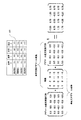
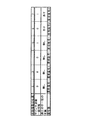
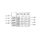
- FIG. 6 shows an example in which the value of the quantization coefficient block 454 of FIG. 4 is zigzag scanned and converted into non-zero effective coefficient information.
- Effective coefficient information which is a non-zero coefficient, is extracted, and position information in a zigzag scan, an absolute value of the effective coefficient, and sign information representing the sign of the effective coefficient are extracted from each effective coefficient.
- 0 is assigned as sign information when the quantization coefficient is positive, and 1 is assigned when it is negative.
- the first effective coefficient number in the zigzag scan order is 1
- the effective coefficient position information is 1
- the effective coefficient absolute value information is 2
- the effective coefficient sign information is 1.
- the effective coefficient of the second number has effective coefficient position information of 2, effective coefficient absolute value information of 3, and effective coefficient sign information of 0.
- the information in the table of FIG. 6 is obtained by sequentially converting in the same manner.
- FIG. 7 is a detailed configuration diagram of the quantized coefficient encoding unit 207 in FIG. 2 based on the above description.
- quantized coefficients are input to the quantized coefficient coding unit 207 in units of blocks.
- the quantized coefficient is decomposed by the effective coefficient information generation unit 720 into the effective coefficient position information, the effective coefficient absolute value information, and the effective coefficient sign information representing the positive / negative of the effective coefficient described with reference to FIG.
- an optimal entropy code is assigned by the effective coefficient position information encoding unit 721, and the effective coefficient position code is It is encoded efficiently.
- the effective coefficient absolute value information encoding unit 722 uses a bias that tends to generate a larger value as it is closer to the DC component and conversely tends to be smaller as it is closer to the high frequency.
- An optimal entropy code is assigned and is efficiently encoded as an effective coefficient absolute value code. For example, in the case of H.264 arithmetic coding (CABAC) mode, both the effective coefficient position information and the effective coefficient absolute value information reflect that a larger coefficient is more likely to appear at lower frequencies and a smaller coefficient at higher frequencies.
- CABAC H.264 arithmetic coding
- the optimal probability table is assigned to the arithmetic code in accordance with the position of the coefficient zigzag scan, thereby realizing highly efficient encoding.
- the effective coefficient sign information which is the sign of the coefficient
- positive and negative symbols are generated with the same probability of 0.5. Therefore, even if any entropy code is assigned, it cannot be efficiently encoded. For this reason, all the video coding standards such as ITU-T H.261 / H.263 / H.264, ISO / IEC MPEG-1, MPEG-2, MPEG-4 1-bit information is used and is output from the effective coefficient sign information encoding unit 723 as an effective coefficient sign code.
- the effective coefficient position code, the effective coefficient absolute value code, and the effective coefficient sign code are combined and output as encoded block entropy encoded data.
- FIG. 8 is a diagram showing the configuration of the image decoding apparatus corresponding to FIG.
- the quantized coefficient decoding unit 807 performs inverse entropy coding from the encoded block entropy coded data to decode the quantized coefficients, and then, similarly to the encoder, the inverse quantization unit 804 performs inverse quantization and inverse transform unit 805.
- a reverse prediction error image is generated by performing inverse transform in step (b).
- the encoded block predicted image generation unit 800 generates an encoded block predicted image
- the decoded image generation unit 806 adds the encoded block predicted image and the reproduction prediction error image to generate a decoded image. Then, this decoded image is stored in the decoded image storage unit 808 and simultaneously output for display.
- the local decoding unit of the encoding apparatus and a part of the decoding apparatus perform exactly the same operation. Therefore, the inverse quantization unit 804, the inverse transform unit 805, the encoded block predicted image generation unit 800, the decoded image generation unit 806, and the decoded image storage unit 808 in the decoding device in FIG.
- the same operations as those of the conversion unit 204, the inverse conversion unit 205, the encoded block predicted image generation unit 200, the decoded image generation unit 206, and the decoded image storage unit 208 are performed.
- sign information representing the sign of an effective quantization coefficient
- one bit is generally used for each coefficient. Since this sign information occupies 10% or more of the information amount of all target images, it is indispensable to reduce the sign information in order to further improve the compression rate.
- the pixel that is in contact with the boundary pixel of the block to be encoded and the pixel to be encoded are similar in the image included in the already decoded block.
- the sign information is efficiently encoded by generating a prediction value of the effective coefficient sign information and encoding whether or not the prediction value and the actual sign information coincide with each other.
- the presence of quantization coefficients means that there is a difference between the original image and the predicted image, that is, the accuracy of the predicted image is poor.
- pixels that are spatially in contact with each other have similar values. Therefore, it is expected that the boundary pixel in contact with the encoded block in the encoding target block has a value close to the pixel in contact with the encoding target block in the encoded block. Therefore, the value of the boundary pixel of the original image of the encoding target block can be estimated from the pixels in the encoding block that are in contact with the encoding target block.
- the difference between the original image and the predicted image at the boundary pixel of the encoded block can also be estimated from the pixel in contact with the encoding target block in the encoded block and the predicted image.
- an estimated value of the difference in the boundary pixel is set as a boundary pixel prediction error estimated value.
- the boundary pixel value in the reproduction prediction error obtained by dequantizing and inversely converting the quantization coefficient corresponding to the encoding target block is close to the boundary pixel prediction error estimated value.
- the absolute value and the position (frequency) of the quantized coefficients are known, the set of sign information of each coefficient for which the boundary pixel prediction error estimated value and the boundary pixel predicted error estimated value are close are obtained. It will be limited. Therefore, the sign information of each coefficient for which the boundary pixel of the reproduction prediction error and the estimated value of the boundary pixel prediction error are closest is a good prediction value of the actual sign information of each coefficient. If a good prediction value can be obtained, sign information can be efficiently encoded.
- each of the following embodiments first, from a locally decoded image of a coded block that has been coded before coding a coded block that contacts the coded block, and a coded block predicted image that is a predicted value of the coded block.
- the estimation value of the prediction error of the boundary pixel in contact with the encoded block among the encoded blocks is obtained.
- the sign that generates the reproduction prediction error that is closest to the estimated value of this prediction error is used as a sign information prediction value of an effective coefficient.
- Entropy encoding information on whether or not the sign information predicted value of the effective coefficient matches the sign information of the actual effective coefficient to be encoded (match information) is generated as ⁇ match '' or ⁇ not match '' information.
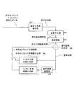
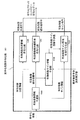
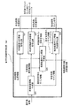
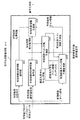
- FIG. 9 is a diagram illustrating an encoding apparatus based on the first embodiment.
- the first embodiment relates to a moving image encoding apparatus that divides an encoding target image into a plurality of block images and performs encoding for each encoding block.
- a quantized coefficient and a locally decoded image are generated from a prediction image and an encoding block that is an encoding target block. That is, first, the encoded block predicted image generation unit 900 generates an encoded block predicted image that is a predicted value of the encoded block by encoding. Next, a prediction error image generation unit 901 generates a prediction error image that is a difference between the encoded block and the encoded block prediction image. Subsequently, the conversion unit 902 converts the prediction error image into a frequency coefficient. Further, the quantization unit 903 quantizes the frequency coefficient to generate a quantization coefficient.
- the inverse quantization unit 904 inversely quantizes the quantization coefficient to generate a reproduction frequency coefficient.
- the inverse transformation unit 905 inversely transforms the reproduction frequency coefficient into a reproduction prediction error image.
- a local decoded image generation unit 906 generates a local decoded image from the reproduction prediction error image and the encoded block prediction image.
- boundary pixel predicted value generation unit 910 from the locally decoded images of a plurality of encoded blocks adjacent to the encoded block, the predicted value of the boundary pixel that contacts the encoded block in the encoded block A certain boundary pixel prediction value is generated.
- boundary pixel prediction error estimation unit 911 from the boundary pixel prediction value and the encoded block prediction image, the value of the boundary pixel and the boundary pixel prediction value of the encoded block prediction pixels with respect to the boundary pixel A boundary pixel prediction error estimated value is generated as the difference between the two.
- the quantized coefficient encoding unit 907 generates encoded block entropy encoded data by using the quantization coefficient and the boundary pixel prediction error estimated value (boundary pixel prediction error estimation information).
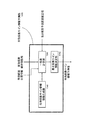
- FIG. 10 is a diagram illustrating a configuration of the quantized coefficient encoding unit 907 of FIG. 9 in the first embodiment.
- the effective coefficient information generating unit 1020 extracts a quantized coefficient whose value is not zero from the quantized coefficient as an effective coefficient, and effective coefficient position information indicating the frequency position of the effective coefficient.
- the effective coefficient absolute value information which is the absolute value of the effective coefficient, and the effective coefficient sign information representing the sign of the effective coefficient are generated. This operation is the same as that of the effective coefficient information generation unit 720 in FIG.
- the effective coefficient sign information prediction unit 1024 predicts sign information indicating whether the effective coefficient is positive or negative from the boundary pixel prediction error estimated value, the effective coefficient position information, and the effective coefficient absolute value information.
- An effective coefficient sign information prediction value that is a value is generated.
- the effective coefficients for generating the effective coefficient sign information prediction value may be all the effective coefficients of the coding block, or may be a part of the effective coefficients selected by a predetermined rule. .
- the configuration for generating the effective coefficient sign information prediction value for only some effective coefficients selected according to a predetermined rule will be described in detail in the fourth to sixth embodiments.
- the effective coefficient position information encoding unit 1021 generates the effective coefficient position code by entropy encoding the effective coefficient position information
- the effective coefficient absolute value encoding unit 1022 entropy encodes the effective coefficient absolute value information to Generate a value sign.
- the effective coefficient sign information prediction encoding unit 1023 entropy-encodes the sign prediction value match information indicating whether the effective coefficient sign information prediction value and the sign information of the effective coefficient match to generate an effective coefficient sign code. . Then, encoded block entropy encoded data is generated from the effective coefficient position code, the effective coefficient absolute value code, and the effective coefficient sign code.
- a highly accurate prediction value of effective coefficient sign information can be generated from effective coefficient position information, effective coefficient absolute value information, a predicted image, and a decoded image.
- the coincidence information as to whether or not the predicted value and the effective coefficient sign information coincide with each other will occupy a large number of “match” symbols.
- the information amount of the sign information is reduced. It is possible to reduce more.
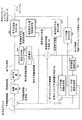
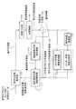
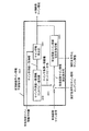
- FIG. 11 is a diagram showing a decoding device based on the second embodiment.
- the moving picture decoding apparatus according to the second embodiment divides an encoding target picture into a plurality of block pictures, and performs coding performed by the moving picture coding apparatus in FIG. 9 that performs coding for each coding block.
- the block entropy encoded data is decoded for each block.
- a decoded image is generated from encoded block entropy encoded data, as in the decoding apparatus of FIG. That is, the encoded block prediction image generation unit 1100 generates an encoded block prediction image that is a prediction value of the encoding block. Further, the quantization coefficient decoding unit 1107 decodes the quantization coefficient from the bit stream and the boundary pixel prediction error estimated value. Then, the quantization coefficient is inversely quantized by the inverse quantization unit 1104 to generate a reproduction frequency coefficient, and the inverse transformation unit 1105 inversely converts the reproduction frequency coefficient into a reproduction prediction error image, and the decoded image generation unit 1106 performs reproduction prediction. A decoded image is generated from the error image and the encoded block prediction image.
- the boundary pixel predicted value generation unit 1110 from the decoded images of a plurality of encoded blocks adjacent to the encoded block, the predicted value of the boundary pixel that contacts the encoded block in the encoded block A certain boundary pixel prediction value is generated.
- the boundary pixel prediction error estimation unit 1111 generates a boundary pixel prediction error estimation value for the boundary pixel from the boundary pixel prediction value and the encoded block prediction image, and sends it to the quantization coefficient decoding unit 1107.
- the quantization coefficient decoding unit 1007 generates a quantization coefficient from the encoded block entropy encoded data and the boundary pixel prediction error estimation value.
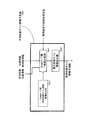
- FIG. 12 is a diagram illustrating a configuration of the quantization coefficient decoding unit 1007 of FIG. 11 in the second embodiment.
- the effective coefficient position information decoding unit 1231 extracts an effective coefficient position code from the encoded block entropy encoded data, and decodes effective coefficient position information that is the frequency position of the effective coefficient of the encoded block.
- the effective coefficient absolute value information decoding unit 1232 extracts the effective coefficient absolute value code from the encoded block entropy encoded data, and decodes the effective coefficient absolute value information that is the absolute value of the effective coefficient of the encoded block.
- the effective coefficient sign information prediction unit 1024 predicts sign information indicating whether the effective coefficient is positive or negative from the boundary pixel prediction error estimated value, the effective coefficient position information, and the effective coefficient absolute value information. An effective coefficient sign information prediction value that is a value is generated.
- the effective coefficient sign information prediction unit 1024 in FIG. 12 is exactly the same as the effective coefficient sign information prediction unit 1024 in FIG. 10 of the encoding device in the first embodiment.
- the effective coefficient sign effective coefficient Effective coefficient sign information which is sign information is decoded and output.
- the sign prediction value match information is “match”
- the sign information of the effective coefficient sign information prediction value is “same”
- the sign information indicates a sign opposite to the sign of the effective coefficient sign information prediction value. Is output.
- block quantization coefficients are generated from the effective coefficient absolute value information, effective coefficient position information, and effective coefficient sign information. Then, this quantized coefficient is processed by the same method as that of the decoding apparatus in FIG. 8 to generate a decoded image.
- the second embodiment it is possible to decode the encoded block entropy encoded data encoded in the first embodiment and further reducing the information amount of the sign information.
- FIG. 13 is a diagram illustrating an effective coefficient sign information prediction unit 1024 that is common to the first embodiment and the second embodiment.
- the effective coefficient sign information prediction value is obtained as follows. First, in the effective coefficient sign information candidate generation unit 1340, the effective coefficient sign information for each effective coefficient is positive or negative with respect to the coefficient given by the effective coefficient position information and the effective coefficient absolute value information in the coding block. A combination of a plurality of pieces of signature information to which these are temporarily assigned is generated. This is a valid coefficient sign information candidate. Since there are two types of sign information indicating the sign of each effective coefficient, positive and negative, for example, when generating effective coefficient sign information candidates for N effective coefficients, as a combination, a maximum of 2 to the Nth power There are street combinations.
- the degree of coincidence calculation unit 1341 calculates the degree of coincidence between each effective coefficient sign information candidate, the effective coefficient position information, and the reproduction prediction error signal obtained from the effective coefficient absolute value information and the boundary pixel prediction error estimated value. To do. Then, the maximum likelihood coefficient sign information determination unit 1342 outputs the effective coefficient sign information candidate having the highest degree of matching as the effective coefficient sign information prediction value. This effective coefficient sign information prediction value coincides with the effective coefficient sign information with a high probability. Therefore, by encoding the difference between the effective coefficient sign information and its predicted value, the probability of the symbol “matching” between them increases, and by performing optimal entropy encoding, information on the effective coefficient sign information The amount can be reduced.
- FIG. 14 is a diagram illustrating a third embodiment, which is another implementation of the effective coefficient sign information prediction unit 1024 (FIGS. 10 and 12) in the first and second embodiments.
- the effective coefficient sign information prediction value is obtained as follows. First, in the Gray code (gray code) effective coefficient sign information candidate generation unit 1440, effective coefficient sign information for each effective coefficient is obtained for the coefficient given by the effective coefficient position information and effective coefficient absolute value information in the coding block. A combination of a plurality of pieces of sign information tentatively assigned either positive or negative is generated so as to correspond to 0/1 of each bit position of the Gray code.
- the technique described in Patent Document 1 is referred to as a Gray code in accordance with a widely used name.
- the effective coefficients having different signs are identified between the immediately preceding effective coefficient sign information candidate and the effective coefficient sign information candidate to be evaluated. To do.
- the influence of the degree of coincidence on the cost calculation process is obtained from the change of the sign of the effective coefficient.
- the difference between the coincidence cost of the previous effective coefficient sign information candidate and the coincidence cost of the effective coefficient sign information candidate to be evaluated Ask for. Further, by adding this difference to the cost of the matching degree of the previous effective coefficient sign information candidate, the cost of matching degree of the effective coefficient sign information candidate to be evaluated is obtained.
- the maximum likelihood coefficient sign information determination unit 1442 outputs the effective coefficient sign information candidate having the highest degree of matching as an effective coefficient sign information prediction value. According to the third embodiment described above, without calculating the cost of matching every time, only the cost difference of the matching score is obtained from the effective coefficient sign information whose sign has changed, and this value is used as the matching score of the previous candidate. Therefore, the amount of calculation can be further reduced.
- the effective coefficient sign information prediction unit uses the prediction value of the sign information of the effective coefficient and encodes whether the prediction and the actual value match. Is generated.
- sign information of an effective coefficient with high prediction accuracy is generated, and as a result, the probability that the sign information matches the predicted value is increased.
- entropy codes can be encoded more efficiently when the probability of symbol occurrence is biased. By performing appropriate entropy coding, this coincidence information can be coded with an average of less than 1 bit per symbol. For this reason, it is possible to further reduce the amount of information of sign information by performing appropriate entropy coding on the sign information matching information.
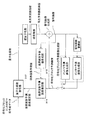
- FIG. 15 is a diagram illustrating an encoding apparatus based on the fourth embodiment.
- the fourth embodiment shown in FIG. 15 is based on the first embodiment shown in FIG. 9, and is based on a quantization coefficient encoding unit 1507, a boundary pixel prediction error estimation unit 1511, and a boundary pixel prediction value generation unit 1510. Is disclosed in more detail.
- the processing units 1507, 1511, and 1510 correspond to the processing units 907, 911, and 910 having the same names in FIG. In FIG. 15, each processing unit having the same name as in FIG. 9 executes the same process as in FIG.
- a block having the values of the encoding target block 451 and the encoding target block prediction image 450 shown in FIG. 4 is converted into a conversion unit, a quantization unit, an inverse quantization unit, and an inverse conversion equivalent to those in FIG.
- An example of encoding using a local decoding unit and a local decoding generation unit is shown. Since these arithmetic processes are equivalent to a general method, the quantization coefficient shown in FIG. 15 is also the same as the quantization coefficient 454 of FIG.
- the local decoded image in FIG. 15 is also the same as the local decoded image 457 in FIG.
- details of the boundary pixel prediction value generation unit 1510, the boundary pixel prediction error estimation unit 1511, and the quantization coefficient encoding unit 1507 will be described in the fourth embodiment.
- FIG. 16 is a diagram illustrating an example of a boundary pixel of an encoding target block 1661 (encoding block) having a size of 4 ⁇ 4 when the base size of orthogonal transformation such as H.264 is 4 ⁇ 4.
- encoding processing proceeds in units of blocks from the upper left to the lower right. For this reason, encoding of the left and upper blocks of the encoding block is completed before encoding of the encoding block.
- a block that has already been encoded at the time of encoding the encoded block is referred to as a coded block (1662).
- the pixels on the upper and left ends of the encoded block are in contact with the encoded block. Therefore, the upper and left end pixels in the encoding target block in FIG. 16 are defined as boundary pixels (1660).
- FIG. 17 is a diagram illustrating a processing example of the boundary pixel predicted value generation unit 1510 according to the fourth embodiment.
- the boundary pixel prediction value generation unit 1510 receives a local decoded image in the vicinity of the left, upper left, and upper boundaries of the encoded block, and generates a boundary pixel prediction value.
- the pixels of the encoded block of the locally decoded image in contact with the boundary pixel are the same as those in FIG. 16.
- the pixels that touch the left are L0 to L3
- the pixels that touch the top are U0 to U3
- the pixels that touch the top left are UL, with respect to the pixels of the input local decoded image.
- the boundary pixel prediction values at the boundary pixels of the coding block are assumed to be E0, E1, E2, E3, E4, E5, and E6 in order from the lower left to the upper right.
- the boundary pixel predicted values E0 to E6 are obtained from the pixels L0 to L3, U0 to L3, and UL of the locally decoded image of the encoded block near the boundary pixel by the following formula.
- E0 L3
- E1 L2
- E2 L1
- E3 (L0 + UL + U0)
- E4 U1
- these boundary pixel prediction values are output.
- the value of the nearest pixel is used as it is or averaged.
- the neighborhood of the prediction target pixel is also used. It is also possible to use a pixel prediction method or the like in general pixel adaptive DPCM encoding using a plurality of pixels for generating a boundary pixel prediction value.
- FIG. 18 is a diagram illustrating an implementation example of the boundary pixel prediction error estimation unit 1511 in the fourth embodiment.
- a boundary pixel prediction error estimation value is generated from the boundary pixel prediction value generated in FIG. 17 and the value of the encoding target block prediction image 450 in FIG.
- the boundary pixel prediction values E0 to E6 are boundary pixel prediction values of the boundary pixels of the encoded block corresponding to FIG.
- Pixels P0 to P6 are values of boundary pixels of the encoded block prediction image.
- Pixels D0 to D6 are boundary pixel prediction error estimation values.
- n is a number between 0 and 6
- Dn En-Pn
- the boundary pixel prediction error estimated value of each pixel is obtained. For example, since the value of the pixel E3 is 57 and the value of the pixel P3 is 55, the value of 2 is obtained by subtracting 55 from 57.
- FIG. 19 is a diagram illustrating an implementation example of the quantized coefficient coding unit 1507 in the fourth embodiment.
- this implementation example not all effective coefficients but coefficients that use the effective coefficient sign information prediction value are selected, a coefficient that is predictively encoded using the sign information prediction value, and a general 1-bit fixed-length code are used. An example of combining with existing coefficients will be described.
- the effective coefficient information generation unit 1920 extracts, as an effective coefficient, a quantization value whose value is not zero from the quantization coefficient, and effective coefficient position information representing the frequency position of the effective coefficient, Effective coefficient absolute value information, which is the absolute value of the effective coefficient, and effective coefficient sign information representing the sign of the effective coefficient are generated.
- Effective coefficient absolute value information which is the absolute value of the effective coefficient
- effective coefficient sign information representing the sign of the effective coefficient
- an effective coefficient for predictively encoding sign information using an effective coefficient sign information prediction value, and a fixed length An effective coefficient for encoding sign information is determined using encoding, and an index of an effective coefficient for encoding sign information using the latter fixed-length encoding (fixed-length encoded sign information index) is output.
- an effective coefficient sign information predicted value that is a predicted value of sign information indicating whether each coefficient is positive or negative is generated.
- the effective coefficient position information encoding unit 1921 generates effective coefficient position code by entropy encoding the effective coefficient position information, and the effective coefficient absolute value encoding unit 1922 performs entropy encoding on the effective coefficient absolute value information to Generate a value sign.
- the effective coefficient sign information prediction encoding unit 1923 encodes the effective coefficient sign information.
- the effective coefficient sign information indicated by the fixed-length encoded sign information index is encoded using fixed-length encoding.
- the effective coefficient sign information is generated by entropy-encoding the sign prediction value matching information indicating whether the effective coefficient sign information prediction value and the sign information of the effective coefficient match.
- the encoded block entropy encoded data is generated by combining the effective coefficient position code, the effective coefficient absolute value code, and the effective coefficient sign code.
- FIG. 20 is a diagram illustrating an implementation example of the effective coefficient sign information prediction unit 1924 according to the fourth embodiment.
- the effective coefficient sign information candidate generation unit 2040 the effective coefficient sign information for each effective coefficient is positive or negative with respect to the coefficient given by the effective coefficient position information and the effective coefficient absolute value information in the coding block. Generate multiple combinations that are assigned. This is a valid coefficient sign information candidate. Since sign information indicating the sign of each effective coefficient is two types, positive and negative, for example, when generating effective coefficient sign information candidates for N effective coefficients, a maximum of 2 to the Nth power is combined. There are street combinations.
- the matching degree calculation unit 2041 includes an effective coefficient rearranging unit 2070, a quantized coefficient provisional value generation unit 2071, a boundary pixel prediction error provisional value generation unit 2722, and a prediction error matching degree calculation unit 2073.
- the effective coefficient rearrangement unit 2070 rearranges the effective coefficients using the effective coefficient position information and the effective coefficient absolute value information of the encoded block. This rearrangement is performed from an effective coefficient expected to have a high accuracy of the generated effective coefficient sign information prediction value to a lower effective coefficient. When the number of effective coefficients is large, a coefficient to be encoded using a prediction value by an effective coefficient sign information prediction value is selected from those having high accuracy as necessary.
- the provisional value of the quantization coefficient is applied to the effective coefficient reordered by the effective coefficient rearranging unit 2070 and applied to each effective coefficient sign information candidate code in the quantization coefficient provisional value generation unit 2071. Is generated for each effective coefficient sign information candidate.
- the boundary pixel prediction miscalculation provisional value generation unit 2072 dequantizes and inversely transforms the generated quantized coefficient provisional value to select only the boundary pixel, so that the boundary pixel that is the provisional error prediction value of the boundary pixel A prediction error provisional value is generated for each effective coefficient sign information candidate.
- the prediction error coincidence calculation unit 2073 calculates the degree of coincidence between the field pixel prediction error provisional value generated for each valid coefficient sign information candidate and the boundary pixel prediction error estimated value.
- the maximum likelihood coefficient sign information determination unit 2042 outputs the effective coefficient sign information candidate having the highest degree of coincidence generated by the prediction error coincidence calculation unit as an effective coefficient sign information prediction value. Since the difference between the effective coefficient sign information prediction value and the effective coefficient sign information generated from the quantization coefficient of the frequency coefficient of the prediction error image of the encoding target block of the original image is small, as shown in FIG. By encoding the difference by the effective coefficient sign information predictive encoding unit 1923, an effective coefficient sign code optimally entropy-coded can be obtained.
- FIG. 21 is a diagram illustrating a processing example of the effective coefficient rearranging unit 2070 in the fourth embodiment.
- the input to the effective coefficient rearranging unit 2070 is the same as the effective coefficient position information and effective coefficient absolute value information of the coding block in FIG.
- the provisional value of the boundary pixel prediction error is obtained by multiplying the base of the orthogonal transform corresponding to the effective coefficient by a value obtained by multiplying the inverse quantized value for all the effective coefficients of the coding block, and accumulating this. Is required. Therefore, the larger the effective coefficient absolute value, the greater the influence on the boundary pixel prediction error provisional value.
- a different quantizer is used for each effective coefficient position corresponding to the effective coefficient in H.264 or the like, so that the effective coefficient absolute value is inverted instead of the effective coefficient absolute value. It is also possible to determine the priority based on the quantized value.
- the effective coefficients are rearranged in the rearrangement process 2110 according to the above rules, and rearranged effective coefficient position information and effective coefficient absolute value information 2101 are obtained.
- the fourth embodiment in the selection process 2111, the first six coefficients are selected from the rearranged coefficients, and the coefficients are encoded using the effective coefficient sign information prediction value. decide. For the remaining two coefficients having the effective coefficient position information of 5 and 4, the effective coefficient position information of “5” and “4” is output as the fixed-length encoded sign information index 2103.
- These coefficients are encoded using a general method, for example, a fixed length code of 1 bit per code.
- the six effective coefficients 2102 are output as the coefficients that are rearranged and use the effective coefficient sign information prediction value.
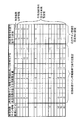
- FIG. 22 is a diagram illustrating a processing example of the effective coefficient sign information candidate generation unit 2040 in the fourth embodiment.
- This figure shows an example of generating effective coefficient sign information candidates for the selected six effective coefficients.
- the effective coefficient is described on the figure using the position information of each effective coefficient as an index. Since there are six coefficients, there are 64 combinations of positive and negative sign information for the six coefficients, which is 2 to the sixth power. Therefore, first, an index of effective coefficient sign information candidates is prepared as 0 to 63, and a binary notation of this index is defined as a sign information candidate for each effective coefficient.
- the sign information candidate of each effective coefficient is defined as positive if the value is 0 and negative if it is 1.
- the effective coefficient sign information candidate index 2200 associated with the generated 64 effective coefficient sign information candidates 2201 is output to the quantized coefficient provisional value generation unit 2071.
- the index of the effective coefficient sign information candidate indicating the correct code is 8.
- FIG. 23 is a diagram illustrating a processing example of the quantization coefficient provisional value generation unit 2071 according to the fourth embodiment.
- the effective coefficient absolute value information corresponding to each effective coefficient position information is quantized by setting each code of effective coefficient sign information candidate 2201 of FIG. 22 corresponding to effective coefficient sign information candidate index 2200 as a coefficient.
- a process for generating a coefficient provisional value is described. For example, for the effective coefficient sign information candidate index 0, a positive coefficient is generated as a provisional value of quantized coefficients. Further, when the candidate index is 13, the coefficients of the effective coefficient position information 2, 3, and 9 are set as positive, and when the effective coefficient position information is 1, 10, and 7, the negative sign is set.
- FIG. 24 is a diagram illustrating a processing example of the boundary pixel prediction error provisional value generation unit 2072, the prediction error coincidence calculation unit 2073, and the maximum likelihood coefficient sign information determination unit 2042 in the fourth embodiment.
- the boundary pixel prediction error provisional value generation unit 2072 performs inverse quantization equivalent to that used in normal encoding for the quantization coefficient provisional values 2400a to 2400n generated for each effective coefficient sign information candidate. Apply reverse transformation.
- coefficients having original codes are set for coefficients that do not use the effective coefficient sign information prediction values of the effective coefficient position information 5 and 4 shown in FIG.
- boundary pixels are selected from the inversely converted values, and boundary pixel prediction error provisional values 2401a to 2401n are generated.
- the reason why the calculation is not equivalent but equivalent is that this calculation does not necessarily require high accuracy, and an operation with reduced calculation accuracy may be substituted to reduce the amount of calculation.
- the boundary pixel prediction error provisional values 2401a to 2401n, the boundary pixel prediction error estimated value generated by the boundary pixel prediction error estimation unit 1511, and Differences 2402a to 2402n are generated, and the cost values 2403a to 2403n obtained by squaring and adding these values squared are used as the degree of coincidence.
- the maximum likelihood coefficient sign information determination unit 2042 totals the degree of coincidence (square error cost) 2403a to 2403n for each effective coefficient sign information candidate and determines the effective coefficient corresponding to the effective coefficient sign information candidate index that gives the minimum cost.
- Coefficient sign information is output as an effective coefficient sign information prediction value. That is, the absolute value of the effective coefficient is reduced from the effective coefficient (nonzero element in the quantized coefficient block) of the frequency coefficient corresponding to the difference (prediction error) between the encoding target block and the encoded block prediction image.
- an effective coefficient sign information candidate whose effective coefficient sign information candidate index is 13 is output as an effective coefficient sign information prediction value.
- FIG. 25 is a diagram illustrating the effective coefficient sign information prediction encoding unit 1923 according to the fourth embodiment.
- the effective coefficient sign information that does not use the effective coefficient sign information prediction value that is, encodes sign information with a fixed length
- the switch 2501 based on the fixed-length encoded sign information index.
- the effective coefficient sign information is encoded by the effective coefficient sign information fixed length encoding unit 2503 with a fixed length using information of 1 bit per coefficient. For example, a 1-bit code of “0” is assigned to positive sign information and a “1” is assigned to negative sign information. In the case of the coefficients shown in FIG.
- the sign predicted value match information generation unit 2500 uses the effective coefficient sign information predicted value and the effective coefficient sign. Generates match information indicating whether the information matches.
- the effective coefficient sign information entropy coding unit 2502 entropy codes the matching information.
- FIG. 26 is a diagram for explaining the processing of the sign predicted value match information generation unit 2500 in the fourth embodiment.
- the upper part represents the position information of the effective coefficient
- the lower part represents the effective coefficient sign information, the effective coefficient sign information prediction value, and the sign prediction value match information corresponding to the effective coefficient position information.
- each effective coefficient it is determined for each effective coefficient whether the effective coefficient sign information 2601 of the six effective coefficients selected matches the effective coefficient sign information prediction value 2600.
- “1” is output as sign predicted value match information 2602. Since the effective coefficients are arranged in descending order of the expected prediction accuracy of the effective coefficient sign information prediction value 2600, the first order coefficient matches both, and the latter order coefficient decreases. For this reason, it is expected that the probability of “match” symbols is higher in the first half.
- “match” is 0 and “mismatch” is 1.
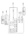
- FIG. 27 is a diagram illustrating an effective coefficient sign information entropy encoding unit 2502 according to the fourth embodiment.
- the order is rearranged in absolute value order, and the sign information predicted value match information is encoded in the rearranged order in comparison with the encoding of the sign predicted value match information 2602 of the selected coefficient. That is, in the fourth embodiment, as shown in the sine predicted value match information in FIG. 26, 0, 0, 0, which is the sine predicted value match information of the coefficient positions 2, 3, 1, 10, 8, and 7.
- Encoding is performed in the order of 1, 0, 1, and a sine prediction value match information entropy code 2700 is generated.
- an arithmetic code 1 (2701) and an arithmetic code 2 (2702) are prepared.
- the arithmetic code 1 is an optimal code when the probability (match probability) of the matching symbol “0” is 0.8 and the probability of the non-matching symbol “1” is 0.2
- the arithmetic code 2 is the matching symbol “0”. Is the optimal arithmetic coding method when the probability (match probability) is 0.6 and the probability of the mismatch symbol “1” is 0.4.
- the arithmetic unit 1 switches between the arithmetic code 1 and the arithmetic code 2 in a determination unit 2703 that determines whether or not there is a non-matching symbol before encoding the sign prediction value match information.
- arithmetic code a general arithmetic code described in Non-Patent Document 2 can be used.
- an arithmetic coding method in which the probability table is updated every time a symbol is coded such as CABAC used in the moving picture coding international standard ITU-T H.264.
- the first effective coefficient 2 is encoded in order with arithmetic code 1. As long as the previous sign prediction value match information is “match”, that is, “0”, encoding is performed with arithmetic code 1. When the sign prediction value match information of the effective coefficient immediately before becomes “mismatch”, that is, “1”, all sign prediction value match information after the next is encoded using the arithmetic code 2. In the case of FIG. 28, the arithmetic code 1 is used for the first effective coefficient (the position of the effective coefficient is 2).
- the encoder uses the arithmetic code 1. Since the sign prediction value match information with the effective coefficient position of 10 encoded as the position of the effective coefficient immediately before the code of 8 is “mismatch” “1”, the sign information with the effective coefficient positions of 8 and 9 is used. The predicted value match information is encoded with the arithmetic code 2.
- the sine prediction value match information is “mismatch”, that is, “matches” with “1” after the prediction coefficient whose prediction is off. ", That is, based on the fact that the probability of occurrence of" 0 "tends to be equal.
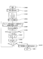
- step S2903 it is checked whether the variable State is 1 or not.
- the i-th sign predicted value match information S [i] is encoded with the arithmetic code 1 in step S2904.
- step S2905 it is determined whether S [i] is “match” or “not match”. Only in the case of “mismatch”, the state variable State is set to 2 in step S2907.
- step S2903 If it is determined in step S2903 that the State is not 1, that is, 2, the i-th sign predicted value match information S [i] is encoded with the arithmetic code 2 in step S2906.
- step S2903 it is determined whether the counter i is larger than n. If the counter i is larger, the encoding is terminated. Otherwise, the process proceeds to step S2903.
- FIG. 30 is a diagram for explaining an embodiment in which encoded block entropy encoded data 3000 is generated by combining effective coefficient position code 3001, effective coefficient absolute value code 3002, and effective coefficient sign code 3005.
- the effective coefficient sign information prediction unit 1924 in FIG. 19 generates a fixed-length encoding index from effective coefficient position information and effective coefficient absolute value information, and then generates fixed-length encoding sign information, An effective coefficient sign information predicted value is generated from the effective coefficient position information, the effective coefficient absolute value information, and the boundary pixel prediction error estimated value. For this reason, in order to generate the fixed-length coding index and the effective coefficient sign information prediction value on the decoding device side as well, there is a restriction on the code order.
- the effective coefficient position code 3001 and the effective coefficient absolute value code 3002 exist before the effective coefficient sign code 3005 so that the fixed-length coding index and the effective coefficient sign information prediction value can be generated on the decoding device side. It only has to be.
- the encoded block entropy encoded data according to the fourth embodiment includes effective coefficient position information 3001 having effective coefficient position information and effective coefficient absolute value information values as shown in FIG. 30, effective coefficients. It consists of an absolute value code 3002, sign information “1” and “0” of effective coefficient positions 5 and 4 encoded with a fixed length code 3003, and a sign prediction value match information entropy code 3005. Further, the sine prediction value match information entropy code 3005 includes match information “0”, “0”, “0”, “1” of the effective coefficient positions 2, 3, 1, and 10 encoded by the arithmetic code 1. It consists of coincidence information “0”, “1” of effective coefficient positions 8 and 7 encoded with arithmetic code 2.
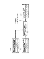
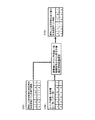
- FIG. 31 is a diagram showing a decoding device based on the fifth embodiment.
- the fifth embodiment shown in FIG. 31 includes a quantization coefficient decoding unit 3107, a boundary pixel prediction error estimation unit 3111, and a boundary pixel prediction value generation unit 3110 based on the second embodiment shown in FIG. Further details will be disclosed.
- the processing units 3107, 3111, and 3110 correspond to the processing units 1107, 1111, and 1110 having the same names in FIG. In FIG. 31, each processing unit having the same name as in FIG. 11 executes the same processing as in FIG.
- the decoding apparatus of the fifth embodiment decodes the encoded block entropy encoded data 3000 of FIG. 30 generated by the encoding apparatus of the fourth embodiment of FIG. This is equivalent to the block described in the fourth embodiment.
- the inverse quantization unit, the inverse transform unit, the decoded image generation unit, and the encoded block predicted image generation unit are respectively the inverse quantization unit and the inverse transform unit described in the fourth embodiment of FIG.
- the local decoded image generation unit, the encoded block prediction image generation unit, the boundary pixel prediction value generation unit, and the boundary pixel prediction error estimation unit are the same. Therefore, the example of operation
- movement of each part is also equivalent to 4th Embodiment.
- the locally decoded image described in the fourth embodiment is replaced with a decoded image in the fifth embodiment. This is because each part described above is called a so-called local decoder, and is the same in the encoding device and the decoding device.
- the configurations and operation examples of the boundary pixel prediction value generation unit 3110 and the boundary pixel prediction error estimation unit 3111 are the same as those in the fourth embodiment.
- a general decoding device in FIG. 11 and a quantized coefficient decoding unit 3107 different from the fourth embodiment in FIG. 15 will be described.
- FIG. 32 is a diagram illustrating a quantized coefficient decoding unit 3107 according to the fifth embodiment.
- the operation will be described through a process of decoding the encoded block entropy encoded data 3000 of FIG. 30 according to the fourth embodiment.
- effective coefficient position information decoding section 3231 takes out effective coefficient position code 3001 from encoded block entropy encoded data 3000 and decodes effective coefficient position information that is the frequency position of the effective coefficient of the encoded block. As a result, from FIG. 30, as the effective coefficient position, 1, 2, 3, 4, 5, 7, 9, 10 Get. At the same time, the number of effective coefficients (8) is also acquired.
- effective coefficient absolute value information decoding section 3232 extracts effective coefficient absolute value code 3002 from encoded block entropy encoded data 3000 and decodes effective coefficient absolute value information that is the absolute value of the effective coefficient of the encoded block. .
- effective coefficient absolute value information 2,3,2,1,1,1,1,1 Get.
- the effective coefficient sign information prediction unit 1924 first generates a fixed-length encoded sign information index.
- an effective coefficient sign information prediction unit 1924 that is exactly the same as in the fourth embodiment is used. This is because it is necessary to generate exactly the same effective coefficient sign information prediction value in the encoding device and the decoding device. Therefore, description of the operation of the effective coefficient sign information prediction unit 1924 is omitted.
- the effective coefficient sign information prediction unit 1924 receives the effective coefficient position information and the effective coefficient absolute value information, and has 5, as the fixed-length encoded sign information index. 4 Is output.
- FIG. 33 is a diagram illustrating the effective coefficient sign information prediction decoding unit 3233 according to the fifth embodiment.
- the effective coefficient sign information fixed length code 3003 is selected by the switch 3301 according to the fixed length code sign information index, and is decoded by the effective coefficient sign information fixed length decoding unit 3303.
- the sign predicted value match information entropy code 3004 is selected by the switch 3301 according to the fixed-length code sign information index. Then, in the sign prediction value match information entropy decoding unit 3300, the sign prediction value match information entropy code 3004 is decoded, and as the sign prediction value match information, 0, 0, 0, 1, 0, 1 Get.
- the sign information reproduction unit 3302 compares the effective coefficient sign information predicted value with the coincidence information to generate valid coefficient sign information “0, 0, 0, 1, 0, 1”. As a result, the effective coefficient sign information 3703 corresponding to FIG. 6 is decoded.
- the effective coefficient sign information prediction value 3701 “0, 0.1, 1, 0, 1” is generated by the effective coefficient sign information prediction unit 1924 shown in FIG.
- the effective coefficient sine information prediction unit 1924 obtains the first value from the fixed-length encoded sine information obtained by the effective coefficient sine information fixed-length decoding unit 3303 and the boundary pixel prediction error estimation value generated by the boundary pixel prediction error estimation unit 3111.
- the effective coefficient sign information prediction value is generated by the same method as described with reference to FIGS.
- the boundary pixel prediction error estimation value input to the effective coefficient sign information prediction unit is the same method as that described in the fourth embodiment with reference to FIGS. 16 to 18 in the boundary pixel prediction error estimation unit 3111. Is generated.
- FIG. 34 is a diagram showing a sine prediction value match information entropy decoding unit 3300 in the fifth embodiment, and corresponds to the sine prediction value match information entropy encoding unit 3502 in the fourth embodiment of FIG. .
- the sine prediction value match information entropy encoding unit includes arithmetic decoding 1 (3401) and arithmetic decoding 2 (3402) corresponding to arithmetic code 1 (2701) and arithmetic code 2 (2072), respectively.
- Arithmetic decoding 1 is designed to be most efficient when the probability of a “match” symbol is 0.8
- arithmetic decoding 2 is designed to be most efficient when the probability of a “match” symbol is 0.6. is there.
- the selection method of arithmetic decoding 1 and arithmetic decoding 2 is the same as that of the sign prediction value match information entropy encoding unit 2502 in the fourth embodiment. This operation will be described with reference to FIG.
- the first effective coefficient position is decoded in order from the arithmetic coefficient 1 to obtain sign prediction value match information.
- the sign prediction value match information decoded immediately before is “match”, that is, “0”
- decoding is performed by arithmetic decoding 1.
- the sign prediction value match information of the effective coefficient decoded immediately before becomes “mismatch”, that is, “1”, all the sign prediction value match information entropy codes after that use arithmetic decoding 2.
- arithmetic decoding 1 is used for the first sign predicted value match information entropy code (effective coefficient position is 2). Further, since the sign prediction value match information of the effective coefficient decoded immediately before is “match” “0” until the positions of the effective coefficients are 3, 1, and 10, the decoder uses arithmetic decoding 1. Since the sign prediction value match information with an effective coefficient position of 10 decoded immediately before the sign prediction value match information entropy code with an effective coefficient position of 8 is “mismatch” “1”, the position of the effective coefficient is 8 And 9 sign prediction value match information entropy codes are encoded by arithmetic decoding 2.
- FIG. 36 is a flowchart for describing arithmetic decoding selection processing used for decoding of sign prediction value match information.
- step S3601 n sign predicted value match information entropy codes are input.
- n storage areas S [i] for sign prediction value match information are prepared.
- the counter i is initialized to 1.
- step S3603 check if the variable State is 1. In the case of 1, the i-th sign predicted value match information entropy code is decoded by arithmetic decoding 1 in step S3604, and the obtained sign predicted value match information is stored in S [i]. In step S3605, it is determined whether the decrypted S [i] is “match” or “mismatch”. Only in the case of “mismatch”, the state variable State is set to 2 in step S3607.
- step S3603 If it is determined in step S3603 that the State is not 1, that is, 2 in step S3606, the i-th sign predicted value match information entropy code is decoded by arithmetic decoding 2 in step S3606, and the obtained sign predicted value match information is obtained. Store in S [i].
- Step S3609 it is determined whether or not the counter i is greater than n. If the counter i is larger, the decoding process is terminated. Otherwise, the process proceeds to step S3603.
- FIG. 37 is a diagram for explaining the processing of the sign information reproduction unit 3302 in the fifth embodiment.
- the upper part represents the position information of the effective coefficient
- the lower part represents the effective coefficient sign information, the effective coefficient sign information prediction value, and the sign prediction value match information corresponding to the effective coefficient position information.
- the sine prediction value match information 3702 has a value of 0 when the effective coefficient sine information prediction value and the sine information match, and 1 when they do not match. Therefore, the sign information reproduction unit 3302 calculates the effective coefficient sign information predicted value 3701 and the sign predicted value match information 3702 for each sign information of each coefficient by exclusive OR calculation, thereby obtaining sign information 3703 for each effective coefficient. Is played.
- the effective coefficient sign information predictive decoding unit 3333 in FIG. 32 collects the effective coefficient sign information generated by the effective coefficient sign information fixed length decoding unit 3303 and the sign information reproduction unit 3302 to obtain the effective coefficient sign of the coding block. Output as information.
- the quantization coefficient is input to the inverse quantization unit in FIG. 31, and the image is decoded by a method similar to a general decoding device.
- the encoded block entropy data encoded efficiently in the fourth embodiment can be correctly decoded.
- the sixth embodiment is another embodiment of the effective coefficient sign information prediction unit 1924 (FIGS. 19 and 32) common to the fourth and fifth embodiments.
- the four-point Hadamard transform is one of the most basic orthogonal transforms.
- FIG. 38 is a diagram for explaining orthogonal basis vectors constituting the 4-point Hadamard transform according to the sixth embodiment.
- a frequency 0 basis vector is defined as T 0 (3800)
- a frequency 1 basis vector is defined as T 1 (3801)
- a frequency 2 basis vector is defined as T 2 (3802)
- a frequency 3 basis vector is defined as T 3 (3803).
- This four-point Hadamard transform can be expressed using the orthogonal basis vectors that are the four horizontal vectors.
- the coefficient corresponding to pixel 0 in the base vector T 0 (3800) at frequency 0 is t0 0 (3850), and the base vector T 1 (3801) at frequency 1 is The coefficient corresponding to pixel 0 is t0 1 (3851), the coefficient corresponding to pixel 0 is t0 2 (3852) in the frequency 2 basis vector T 2 (3802), and the frequency 3 basis vector T 3 (3803)
- the coefficient corresponding to pixel 0 is defined as t0 3 (3853).
- FIG. 39 shows the relationship between the reproduction frequency coefficient matrix 3955 and the reproduction prediction error matrix 3956 in the two-dimensional four-point Hadamard transform performed by the inverse transformation unit 905 in FIG.
- a weighted cumulative sum expression 3920 by each frequency coefficient 3911 of the reproduction frequency coefficient matrix 3955 of the dimensional orthogonal base 3922 will be described.
- the reproduction prediction error matrix 3956 that is the output of the inverse transform unit 905 in FIG. 9 generally includes a Hadamard orthogonal transformation matrix 3910 from the right and a Hadamard orthogonal transformation matrix 3911 from the left with respect to the reproduction frequency coefficient matrix 3955. It is calculated by multiplying.
- the Hadamard orthogonal transformation matrix 3910 is derived from the bases T 0 (3800), T 1 (3801), T 2 (3802), and T 3 (3803) of the frequencies 0 to 3 of the Hadamard transform described in FIG. Composed.
- the transposed matrix 3911 of the Hadamard transform has T 0 t (3900), T 1 t (3901), T 2 t (3902), T 2 t (3902), transposed bases of the frequency 0 to the frequency 3 of the Hadamard transform described in FIG. It consists of each vertical vector of T 3 t (3903).
- the reproduction prediction error matrix 3956 is expressed as a cumulative sum representation of the 4-point Hadamard transform from the Hadamard transform bases T 0 to T 4 and their transposed vectors T 0 t to T 4 t and the coefficients of the reproduction frequency coefficients. It can be expressed as Here, the cumulative sum representation 3920 of the four-point Hadamard transform has a reproduction frequency coefficient X ij (3921) having a horizontal frequency i and a vertical frequency j with respect to a 4 ⁇ 4 two-dimensional orthogonal base 3922 having a horizontal frequency i and a vertical frequency j. The product is the cumulative addition at all horizontal / vertical frequencies.
- FIG. 40 is a diagram for explaining the relationship between the upper 4 pixels / left end 4 pixels of the reproduction prediction error matrix 4056 and the reproduction frequency coefficient.
- the left four boundaries of the reproduction prediction error matrix are defined as LeftDiff vector 4000, and the four upper boundary pixels of the reproduction prediction error matrix are defined as TopDiff vector 4001.
- the LeftDiff vector 4000 can be represented as a left-difference four-pixel cumulative sum representation 3920 in FIG.
- the TopDiff vector 4001 can be expressed as a cumulative sum representation 4011 of the TopDiff vector by extracting the top four pixels of the cumulative sum representation 3920 of the 4-point Hadamard transform in FIG.
- FIG. 41 is a diagram for explaining the definition of the vector representation of the upper / left boundary pixels of the boundary pixel prediction error estimation value created by the boundary pixel prediction error estimation unit 1511 and the like of FIG. 18 in the fourth embodiment.
- the leftmost four pixels of the boundary pixel prediction error estimated value 4100 are defined as a LeftEst vector 4100.
- the top four pixels of the boundary pixel prediction error estimated value 4100 are defined as a TopEst vector 4101.
- FIG. 42 is a diagram illustrating an effective coefficient sign information prediction unit according to the sixth embodiment.
- This configuration is a more specific example of the configuration of the third embodiment described with reference to FIG.
- the Gray code order effective coefficient sign information candidate generation unit 4240 is a specific embodiment of 1440 in FIG.
- the Gray code order coincidence calculation unit 4141 including the effective coefficient rearranging unit 4270, the initialization unit 4271, and the Gray code order prediction error coincidence update unit 4272 has a configuration in which 1441 in FIG. 4 is embodied.
- the maximum likelihood coefficient sign information determination unit 4242 is the same as 1442 in FIG.
- the effective coefficient rearranging unit 4270 effective coefficient position information and effective coefficient absolute value information to be encoded using the sign information prediction value from the effective coefficient position information and effective coefficient absolute value information, and fixed length encoding Generate a signature information index.
- the process may be equivalent to that of the effective coefficient rearranging unit of the fourth embodiment described with reference to FIGS.
- initialize from the effective coefficient to be encoded using the sign information prediction value and the coefficient information encoded using the fixed-length code, several initial values used for the calculation by a method described later are obtained. initialize.
- Gray code order effective coefficient sign information candidate generation unit 4240 an index of sign information candidates is generated in the order of Gray codes.
- the code disclosed in Patent Document 1 is referred to as a Gray code (Gray code) that is widely used.
- the Gray code order prediction error coincidence update unit 4272 calculates the prediction error coincidence in Gray code order.
- the sign information candidate evaluated in this order differs from the sign information candidate evaluated immediately before by at most one sign of the effective coefficient. It will not be. Therefore, as will be described later, the cost difference before and after the sign change of the effective coefficient whose sign is different from that of the previous evaluation is simply added to the cost of the degree of coincidence of the previously evaluated sign information candidates, and the sign to be evaluated next Since the cost of the degree of coincidence of information candidates can be obtained, the degree of coincidence calculation is significantly reduced.
- the maximum likelihood coefficient sign information determination unit 4242 outputs the most likely effective coefficient sign information candidate as an effective coefficient sign information prediction value. This operation may be a process equivalent to the maximum likelihood coefficient information determination unit 2042 described in FIG.
- the number of effective coefficients encoded using the sign information prediction value in the effective coefficient rearranging unit 2070 is n.
- the effective coefficient encoded using the sign information prediction value is referred to as “inspection coefficient”. It is defined as
- the kth effective coefficient whose horizontal and vertical frequencies are (i k , j k ) is defined by the following equation (6).
- the sign of the sign information candidate generated by the Gray code order effective coefficient sign information candidate generation unit 4240 for the kth effective coefficient whose horizontal and vertical frequencies are (i k , j k ) Is defined by the following equation (7).
- Equation 7 used in the description of the sixth embodiment is different from the sign information definition (positive: 0 / negative: 1) of the fourth and fifth embodiments. .
- the quantization coefficient has a value of the following equation (8).
- the quantized coefficient provisional values indicated by reference numerals 2400a to 2400n in FIG. 24 are expressed by the following Equation 10 where each coefficient of the quantized coefficient provisional values of the horizontal frequency i and the vertical frequency j is zij. Can be expressed.
- the reproduction prediction error provisional value is obtained by inverse quantization and inverse conversion of the quantization coefficient provisional value. This value is obtained by substituting the provisional quantization coefficient for the reproduction frequency coefficient and performing inverse transformation.
- the LeftDiff vector 4000 which is the leftmost boundary four pixels of the reproduction prediction error
- the TopDiff vector 4001 which is the upper boundary four pixels of the reproduction prediction error
- T x and t0 x are defined as follows.
- the cost can be expressed as a cumulative sum of square values of differences between the boundary pixel prediction error estimated value and the reproduction prediction error provisional value. Therefore, the degree of coincidence with the provisional value of the quantized coefficient having (s i0 j0 , s i1 j1 , s i2 j2 ,..., S in-1 jn-1 ) as sign information (boundary pixel prediction error estimated value and reproduction)
- the cumulative sum of square values of differences from the prediction error provisional value can be defined as the absolute value square value of the difference vector of both vectors representing the reproduction prediction error estimation value and the reproduction prediction error provisional value by the following equation (16).
- TopEst and LeftEst are defined as follows, as described in FIG.
- Equation 16 is transformed using the set definition of Equation 19 to Equation 22 so that the coefficients to be multiplied to orthogonal basis vectors T i and T j are combined into one, and then the absolute value square calculation of the vector is expanded. By doing so, it can be transformed as shown in the following Expression 23.
- ⁇ A, B> is an inner product of the vectors A and B.
- T x forms an orthonormal basis, the following equation (24) is used for expansion from equation (16) to equation (23).
- FIG. 43 shows an example of effective coefficient sign information candidates based on the Gray code when four coefficients are set as the inspection target coefficients.
- the effective coefficient sign information candidate index it is defined so that the k-th value of the Gray code expression becomes the effective coefficient sign information candidate of the kth effective coefficient.
- the hatched portion in this figure is a code different from the immediately preceding effective coefficient sign information candidate. As shown in the figure, it can be seen that only one effective coefficient sign always changes between consecutive effective coefficient sign information candidates.
- the sign information of the idx-th effective coefficient sign information candidate is (s i0j0 , s i1j1 , s i2j2 , ..., s imjm , ..., s in-1 jn-1 ), (idx + 1
- the sign information of the) th effective coefficient sign information candidate can be expressed as (s i0j0 , s i1j1 , s i2j2 , ..., -s imjm , ..., s in-1 jn-1 ). Therefore, the difference between the cost of the coincidence of the sign information candidate (idx + 1) and the cost of the coincidence of the idx-th sign information candidate is obtained by substituting the respective sign information into Expression 23 and taking the difference.
- the following equation 25 can be used.
- Equation 26 it can be seen that the difference between them has only information related to the horizontal frequency component i m and the vertical frequency component j m of the coefficient in which the sine information is inverted. Therefore, the calculation of the difference in the cost of matching between the idx-th and (idx + 1) -th effective coefficient sign information candidates according to Equation 26 is more computationally intensive than when all the costs of matching according to Equation 23 are obtained. Significantly less.
- the cost of the (idx + 1) -th matching degree can be obtained by simply adding the value obtained by Expression 26 to the idx-th matching degree cost.
- the method of adding the value of Expression 26 to the cost of the idxth matching score is much smaller than the method of calculating the matching cost every time based on Expression 23, with the (idx + 1) th calculation cost being significantly smaller. The cost of coincidence can be obtained.
- Equation 26 the (A m ) term, the (B m ) term, and the (C m ) term are constants related to the m-th inspection target coefficient. Therefore, by associating the values of the terms (A m ), (B m ), and (C m ) related to all the inspection target coefficients with the number m of the inspection target coefficient in advance, The difference calculation of the coincidence cost can be obtained with a smaller amount of calculation.
- the (X) term and (Y) section respectively, from the equation 23, if the effective coefficient sign information candidate index is idx, weighting coefficients of the orthogonal basis vectors T im the horizontal frequency i m , And the weighting coefficient of the orthogonal basis vector T jm whose vertical frequency is j m . Therefore, the (X) term and (Y) term need to be updated to the weighting coefficient of (idx + 1) as the effective coefficient sign information candidate after calculating the cost of the degree of coincidence of (idx + 1). .
- the next effective coefficient sign information candidate indexes to be obtained is defined as (idx + 1) values similarly Weight_H of (X) of the horizontal information frequency i m if (idx + 1) [i m ]. Then, as shown in Equation 27, Weight_H (idx + 1) [i m ] is the value (X) of Weight_H (idx) [i m ] and the coefficient to be inspected when the effective coefficient sign information candidate index is idx. From the constant (A m ) associated with the number m, the following equation 28 is used.
- Weight_H (idx + 1) [i m ] is equal to Weight_H (idx) [i m ] and sign information S imjm (positive: 1 / negative) of coefficient m of the idx-th sign information candidate index is (A m ). : Subtract the product multiplied by -1).
- Equation 29 the value (Y) of the horizontal information frequency j m when the effective coefficient sign information candidate index is idx is defined as Weight_V (idx) [i m ] as shown in Equation 29.
- Weight_V (idx + 1) [j m ] is sine information s imjm (positive: 1 / negative ) with respect to Weight_V (idx) [j m ], and (B m ) is the coefficient m of the idx-th sign information candidate index. : Subtract the product multiplied by -1).
- the values of the (idx + 1) th (X) term and (Y) term of the sign information candidate index are (x) of the sign information candidate index idxth, respectively. Since the values of the constants (A m ) and (B m ) need only be added to and subtracted from the values of the term and (Y) term according to the sine information s imjm , the (X) term and (Y ) Term can be calculated.
- Equation 26, Equation 28, and Equation 30 can be calculated by a recurrence equation in which the cost calculation of each sign information candidate index is added to the cost calculation value of the immediately preceding sign information candidate index. Is shown.
- cost calculation based on inverse quantization and inverse frequency transform processing is executed only for the first sign information candidate index, and a recurrence formula is used for cost calculation for the second and subsequent sign information candidate indexes. Only calculations are performed. Thereby, the cost calculation for all the sign information candidate indexes can be completed.
- FIG. 44 is a flowchart of the derivation process of the effective coefficient sign information prediction value in the sixth embodiment.
- step S4401 variables and constants necessary for calculation are set.
- FIG. 45 is a diagram for explaining the detailed operation of step S4401.
- Step S4501 is a step of defining each variable / constant.
- L is the order of the orthogonal basis. Although it is 4 in the sixth embodiment, it is not limited to 4. Also, the order of orthogonal bases which are different in the horizontal and vertical directions may be used.
- Q is the value of the quantizer.
- t0x is a coefficient of the pixel 0 of the orthogonal basis of the frequency x.
- n is the number of inspection target coefficients.
- (i k , j k ) is the horizontal / vertical frequency of the k-th inspection target coefficient to be inspected, and k takes a value from 1 to n.
- C ikjk is the absolute value of the quantized value of the k-th inspection target coefficient among the n inspection target coefficients.
- Weight_H [0 ... L-1] is the (X) term of Equation 26 for each horizontal frequency
- Weight_V [0 ... L-1] is the (Y) term of Equation 26 for each vertical frequency. Is to hold the value of.
- Table_H [1 ... n], Table_V [1 ... n], and Table_HV [1 ... n] are expressed by Equation 26 where m is the number of the coefficient to be inspected (k is 1 to n). This is a table for recording (A k ), (B k ), and (C k ) terms.
- M is a variable for storing the position of the inspection target coefficient having different sign information in the immediately preceding effective coefficient sign information candidate index (idx) and the next effective coefficient sign information candidate index (idx + 1).
- Idx is a variable for holding an index of effective coefficient sign information candidates to be checked.
- min_idx is a variable for holding an index of effective coefficient sign information candidates that gives the cost of the minimum matching degree in the process of evaluating in order.
- cost is a variable for holding the cost of coincidence in the index of the effective coefficient sign information candidate to be inspected.
- Min_cost is a variable for holding the cost of the minimum matching degree corresponding to min_idx during the evaluation in order.
- PredSign [1 ... n] is an effective coefficient sign information prediction value output from the effective coefficient sign information prediction unit 4224 in FIG.
- the effective coefficient sign information candidate index idx is set to 1.
- the cost of matching is set to 0. This cost corresponds to idx being 0, that is, all the pieces of sign information of n inspection target coefficients are positive.
- the cost of coincidence can all be updated based on the difference, that is, the relative value, and that it is sufficient to obtain idx that gives the minimum value of the cost. Even if the initial value of cost is set to 0, it does not affect the derivation of idx that gives the minimum cost.
- step S4403 in FIG. 44 table initialization is performed.
- FIG. 46 is a diagram for explaining the table initialization step S4403 in the sixth embodiment. This step S4403 corresponds to the processing of the initialization unit 4271 in FIG.
- step S4601 tables Weight_H [0 ... L-1] and Weight_V [0 ... L-1] are initialized to zero. Also, the counter variable k is initialized to 1.
- step S4602 Table_H [1 ... n], Table_V [1 ... n], and Table_HV [1 ... n] are initialized.
- Table_H [k], Table_V [k], and Table_HV [k] are the values of (A k ), (B k ), and (C k ) of Equation 26, ie, Equation 31 The values are set according to Equation 32 and Equation 33.
- Equation 31 the values set in each table in Equation 31, Equation 32, and Equation 33 are approximations obtained by rounding each equation to an appropriate bit width in order to reduce the bit width necessary to store the value. A value may be used.
- Weithg_H [0 ... L-1] and Weight_V [0 ... L-1] are the respective coefficients according to the definitions of the (X) and (Y) terms in Equation 23 or Equation 26.
- the contribution of the weight to the orthogonal basis vector of each frequency is added.
- idx 0, that is, since the signs of all the inspection target coefficients are positive, the sign information is positive for the horizontal frequency i k and the vertical frequency j k of the inspection target coefficient at the k th inspection target frequency.
- the case contributions may be cumulatively added to Weithg_H [i k ] and Weight_V [j k ], respectively.
- step S4603 the counter k is incremented. If k is larger than n in step S4604, the process is completed. If not, the process of step S4602 is performed for the inspection target coefficient that has not been set.
- step S4404 in FIG. 44 the coefficient m for which the sign information of the effective coefficient sign information candidate changes between the index idx of the Gray code order effective coefficient sign information candidate and the previous index (idx-1). And the sign change information s is generated.
- This step S4404 corresponds to the processing of the Gray code order effective coefficient sign information candidate generation unit 4240 in FIG.
- FIG. 47 is a diagram for explaining the processing in step S4404 in the sixth embodiment.
- each variable is set.
- the previous effective coefficient sign information candidate index prev_idx is obtained by subtracting 1 from the current idx.
- a binary representation CandGrayCode of the Gray code of the current effective coefficient sign information candidate is obtained.
- the exclusive OR is “ ⁇ ” and the n-bit right shift of x is “x >> n”
- the CandGrayCode can be obtained by the following Expression 36.
- prev_idx is set as PrevCandGrayCode, and is similarly obtained by the following equation (37).
- step S4707 this step is terminated.
- this step S4404 can also be realized as a table of m and s having values corresponding to the effective coefficient 4300 having a change and the code change 4301 in the figure using the effective coefficient sign information candidate index as a key in accordance with FIG. 43 and the like. It is.
- step S4405 is a step for obtaining the cost of the degree of coincidence of the value of the effective coefficient sign information candidate index idx. This step corresponds to the processing of the Gray code order prediction error coincidence update unit 4272 of FIG.
- FIG. 48 illustrates a flowchart for updating the cost of matching in step S4405.
- the sign information candidate s imjm of the previous m-th coefficient is 1 (positive) in Equation 26, and Table_H [m] is used as terms (A m ), (B m ), and (C m ), respectively.
- Table_V [m] and Table_HV [m] Weight_H [i m ] as the term (X), and Weight_V [j m ] as the term (Y) are substituted.
- i m and j m is a horizontal frequency and vertical frequency of the m-th inspected coefficients.
- step S4803 first, the cost of coincidence is calculated. This update is performed as shown in Equation 41.
- the sign information candidate s imjm of the previous m-th coefficient in Equation 26 is ⁇ 1 (negative), and the terms (A m ), (B m ), and (C m ) are expressed as Table_H [m ], Table_V [m], Table_HV [m], Weight_H [i m ] as the term (X), and Weight_V [j m ] as the term (Y). Also, i m and j m is a horizontal frequency and vertical frequency of the m-th inspected coefficients.
- the update calculation of the cost of coincidence in this step S4802 or S4803 realized 7 operations, 2 multiplications, 2 arithmetic shifts (the operation to double Weight_H [i m ] and Weight_V [j m ] by arithmetic shift) The amount of calculation is very small.
- step S4406 in FIG. 44 it is determined whether or not the cost obtained in step S4405 is smaller than min_cost. By substituting, the signature information candidate index that gives the cost of the minimum matching degree is updated.
- step S4408 the effective coefficient sign information candidate index idx is incremented, and in step S4409, this value is compared with 2 to the nth power to determine whether all the effective coefficient sign information candidate indexes have been evaluated.
- the effective coefficient sign information predicted value is generated in step S4410.
- FIG. 49 is a flowchart for describing a method for generating an effective coefficient sign information prediction value in step S4410.
- step S4901 the corresponding Gray code is obtained from the effective coefficient sign information candidate index min_idx that gives the cost of the minimum degree of matching, and is set to the variable MinGrayCode.
- step S4902 the counter k is initialized to 1. This k corresponds to the number of the inspection object coefficient.
- step S4903 it is determined whether or not the value of the k-th bit of MinGrayCode is 0. In this case, 1 is set in step S4905.
- step S4906 the counter is incremented.
- step S4907 it is determined whether the effective coefficient sign information prediction values of all the inspection target coefficients have been obtained. And when the effective coefficient sign information prediction value of all the inspection object coefficients is set, this step is ended.
- processing of the maximum likelihood coefficient sign information determination unit 4242 in FIG. 42 corresponds to each step of S4406, S4407, S4408, S4409, and S4410 in FIG.
- the influence of the fixed-length code on the reproduction prediction error may be calculated in advance, and the reproduction prediction error estimated value may be corrected in advance based on the contribution.
- An example of the correction method will be described below.
- a set of horizontal and vertical frequencies of coefficients using a fixed-length code is defined as Equation 44 in terms of SHV_Fix .
- the cumulative sum expression 4010 of the LeftDiff vector is expressed by the following Expression 45.
- the cumulative sum representation 4010 of the TopDiff vector is expressed by the following equation (46).
- a vector TopEst ′ and a vector LeftEst ′ are defined as in Expression 48.
- the effective coefficient sign information prediction value can be obtained by the same method as when there is no coefficient using a fixed-length code. .
- the terms (Am), (Bm), and (Cm) described in Expression 26 of the sixth embodiment are expressed by Expression 26 when the sign information of the corresponding coefficient changes when these values are large. It is expected that the change in the value of is large, that is, the influence of the degree of coincidence on the cost is great.
- a larger reduction in the amount of information can be expected by rearranging the coefficients with priority given to the coefficient that greatly changes the degree of coincidence. Therefore, in the effective coefficient rearranging unit 4270 (FIG. 42) in the sixth embodiment, the values of the terms (Am), (Bm), and (Cm) are obtained in advance for all the coefficients, and all of their absolute values are calculated.
- An embodiment is also possible in which the higher the coefficient obtained by weighting and adding a part or some, the higher the coefficient, the rearrangement is.
- the method for realizing the effective coefficient sign information prediction unit according to the sixth embodiment described above can be applied to both the encoding device and the decoding device according to the fourth and fifth embodiments.
- the 4-point Hadamard transform has been described as an example, but the 6-point orthogonal transform and other orthogonal transforms used in ITU-T H.264 are not lost in generality.
- the method described in the embodiment can be applied.
- each formula, for example, Formula 31, Formula 32, Formula 33, etc. does not depend on a specific order of orthogonal transformation in any of the horizontal / vertical directions. As is apparent, it can be applied to orthogonal transformations of other orders such as 8 points and 16 points without losing generality.
- the method disclosed in the sixth embodiment can be easily converted to an orthonormal basis by multiplying this base by a constant even when applied to encoding using an orthogonal base whose norm is not 1, that is, non-normal. Therefore, those skilled in the art can easily implement the above method with correction.
- those skilled in the art can make other implementations by modification such as tabulating the calculation represented by the mathematical expression in the sixth embodiment, or obtaining the data tabulated in the sixth embodiment by calculation every time. Easy.
- the same quantizer is used for all the coefficients has been described. However, when different quantizers are used for each frequency coefficient, Q is set according to the frequency using Equation 26 or the like. Since it is only changed to a quantizer, implementation is easy for those skilled in the art.
- FIG. 50 is a diagram illustrating an example of a hardware configuration of a computer that realizes the encoding device or the decoding device according to the above-described first to sixth embodiments and modifications thereof.
- 50 includes a CPU 5001, a memory 5002, an input device 5003, an output device 5004, an external storage device 5005, a portable recording medium driving device 5006 into which a portable recording medium 5009 is inserted, and a communication network 5007. , These are connected to each other by a bus 5008.
- the CPU 5001 controls the entire computer.
- the memory 5002 is a memory such as a RAM that temporarily stores a program or data stored in the external storage device 5005 (or the portable recording medium 5009) when executing a program or updating data.
- the CPU 5001 performs overall control by reading the program into the memory 5002 and executing it.
- the input / output device 5003 detects an input operation by the user, notifies the CPU 5001 of the detection result, and outputs data sent under the control of the CPU 5001 to a display device or a printing device.
- the external storage device 5005 is, for example, a hard disk storage device. Mainly used for storing various data and programs.
- the portable recording medium driving device 5006 accommodates a portable recording medium 5009 such as an optical disk, SDRAM, or Compact Flash (registered trademark), and has an auxiliary role for the external storage device 5005.
- the communication interface 5007 is a device for connecting, for example, a LAN (local area network) or WAN (wide area network) communication line.
- the first to sixth embodiments described above are realized by the CPU 5001 executing the control programs corresponding to the functional blocks and flowcharts for realizing the functions of the embodiments.
- the program may be recorded and distributed in, for example, the external storage device 5005 or the portable recording medium 5009, or may be acquired from the network by the communication interface 5007.
- Each data is stored and operated on the external storage device 5005 or the memory 5002, for example.
- a work area for executing each control program is developed on the memory 5002 as necessary.
Landscapes
- Engineering & Computer Science (AREA)
- Multimedia (AREA)
- Signal Processing (AREA)
- Compression Or Coding Systems Of Tv Signals (AREA)
Abstract
Une unité génératrice de valeurs de prédiction de pixels frontières génère à partir d'une image décodée localement une pluralité de blocs codés voisins d'un bloc de codage, des valeurs de prédiction pour les pixels frontières qui sont contigus, dans le bloc de codage, à la frontière des blocs codés, c'est-à-dire des valeurs de prédiction de pixels frontières. Une unité d'estimation de l'erreur de prédiction des pixels frontières génère des informations d'estimation de l'erreur de prédiction des pixels frontières pour lesdits pixels frontières à partir des valeurs de prédiction des pixels frontières et de l'image de prédiction du bloc de codage. Une unité de codage de coefficients quantifiés utilise des coefficients quantifiés qui sont obtenus en quantifiant des coefficients de fréquence obtenus par transformation orthogonale du bloc de codage, et les informations d'estimation d'erreur de prédiction des pixels frontières afin de générer des données de codage entropique du bloc de codage.
Priority Applications (3)
| Application Number | Priority Date | Filing Date | Title |
|---|---|---|---|
| PCT/JP2010/000888 WO2011099080A1 (fr) | 2010-02-12 | 2010-02-12 | Dispositif de codage d'image et dispositif de décodage d'image |
| JP2011553652A JP5533886B2 (ja) | 2010-02-12 | 2010-02-12 | 画像符号化装置及び画像復号装置 |
| US13/570,566 US9204154B2 (en) | 2010-02-12 | 2012-08-09 | Image encoding device and image decoding device |
Applications Claiming Priority (1)
| Application Number | Priority Date | Filing Date | Title |
|---|---|---|---|
| PCT/JP2010/000888 WO2011099080A1 (fr) | 2010-02-12 | 2010-02-12 | Dispositif de codage d'image et dispositif de décodage d'image |
Related Child Applications (1)
| Application Number | Title | Priority Date | Filing Date |
|---|---|---|---|
| US13/570,566 Continuation US9204154B2 (en) | 2010-02-12 | 2012-08-09 | Image encoding device and image decoding device |
Publications (1)
| Publication Number | Publication Date |
|---|---|
| WO2011099080A1 true WO2011099080A1 (fr) | 2011-08-18 |
Family
ID=44367393
Family Applications (1)
| Application Number | Title | Priority Date | Filing Date |
|---|---|---|---|
| PCT/JP2010/000888 Ceased WO2011099080A1 (fr) | 2010-02-12 | 2010-02-12 | Dispositif de codage d'image et dispositif de décodage d'image |
Country Status (3)
| Country | Link |
|---|---|
| US (1) | US9204154B2 (fr) |
| JP (1) | JP5533886B2 (fr) |
| WO (1) | WO2011099080A1 (fr) |
Cited By (5)
| Publication number | Priority date | Publication date | Assignee | Title |
|---|---|---|---|---|
| US20150156486A1 (en) * | 2013-11-29 | 2015-06-04 | Fujitsu Limited | Video encoder and video encoding method |
| JP2019507521A (ja) * | 2015-12-29 | 2019-03-14 | ベー<>コムB Com | デジタル画像のコーディング方法、デコーディング方法、付随するデバイス、ユーザ端末およびコンピュータプログラム |
| JP2021516016A (ja) * | 2018-03-07 | 2021-06-24 | ホアウェイ・テクノロジーズ・カンパニー・リミテッド | 変換領域における残差符号予測のための方法および装置 |
| JP2023544031A (ja) * | 2021-06-30 | 2023-10-19 | テンセント・アメリカ・エルエルシー | ビデオコーディングのための方法、装置、およびコンピュータプログラム |
| WO2025215976A1 (fr) * | 2024-04-08 | 2025-10-16 | 日本電気株式会社 | Dispositif de codage vidéo, dispositif de décodage vidéo, procédé de codage vidéo et procédé de décodage vidéo |
Families Citing this family (15)
| Publication number | Priority date | Publication date | Assignee | Title |
|---|---|---|---|---|
| JP6033081B2 (ja) | 2010-04-01 | 2016-11-30 | ソニー株式会社 | 画像処理装置および方法、プログラム、並びに、記録媒体 |
| FR3023112A1 (fr) * | 2014-06-27 | 2016-01-01 | Bcom | Procede de codage d'une image numerique, procede de decodage, dispositifs et programmes d'ordinateurs associes |
| JP6417815B2 (ja) * | 2014-09-19 | 2018-11-07 | 富士ゼロックス株式会社 | 情報処理装置及び情報処理プログラム |
| FR3030975B1 (fr) * | 2014-12-19 | 2018-03-09 | Orange | Procede de codage d'une image numerique, procede de decodage, dispositifs, terminal d'utilisateur et programmes d'ordinateurs associes |
| EP3300366A4 (fr) * | 2015-09-10 | 2018-06-20 | Samsung Electronics Co., Ltd. | Dispositif de codage, dispositif de décodage, et procédé de codage et procédé de décodage correspondants |
| KR20180075518A (ko) * | 2015-11-24 | 2018-07-04 | 삼성전자주식회사 | 비디오 부호화 방법 및 장치, 비디오 복호화 방법 및 장치 |
| FR3057130B1 (fr) * | 2016-10-03 | 2019-08-02 | B<>Com | Procede de codage d'une image, procede de decodage, dispositifs, equipement terminal et programmes d'ordinateurs associes |
| US10609367B2 (en) * | 2016-12-21 | 2020-03-31 | Qualcomm Incorporated | Low-complexity sign prediction for video coding |
| FR3068556A1 (fr) | 2017-06-29 | 2019-01-04 | B<>Com | Procede de decodage d'une image, procede de codage, dispositifs, equipement terminal et programmes d'ordinateurs associes |
| US11138735B2 (en) * | 2017-10-17 | 2021-10-05 | Canon Medical Systems Corporation | Image processing apparatus and medical image taking apparatus |
| US20190208225A1 (en) * | 2018-01-02 | 2019-07-04 | Qualcomm Incorporated | Sign prediction in video coding |
| DE102018110383B4 (de) * | 2018-04-30 | 2025-11-13 | Basler Ag | Verfahren und Vorrichtung zum Kodieren von Bilddaten |
| KR102661114B1 (ko) | 2020-11-10 | 2024-04-25 | 삼성전자주식회사 | 카메라 모듈 검사 장치, 카메라 모듈 검사 방법 및 이미지 생성 장치 |
| CN116074525B (zh) * | 2022-01-19 | 2024-10-29 | 杭州海康威视数字技术股份有限公司 | 一种系数解码方法、装置、图像解码器及电子设备 |
| JP2025038266A (ja) * | 2022-02-22 | 2025-03-19 | シャープ株式会社 | 動画像復号装置および動画像符号化装置 |
Citations (2)
| Publication number | Priority date | Publication date | Assignee | Title |
|---|---|---|---|---|
| JP2001016588A (ja) * | 1999-06-28 | 2001-01-19 | Toshikazu Akama | 信号処理システム |
| JP2002344323A (ja) * | 2001-05-15 | 2002-11-29 | Ricoh Co Ltd | 画像符号化装置 |
Family Cites Families (2)
| Publication number | Priority date | Publication date | Assignee | Title |
|---|---|---|---|---|
| US2632058A (en) | 1946-03-22 | 1953-03-17 | Bell Telephone Labor Inc | Pulse code communication |
| KR100763196B1 (ko) * | 2005-10-19 | 2007-10-04 | 삼성전자주식회사 | 어떤 계층의 플래그를 계층간의 연관성을 이용하여부호화하는 방법, 상기 부호화된 플래그를 복호화하는방법, 및 장치 |
-
2010
- 2010-02-12 WO PCT/JP2010/000888 patent/WO2011099080A1/fr not_active Ceased
- 2010-02-12 JP JP2011553652A patent/JP5533886B2/ja not_active Expired - Fee Related
-
2012
- 2012-08-09 US US13/570,566 patent/US9204154B2/en not_active Expired - Fee Related
Patent Citations (2)
| Publication number | Priority date | Publication date | Assignee | Title |
|---|---|---|---|---|
| JP2001016588A (ja) * | 1999-06-28 | 2001-01-19 | Toshikazu Akama | 信号処理システム |
| JP2002344323A (ja) * | 2001-05-15 | 2002-11-29 | Ricoh Co Ltd | 画像符号化装置 |
Non-Patent Citations (1)
| Title |
|---|
| HIROSHI KONDO ET AL.: "Identification of DCT signs for sub-block coding", 2001 INTERNATIONAL SYMPOSIUM ON SIGNAL PROCESSING AND ITS APPLICATIONS (ISSPA), vol. 2, 13 August 2001 (2001-08-13) - 16 August 2001 (2001-08-16), pages 569 - 572, XP010557114 * |
Cited By (10)
| Publication number | Priority date | Publication date | Assignee | Title |
|---|---|---|---|---|
| US20150156486A1 (en) * | 2013-11-29 | 2015-06-04 | Fujitsu Limited | Video encoder and video encoding method |
| US9813716B2 (en) * | 2013-11-29 | 2017-11-07 | Fujitsu Limited | Video encoder and video encoding method |
| JP2019507521A (ja) * | 2015-12-29 | 2019-03-14 | ベー<>コムB Com | デジタル画像のコーディング方法、デコーディング方法、付随するデバイス、ユーザ端末およびコンピュータプログラム |
| JP2022043029A (ja) * | 2015-12-29 | 2022-03-15 | ベー-コム | デジタル画像のコーディング方法、デコーディング方法、付随するデバイス、ユーザ端末およびコンピュータプログラム |
| JP2021516016A (ja) * | 2018-03-07 | 2021-06-24 | ホアウェイ・テクノロジーズ・カンパニー・リミテッド | 変換領域における残差符号予測のための方法および装置 |
| JP7047119B2 (ja) | 2018-03-07 | 2022-04-04 | ホアウェイ・テクノロジーズ・カンパニー・リミテッド | 変換領域における残差符号予測のための方法および装置 |
| US11438618B2 (en) | 2018-03-07 | 2022-09-06 | Huawei Technologies Co., Ltd. | Method and apparatus for residual sign prediction in transform domain |
| JP2023544031A (ja) * | 2021-06-30 | 2023-10-19 | テンセント・アメリカ・エルエルシー | ビデオコーディングのための方法、装置、およびコンピュータプログラム |
| JP7476426B2 (ja) | 2021-06-30 | 2024-04-30 | テンセント・アメリカ・エルエルシー | ビデオコーディングのための方法、装置、およびコンピュータプログラム |
| WO2025215976A1 (fr) * | 2024-04-08 | 2025-10-16 | 日本電気株式会社 | Dispositif de codage vidéo, dispositif de décodage vidéo, procédé de codage vidéo et procédé de décodage vidéo |
Also Published As
| Publication number | Publication date |
|---|---|
| JPWO2011099080A1 (ja) | 2013-06-13 |
| US9204154B2 (en) | 2015-12-01 |
| JP5533886B2 (ja) | 2014-06-25 |
| US20130044808A1 (en) | 2013-02-21 |
Similar Documents
| Publication | Publication Date | Title |
|---|---|---|
| JP5533886B2 (ja) | 画像符号化装置及び画像復号装置 | |
| JP3013698B2 (ja) | ベクトル量子化符号化装置と復号化装置 | |
| CN108293113B (zh) | 图像编码系统中的基于建模的图像解码方法和设备 | |
| JP5258664B2 (ja) | 画像符号化装置、方法およびプログラム、並びに、画像復号装置、方法およびプログラム | |
| US5506621A (en) | Image processing method and apparatus | |
| US20070110153A1 (en) | Method, medium, and apparatus encoding and/or decoding an image using the same coding mode across components | |
| US20040081238A1 (en) | Asymmetric block shape modes for motion estimation | |
| US10666952B2 (en) | Image encoding device, image decoding device, and image processing method | |
| KR20050032113A (ko) | 역방향 적응을 사용하는 비디오 코딩을 위한 속도-왜곡최적화된 데이터 분할 시스템 및 방법 | |
| JP2013502140A (ja) | 動きベクトルの正確度の調節を利用した映像符号化、復号化方法及び装置 | |
| JPH08256266A (ja) | 画像符号化方式 | |
| US20210021821A1 (en) | Video encoding and decoding method and apparatus | |
| JP5909149B2 (ja) | 色変換装置、符号化器および復号器ならびにそれらのプログラム | |
| JP7130708B2 (ja) | 画像の符号化及び復号方法、画像の符号化及び復号デバイス、及びこれに対応するコンピュータプログラム | |
| US7983338B2 (en) | Method for progressive lossless video coding, method for progressive lossless video decoding, progressive lossless video coding apparatus, progressive lossless video decoding apparatus, progressive lossless video coding program, progressive lossless video decoding program, and recording media of progressive lossless video coding program and progressive lossless video decoding program | |
| Babu et al. | Efficient lossless image compression using modified hierarchical prediction and context adaptive coding | |
| KR19990036088A (ko) | 화상 부호화 장치, 화상 복호화 장치 및 그 방법 및 화상 전송시스템 | |
| US20060133509A1 (en) | Methods of selecting an encoding mode | |
| JP2025145993A (ja) | 復号装置及び復号方法 | |
| JP4241517B2 (ja) | 画像符号化装置及び画像復号装置 | |
| JP2019062339A (ja) | 動画像符号化装置、動画像符号化方法、及び動画像符号化プログラム | |
| WO2004010708A1 (fr) | Procede avance de codage et de decodage de vecteur de mouvement et appareil afferent | |
| JP6992825B2 (ja) | 映像符号化装置、映像符号化方法、映像復号装置、映像復号方法、及び映像符号化システム | |
| WO2002013539A1 (fr) | Codage en longueurs variables sous-optimal | |
| CN116916033B (zh) | 一种基于随机自适应傅里叶分解的联合时空视频压缩方法 |
Legal Events
| Date | Code | Title | Description |
|---|---|---|---|
| 121 | Ep: the epo has been informed by wipo that ep was designated in this application |
Ref document number: 10845685 Country of ref document: EP Kind code of ref document: A1 |
|
| WWE | Wipo information: entry into national phase |
Ref document number: 2011553652 Country of ref document: JP |
|
| NENP | Non-entry into the national phase |
Ref country code: DE |
|
| 122 | Ep: pct application non-entry in european phase |
Ref document number: 10845685 Country of ref document: EP Kind code of ref document: A1 |