WO2011099256A1 - 空気調和機用熱交換器 - Google Patents
空気調和機用熱交換器 Download PDFInfo
- Publication number
- WO2011099256A1 WO2011099256A1 PCT/JP2011/000583 JP2011000583W WO2011099256A1 WO 2011099256 A1 WO2011099256 A1 WO 2011099256A1 JP 2011000583 W JP2011000583 W JP 2011000583W WO 2011099256 A1 WO2011099256 A1 WO 2011099256A1
- Authority
- WO
- WIPO (PCT)
- Prior art keywords
- refrigerant
- tube
- pipe
- heat exchanger
- heat transfer
- Prior art date
- Legal status (The legal status is an assumption and is not a legal conclusion. Google has not performed a legal analysis and makes no representation as to the accuracy of the status listed.)
- Ceased
Links
Images


Classifications
-
- F—MECHANICAL ENGINEERING; LIGHTING; HEATING; WEAPONS; BLASTING
- F28—HEAT EXCHANGE IN GENERAL
- F28D—HEAT-EXCHANGE APPARATUS, NOT PROVIDED FOR IN ANOTHER SUBCLASS, IN WHICH THE HEAT-EXCHANGE MEDIA DO NOT COME INTO DIRECT CONTACT
- F28D1/00—Heat-exchange apparatus having stationary conduit assemblies for one heat-exchange medium only, the media being in contact with different sides of the conduit wall, in which the other heat-exchange medium is a large body of fluid, e.g. domestic or motor car radiators
- F28D1/02—Heat-exchange apparatus having stationary conduit assemblies for one heat-exchange medium only, the media being in contact with different sides of the conduit wall, in which the other heat-exchange medium is a large body of fluid, e.g. domestic or motor car radiators with heat-exchange conduits immersed in the body of fluid
- F28D1/04—Heat-exchange apparatus having stationary conduit assemblies for one heat-exchange medium only, the media being in contact with different sides of the conduit wall, in which the other heat-exchange medium is a large body of fluid, e.g. domestic or motor car radiators with heat-exchange conduits immersed in the body of fluid with tubular conduits
- F28D1/047—Heat-exchange apparatus having stationary conduit assemblies for one heat-exchange medium only, the media being in contact with different sides of the conduit wall, in which the other heat-exchange medium is a large body of fluid, e.g. domestic or motor car radiators with heat-exchange conduits immersed in the body of fluid with tubular conduits the conduits being bent, e.g. in a serpentine or zig-zag
- F28D1/0477—Heat-exchange apparatus having stationary conduit assemblies for one heat-exchange medium only, the media being in contact with different sides of the conduit wall, in which the other heat-exchange medium is a large body of fluid, e.g. domestic or motor car radiators with heat-exchange conduits immersed in the body of fluid with tubular conduits the conduits being bent, e.g. in a serpentine or zig-zag the conduits being bent in a serpentine or zig-zag
-
- F—MECHANICAL ENGINEERING; LIGHTING; HEATING; WEAPONS; BLASTING
- F24—HEATING; RANGES; VENTILATING
- F24F—AIR-CONDITIONING; AIR-HUMIDIFICATION; VENTILATION; USE OF AIR CURRENTS FOR SCREENING
- F24F1/00—Room units for air-conditioning, e.g. separate or self-contained units or units receiving primary air from a central station
- F24F1/0007—Indoor units, e.g. fan coil units
- F24F1/0043—Indoor units, e.g. fan coil units characterised by mounting arrangements
- F24F1/0047—Indoor units, e.g. fan coil units characterised by mounting arrangements mounted in the ceiling or at the ceiling
-
- F—MECHANICAL ENGINEERING; LIGHTING; HEATING; WEAPONS; BLASTING
- F24—HEATING; RANGES; VENTILATING
- F24F—AIR-CONDITIONING; AIR-HUMIDIFICATION; VENTILATION; USE OF AIR CURRENTS FOR SCREENING
- F24F1/00—Room units for air-conditioning, e.g. separate or self-contained units or units receiving primary air from a central station
- F24F1/0007—Indoor units, e.g. fan coil units
- F24F1/0059—Indoor units, e.g. fan coil units characterised by heat exchangers
- F24F1/0063—Indoor units, e.g. fan coil units characterised by heat exchangers by the mounting or arrangement of the heat exchangers
-
- F—MECHANICAL ENGINEERING; LIGHTING; HEATING; WEAPONS; BLASTING
- F24—HEATING; RANGES; VENTILATING
- F24F—AIR-CONDITIONING; AIR-HUMIDIFICATION; VENTILATION; USE OF AIR CURRENTS FOR SCREENING
- F24F1/00—Room units for air-conditioning, e.g. separate or self-contained units or units receiving primary air from a central station
- F24F1/0007—Indoor units, e.g. fan coil units
- F24F1/0059—Indoor units, e.g. fan coil units characterised by heat exchangers
- F24F1/0067—Indoor units, e.g. fan coil units characterised by heat exchangers by the shape of the heat exchangers or of parts thereof, e.g. of their fins
-
- F—MECHANICAL ENGINEERING; LIGHTING; HEATING; WEAPONS; BLASTING
- F24—HEATING; RANGES; VENTILATING
- F24F—AIR-CONDITIONING; AIR-HUMIDIFICATION; VENTILATION; USE OF AIR CURRENTS FOR SCREENING
- F24F1/00—Room units for air-conditioning, e.g. separate or self-contained units or units receiving primary air from a central station
- F24F1/0007—Indoor units, e.g. fan coil units
- F24F1/0071—Indoor units, e.g. fan coil units with means for purifying supplied air
- F24F1/0073—Indoor units, e.g. fan coil units with means for purifying supplied air characterised by the mounting or arrangement of filters
-
- F—MECHANICAL ENGINEERING; LIGHTING; HEATING; WEAPONS; BLASTING
- F25—REFRIGERATION OR COOLING; COMBINED HEATING AND REFRIGERATION SYSTEMS; HEAT PUMP SYSTEMS; MANUFACTURE OR STORAGE OF ICE; LIQUEFACTION SOLIDIFICATION OF GASES
- F25B—REFRIGERATION MACHINES, PLANTS OR SYSTEMS; COMBINED HEATING AND REFRIGERATION SYSTEMS; HEAT PUMP SYSTEMS
- F25B39/00—Evaporators; Condensers
-
- F—MECHANICAL ENGINEERING; LIGHTING; HEATING; WEAPONS; BLASTING
- F25—REFRIGERATION OR COOLING; COMBINED HEATING AND REFRIGERATION SYSTEMS; HEAT PUMP SYSTEMS; MANUFACTURE OR STORAGE OF ICE; LIQUEFACTION SOLIDIFICATION OF GASES
- F25B—REFRIGERATION MACHINES, PLANTS OR SYSTEMS; COMBINED HEATING AND REFRIGERATION SYSTEMS; HEAT PUMP SYSTEMS
- F25B41/00—Fluid-circulation arrangements
-
- F—MECHANICAL ENGINEERING; LIGHTING; HEATING; WEAPONS; BLASTING
- F28—HEAT EXCHANGE IN GENERAL
- F28F—DETAILS OF HEAT-EXCHANGE AND HEAT-TRANSFER APPARATUS, OF GENERAL APPLICATION
- F28F9/00—Casings; Header boxes; Auxiliary supports for elements; Auxiliary members within casings
- F28F9/02—Header boxes; End plates
- F28F9/026—Header boxes; End plates with static flow control means, e.g. with means for uniformly distributing heat exchange media into conduits
- F28F9/027—Header boxes; End plates with static flow control means, e.g. with means for uniformly distributing heat exchange media into conduits in the form of distribution pipes
- F28F9/0275—Header boxes; End plates with static flow control means, e.g. with means for uniformly distributing heat exchange media into conduits in the form of distribution pipes with multiple branch pipes
-
- F—MECHANICAL ENGINEERING; LIGHTING; HEATING; WEAPONS; BLASTING
- F25—REFRIGERATION OR COOLING; COMBINED HEATING AND REFRIGERATION SYSTEMS; HEAT PUMP SYSTEMS; MANUFACTURE OR STORAGE OF ICE; LIQUEFACTION SOLIDIFICATION OF GASES
- F25B—REFRIGERATION MACHINES, PLANTS OR SYSTEMS; COMBINED HEATING AND REFRIGERATION SYSTEMS; HEAT PUMP SYSTEMS
- F25B13/00—Compression machines, plants or systems, with reversible cycle
-
- F—MECHANICAL ENGINEERING; LIGHTING; HEATING; WEAPONS; BLASTING
- F28—HEAT EXCHANGE IN GENERAL
- F28F—DETAILS OF HEAT-EXCHANGE AND HEAT-TRANSFER APPARATUS, OF GENERAL APPLICATION
- F28F2250/00—Arrangements for modifying the flow of the heat exchange media, e.g. flow guiding means; Particular flow patterns
- F28F2250/06—Derivation channels, e.g. bypass
Definitions
- the present invention relates to a heat exchanger for an air conditioner.
- a cross fin type heat exchanger As a heat exchanger for an air conditioner, a cross fin type heat exchanger has been widely used.
- This heat exchanger includes a plurality of fins arranged at predetermined intervals, and a plurality of refrigerant tubes (heat transfer tubes) penetrating these fins.
- refrigerant tubes heat transfer tubes
- Patent Document 1 discloses a heat exchanger provided with a pass number changing means for changing the number of passes on the side having a higher liquid refrigerant ratio when functioning as an evaporator and when functioning as a condenser. .
- Patent Document 1 describes that a heat exchanger having an efficient heat exchange performance can be provided in both cooling and heating operations.
- the characteristics (for example, wind speed) of the air flow passing between the fins of the heat exchanger are not uniform throughout the heat exchanger and vary depending on the part.
- the present invention has been made in view of the above points, and the object of the present invention is to provide a heat exchanger capable of finely adjusting the heat exchange performance of the heat exchanger for each part of the heat exchanger. It is to provide.
- the heat exchanger of the present invention is used for an air conditioner.
- This heat exchanger includes a plurality of fins (73), a pair of tube plates (77, 79), a plurality of refrigerant tubes (R), a flow divider (94), and a header (91). .
- the plurality of fins (73) are arranged side by side so that the adjacent sides face each other with a gap therebetween.
- the pair of tube plates (77, 79) are located at one end and the other end in the juxtaposition direction of the plurality of fins (73).
- Each refrigerant tube (R) in the plurality of refrigerant tubes (R) is in contact with the plurality of fins (73) between the pair of tube plates along the parallel arrangement direction of the plurality of fins (73).
- a plurality of extended heat transfer tube portions (P) and a bent tube portion (U) connecting the ends of the two heat transfer tube portions (P) are included.
- Each refrigerant pipe (R) has a pair of open ends (E1, E2) that serve as refrigerant inlets and outlets.
- the flow divider (94) has a plurality of branch pipes (96). Each branch pipe (96) is connected to one open end (E1) of the corresponding refrigerant pipe (R).
- the header (91) has a plurality of branch pipes (93).
- Each branch pipe (93) is connected to the other open end (E2) of the corresponding refrigerant pipe (R).
- the plurality of refrigerant tubes (R) includes an even number of refrigerant tubes (R) having an even number of the heat transfer tube portions (P) and an odd number of refrigerant tubes (R) having an odd number of the heat transfer tube portions (P). Contains.
- FIG. 1 It is a lineblock diagram of an air harmony machine containing an indoor unit provided with a heat exchanger concerning one embodiment of the present invention, and an outdoor unit. It is sectional drawing which shows the indoor unit provided with the heat exchanger which concerns on the said embodiment. It is a bottom view which shows the positional relationship of the impeller in the said indoor unit, a heat exchanger, and a blower outlet. It is a bottom view which shows the heat exchanger which concerns on the said embodiment. It is the VV sectional view taken on the line of FIG.
- (A) is the schematic for demonstrating the example of arrangement
- (b) and (c) are the example of arrangement
- (A) is a perspective view which shows the opening edge part of the refrigerant
- (b) is a front view of this opening edge part
- (c) is the said shunt in the said opening edge part.
- FIG. 6D is a side view before the branch pipe is connected, and FIG. 6D is a side view after the branch pipe of the flow divider is connected to the opening end.
- (A) is a perspective view which shows the opening edge part of the refrigerant
- (b) is a side view which shows the shape of the front-end
- the air conditioner 81 includes an indoor unit 31 and an outdoor unit 82.
- This air conditioner 81 includes a heat exchanger 71 disposed in the indoor unit 31, a compressor 83, a heat exchanger 84 and an expansion valve 85 disposed in the outdoor unit 82, and pipes 61 to 61 connecting them. 64 is provided.
- the air conditioner 81 can be switched between a cooling operation and a heating operation by switching the flow direction of the refrigerant with a four-way switching valve 86 disposed in a part of the piping of the refrigerant circuit.
- the indoor unit 31 includes a blower 51
- the outdoor unit 82 includes a blower 87.
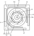
- the indoor unit 31 is a ceiling-embedded type, and includes a substantially rectangular parallelepiped housing 33 embedded in an opening provided in the ceiling, and a decorative panel 47 attached to the lower portion of the housing 33.
- the decorative panel 47 has a rectangular suction grill 39 provided in the center thereof, and four elongated rectangular outlets 37 provided along each side of the suction grill 39.
- the indoor unit 31 includes a centrifugal blower (turbo fan) 51, a heat exchanger 71, a drain pan 45, an air filter 41, a bell mouth 25, and the like in a housing 33.
- the centrifugal blower 51 includes the impeller 23 and the fan motor 11.
- the fan motor 11 is fixed to the approximate center of the top plate of the housing 33.
- the heat exchanger 71 is disposed so as to surround the periphery of the impeller 23 in a state of rising upward from a dish-shaped drain pan 45 extending along the lower end portion thereof.
- the drain pan 45 stores water droplets generated in the heat exchanger 71. The stored water is discharged through a drainage path (not shown). Details of the heat exchanger 71 will be described later.
- the air filter 41 has a size that covers the entrance of the bell mouth 25 and is provided between the bell mouth 25 and the suction grill 39 along the suction grill 39.
- the impeller 23 includes a hub 15, a shroud 19, and a plurality of blades 21.
- the hub 15 is fixed to the lower end portion of the rotating shaft 13 of the fan motor 11.
- the shroud 19 is disposed opposite to the hub 15 on the front F side in the axial direction A of the rotary shaft 13.
- the shroud 19 has an air suction port 19 a that opens in a circle around the rotation shaft 13.
- the plurality of blades 21 are arranged between the hub 15 and the shroud 19 at a predetermined interval along the circumferential direction of the air suction port 19a.
- the bell mouth 25 is disposed opposite to the shroud 19 on the front F side in the axial direction A.
- the bell mouth 25 includes a bell mouth main body and a flange portion that protrudes from the periphery on the front F side of the bell mouth main body to the periphery of the bell mouth main body.
- the bell mouth main body has a through hole 25a penetrating in the front-rear direction.
- the heat exchanger 71 has a plurality of thin plate-like fins 73 and a plurality of heat transfer tube portions P inserted through unillustrated through holes formed in the fins 73.
- This is a cross fin type heat exchanger.
- the plurality of fins 73 are arranged side by side so that the adjacent sides face each other with a gap therebetween.
- the heat exchanger 71 has a plate-like front tube plate 77 disposed so as to be substantially parallel to the fin 73 positioned at one end portion in the juxtaposed direction of the plurality of fins 73 and to cover the fin 73. Yes.
- the heat exchanger 71 has a plate-like rear tube plate 79 arranged so as to be substantially parallel to the fin 73 positioned at the other end portion in the juxtaposed direction and to cover the fin 73.
- Each heat transfer tube portion P is extended between the front tube plate 77 and the rear tube plate 79 along the parallel arrangement direction of the plurality of fins 73. Each heat transfer tube portion P is in contact with the plurality of fins 73.
- the heat exchanger 71 further includes a flow divider 94 and a header 91.
- the shunt 94 includes a shunt main body 95 and a plurality of capillary tubes (branch pipes) 96 branched from the shunt main body 95.
- the shunt 94 is connected to the piping 64 of the refrigerant circuit.
- the header 91 has a header main body 92 and a plurality of branch pipes 93 branched from the header main body 92.
- the header 91 is connected to the piping 61 of the refrigerant circuit.
- a part of the plurality of capillary tubes 96 in the flow divider 94 is connected to an opening end E1 (described later) provided in the rear tube plate 79,
- the remaining portions of the plurality of capillary tubes 96 are connected to an opening end E ⁇ b> 1 (described later) provided on the front tube plate 77.
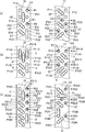
- FIG. 6A is a schematic side view of a part of the rear tube plate 79 as viewed from the direction D1 side in FIG. 4, and the right diagram shows a part of the front tube plate 77 in FIG. It is the schematic side view seen from the direction D2 side.
- FIG. 6A shows an example of a method for connecting the refrigerant tubes.
- FIG. 6A shows three refrigerant pipes (refrigerant paths) R (R1, R2, R3).
- Each refrigerant pipe R is a metal pipe having a pair of open end portions E1 and E2 that serve as refrigerant inlets and outlets and a refrigerant flow path that is continuous inside.
- the plurality of refrigerant tubes R provided in the heat exchanger 71 include, for example, two heat transfer tube portions P and one bent tube portion U that connects these end portions, or three or more heat transfer tube portions P. And a plurality of bent pipe portions U connecting these in series may be included.
- what consists of one heat-transfer pipe part P, ie, the thing formed by one straight pipe, may be contained in the some refrigerant
- Each refrigerant pipe R may be formed by using a so-called hairpin in which one pipe is bent in a U-shape near the center, and ends of straight pipes are connected by a U-shaped U-shaped pipe. May be formed.
- the heat transfer tube portion P refers to a portion of the refrigerant tube R other than the bent tube portion U.
- the heat transfer pipe part P is a part of the straight pipe
- the bent pipe part U is formed of the U-shaped pipe. Part.
- the bent pipe portion U is a folded portion bent at a predetermined radius of curvature
- the heat transfer tube portion P is a portion other than the folded portion.
- the heat transfer tube portion P is extended between the front tube plate 77 and the rear tube plate 79.
- the length of one heat transfer tube portion P is substantially equal to the flow path length of the refrigerant tube R from the front tube plate 77 to the rear tube plate 79. Therefore, the flow path length of the refrigerant pipe R is a value obtained by multiplying the length of the heat transfer pipe part P by the number of the heat transfer pipe parts P, and a value obtained by multiplying the length of the bent pipe part U by the number of the bent pipe parts U.
- the total value is obtained by adding
- Refrigerant pipes R1 and R2 shown in FIG. 6 (a) are odd refrigerant pipes composed of three (odd number) heat transfer pipe portions P and two bent pipe portions U, and four refrigerant pipes R3. It is an even-numbered refrigerant pipe composed of (even number) of heat transfer pipe parts P and three bent pipe parts U.
- the refrigerant pipe R3 having a large flow path length is smaller than the refrigerant pipe R having a small flow path length (refrigerant pipes R1, R2, etc.).
- the refrigerant tube R1 includes the heat transfer tube portions P11, P12, P13, a bent portion U1 that connects the ends of the heat transfer tube portion P11 and the heat transfer tube portion P12 on the front tube plate 77 side, and the rear tube plate.
- the heat transfer tube portion P12 and the bent portion U2 connecting the ends of the heat transfer tube portion P13 are configured.
- the refrigerant tube R2 includes heat transfer tube portions P21, P22, P23, a bent portion U3 connecting the ends of the heat transfer tube portion P21 and the heat transfer tube portion P22 on the front tube plate 77 side, and a heat transfer tube on the rear tube plate 79 side. It is comprised from the bending part U4 which connects the edge parts of part P22 and the heat exchanger tube part P23.
- the refrigerant tube R3 includes heat transfer tube portions P31, P32, P33, P34, a bent portion U5 that connects the ends of the heat transfer tube portion P31 and the heat transfer tube portion P32 on the rear tube plate 79 side, and a front tube plate 77 side.
- the bent portion U6 connects the ends of the heat transfer tube portion P32 and the heat transfer tube portion P33
- the bent portion U7 connects the ends of the heat transfer tube portion P33 and the heat transfer tube portion P34 on the rear tube plate 79 side. ing.
- one capillary tube 96a is connected to the open end E1 (end of the heat transfer tube P31) of the refrigerant tube R3 provided on the front tube plate 77
- the other capillary tube 96 includes an opening end E1 (end portion of the heat transfer tube portion P11) of the refrigerant tube R1 provided on the rear tube plate 79, and an open end portion E1 (end portion of the heat transfer tube portion P21) of the refrigerant tube R2.
- other open ends E1 of other refrigerant pipes R (not shown), respectively (see FIG. 4).
- the plurality of branch pipes 93 of the header 91 are respectively connected to the opening ends E2 of the refrigerant pipes R1, R2, and R3 provided on the front pipe plate 77, and the opening ends E2 of other refrigerant pipes R (not shown). ing. All the open ends E ⁇ b> 2 of the refrigerant tubes R are provided on the front tube plate 77.
- the refrigerant pipe R3 has an even number (four) of the heat transfer pipe sections P, and the other refrigerant pipe R has an odd number of the heat transfer pipe sections P.
- the refrigerant pipe R is an odd multiple of the effective length L and the refrigerant is an even multiple of the effective length L.
- the tube R can be mixed.
- the plurality of refrigerant tubes have only an even number of heat transfer tube portions P, or as shown in FIG. 6 (c), A plurality of refrigerant tubes have only an odd number of heat transfer tube portions P. Specifically, it is as follows.
- the refrigerant pipe R11 includes heat transfer pipe portions P111 to P116 and a plurality of bent portions U that connect the heat transfer tube portions P on the front tube plate 77 side or the rear tube plate 79 side. It is configured.
- the refrigerant pipe R11 has an even number (six) of heat transfer pipe portions P.
- the refrigerant tube R12 includes heat transfer tube portions P121 to P124 and a plurality of bent portions U that connect the heat transfer tube portions P on the front tube plate 77 side or the rear tube plate 79 side.
- the refrigerant pipe R12 has an even number (four) of heat transfer pipe portions P.
- the refrigerant pipe R21 includes heat transfer pipe portions P211 to P213 and a plurality of bent portions U that connect the heat transfer tube portions P to each other on the front tube plate 77 side or the rear tube plate 79 side. It is configured.
- the refrigerant pipe R21 has an odd number (three) of heat transfer pipe portions P.
- the refrigerant tube R22 includes heat transfer tube portions P221 to P223 and a plurality of bent portions U that connect the heat transfer tube portions P on the front tube plate 77 side or the rear tube plate 79 side.
- the refrigerant pipe R22 has an odd number (three) of heat transfer pipe portions P.
- the refrigerant tube R23 includes heat transfer tube portions P231 to P233 and a plurality of bent portions U that connect the heat transfer tube portions P on the front tube plate 77 side or the rear tube plate 79 side.
- the refrigerant pipe R23 has an odd number (three) of heat transfer pipe portions P.
- the refrigerant tube R24 includes heat transfer tube portions P241 to P245 and a plurality of bent portions U that connect the heat transfer tube portions P on the front tube plate 77 side or the rear tube plate 79 side.
- the refrigerant pipe R24 has an odd number (five) of heat transfer pipe portions P.
- all the opening end portions E1 are provided in the rear tube plate 79, and all the opening end portions E2 are provided in the front tube plate 77.
- the effective length L is an odd multiple.
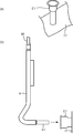
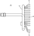
- FIG. 7 is a detailed side view showing an example of a connection destination of each capillary tube 96 of the flow divider 94 in the heat exchanger 71 according to the present embodiment.
- the header 91, the bent pipe portion U, and the like are not shown.
- one capillary tube 96a is connected to the open end E1 located at the lower portion of the front tube plate 77, and the other capillary tubes 96a.
- the tubes 96 are connected to open end portions E1 provided on the rear tube plate 79, respectively.
- this heat exchanger 71 three rows of heat transfer tube portions P are arranged up to the position of the two-dot chain line Q. One column is omitted, and only the outer two columns are arranged.
- the capillary tube 96a (96) connected to the opening end E1 of the refrigerant pipe R3 having a large flow path length is connected to the opening end E1 of the refrigerant pipes R1 and R2 having a small flow path length.
- the pressure loss during refrigerant circulation is larger than that of the branch pipe 96.
- the heat exchanger 71 of the present embodiment is arranged in a state of standing upward from the drain pan 45.
- the drain pan 45 has a bottom portion 45a and a pair of side wall portions 45b extending upward from both sides of the bottom portion 45a. Accordingly, the lower portion of the heat exchanger 71 is disposed so as to face the side wall portion 45 b of the drain pan 45, and the drain pan 45 hinders the smooth flow of air in the lower portion of the heat exchanger 71.
- the air speed when air passes through the heat exchanger 71 is smaller than other parts (for example, near the center in the height direction), and the efficiency of heat exchange tends to be low. .
- the number of heat transfer pipe portions P used for the refrigerant pipe R provided in the lower part of the heat exchanger 71 or in the vicinity thereof is made larger than that in other parts.
- the number of heat transfer pipe portions P used for the refrigerant pipe R3 located at the lower part of the heat exchanger 71 is four, and the upper refrigerant pipes R1, R2 are used.
- the number of heat transfer tube portions P used in the above is three.
- the refrigerant pipe R is more suitable according to the wind speed of air that differs for each part of the heat exchanger 71. The length can be adjusted.
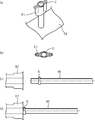
- the opening end E1 on the rear tube plate 79 side to which the capillary tube 96a is connected and the opening end E1 on the front tube plate 77 side to which the other capillary tube 96 is connected are formed to have different shapes. Yes. As shown in FIGS. 8A and 8B, the opening end E1 on the rear tube plate 79 side has a structure in which both sides are crushed into a flat shape. On the other hand, as shown in FIG. 9A, the opening end E1 on the front tube plate 77 side has a structure in which the diameter is increased so that the diameter of the front end is increased. Thereby, it is possible to prevent an operator from mistakenly connecting the connection destinations of the capillary tubes 96 when connecting the capillary tubes 96.
- a circular opening C into which the tip of the capillary tube 96 is fitted is formed near the center of the flat structure of the opening end E1 on the rear tube plate 79 side.
- a stopper S is formed in the vicinity of the distal end portion of the capillary tube 96 so as to protrude from other portions.
- a diameter expansion pipe K is connected to the tip of the capillary tube 96a so as to match the diameter of the opening end E1 on the front tube plate 77 side.
- a tip K1 of the pipe K is connected to the open end E1 and brazed.
- the flow of the refrigerant in each of the refrigerant pipes R1, R2, and R3 in FIG. 6A will be described by taking the case of the cooling operation as an example.
- the refrigerant is sent to the heat exchanger 71 through the pipe 64 of FIG.
- the refrigerant sent through the pipe 64 flows into the flow divider main body 95, branches into a plurality of capillary tubes 96, and opens at the open end E ⁇ b> 1 to which each branch pipe 96 is connected.
- each refrigerant pipe R reaches the opening end E2 of each refrigerant pipe R through the heat transfer pipe portion P and the bent portion U, and the header 91 connected to each opening end E2. It merges with the header body 92 through the branch pipe 93. This refrigerant flows to the four-way switching valve 86 side through the pipe 61 connected to the header main body 92.
- the shunt or the header is configured such that a part of the plurality of branch pipes is connected to the opening end portion on the one tube sheet side, and the remaining parts of the plurality of branch pipes are It is connected to the opening end on the other tube sheet side.
- the plurality of refrigerant tubes can include an even-numbered refrigerant tube having an even number of the heat transfer tube portions and an odd-number refrigerant tube having an odd number of the heat transfer tube portions.
- an even-numbered refrigerant tube having an even number of heat transfer tube portions and an odd-numbered refrigerant tube having an odd number of heat transfer tube portions are provided. They could not be mixed, and all of the plurality of refrigerant tubes were either even-numbered refrigerant tubes or odd-numbered refrigerant tubes.
- the effective length of one heat transfer tube portion is L
- the heat transfer tube portion is equivalent to two. The length, that is, the length 2L was the smallest unit for adjusting the flow path length.
- the flow path length of each refrigerant pipe is the length of one heat transfer pipe portion, that is, the length L Is the smallest unit for adjusting the channel length.
- the flow path length can be adjusted more finely than in the prior art, so that the flow path length of each refrigerant pipe can be adjusted to a more suitable length for each part of the heat exchanger. Therefore, the heat exchange performance of the heat exchanger can be finely adjusted for each part of the heat exchanger.
- the flow path length can be adjusted for each length L, the pressure loss due to increasing the flow path length is too large compared to the conventional case where the flow path length is adjusted for every 2 L length. Can be suppressed.
- the larger one of the refrigerant pipes is longer than the part where the smaller one is disposed.
- part with a small wind speed at the time of air passing between fins.
- the branch pipe connected to the opening end of the refrigerant pipe having the larger flow path length is more than the branch pipe connected to the opening end of the refrigerant pipe having the smaller flow path length.
- the flow rate (circulation amount) of the refrigerant flowing to the refrigerant pipe to which the branch pipe is connected is adjusted by adjusting the pressure loss in the branch pipe. That is, the branch pipe connected to the opening end of the refrigerant pipe having the larger flow path length is more than the branch pipe connected to the opening end of the refrigerant pipe having the smaller flow path length. Since the pressure loss during the circulation of the refrigerant is large, the flow resistance during the circulation of the refrigerant increases. As a result, the refrigerant circulation amount (circulation amount) can be made relatively smaller than other refrigerant pipes.
- the refrigerant pipe further promotes the phase change of the refrigerant.
- the plurality of branch pipes of the header are connected to an opening end portion on the one tube sheet side, and a part of the plurality of branch pipes of the flow divider is an opening end on the one tube sheet side.
- the remaining part of the plurality of branch pipes of the flow divider is connected to an opening end portion on the other tube sheet side, and the diversion flow connected to the opening end portion on the one tube sheet side It is preferable that the number of branch pipes of the distributor is smaller than the number of branch pipes of the flow divider connected to the opening end on the other tube sheet side.
- a part of the plurality of capillary tubes 96 of the flow divider 94 is connected to the opening end of the front tube plate 77 and the rest is connected to the opening end of the rear tube plate 79.
- the plurality of branch pipes 93 of the header 91 are all connected to the opening end portion of the front tube plate 77, but are not limited thereto.
- a part of the plurality of branch pipes 93 of the header 91 may be connected to the opening end portion of the front tube plate 77 and the rest may be connected to the opening end portion of the rear tube plate 79.
- the capillary tube 96 of the flow divider 94 is connected to the branch pipe 93 of the header 91.
- the diameter is small and the structure is easy to deform.
- the plurality of branch pipes 93 of the header 91 are concentrically connected to the opening end of one of the front tube plate 77 and the rear tube plate 79, and the plurality of capillary tubes 96 of the flow divider 94 are connected to the front tube plate 77. It is preferable to connect the opening end of the tube plate 77 and the opening end of the rear tube plate 79 separately. Thus, it is excellent in workability and workability to connect the plurality of capillary tubes 96 of the flow divider 94 separately.
- tube R in the lower part of the heat exchanger 71 located in the vicinity of the drain pan 45 is increased rather than another site
- the air flow rate tends to be smaller than that in the vicinity of the center of the heat exchanger 71 in the height direction. Therefore, in the vicinity of the inner surface of the housing, the number of the heat transfer tube portions P constituting the refrigerant tube R may be larger than other portions (for example, near the center). Thereby, heat exchange efficiency can be improved also near the inner surface of the housing.
Landscapes
- Engineering & Computer Science (AREA)
- Mechanical Engineering (AREA)
- General Engineering & Computer Science (AREA)
- Physics & Mathematics (AREA)
- Thermal Sciences (AREA)
- Chemical & Material Sciences (AREA)
- Combustion & Propulsion (AREA)
- Heat-Exchange Devices With Radiators And Conduit Assemblies (AREA)
- Air Filters, Heat-Exchange Apparatuses, And Housings Of Air-Conditioning Units (AREA)
Abstract
Description
図1に示すように、空気調和機81は、室内機31と室外機82とを備えている。この空気調和機81は、室内機31に配設された熱交換器71と、室外機82に配設された圧縮機83、熱交換器84および膨張弁85と、これらを接続する配管61~64とを含む冷媒回路を備えている。この空気調和機81は、冷媒回路の配管の一部に配設された四路切換弁86により冷媒の流れ方向を切り換えることによって、冷房運転と暖房運転を切り換えることができる。室内機31は送風機51を備え、室外機82は送風機87を備えている。
図2に示すように、室内機31は、天井埋込型であり、天井に設けられた開口に埋め込まれる略直方体の筐体33と、筐体33の下部に取り付けられた化粧パネル47とを備えている。化粧パネル47は、その中央部に設けられた矩形状の吸込グリル39と、この吸込グリル39の各辺に沿って設けられた細長い矩形状の4つの吹出口37とを有している。
図4及び図5に示すように、熱交換器71は、薄板状の複数のフィン73と、各フィン73に形成された図略の貫通孔に挿通された複数の伝熱管部Pとを有するクロスフィン型の熱交換器である。複数のフィン73は、隣同士が互いに隙間をあけた状態で対面するように並設されている。熱交換器71は、複数のフィン73の並設方向の一方の端部に位置するフィン73に略平行で、このフィン73を覆うように配置された板状の前管板77を有している。また、熱交換器71は、前記並設方向の他方の端部に位置するフィン73に略平行で、このフィン73を覆うように配置された板状の後管板79を有している。
上記実施形態をまとめると、以下の通りである。
以上、本発明の実施形態について説明したが、本発明は、上述した実施形態に限定されることなく、種々の形態で実施することができる。例えば、前記実施形態では、室内機に用いられる熱交換器を例に挙げて説明したが、本発明の熱交換器は、室外機用にも適用可能である。
71 熱交換器
73 フィン
77 前管板
79 後管板
91 ヘッダ
92 ヘッダ本体
93 分岐管
94 分流器
95 分流器本体
96 キャピラリーチューブ(分岐管)
P 伝熱管部
P11~P13 冷媒管R1の伝熱管部
P21~P23 冷媒管R2の伝熱管部
P31~P34 冷媒管R3の伝熱管部
R(R1,R2,R3) 冷媒管
U 屈曲部
Claims (4)
- 空気調和機に用いられる熱交換器であって、
隣同士が互いに隙間をあけた状態で対面するように並設された複数のフィン(73)と、
前記複数のフィン(73)の並設方向の一方の端部と他方の端部に位置する一対の管板(77,79)と、
冷媒の出入口となる一対の開口端部(E1,E2)を有する複数の冷媒管(R)と、
複数の分岐管(96)を有し、対応する冷媒管(R)の一方の前記開口端部(E1)に各分岐管(96)が接続された分流器(94)と、
複数の分岐管(93)を有し、対応する冷媒管(R)の他方の前記開口端部(E2)に各分岐管(93)が接続されたヘッダ(91)と、を備え、
前記複数の冷媒管(R)における各冷媒管(R)は、前記一対の管板間において前記複数のフィン(73)と接した状態で前記複数のフィン(73)の並設方向に沿って延設された複数の伝熱管部(P)と、2つの伝熱管部(P)の端部同士をつなぐ屈曲管部(U)とを含み、
各開口端部は、一方の前記管板(77)又は他方の前記管板(79)に配置されており、
前記複数の冷媒管(R)は、偶数本の前記伝熱管部(P)を有する偶数冷媒管(R)と、奇数本の前記伝熱管部(P)を有する奇数冷媒管(R)とを含み、
前記分流器(94)又は前記ヘッダ(91)は、前記複数の分岐管の一部が前記一方の管板(77)側の前記開口端部に接続され、前記複数の分岐管の残部が前記他方の管板(79)側の前記開口端部に接続されている、熱交換器。 - 前記偶数冷媒管(R)と前記奇数冷媒管(R)のうち、冷媒管(R)の流路長の大きい方は、前記流路長の小さい方が配設されている部位よりも前記フィン(73)間を空気が通過する際の風速が小さい部位に配設されている、請求項1に記載の熱交換器。
- 前記流路長の大きい方の冷媒管(R)の前記開口端部(E1)に接続される前記分岐管は、前記流路長の小さい方の冷媒管(R)の前記開口端部(E1)に接続される前記分岐管よりも冷媒流通時の圧力損失が大きい、請求項2に記載の熱交換器。
- 前記ヘッダ(91)の前記複数の分岐管(93)は、前記一方の管板(77)側の開口端部(E2)に接続され、
前記分流器(94)の前記複数の分岐管(96)の一部は、前記一方の管板(77)側の開口端部(E1)に接続され、前記分流器(94)の前記複数の分岐管(96)の残部は、前記他方の管板(79)側の開口端部(E1)に接続されており、前記一方の管板(77)側の開口端部(E1)に接続された前記分流器(94)の分岐管(96)の数は、前記他方の管板(79)側の開口端部(E1)に接続された前記分流器(94)の分岐管(96)の数よりも少ない、請求項1~3のいずれか1項に記載の熱交換器。
Priority Applications (7)
| Application Number | Priority Date | Filing Date | Title |
|---|---|---|---|
| CN201180009534.5A CN102753927B (zh) | 2010-02-15 | 2011-02-02 | 空调机用热交换器 |
| BR112012020449A BR112012020449B1 (pt) | 2010-02-15 | 2011-02-02 | trocador de calor para um condicionador de ar |
| AU2011215523A AU2011215523B2 (en) | 2010-02-15 | 2011-02-02 | Heat exchanger for air conditioner |
| US13/578,995 US9618269B2 (en) | 2010-02-15 | 2011-02-02 | Heat exchanger with tube arrangement for air conditioner |
| EP11742006.7A EP2535677B1 (en) | 2010-02-15 | 2011-02-02 | Heat exchanger for air conditioner |
| KR1020127023637A KR101365846B1 (ko) | 2010-02-15 | 2011-02-02 | 공기 조화기용 열교환기 |
| ES11742006.7T ES2539719T3 (es) | 2010-02-15 | 2011-02-02 | Intercambiador de calor para acondicionador de aire |
Applications Claiming Priority (2)
| Application Number | Priority Date | Filing Date | Title |
|---|---|---|---|
| JP2010-030649 | 2010-02-15 | ||
| JP2010030649A JP4715963B1 (ja) | 2010-02-15 | 2010-02-15 | 空気調和機用熱交換器 |
Publications (1)
| Publication Number | Publication Date |
|---|---|
| WO2011099256A1 true WO2011099256A1 (ja) | 2011-08-18 |
Family
ID=44350468
Family Applications (1)
| Application Number | Title | Priority Date | Filing Date |
|---|---|---|---|
| PCT/JP2011/000583 Ceased WO2011099256A1 (ja) | 2010-02-15 | 2011-02-02 | 空気調和機用熱交換器 |
Country Status (9)
| Country | Link |
|---|---|
| US (1) | US9618269B2 (ja) |
| EP (1) | EP2535677B1 (ja) |
| JP (1) | JP4715963B1 (ja) |
| KR (1) | KR101365846B1 (ja) |
| CN (1) | CN102753927B (ja) |
| AU (1) | AU2011215523B2 (ja) |
| BR (1) | BR112012020449B1 (ja) |
| ES (1) | ES2539719T3 (ja) |
| WO (1) | WO2011099256A1 (ja) |
Families Citing this family (10)
| Publication number | Priority date | Publication date | Assignee | Title |
|---|---|---|---|---|
| WO2014115240A1 (ja) * | 2013-01-22 | 2014-07-31 | 三菱電機株式会社 | 冷媒分配器及びこの冷媒分配器を用いたヒートポンプ装置 |
| JP5811134B2 (ja) | 2013-04-30 | 2015-11-11 | ダイキン工業株式会社 | 空気調和機の室内ユニット |
| JP6180338B2 (ja) * | 2014-01-29 | 2017-08-16 | ジョンソンコントロールズ ヒタチ エア コンディショニング テクノロジー(ホンコン)リミテッド | 空気調和機 |
| WO2016056086A1 (ja) * | 2014-10-08 | 2016-04-14 | 三菱電機株式会社 | 冷媒配管及びヒートポンプ装置 |
| JP6213543B2 (ja) * | 2015-10-28 | 2017-10-18 | ダイキン工業株式会社 | 熱交換器 |
| US20180292096A1 (en) * | 2015-10-28 | 2018-10-11 | Mitsubishi Electric Corporation | Outdoor unit and indoor unit of air-conditioning apparatus |
| CN106352728A (zh) * | 2016-09-27 | 2017-01-25 | 广东美的制冷设备有限公司 | 连接管组件、换热器组件及空调器 |
| CN106323067A (zh) * | 2016-10-28 | 2017-01-11 | 广东美的制冷设备有限公司 | 连接管组件、换热器组件及空调器 |
| EP3647603A1 (en) | 2018-10-31 | 2020-05-06 | Carrier Corporation | Arrangement of centrifugal impeller of a fan for reducing noise |
| CN114459080B (zh) * | 2022-03-11 | 2024-09-24 | 珠海格力电器股份有限公司 | 一种换热器和空调器 |
Citations (6)
| Publication number | Priority date | Publication date | Assignee | Title |
|---|---|---|---|---|
| JPH09229467A (ja) * | 1996-02-26 | 1997-09-05 | Matsushita Refrig Co Ltd | 熱交換器 |
| JP2001304791A (ja) * | 2000-04-14 | 2001-10-31 | Daikin Ind Ltd | 熱交換器 |
| JP2002181487A (ja) * | 2000-12-12 | 2002-06-26 | Daikin Ind Ltd | 空気調和機用熱交換器 |
| JP2004279029A (ja) * | 2004-07-02 | 2004-10-07 | Hitachi Ltd | 室内機 |
| JP2007278676A (ja) | 2006-04-12 | 2007-10-25 | Matsushita Electric Ind Co Ltd | 熱交換器 |
| JP2008121984A (ja) * | 2006-11-13 | 2008-05-29 | Matsushita Electric Ind Co Ltd | 熱交換器ユニット |
Family Cites Families (17)
| Publication number | Priority date | Publication date | Assignee | Title |
|---|---|---|---|---|
| JPS5264733A (en) * | 1975-11-21 | 1977-05-28 | Hitachi Ltd | Evaporator |
| US4089368A (en) * | 1976-12-22 | 1978-05-16 | Carrier Corporation | Flow divider for evaporator coil |
| US4554968A (en) * | 1982-01-29 | 1985-11-26 | Carrier Corporation | Wrapped fin heat exchanger circuiting |
| US5065586A (en) * | 1990-07-30 | 1991-11-19 | Carrier Corporation | Air conditioner with dehumidifying mode |
| JPH0518612A (ja) | 1991-07-09 | 1993-01-26 | Toshiba Corp | 冷凍装置 |
| JPH07208821A (ja) * | 1994-01-17 | 1995-08-11 | Toshiba Corp | 空気調和装置 |
| JPH08219493A (ja) | 1995-02-09 | 1996-08-30 | Daikin Ind Ltd | 空気調和機 |
| KR0175913B1 (ko) | 1996-03-30 | 1999-10-01 | 김광호 | 공기조화기의 실내기용 튜브식 열교환기 |
| KR100244332B1 (ko) * | 1997-10-09 | 2000-03-02 | 윤종용 | 공기조화기의 열교환기 |
| KR100261476B1 (ko) * | 1998-03-06 | 2000-07-01 | 윤종용 | 분리형 공기 조화기의 증발기 |
| KR100332773B1 (ko) * | 1999-09-13 | 2002-04-17 | 구자홍 | 히트 펌프의 증발기 유량 분배장치 |
| JP2001263702A (ja) | 2000-03-24 | 2001-09-26 | Sanyo Electric Co Ltd | 空気調和装置及び熱交換器の製造方法 |
| US6354367B1 (en) * | 2001-02-12 | 2002-03-12 | Rheem Manufacturing Company | Air conditioning unit having coil portion with non-uniform fin arrangement |
| ES2316640T3 (es) * | 2001-12-21 | 2009-04-16 | BEHR GMBH & CO. KG | Intercambiador de calor, en particular para un vehiculo automovil. |
| WO2004025207A1 (ja) * | 2002-09-10 | 2004-03-25 | Gac Corporation | 熱交換器およびその製造方法 |
| JP4506609B2 (ja) * | 2005-08-08 | 2010-07-21 | 三菱電機株式会社 | 空気調和機及び空気調和機の製造方法 |
| JP2010078289A (ja) | 2008-09-29 | 2010-04-08 | Mitsubishi Electric Corp | 熱交換器及びこの熱交換器を備えた空気調和機 |
-
2010
- 2010-02-15 JP JP2010030649A patent/JP4715963B1/ja active Active
-
2011
- 2011-02-02 ES ES11742006.7T patent/ES2539719T3/es active Active
- 2011-02-02 WO PCT/JP2011/000583 patent/WO2011099256A1/ja not_active Ceased
- 2011-02-02 CN CN201180009534.5A patent/CN102753927B/zh active Active
- 2011-02-02 BR BR112012020449A patent/BR112012020449B1/pt active IP Right Grant
- 2011-02-02 AU AU2011215523A patent/AU2011215523B2/en active Active
- 2011-02-02 KR KR1020127023637A patent/KR101365846B1/ko active Active
- 2011-02-02 US US13/578,995 patent/US9618269B2/en active Active
- 2011-02-02 EP EP11742006.7A patent/EP2535677B1/en active Active
Patent Citations (6)
| Publication number | Priority date | Publication date | Assignee | Title |
|---|---|---|---|---|
| JPH09229467A (ja) * | 1996-02-26 | 1997-09-05 | Matsushita Refrig Co Ltd | 熱交換器 |
| JP2001304791A (ja) * | 2000-04-14 | 2001-10-31 | Daikin Ind Ltd | 熱交換器 |
| JP2002181487A (ja) * | 2000-12-12 | 2002-06-26 | Daikin Ind Ltd | 空気調和機用熱交換器 |
| JP2004279029A (ja) * | 2004-07-02 | 2004-10-07 | Hitachi Ltd | 室内機 |
| JP2007278676A (ja) | 2006-04-12 | 2007-10-25 | Matsushita Electric Ind Co Ltd | 熱交換器 |
| JP2008121984A (ja) * | 2006-11-13 | 2008-05-29 | Matsushita Electric Ind Co Ltd | 熱交換器ユニット |
Non-Patent Citations (1)
| Title |
|---|
| See also references of EP2535677A4 |
Also Published As
| Publication number | Publication date |
|---|---|
| US9618269B2 (en) | 2017-04-11 |
| ES2539719T3 (es) | 2015-07-03 |
| EP2535677A1 (en) | 2012-12-19 |
| US20120318487A1 (en) | 2012-12-20 |
| KR101365846B1 (ko) | 2014-02-21 |
| BR112012020449B1 (pt) | 2020-04-07 |
| AU2011215523A1 (en) | 2012-09-13 |
| CN102753927B (zh) | 2014-06-18 |
| EP2535677A4 (en) | 2013-12-25 |
| AU2011215523B2 (en) | 2013-06-20 |
| EP2535677B1 (en) | 2015-04-01 |
| JP2011163741A (ja) | 2011-08-25 |
| KR20120125534A (ko) | 2012-11-15 |
| JP4715963B1 (ja) | 2011-07-06 |
| BR112012020449A2 (pt) | 2016-05-17 |
| CN102753927A (zh) | 2012-10-24 |
Similar Documents
| Publication | Publication Date | Title |
|---|---|---|
| JP4715963B1 (ja) | 空気調和機用熱交換器 | |
| CN103392109B (zh) | 空调机用热交换器 | |
| JP2010164222A (ja) | フィン付き熱交換器 | |
| JPWO2014091782A1 (ja) | 扁平管熱交換器、及びそれを備えた空気調和機の室外機 | |
| JP2010249343A (ja) | フィンチューブ型熱交換器及びこれを用いた空気調和機 | |
| JP5062265B2 (ja) | 空気調和機 | |
| JP6223596B2 (ja) | 空気調和装置の室内機 | |
| JP5014372B2 (ja) | フィンチューブ型熱交換器並びに空調冷凍装置 | |
| JP2016200338A (ja) | 空気調和機 | |
| WO2014155560A1 (ja) | 熱交換器およびこれを用いた冷凍サイクル空調装置 | |
| JP2010216718A (ja) | フィン付き熱交換器 | |
| JP6260632B2 (ja) | 熱交換器 | |
| JP2011112315A (ja) | フィンチューブ型熱交換器及びこれを用いた空気調和機 | |
| JP2016050718A (ja) | 空気調和機 | |
| JP2019015432A (ja) | 熱交換器及び熱交換ユニット | |
| JP2017133814A (ja) | 熱交換器 | |
| JP2006336909A (ja) | 凝縮器及びこれを用いた空気調和機用室内ユニット | |
| CN116724209B (zh) | 热交换器 | |
| JP6455452B2 (ja) | 熱交換器 | |
| JP2007255785A (ja) | フィン付き熱交換器及び空気調和機 | |
| JP4862218B2 (ja) | 空気調和機 | |
| JP2014047959A (ja) | 熱交換器及びそれを搭載した冷凍サイクル装置 | |
| KR100898116B1 (ko) | 열교환기의 전열핀 | |
| JP2008249299A (ja) | フィンチューブ型熱交換器および空気調和装置 | |
| JP6413376B2 (ja) | フィンチューブ型熱交換器及びその製造方法 |
Legal Events
| Date | Code | Title | Description |
|---|---|---|---|
| WWE | Wipo information: entry into national phase |
Ref document number: 201180009534.5 Country of ref document: CN |
|
| 121 | Ep: the epo has been informed by wipo that ep was designated in this application |
Ref document number: 11742006 Country of ref document: EP Kind code of ref document: A1 |
|
| WWE | Wipo information: entry into national phase |
Ref document number: 13578995 Country of ref document: US |
|
| NENP | Non-entry into the national phase |
Ref country code: DE |
|
| WWE | Wipo information: entry into national phase |
Ref document number: 2222/KOLNP/2012 Country of ref document: IN |
|
| WWE | Wipo information: entry into national phase |
Ref document number: 2011215523 Country of ref document: AU |
|
| ENP | Entry into the national phase |
Ref document number: 20127023637 Country of ref document: KR Kind code of ref document: A |
|
| WWE | Wipo information: entry into national phase |
Ref document number: 2011742006 Country of ref document: EP |
|
| ENP | Entry into the national phase |
Ref document number: 2011215523 Country of ref document: AU Date of ref document: 20110202 Kind code of ref document: A |
|
| REG | Reference to national code |
Ref country code: BR Ref legal event code: B01A Ref document number: 112012020449 Country of ref document: BR |
|
| ENP | Entry into the national phase |
Ref document number: 112012020449 Country of ref document: BR Kind code of ref document: A2 Effective date: 20120815 |