WO2011099561A1 - 清掃具 - Google Patents
清掃具 Download PDFInfo
- Publication number
- WO2011099561A1 WO2011099561A1 PCT/JP2011/052867 JP2011052867W WO2011099561A1 WO 2011099561 A1 WO2011099561 A1 WO 2011099561A1 JP 2011052867 W JP2011052867 W JP 2011052867W WO 2011099561 A1 WO2011099561 A1 WO 2011099561A1
- Authority
- WO
- WIPO (PCT)
- Prior art keywords
- cleaning
- handle
- cleaning tool
- end portion
- cleaning head
- Prior art date
- Legal status (The legal status is an assumption and is not a legal conclusion. Google has not performed a legal analysis and makes no representation as to the accuracy of the status listed.)
- Ceased
Links
Images


















Classifications
-
- A—HUMAN NECESSITIES
- A47—FURNITURE; DOMESTIC ARTICLES OR APPLIANCES; COFFEE MILLS; SPICE MILLS; SUCTION CLEANERS IN GENERAL
- A47L—DOMESTIC WASHING OR CLEANING; SUCTION CLEANERS IN GENERAL
- A47L13/00—Implements for cleaning floors, carpets, furniture, walls, or wall coverings
- A47L13/10—Scrubbing; Scouring; Cleaning; Polishing
- A47L13/20—Mops
- A47L13/24—Frames for mops; Mop heads
-
- A—HUMAN NECESSITIES
- A47—FURNITURE; DOMESTIC ARTICLES OR APPLIANCES; COFFEE MILLS; SPICE MILLS; SUCTION CLEANERS IN GENERAL
- A47L—DOMESTIC WASHING OR CLEANING; SUCTION CLEANERS IN GENERAL
- A47L13/00—Implements for cleaning floors, carpets, furniture, walls, or wall coverings
- A47L13/10—Scrubbing; Scouring; Cleaning; Polishing
- A47L13/20—Mops
-
- A—HUMAN NECESSITIES
- A47—FURNITURE; DOMESTIC ARTICLES OR APPLIANCES; COFFEE MILLS; SPICE MILLS; SUCTION CLEANERS IN GENERAL
- A47L—DOMESTIC WASHING OR CLEANING; SUCTION CLEANERS IN GENERAL
- A47L13/00—Implements for cleaning floors, carpets, furniture, walls, or wall coverings
- A47L13/10—Scrubbing; Scouring; Cleaning; Polishing
- A47L13/20—Mops
- A47L13/24—Frames for mops; Mop heads
- A47L13/254—Plate frames
-
- A—HUMAN NECESSITIES
- A47—FURNITURE; DOMESTIC ARTICLES OR APPLIANCES; COFFEE MILLS; SPICE MILLS; SUCTION CLEANERS IN GENERAL
- A47L—DOMESTIC WASHING OR CLEANING; SUCTION CLEANERS IN GENERAL
- A47L13/00—Implements for cleaning floors, carpets, furniture, walls, or wall coverings
- A47L13/10—Scrubbing; Scouring; Cleaning; Polishing
- A47L13/20—Mops
- A47L13/24—Frames for mops; Mop heads
- A47L13/254—Plate frames
- A47L13/256—Plate frames for mops made of cloth
-
- B—PERFORMING OPERATIONS; TRANSPORTING
- B25—HAND TOOLS; PORTABLE POWER-DRIVEN TOOLS; MANIPULATORS
- B25G—HANDLES FOR HAND IMPLEMENTS
- B25G1/00—Handle constructions
- B25G1/04—Handle constructions telescopic; extensible; sectional
Definitions
- the present invention relates to a cleaning tool that removes dust and dirt on a surface to be cleaned by a cleaning tool body that covers the cleaning surface and is fitted with a cleaning sheet.
- cleaning tools for cleaning the floor surface various cleaning tools including a cleaning head to which a mop, a cleaning sheet, and the like are attached, and a handle rotatably connected to the upper surface of the cleaning head via a joint portion are known. ing. In general, these cleaning tools not only rotate the handle vertically with respect to the cleaning head, but also allow the handle to rotate 360 degrees in the circumferential direction around the joint. Thus, the floor surface or the like can be efficiently cleaned while the cleaning surface of the cleaning head is directed in an arbitrary direction (see, for example, Patent Document 3).
- a handle for such a cleaning tool insert the male end of one cylindrical pipe into the female end of the other cylindrical pipe and match the male protrusion insertion hole with the female protrusion insertion hole.
- a plurality of cylindrical shapes are formed by a pipe connection structure configured to lock the engagement protrusion from the outside and cover the joint portion between the male end and the female end from the outside and attach a sleeve-like member.
- a pipe that is connected and integrated in the axial direction has been developed (for example, see Patent Document 4).
- a bifurcated head side yoke portion provided at the center of the upper surface of the cleaning head and a lower end portion of the handle
- the provided bifurcated handle side yoke portion is connected via a connecting member having a first rotation axis portion and a second rotation axis portion whose central axes are orthogonal to each other.
- a connecting member having a first rotation axis portion and a second rotation axis portion whose central axes are orthogonal to each other.
- a cleaning tool to wipe off the floor surface to remove dust and dirt a cleaning tool with a length of about 100 to 150 cm, for example, suitable for cleaning work while standing is attached to the main body of the cleaning tool such as a mop. Tools are used a lot.
- a cleaning tool for cleaning the floor surface it comprises a cleaning head on which a disposable cleaning sheet is detachably mounted, and a handle rotatably connected to the upper surface portion of the cleaning head via a joint portion.
- Various cleaning tools are known.
- these cleaning tools there are four cleaning sheet mounting tools made of a flexible elastic material having a slit for engagement on the upper surface of the cleaning head, for example, close to each corner of the rectangular cleaning head. After the cleaning sheet is wrapped around the cleaning head so as to cover the bottom surface of the cleaning head from below, the edge of the cleaning sheet is pushed into the slit of the sheet mounting tool on the upper surface of the cleaning head. By engaging, the cleaning sheet can be easily attached to the cleaning head so as to be detachable and replaceable (see, for example, Patent Document 7).
- a cleaning tool has been developed that improves the engagement of the cleaning sheet that is pushed into the sheet mounting tool and is attached so that the cleaning sheet does not easily come off the cleaning head during cleaning (for example, Patent Document 8). reference).
- a slit for engagement provided on a cleaning sheet mounting tool made of a flexible elastic material is extended in a direction perpendicular to the direction of the tensile force acting on the cleaning sheet to form a sawtooth shape.
- a plurality of opening slits extending radially from the central portion of the holding slit, and the edge of the cleaning sheet is attached to the sawtooth holding slit.
- the present invention includes a cleaning tool main body including a cleaning head, a base body attached to cover the lower surface of the cleaning head, and a handle portion attached to a surface opposite to the lower surface of the cleaning head, It is a cleaning tool that covers a cleaning surface by a lower surface of a base body and is attached with a cleaning sheet and wipes the surface to be cleaned with the cleaning sheet.
- the bottom surface of the base body has a corrugated cross-sectional shape in which a cross section in a direction perpendicular to the predetermined direction in which the cleaning is performed by the cleaning tool main body is alternately arranged in a crest and a trough.
- a corrugated surface is provided.
- the valley portion of the corrugated uneven surface portion is an oblique valley portion having an end portion opened to a side portion facing the predetermined direction of the base body and extending obliquely with respect to the predetermined direction. have.
- the handle portion is a handle, and the handle is preferably formed by connecting a plurality of cylindrical pipes by a pipe connecting structure that connects and integrates a pair of cylindrical pipes in the axial direction.
- the pipe connection structure is such that the male side end of one cylindrical pipe is inserted into the female side end of the other cylindrical pipe, and the male side projection insertion hole and the female side projection insertion hole are matched to each other from the outside. It is preferable that the engaging protrusion is locked and the sleeve-like member is attached so as to cover the joint portion between the male side end portion and the female side end portion from the outside.
- the female side end portion is provided with a positioning guide rib that protrudes inward from the inner peripheral surface of the female side end portion at a portion away from the female side protrusion insertion hole in the circumferential direction, and the male side
- the end portion is provided with a guide groove corresponding to the positioning guide rib extending in the axial direction from the distal end edge portion of the male side end portion at a portion away from the male side protrusion insertion hole in the circumferential direction.
- the male side projection insertion hole is aligned with the female side projection insertion hole while the positioning guide rib of the female side end portion is locked and guided in the guide groove of the male side end portion. It is preferable that an end is inserted into the female side end.
- the handle portion is a handle, and the handle is preferably formed by connecting a plurality of cylindrical pipes by a pipe connecting structure that connects and integrates a pair of cylindrical pipes in the axial direction.
- the pipe connection structure is such that the male side end of one cylindrical pipe is inserted into the female side end of the other cylindrical pipe, and the male side projection insertion hole and the female side projection insertion hole are matched to each other from the outside. It is preferable that the engaging protrusion is locked and the sleeve-like member is attached so as to cover the joint portion between the male side end portion and the female side end portion from the outside.
- the sleeve-like member is provided with a contact rib that protrudes inward from the inner peripheral surface of the portion covering the joint portion and that the end surface of the female side end portion contacts from the rear side continuously or intermittently in the circumferential direction.
- the contact rib is provided with an insertion guide inclined portion extending obliquely outward in the radial direction toward the distal end side of the sleeve-like member, continuously or intermittently provided in the circumferential direction, With the end face abutting against the abutment surface of the abutment rib and the sleeve-like member attached to the female end of the other cylindrical pipe, the male end of the one cylindrical pipe is It is preferable that the insertion guide is inclined and inserted into the female side end.
- the handle portion is a handle, and an end cap is preferably attached to the upper end of the handle.
- the end cap is made of an elastic material, and is attached to the upper end portion of the handle via a mounting hole, and a covering end surface arranged to cover the end surface portion of the handle is perpendicular to the central axis direction of the handle.
- the tapered tip end edge portion of the end cap is a cushion that can be elastically deformed inward and outward in the radial direction centered on the central axis direction of the handle It is preferable to form the part.
- the handle portion is a handle, and includes a joint structure of a cleaning head that allows the handle to be rotated 360 degrees in a circumferential direction around the joint portion in a state where the handle is disposed substantially parallel to the cleaning head.
- the cleaning head joint structure has a bifurcated head-side yoke portion protruding from the upper surface of the cleaning head and a bifurcated handle-side yoke portion provided at the lower end of the handle, the central axis of which is It is preferable that the joint portion that is rotatable in the vertical direction and the circumferential direction is formed by connecting via a connecting member that includes a first rotation axis portion and a second rotation axis portion that are orthogonal to each other. .
- Each of the opposing surfaces arranged with a gap between the pair of yoke protrusions constituting the head side yoke portion has a symmetrical mountain-shaped outer peripheral edge portion having inclined portions on both sides of the top portion, and
- the pair of yoke pieces constituting the side yoke portion has a width that is substantially the same as the interval width between the opposing surfaces of the pair of yoke protrusions, and the handle is disposed in a state substantially parallel to the cleaning head. It is preferable that the side edge portion of any one of the yoke pieces can be brought into contact with the outer peripheral edge portion of the facing surface of any one of the yoke protrusions.
- the side edge of one of the yoke pieces becomes the opposite surface of one of the yoke protrusions. It is preferable that the vehicle can be moved along the outer peripheral edge of the frame or by sliding down.
- a cleaning sheet mounting tool for mounting the cleaning sheet in a removable manner is provided on the upper surface of the cleaning head, and the edge of the cleaning sheet wrapped around the bottom surface of the cleaning head is attached to the cleaning sheet mounting tool.
- the cleaning sheet mounting tool is configured by forming a holding slit and an opening slit in a mounting member, and the holding slit is in a direction perpendicular or substantially perpendicular to a direction of a tensile force acting on the cleaning sheet.
- the opening slit is formed in a sawtooth shape or a corrugated shape, and the opening slit is continuous with the holding slit at the center of the holding slit, and is provided on one side of the holding slit. It is composed of two slits extending and an oblique slit extending obliquely with respect to the extending direction of the holding slit on the other side, and the oblique slit is a proximal end portion adjacent to the holding slit And a wide portion having a slit width wider than the base end portion on the distal end side with respect to the base end portion.
- FIG. 1 is a perspective view illustrating the overall configuration of a cleaning tool according to a preferred embodiment of the present invention.
- Fig.2 (a) is the front view and A part enlarged view of the cleaning tool main body explaining the principal part of the cleaning tool which concerns on preferable one Embodiment of this invention.
- FIG.2 (b) is a bottom view of the cleaning tool main body explaining the principal part of the cleaning tool which concerns on preferable one Embodiment of this invention.
- FIG. 3 is an exploded perspective view illustrating the configuration of the cleaning tool main body.
- FIG. 4 is a cross-sectional view taken along the line AA of FIG. 3 for explaining the configuration of the cleaning tool body.
- FIG. 5 is a schematic cross-sectional view taken along the line BB in FIG.
- FIG. 6 is an exploded perspective view illustrating the grip portion of the handle portion.
- FIG. 7 is an exploded perspective view illustrating the connecting portion of the rod portion of the handle portion.
- Fig.8 (a) is a fracture
- FIG. 8B is a cutaway perspective view illustrating a situation in which pipe members constituting the rod portion of the handle portion are connected.
- FIG.8 (c) is a fracture
- Fig.9 (a) is a longitudinal cross-sectional view of the cylindrical pipe member which has the male side edge part and female side edge part which comprise the connection structure of a pipe in the vertical direction.
- FIG. 9B is a vertical longitudinal sectional view taken along line AA of FIG. 9A of a cylindrical pipe member having a male side end and a female side end constituting the pipe connection structure.
- FIG.9 (c) is the bottom view which looked at (a) from the B direction of the cylindrical pipe member which has the male side edge part and female side edge part which comprise the connection structure of a pipe.
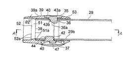
- Fig.10 (a) is a longitudinal cross-sectional view of the vertical direction which shows the state which attached the sleeve-shaped member to the female side edge part.
- FIG. 9B is a vertical longitudinal sectional view taken along line AA of FIG. 9A of a cylindrical pipe member having a male side end and a female side end constituting the pipe connection structure.
- FIG.9 (c) is the bottom view which looked at (
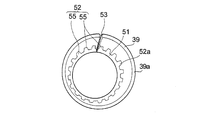
- FIG. 10B is a longitudinal cross-sectional view in the horizontal direction as viewed from below, taken along line AA in FIG. 10A, showing a state where a sleeve-like member is attached to the female side end.
- FIG. 11 is a perspective view illustrating another form of the insertion guide inclined portion when the inside of the sleeve-like member is viewed from the distal end side.
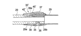
- FIG. 12 is a cutaway perspective view illustrating a situation in which the connection of the pipe member constituting the rod portion of the handle portion is released.
- Fig.13 (a) is a perspective view of the female side end part explaining the structure of the connection structure of another pipe.
- FIG. 13B is a vertical cross-sectional view in the vertical direction for explaining the configuration of another pipe connection structure.
- FIG. 14 is an exploded perspective view for explaining a main part of a handle with an end cap.
- Fig.15 (a) is a front view explaining the principal part of a handle
- FIG. 15B is a side view for explaining a main part of the handle with an end cap.
- FIG.15 (c) is a rear view explaining the principal part of a handle
- FIG.15 (d) is an end view explaining the principal part of the handle
- Fig.16 (a) is a perspective view explaining the cleaning tool provided with the pattern with an end cap.
- FIG.16 (b) is a perspective view explaining the cleaning tool provided with a pattern with an end cap.
- FIG. 17 is a perspective view of a main part for explaining the configuration of the joint structure of the cleaning head.
- FIG. 18 is an exploded perspective view of a main part for explaining the configuration of the joint structure of the cleaning head.
- FIG. 19 is an enlarged perspective view of a main part viewed from the direction A in FIG. 17 for explaining the configuration of the joint structure of the cleaning head.
- FIG. 20 is a partial cross-sectional view and a main part enlarged cross-sectional view illustrating the configuration of the joint structure of the cleaning head.
- FIG. 21A is a perspective view illustrating a situation where the handle is rotated in the circumferential direction with respect to the cleaning head.
- FIG. 21B is a perspective view illustrating a situation where the handle is rotated in the circumferential direction with respect to the cleaning head.
- FIG. 21C is a perspective view illustrating a situation where the handle is rotated in the circumferential direction with respect to the cleaning head.
- Fig.22 (a) is a perspective view explaining the condition which rotates a handle
- FIG. 22B is a perspective view illustrating a situation where the handle is rotated in the circumferential direction with respect to the cleaning head.
- FIG.22 (c) is a perspective view explaining the condition which rotates a handle
- FIG. 22D is a perspective view for explaining a situation where the handle is rotated in the circumferential direction with respect to the cleaning head.
- FIG. 22 (e) is a perspective view illustrating a situation where the handle is rotated in the circumferential direction with respect to the cleaning head.
- FIG. 22F is a perspective view illustrating a situation where the handle is rotated in the circumferential direction with respect to the cleaning head.
- FIG. 22G is a perspective view illustrating a situation where the handle is rotated in the circumferential direction with respect to the cleaning head.
- FIG. 23 is a perspective view of the cleaning head in a state before the cleaning sheet is attached.
- FIG. 24 is an exploded perspective view of the cleaning head.
- FIG. 25 is a plan view of the mounting member on which the cleaning sheet mounting tool is formed.
- Fig.26 (a) is a back view of the mounting member in which the cleaning sheet mounting tool was formed.
- FIG. 26B is an enlarged perspective view of a portion A in FIG.
- FIG. 27A is a bottom view of the cleaning tool main body illustrating another form of the corrugated uneven surface portion.
- FIG. 27B is a bottom view of the cleaning tool main body illustrating another form of the corrugated uneven surface portion.
- FIG. 27C is a bottom view of the cleaning tool main body illustrating another form of the corrugated uneven surface portion.
- FIG. 27D is a bottom view of the cleaning tool main body illustrating another form of the corrugated uneven surface portion.
- FIG. 27E is a bottom view of the cleaning tool main body illustrating another form of the corrugated uneven surface portion.
- FIG. 27F is a bottom view of the cleaning tool main body illustrating another form of the corrugated uneven surface portion.
- FIG. 28 is a cleaning sheet to which an adhering part is attached for explaining the state of adhering matter such as dust after performing a cleaning operation using the cleaning tool according to a preferred embodiment of the present invention.
- the cleaning tool of Patent Document 1 and the cleaning tool of Patent Document 2 have a curved shape of the cleaning surface of the lower surface of the cleaning tool body made of an elastic cushion material, so that dust and dirt can be easily taken in from the peripheral portion of the cleaning surface, By providing a large number of irregularities and corrugated ridges on the cleaning surface, it is possible to easily clean a surface to be cleaned that is not flat, and to easily scrape dirt on the surface to be cleaned.
- these cleaning tools and cleaning tools the above-described functions are effectively exhibited, but on the other hand, solids such as dust, hair, and dust are likely to remain in a partial region inside the cleaning surface. Therefore, the development of a new technology that makes it possible to efficiently clean the surface to be cleaned while adhering solid matter such as dust, hair, and dust to a wide area of the cleaning sheet that covers the cleaning surface. Is desired.
- a head side yoke portion provided in the cleaning head and a handle side yoke portion provided in the lower end portion of the handle are connected via a connecting member including a first rotating shaft portion and a second rotating shaft portion.
- the cleaning head rotates in the circumferential direction even when the handle is tilted over an angle range of considerable size from the state where the handle is erected vertically with respect to the cleaning head. It is possible to efficiently clean the floor surface etc. while the head side yoke part and the handle side yoke part are tilted further, for example in a state where the pattern is arranged substantially parallel to the cleaning head. And the rotational force from the handle is difficult to transmit to the joint part, and it becomes difficult to smoothly rotate the cleaning head in the circumferential direction.
- the handle when the cleaning head is inserted, the handle is arranged substantially parallel to the cleaning head, so that the floor around the bed leg, for example, surrounds the cleaning head. Since it becomes difficult to clean while rotating in the direction, new technology has been developed to smoothly rotate the cleaning head in the circumferential direction even when the cleaning head is inserted into such a low-height space. It is desired.
- a cleaning sheet made of non-woven fabric or the like is detachably attached to the cleaning tool body so as to cover the lower surface, which is the cleaning surface of the rectangular flat plate cleaning tool body, and dust or dirt is adhered to the cleaning sheet.
- Various cleaning tools have been developed so that only the cleaning sheet can be discarded (see, for example, Patent Document 6).
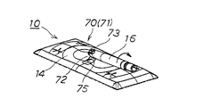
- the cleaning tool since the lower surface of the cleaning tool body is a stable mounting surface on the floor surface, the pattern is leaned against the wall surface while the cleaning tool body is mounted on the floor surface etc. In the state, the cleaning tool is stored or temporarily placed.
- the present invention is a cleaning that can efficiently clean a surface to be cleaned while adhering solid matter such as dust, hair, and dust to a wide area of a cleaning sheet that covers the cleaning surface of the cleaning tool body. Concerning ingredients.
- each pair of cylindrical pipes constituting the handle can be connected more smoothly, the engaging protrusion can be securely locked in the male side protrusion insertion hole, and
- the present invention relates to a cleaning tool including a pipe connection structure that makes it difficult for a mating protrusion to be removed from a male-side protrusion insertion hole.
- the present invention relates to a cleaning tool including a handle with an end cap for a cleaning tool that can effectively improve the stability when the handle of the cleaning tool is leaned against a wall surface or the like.
- the present invention makes it possible to smoothly rotate the handle in the circumferential direction around the joint even when the handle is arranged substantially parallel to the cleaning head, so that the handle can be operated from the handle even in a low or narrow space. It is related with the cleaning tool provided with the joint structure of the cleaning head which can be efficiently cleaned, rotating a cleaning head to the circumferential direction by.
- the present invention relates to a cleaning tool that can make it difficult to remove a cleaning sheet attached to a cleaning head and can further improve workability when the cleaning sheet is attached.
- the present invention includes a cleaning tool main body including a cleaning head, a base body attached to cover the lower surface of the cleaning head, and a handle portion attached to a surface opposite to the lower surface of the cleaning head, It is a cleaning tool that covers a cleaning surface by a lower surface of a base body and is attached with a cleaning sheet and wipes the surface to be cleaned with the cleaning sheet.
- the bottom surface of the base body has a corrugated cross-sectional shape in which a cross section in a direction perpendicular to the predetermined direction in which the cleaning is performed by the cleaning tool main body is alternately arranged in a crest and a trough.
- a corrugated surface is provided.
- the valley portion of the corrugated uneven surface portion is an oblique valley portion having an end portion opened to a side portion facing the predetermined direction of the base body and extending obliquely with respect to the predetermined direction. have.
- the front / rear, left / right, and upper / lower directions are defined, but this is defined for convenience in order to briefly explain the relative relationship of the components of the present invention.
- the direction at the time of manufacture and use is not limited.
- the handle portion is a handle, and the handle is preferably formed by connecting a plurality of cylindrical pipes by a pipe connecting structure that connects and integrates a pair of cylindrical pipes in the axial direction.
- the pipe connection structure is such that the male side end of one cylindrical pipe is inserted into the female side end of the other cylindrical pipe, and the male side projection insertion hole and the female side projection insertion hole are matched to each other from the outside. It is preferable that the engaging protrusion is locked and the sleeve-like member is attached so as to cover the joint portion between the male side end portion and the female side end portion from the outside.
- the female side end portion is provided with a positioning guide rib that protrudes inward from the inner peripheral surface of the female side end portion at a portion away from the female side protrusion insertion hole in the circumferential direction, and the male side
- the end portion is provided with a guide groove corresponding to the positioning guide rib extending in the axial direction from the distal end edge portion of the male side end portion at a portion away from the male side protrusion insertion hole in the circumferential direction.
- the male side projection insertion hole is aligned with the female side projection insertion hole while the positioning guide rib of the female side end portion is locked and guided in the guide groove of the male side end portion. It is preferable that an end is inserted into the female side end.
- the handle portion is a handle, and the handle is preferably formed by connecting a plurality of cylindrical pipes by a pipe connecting structure that connects and integrates a pair of cylindrical pipes in the axial direction.
- the pipe connection structure is such that the male side end of one cylindrical pipe is inserted into the female side end of the other cylindrical pipe, and the male side projection insertion hole and the female side projection insertion hole are matched to each other from the outside. It is preferable that the engaging protrusion is locked and the sleeve-like member is attached so as to cover the joint portion between the male side end portion and the female side end portion from the outside.
- the sleeve-like member is provided with a contact rib that protrudes inward from the inner peripheral surface of the portion covering the joint portion and that the end surface of the female side end portion contacts from the rear side continuously or intermittently in the circumferential direction.
- the contact rib is provided with an insertion guide inclined portion extending obliquely outward in the radial direction toward the distal end side of the sleeve-like member, continuously or intermittently provided in the circumferential direction, With the end face abutting against the abutment surface of the abutment rib and the sleeve-like member attached to the female end of the other cylindrical pipe, the male end of the one cylindrical pipe is It is preferable that the insertion guide is inclined and inserted into the female side end.
- the handle portion is a handle, and an end cap is preferably attached to the upper end of the handle.
- the end cap is made of an elastic material, and is attached to the upper end portion of the handle via a mounting hole, and a covering end surface arranged to cover the end surface portion of the handle is perpendicular to the central axis direction of the handle.
- the tapered tip end edge portion of the end cap is a cushion that can be elastically deformed inward and outward in the radial direction centered on the central axis direction of the handle It is preferable to form the part.
- the handle portion is a handle, and includes a joint structure of a cleaning head that allows the handle to be rotated 360 degrees in a circumferential direction around the joint portion in a state where the handle is disposed substantially parallel to the cleaning head.
- the cleaning head joint structure has a bifurcated head-side yoke portion protruding from the upper surface of the cleaning head and a bifurcated handle-side yoke portion provided at the lower end of the handle, the central axis of which is It is preferable that the joint portion that is rotatable in the vertical direction and the circumferential direction is formed by connecting via a connecting member that includes a first rotation axis portion and a second rotation axis portion that are orthogonal to each other. .
- Each of the opposing surfaces arranged with a gap between the pair of yoke protrusions constituting the head side yoke portion has a symmetrical mountain-shaped outer peripheral edge portion having inclined portions on both sides of the top portion, and
- the pair of yoke pieces constituting the side yoke portion has a width that is substantially the same as the interval width between the opposing surfaces of the pair of yoke protrusions, and the handle is disposed in a state substantially parallel to the cleaning head. It is preferable that the side edge portion of any one of the yoke pieces can be brought into contact with the outer peripheral edge portion of the facing surface of any one of the yoke protrusions.
- the side edge of one of the yoke pieces becomes the opposite surface of one of the yoke protrusions. It is preferable that the vehicle can be moved along the outer peripheral edge of the frame or by sliding down.
- the state in which the handle is disposed substantially parallel to the cleaning head is a state in which the handle is disposed substantially parallel to the cleaning surface of the cleaning head.
- a state in which the handle extends in parallel with the cleaning surface of the cleaning head for example, a state in which the handle extends obliquely at a gentle inclination angle of about 10 to 20 degrees with respect to the cleaning surface of the cleaning head. included.
- a cleaning sheet mounting tool for mounting the cleaning sheet in a removable manner is provided on the upper surface of the cleaning head, and the edge of the cleaning sheet wrapped around the bottom surface of the cleaning head is attached to the cleaning sheet mounting tool.
- the cleaning sheet mounting tool is configured by forming a holding slit and an opening slit in a mounting member, and the holding slit is in a direction perpendicular or substantially perpendicular to a direction of a tensile force acting on the cleaning sheet.
- the opening slit is formed in a sawtooth shape or a corrugated shape, and the opening slit is continuous with the holding slit at the center of the holding slit, and is provided on one side of the holding slit. It is composed of two slits extending and an oblique slit extending obliquely with respect to the extending direction of the holding slit on the other side, and the oblique slit is a proximal end portion adjacent to the holding slit And a wide portion having a slit width wider than the base end portion on the distal end side with respect to the base end portion.
- a cleaning tool 10 according to a preferred embodiment of the present invention shown in FIG. 1 covers a cleaning surface 12 of a cleaning tool body 11 and a disposable cleaning sheet 13 is attached so as to be detachable and replaceable. It is used when cleaning work.
- the cleaning tool 10 of this embodiment wipes the surface to be cleaned by the cleaning tool main body 11, the cleaning tool 13 covers the cleaning surface 12 of the cleaning tool main body 11, particularly solids such as dust, hair, and dust.
- a function is provided that allows the surface to be cleaned to be cleaned while adhering to a specific area.
- the cleaning tool 10 of the present embodiment includes a cleaning head body 11 including a cleaning head 14 and an elastically deformable base body 15 attached to cover the lower surface of the cleaning head 14, and the opposite side of the lower surface of the cleaning head 14. And a handle portion 16 attached to the surface of the base body 15.
- a cleaning sheet 13 is mounted to cover the lower surface (cleaning surface 12) of the base body 15, and the surface to be cleaned is wiped off by the cleaning sheet 13.
- the lower surface of the base body 15 has a predetermined direction X in which the cleaning tool body 11 performs cleaning, and the base body 15.
- the corrugated uneven surface portion 19 has a corrugated cross-sectional shape in which the cross-section in the vertical direction in the vertical direction (right-angle direction) Y in plan view of the lower surface of FIG. ing.
- the valley portion 18 of the corrugated uneven surface portion 19 has an end opened to a side portion 15a opposite to the predetermined direction X of the base body 15, and extends obliquely with respect to the predetermined direction X to be cleaned.
- the adhering matter dust such as cotton dust, solid matter such as hair and dust
- to the sheet 13 is guided along the surface of the cleaning sheet 13 in an oblique direction while adhering to the cleaning sheet 13 along with wiping of the surface to be cleaned.
- An oblique guide portion (oblique valley portion) 18a that can be used is provided. Further, at the peak portion 17 of the corrugated uneven surface portion 19, a protruding rib 20 protruding from the top portion 17 a of the peak portion 17 extends at least in a portion along the diagonal guide portion (oblique valley portion) 18 a of the valley portion 18. It is preferable that a plurality are provided at intervals in the installation direction.
- the predetermined direction X in which cleaning is performed by the cleaning tool main body 11 is a direction (cleaning direction) in which the cleaning tool main body 11 can be efficiently cleaned, and the user of the cleaning tool 10 is the place where the cleaning is performed.
- the direction can be selected according to the situation.
- the direction X orthogonal to the long side portion 15a of the base body 15 having a rectangular planar shape will be described as the cleaning direction.
- the direction Y perpendicular to the direction can be the cleaning direction.
- the oblique guide portion 18a is a corrugated uneven surface portion that can guide the adhered matter to the cleaning sheet 13 in an oblique direction along with the wiping of the surface to be cleaned, toward the central direction of the base body 15. It refers to 19 valleys 18 and is also an oblique valley and an oblique groove.
- the corrugated uneven surface portion 19 on the lower surface of the base body 15 is provided as a part of the uneven surface spreading in a ripple pattern on the entire surface of the base body 15.
- the surface is an uneven surface that extends in a circular shape over the entire surface of the base body 15.
- the cleaning head 14 constituting the cleaning tool main body 11 has a rectangular planar shape having a long side of about 200 to 300 mm and a short side of about 50 to 150 mm. It is a flat plate member made of plastic.
- the peripheral portion of the top surface portion 14a of the cleaning head 14 is bent downward to form a peripheral wall portion 14b.
- a plurality of reinforcing ribs 21 project downward from the top surface portion 14a across the hollow portion. Is provided.
- a handle support joint portion 22 is integrally provided on the upper surface of the top surface portion 14a of the cleaning head 14, which is the surface opposite to the lower surface that is the opening surface of the cleaning head 14, a central portion thereof is raised, and a handle support joint portion 22 is integrally provided. ing.
- the handle support portion 22 is joined to the cleaning tool body 11 not only in the vertical direction but also in the left-right direction by joining the rotary joint portion 23 provided at the lower end portion of the handle portion 16 to the handle support joint portion 22 in a rotatable manner. Further, it is possible to perform the cleaning work with the cleaning tool 10 while rotating the lens.
- the top surface portion 14a of the cleaning head 14 is provided with a known sheet holding portion 24 made of a flexible elastic material having an engagement slit 24a or a cleaning sheet mounting tool 24 as a sheet holding portion 24 described later. ing.
- the cleaning sheet 13 is wound around the cleaning head 14 so as to cover the lower surface (cleaning surface 12) of the base body 15 attached integrally to the lower surface side of the cleaning head 14 from below, the end of the cleaning sheet 13 is The cleaning sheet 13 can be easily attached to the cleaning tool main body 11 so as to be attachable / detachable by being pushed into and engaged with the engaging slit 24a of the sheet holding portion 24 provided on the top surface portion 14a (see FIG. 1). .
- the base body 15 constituting the cleaning tool main body 11 together with the cleaning head 14 is made of, for example, urethane, EVA (ethylene vinyl acetate copolymer) resin, or the like as an elastically deformable synthetic resin material.
- the base body 15 has a rectangular planar shape that is slightly larger than the cleaning head 14.
- the base body 15 includes a bottom surface portion 15c and a peripheral wall portion 15d provided on the peripheral edge portion of the bottom surface portion 15c.
- the bottom surface portion 15c is formed with a thin thickness of about 0.5 to 3 mm, for example.
- the peripheral wall portion 15d has a substantially triangular cross-sectional shape.
- a concave fitting portion 15e into which the cleaning head 14 is fitted is formed on the upper surface side of the base body 15 surrounded by the four peripheral wall portions 15d.
- the cushioning material 25 is interposed between the lower surface of the cleaning head 14 and the bottom surface portion 15c of the base body 15, and the cleaning head 14 is fitted into the recessed fitting portion 15e to perform cleaning.
- the cleaning tool main body 11 in which these are integrated is formed.
- the cushion material 25 interposed between the lower surface of the cleaning head 14 and the base body 15 is made of, for example, a sponge (the material is, for example, urethane foam) as a softer cushion material than the base body 15.
- the cushion material 25 includes an upper sponge material 25a having a rectangular planar shape that is substantially the same size as the recessed fitting portion 15e of the base body 15, and a lower sponge material having a rectangular planar shape that is slightly smaller than this. 25b.
- the cushion material 25 fills a gap between the plurality of reinforcing ribs 21 provided on the lower surface side of the cleaning head 14 and the bottom surface portion 15c of the base body 15 in a state where these sponge materials 25a and 25b are overlapped. In this manner, the cleaning head 14 is mounted over substantially the entire lower surface.
- the cleaning tool main body 11 Since the cushioning material 25 is interposed between the lower surface of the cleaning head 14 and the bottom surface portion 15c of the base body 15, the cleaning tool main body 11 is formed, whereby the bottom surface portion 15c of the base body 15 is formed by the cushion material 25. It is possible to extrude in a state where it is supported in a planar shape from the back side. In addition, the bottom surface of the bottom surface portion 15c serving as the cleaning surface 12 can be projected downward into a curved shape that gently curves through the soft elastic biasing force of the cushion material 25 (FIG. 5). reference).
- the cushion member 25 can be easily balanced in an overall manner. While being crushed and accompanied by a soft cushion feeling, the lower surface of the base body 15 covered with the cleaning sheet 13 can be a flat surface that fits the surface to be cleaned 50 over a wide range.
- the cushion material 25 interposed between the lower surface of the cleaning head 14 and the bottom surface portion 15c of the base body 15 is a softer cushion material than the base body 15, and is a flat material in which, for example, air or liquid is sealed in addition to sponge.
- a simple bag or the like can also be used.
- the peripheral wall portion 15 d constituting the peripheral portion of the base body 15 has a substantially triangular cross-sectional shape, so that the outer peripheral portion of the base body 15 has an acute angle with respect to the lower surface of the base body 15. A tapered surface.
- the cleaning operation is effectively performed while the outer peripheral edge of the base body 15 is brought into contact with the wall surface, for example, against the floor surface at the corner portion of the wall surface and the floor surface or the floor surface at the corner portion of the wall surface. It becomes possible to do.
- the cleaning sheet 13 that covers the cleaning surface 14 and is attached to the cleaning tool main body 11 and adheres dust, dirt, and the like for example, various known cleaning sheets such as olefin-based ultrafine fiber nonwoven fabrics are used. Can be used.
- the cleaning tool main body 11 cleans the lower surface of the bottom face part 15c of the base body 15 by predetermined.
- the cross section in the vertical direction in the direction X and the vertical direction (perpendicular direction) Y in plan view of the lower surface of the base body 15 is a waveform cross-sectional shape in which peaks 17 and valleys 18 are alternately arranged.
- the corrugated uneven surface portion 19 is provided.
- the base body 15 has a rectangular planar shape, and the predetermined direction X that can be efficiently cleaned by the cleaning tool body 11 is the short side portion of the base body 15 (cleaning tool body 11).
- the predetermined direction X by the cleaning tool body 11 and the direction Y perpendicular to the lower surface of the base body 15 in plan view are the long sides of the base body 15 (cleaning tool body 11).
- the direction is along 15a.
- the corrugated uneven surface portion 19 is configured as a part of a rippled uneven surface extending in a circular shape from the center portion of the base body 15.
- a rippled uneven surface is formed on substantially the entire surface of the lower surface of the base body 15 except for the four corners.
- a region sandwiched between the sixth valley portion 18 and the tenth valley portion 18 from the central portion of the ripple-shaped uneven surface is such that an end portion of these valley portions 18 opens into the long side portion 15 a of the base body 15.
- the corrugated uneven surface portion 19 is formed (see FIGS. 2A and 2B).
- a pair of corrugated concave and convex surface portions 19 are disposed on both sides in the direction of the long side portion 15 a across the center portion of the base body 15.
- each trough 18 in the corrugated uneven surface portion 19 is a cleaning tool while being curved in an arc shape from the end opening to the long side portion 15a of the base body 15 toward the center line C in the short direction of the base body 15. It extends obliquely with respect to a predetermined direction X in which cleaning is performed by the main body 11, and its substantially entire length is used for wiping the object to be cleaned (solid matter such as dust, hair, and dust) on the cleaning sheet 13.
- an oblique guiding portion (oblique valley) 18 a that can be guided obliquely along the surface of the cleaning sheet 13.
- the valley portion 18 of the corrugated uneven surface portion 19 has a width of about 2 to 10 mm, for example, and a substantially arc cross section having a depth of about 0.5 to 3 mm, for example, from the top portion 17a of the peak portion 17. It is formed as a groove having a shape. Further, the valley portions 18 of the corrugated uneven surface portion 19 are arranged concentrically with the central portion of the base body 15 as the center, and five on each side of the long side portion 15a across the central portion, a total of ten. Is provided. Further, the valley portion 18 of the corrugated uneven surface portion 19 is provided with a spread angle ⁇ 1 (see FIG.
- the spread angle ⁇ 1 is an angle between the tangent line in contact with the valley 18 and the cleaning direction X when the valley 18 is arcuate.
- the spread angle of the oblique guide part (oblique valley part) 18a is the angle concerned, so that the adhering matter adheres to the surface of the cleaning sheet 13 along the oblique guide part (oblique valley part) 18a during cleaning. Therefore, efficient cleaning using the entire cleaning sheet 13 becomes possible.
- the ridges 17 and the valleys 18 of the corrugated uneven surface portion 19 are arranged symmetrically across the short direction center line C of the base body 15.
- the cleaning tool main body 11 is moved not only to wipe the surface to be cleaned while moving the cleaning tool main body 11 to the front side in the predetermined direction X but also to the rear side in the predetermined direction (cleaning direction) X.
- cleaning direction cleaning direction
- solid matter such as dust is applied to a wide area on the surface of the cleaning sheet 13. It becomes possible to adhere.
- the front and rear can be appropriately switched, and solid matter such as dust can be more efficiently attached.
- the lower surface of the base body 15 has a plurality of circular ring-shaped peaks 17 ′′ and valleys 18 ′′ arranged concentrically at the central portion sandwiched between the corrugated uneven surface portions 19 on both sides.
- a center corrugated uneven surface portion 19 ′′ is formed as a part of the rippled uneven surface portion.
- Each valley portion 18 ′′ of the central corrugated uneven surface portion 19 ′′ has an end on the long side portion 15a of the base body 15. It is a closed annular ring shape without opening.
- the portion overlapping the peripheral wall portion 15d having a substantially triangular cross-sectional shape of the base body 15 has a valley portion 18 ′ of the auxiliary corrugated uneven surface portion 19 ′ to be described later.
- a deep groove portion 26 formed by further deeply cutting the bottom portions of the valley portions 18, 18 ′, 18 ′′ including the portion overlapping the peripheral wall portion 15 b is provided.
- the said deep groove part 26 shows that a distortion
- the valley portion 18 that is curved and extends obliquely in an arc shape has a substantially full length as an oblique guide portion (oblique valley portion) 18 a, so that at least the valley portion 18 of each mountain portion 17.
- a plurality of protruding ribs 20 are provided over substantially the entire length of the mountain portion 17 as a portion along the oblique guide portion (oblique valley portion) 18a.
- the plurality of protruding ribs 20 protrude from the top portion 17a of each peak portion 17, and are provided in a plurality of intervals in the extending direction of the top portion 17a, for example, about 2 to 10 mm.
- the projecting rib 20 is preferably a crest that is perpendicular (perpendicular) in a plan view of the extending direction of the oblique guide portion (oblique valley portion) 18a of the valley portion 18 and the lower surface of the base body. 17 is a linear rib piece 20a provided in the width direction.
- the protruding rib 20 is a linear rib piece 20 a provided in the width direction of the peak portion 17, a portion of the surface of the cleaning sheet 13 that contacts the peak portion 17 with wiping of the surface to be cleaned
- the adhering matter sandwiched between the surfaces to be cleaned or the adhering matter on the surface of the cleaning sheet 13 in the vicinity of the portion in contact with the protruding rib 20 is diffused in the direction of the adjacent valley portion 18 and the valley portion 18 is obliquely guided.
- the protruding rib 20 has a function of further facilitating adhesion of dirt and dust on the surface to be cleaned to the cleaning sheet 13 by a scraping effect.
- the cleaning tool 10 of the present embodiment has a linear rib piece 20a provided obliquely with respect to the predetermined direction X.
- adhering matter such as dust easily diffuses over the entire surface of the cleaning sheet 13 as the surface to be cleaned is wiped, and dirt, dust, etc. on the surface to be cleaned Is more easily attached to the cleaning sheet 13.
- the height of the protruding rib 20 (the distance from the top of the peak portion 17 to the top of the protruding rib 20) is the surface to be cleaned. From the viewpoint that dust and the like can be removed and can be diffused over a wide range while adhering to the cleaning sheet 13, 0.3 to 1 mm is preferable, and 0.4 to 0.7 mm is more preferable.
- the depth of the valley portion 18 (the distance from the top of the mountain portion 17 to the deepest portion of the valley portion 18) is preferably 0.7 to 3 mm, and more preferably 0.8 to 2 mm.
- the height of the protruding rib 20 is preferably smaller than the depth of the valley portion 18.
- a plurality of protruding ribs 20 ′′ are also provided in the width direction of the peak portion 17 ′′ on the plurality of annular ring-shaped peak portions 17 ′′ of the central corrugated uneven surface portion 19 ′′.
- a plurality of protrusions 20 ′′ projecting from the peak 17a ′′ of each peak 17 ′′ are provided at intervals in the extending direction of the peak 17a ′′.
- the peak portions 17 and 17 ′′ of the corrugated uneven surface portion 19 and the central corrugated uneven surface portion 19 ′′ configured by the uneven surface spreading in a circular ripple shape from the central portion of the base body 15 are the top portions 17a.
- 17a ′′ is preferably gradually or gradually widened from the top portion of the outer circular arc surface to the peak portions 17, 17 ′′ on the center side. Accordingly, it is preferable that at least the top portion 17 a ′′ of the peak portion 17 ′′ at which the handle portion 16 is connected to the cleaning head 14 is a flat top portion having a considerable width.
- the cleaning portion 12 can be pressed against the surface to be cleaned from the handle portion 16 to perform the cleaning operation.
- the pressing load is stably supported in a wide area by the planar top portion 17a "at the central portion in the vicinity of the handle portion 16 where a large pressing load is applied. This makes it possible to effectively avoid the central portion of the valley portion 18 ′′ from being easily crushed.
- the handle portion 16 leads to the cleaning tool body 11.
- the entire lower surface of the base body 15 can be made flat.
- the vertical cross section in the predetermined direction X in which cleaning is performed by the cleaning tool main body 11 is formed at the four corners on the lower surface of the base body 15 with the peak portion 17 ′ and the valley portion.
- the auxiliary corrugated concave / convex surface portion 19 ′ has a corrugated cross-sectional shape in which 18 ′ and alternately are continuously arranged.
- each auxiliary corrugated uneven surface portion 19 ′ is provided with four trough portions 18 ′ extending in a semicircular shape so as to be concentrically arranged around each corner portion.
- Each valley portion 18 ′ has one end opened to the rectangular planar short side portion 15 b of the base body 15, and the other end opened to the rectangular planar long side portion 15 a of the base body 15. Yes. Since each valley portion 18 'extends in a semicircular shape, an auxiliary oblique guide portion (auxiliary oblique valley portion) 18a' whose substantially entire length extends obliquely with respect to the short side portion 15b in a curved state. It has become.
- the portion sandwiched by the adjacent valley portions 18 ′ in the auxiliary corrugated uneven surface portion 19 ′ is a ridge portion 17 ′.
- the substantially entire length of the valley portion 18 ′ is the auxiliary oblique guide portion (auxiliary oblique valley portion) 18a ′
- a plurality of projecting ribs 20 ′ are provided over substantially the entire length of the peak portion 17 ′ as a portion along the (slanted valley portion) 18a ′.
- Each of the plurality of protruding ribs 20 ′ is preferably a line provided in the extending direction of the valley portion 18 ′ and the width direction of the peak portion 17 ′ that is perpendicular (right angle) when the lower surface of the base body 15 is viewed in plan view. It is a rib piece.
- the plurality of projecting ribs 20 ′ are provided in a projecting manner from the top portions 17 a ′ of the crest portions 17 ′ and provided in the extending direction of the top portions 17 a ′ at intervals of about 2 to 10 mm, for example.
- a trough portion 18 ′ that extends obliquely with respect to the short side portion 15 b is provided.
- a predetermined direction X by the cleaning tool body 11 and a direction Y perpendicular to the lower surface of the base body 15 in plan view are set as the cleaning direction.
- the cleaning sheet 13 covering the surface 12 can be attached to a wide area.
- the valley portion 18 ′ of the auxiliary corrugated uneven surface portion 19 ′ is cleaned in the predetermined direction X by the cleaning tool main body 11 because the other end portion is open to the long side portion 15 a of the base body 15. Even when the work is performed, deposits due to solids such as dust are caused by the projecting ribs 20 ′ of the valley portions 18 ′ and the peak portions 17 ′ together with the projecting ribs 20 of the valley portions 18 and the peak portions 17 of the corrugated uneven surface portion 19. It is possible to guide and adhere to a wider area of the cleaning sheet 13 covering the cleaning surface 12.
- steering-wheel 16 is provided as a handle
- FIG. The handle 16 as the handle portion includes a grip portion 27 at the upper end portion, and a handle main body 28 interposed between the cleaning head 14 and the grip portion 27.
- the handle main body 28 connects the plurality of cylindrical pipes 29 in the axial direction via a connecting portion by a connecting structure 30 described later, so that the entire handle portion 16 including the gripping portion 27 performs a cleaning operation. For example, it is assembled so as to have a length of about 100 to 150 cm.
- a rotary joint portion 23 is provided at the lower end portion of the handle body 28.
- the handle portion 16 is moved up and down with respect to the cleaning tool body 11 by rotatably joining the rotary joint portion 23 to the handle support joint portion 22 provided on the top surface portion 14 a of the cleaning head 14. It can be rotated in the direction and the left-right direction.
- a grip portion 27 is detachably attached to the upper end portion of the handle body 28 via a joint portion 31 having a configuration substantially similar to a cylindrical pipe connection structure 30 described later.
- the grip portion 27 is a molded article made of, for example, ABS (acrylonitrile butadiene styrene) resin, and has a substantially cylindrical shape with a thickness and an outer shape that can be easily gripped by hand as shown in FIG.
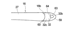
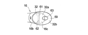
- a non-slip end member 32 made of, for example, EVA (ethylene vinyl acetate) resin as a soft material is integrally attached to the upper end portion of the grip portion 27 as an end cap. Since the end cap 32 is attached to the upper end portion of the gripping portion 27, as will be described later, for example, when the cleaning tool 10 is leaned against the wall surface, the friction between the upper end portion of the gripping portion 27 contacting the wall surface and the wall surface.
- the end surface of the end cap 32 is cut, molded, or the like obliquely so as to be a tapered surface 32a that is an inclined surface, whereby the upper end portion of the grip portion 27 is brought into contact with the wall surface in a stable state, The frictional force can be further improved.
- a joint portion 31 for connecting the handle body 28 is provided at the lower end portion of the grip portion 27.
- the joint portion 31 includes an end sleeve portion 33 into which the uppermost cylindrical pipe 29 constituting the handle body 28 is inserted, an annular belt groove 34 formed by cutting out the outer peripheral surface of the lower end portion of the grip portion 27, A notch ring member 35 having an engagement protrusion 36 on the peripheral surface, a button member 37 attached to the notch portion 35a of the notch ring member 35, and the like.
- the joint part 31 is in a state in which the reduced diameter male side end 29a of the cylindrical pipe 29 of the handle body 28 is inserted into the end sleeve part 33 by a detachable structure that is substantially the same as the pipe connection structure 30 described later.
- the handle body 28 is detachably connected.
- the handle body 28 of the handle 16 is formed by connecting a plurality of cylindrical pipes 29 by a pipe connecting structure 30 that connects and integrates a pair of cylindrical pipes 29 in the axial direction. That is, the cleaning tool 10 is disassembled into parts such as a cleaning head 14 and a cylindrical pipe 29 for convenience of transportation and sales, and these parts are put into a product in a state of being put together. Assemble and use.
- the pipe connection structure 30 of the present embodiment smoothly connects each pair of cylindrical pipes 29 when a plurality of cylindrical pipes 29 are connected and integrated in the axial direction to form the handle body 28 of the handle 16. Make it possible.
- the pipe connection structure 30 is an engagement that is inserted and locked from the outside into the male-side protrusion insertion hole 43c and the female-side protrusion insertion hole 43b that are matched to connect and integrate each pair of cylindrical pipes 29.
- the protrusion 36 (see FIG. 8C) has a function of making it difficult to remove from the male-side protrusion insertion hole 43c when the cleaning tool 10 is used so that the cleaning operation can be performed in a more stable state.
- the pipe connection structure 30 is formed by connecting the male side end portion 29a of one cylindrical pipe 29 of the pair of cylindrical pipes 29 to the other. Even when the male side end portion 29a is inserted into the female side end portion 29b while the center axes thereof are displaced when inserted into the female side end portion 29b of the cylindrical pipe 29, the position of such a central axis. By correcting the displacement, the male side end portion 29a has a function that can effectively avoid the end face of the male side end portion 29b from interfering with the end face of the female side end portion 29b.
- the pipe connection structure 30 is formed by replacing the male side end 29a of one cylindrical pipe 29 with the female side end 29b of the other cylindrical pipe 29.
- the engagement projection 19 is locked from the outside by matching the male side projection insertion hole 43c and the female side projection insertion hole 43b, and the joint portion between the male side end portion 29a and the female side end portion 29b. 50, the sleeve-like member 39 is attached from the outside, and as shown in FIGS. 9 (a) to 9 (c), a female-side projection 29 is inserted into the female-side end 29b.
- Positioning guide ribs 42 projecting inward from the inner peripheral surface of the female side end portion 29b are provided at a portion away from the hole 43b in the circumferential direction, and the male side end portion 29a corresponds to the positioning guide rib 42.
- the guide groove 45 which extends axially from the leading edge of the male side end portion 29a is provided. While the positioning guide rib 42 of the female side end portion 29b is locked and guided in the guide groove 45 of the male side end portion 29a, the male side end portion until the male side projection insertion hole 43c matches the female side projection insertion hole 43b. 29a is inserted into the female end portion 29b.
- the positioning guide rib 42 is provided in a portion away from the female side projection insertion hole 43b in the circumferential direction and on the opposite side in the radial direction from the female side projection insertion hole 43b. , Apart from the male side projection insertion hole 43c in the circumferential direction, it is provided in a portion opposite to the male side projection insertion hole 43c in the radial direction.
- the male side end portion 29 a is an end portion of one cylindrical pipe 29 whose diameter is reduced.
- the positioning guide rib 42 protrudes from the inner surface of the sleeve-like member 39 and is provided integrally with the sleeve-like member 39, and the sleeve-like member 39 is attached to the female side end portion 29b.
- the positioning guide rib 42 protrudes from the inner surface of the sleeve-like member 39 and is provided integrally with the sleeve-like member 39, and the sleeve-like member 39 is attached to the female side end portion 29b.
- the pipe connection structure 10 includes a portion covering the joint portion 50 in the sleeve-like member 39, as shown in FIGS. 8 (a) to 8 (c), 10 (a), and 10 (b).
- An annular abutment rib 51 that protrudes inward from the inner circumferential surface of the female side end 29b and abuts the end surface of the female side end portion 29b from the rear is provided continuously or intermittently in the circumferential direction (in FIG.
- the contact rib 51 is provided in an annular shape provided continuously in the circumferential direction and partly cut away in the circumferential direction). Extending from the contact surface 51a (see FIGS.
- the insertion guide inclined portion 52 is continuously or intermittently provided in the circumferential direction (in FIG. 8A and the like, continuous in the circumferential direction). And it shows a case where provided).
- the end surface of the female side end portion 29b is brought into contact with the contact surface 51a of the contact rib 51 so that the female side end portion 29b of the other cylindrical pipe 29 is contacted.
- the male side end portion 29a of one cylindrical pipe 29 is guided by the insertion guide inclined portion 52 as shown in FIGS. 8 (a) to 8 (c). It is inserted into the female side end portion 29b.
- the male side end portion 29 a is an end portion of one cylindrical pipe 29 whose diameter is reduced.
- the handle body 28 includes a handle 16 including a grip portion 27 by connecting a plurality of cylindrical pipes 29 made of, for example, an aluminum alloy or ABS (acrylonitrile butadiene styrene) resin in the axial direction via a pipe connecting structure 30.
- a pipe connecting structure 30 made of, for example, an aluminum alloy or ABS (acrylonitrile butadiene styrene) resin in the axial direction via a pipe connecting structure 30.
- a pipe connecting structure 30 are assembled so as to have a length of, for example, about 100 to 150 cm suitable for performing a cleaning operation.
- the lower end of the handle body 28 is rotatably connected to the cleaning head 14 via the rotary joint 23 (see FIG. 1).
- the pair of cylindrical pipes 29 and 29 of the plurality of cylindrical pipes 29 constituting the handle main body 28 are each connected in the axial direction via a connecting portion having a pipe connecting structure 30. Integrated. That is, in the present embodiment, as shown in FIGS. 8 (a) to 8 (c), the connecting portion is connected to the reduced-diameter male end portion 29a of one cylindrical pipe 29 with the other cylindrical pipe 29.
- the female side end 29b is inserted into the pipe insertion opening 38, the male side projection insertion hole 43c and the female side projection insertion hole 43b are aligned, the engagement projection 36 is inserted and locked from the outside, and the male side end
- the sleeve portion 39 is attached by covering the joint portion 50 between the portion 29a and the female end portion 29b from the outside.
- the sleeve-like member 39 includes a sleeve main body 39a, a notch ring member 35, and a button member 37 as shown in FIG.
- the sleeve-like member 39 is a hollow cylindrical member having an inner diameter substantially the same as the outer diameter of the cylindrical pipe 29, and has openings at both ends. Since the intermediate portion in the axial direction is formed thicker than the vicinity of the opening, the intermediate portion in the axial direction has an outer peripheral surface shape that rises smoothly.
- An annular belt groove 40 extending in the circumferential direction is formed in the raised axial intermediate portion of the sleeve-like member 39 by cutting the outer peripheral surface into a belt groove shape. As will be described later, a notch ring member 35 and a button member 37 are attached to the annular belt groove 40.
- a sleeve projection insertion hole 43a is formed in the annular belt groove 40 of the sleeve body 39a.
- An engagement protrusion 36 provided integrally with the notch ring member 35 is inserted and attached to the sleeve protrusion insertion hole 43a.
- the sleeve main body 39a is formed with a cut 53 extending in the axial direction of the sleeve-like member 39 so as to cross the central portion of the sleeve projection insertion hole 43a.
- annular contact rib 51 is provided integrally with the sleeve body 39a.
- the abutment rib 51 preferably protrudes slightly inward (inner diameter side) at the same height as the thickness of the end face of the female side end 29b of the other cylindrical pipe 29.
- the sleeve-like member 39 is attached to the female side end portion 29b by bringing the end surface of the female side end portion 29b into contact with the flat contact surface 51a formed on the rear end side of the sleeve main body 39a of the contact rib 51.
- the contact rib 51 is inclined radially outward from the portion opposite to the contact surface 51a with the female end portion 29b toward the distal end side of the sleeve-like member 39.
- an insertion guide inclined portion 52 extending.
- the insertion guide inclined portion 52 is provided such that the inclined surface 52a is linearly inclined radially outward at an inclination angle of preferably 10 to 30 degrees with respect to the axial direction of the sleeve-like member 39. ing.
- the positioning guide rib 42 is integrally provided on the inner peripheral surface of the sleeve main body 39a so as to protrude inward from a position opposite to the sleeve projection insertion hole 43a in the radial direction (see FIG. 8 (a) to FIG. 8 (c) and FIG. 10 (a)).
- the positioning guide rib 42 is a substantially rectangular plate-like rib extending in the axial direction of the sleeve main body 39 a, and the sleeve main body 39 a is connected to the female end portion 29 b of the other cylindrical pipe 29. Is inserted and locked in the positioning locking hole 44 formed in the female side end portion 29b, and protrudes inward from the inner peripheral surface of the female side end portion 29b.
- the notch ring member 35 and the button member 37 are attached to the annular band groove 40 of the sleeve main body 39a.
- a sleeve-like member 39 is formed.
- the sleeve main body 39a is elastically deformed so as to expand the notch 53 and expand the diameter, thereby inserting and locking the positioning guide ribs 42 into the positioning locking holes 44 formed in the female side end portion 29b. Attached to the end 29b. Further, by this, the sleeve projection insertion hole 43a is arranged so as to match the female side projection insertion hole 43b of the female side end portion 29b.
- the notch ring member 35 is formed in a substantially ring-shaped band plate shape having a width similar to the annular band groove 40 of the sleeve main body 39 a, which is curved so as to have an arc shape exceeding a semicircle.
- An engaging projection 36 is provided integrally as a member that protrudes inward from the inner peripheral surface of the central portion facing the notch 35a.
- a leg locking groove 35b is formed in the inner surface of a portion of the notch ring member 35 that is continuous with the notch 35a so as to extend from the notch 35a in the circumferential direction.
- the notch ring member 35 pushes and expands the notch portion 35a to be elastically deformed, and the engaging projection 36 is inserted into the sleeve projection insertion hole 43a of the matched sleeve main body 39a and the female side projection insertion hole 43b of the female side end portion 29b.
- the sleeve body 39a is mounted so as to be fitted from the outside into the annular band groove 40.
- the distal end portion of the engagement protrusion 36 is formed so that the tapered surface 36a provided at the distal end portion faces the pipe insertion opening 38 side of the female side end portion 29b and the female side end of the other cylindrical pipe 29.
- the portion 29b is disposed so as to protrude inward from the inner peripheral surface (see FIGS. 8A and 9A).
- the notch ring member 35 functions as an elastic portion that is deformed radially outward by a pressing operation from the button member 37 and generates a biasing force radially inward, and is integrated therewith. With the engagement protrusion 36 pressed from the outside, the engagement protrusion 36 is protruded inward from the inner peripheral surface of the sleeve-like member 39.
- the button member 37 is, for example, a molded product made of plastic having an elliptical flat surface shape whose outer peripheral surface is a gently convex curved surface (see FIG. 9C), and is integrally formed from side edges on both sides. A pair of extended extrusion legs 37a are provided (see FIG. 7).
- the button member 37 engages the pushing leg portions 37a with the leg engaging grooves 35b on both sides of the notched portion 35a of the notched ring member 35, and the annular belt groove 40 in the region of the notched portion 35a. Is mounted in a state where a gap 47 is held with the annular belt groove 40 (see FIGS. 8 (a) to 8 (c) and FIG. 9 (a)).
- a sleeve-like member 39 composed of a ring member 35 and a button member 37 is mounted, and a positioning guide rib 42 is provided so as to protrude inward from the inner peripheral surface of the female side end portion 29b.
- the male side end 29a of one pipe member 29 connected to the female side end 29b of the other cylindrical pipe 29 is shown in FIGS. 7, 8 (a) to 8 (c), 9 (a). As shown in FIG. 9 (c), it is formed with a reduced diameter so as to have an outer diameter that can be inserted into the pipe insertion opening 38 of the female side end portion 29b.
- the male side end portion 29a is formed with a male side projection insertion hole 43c that can match the female side projection insertion hole 43b of the female side end portion 29b and the sleeve projection insertion hole 43a of the sleeve main body 39a.
- a taper surface 36a of the engagement protrusion 36 is directed to the male side protrusion insertion hole 43c at the distal end edge portion of the male side end part 29a adjacent to the male side protrusion insertion hole 43c in the axial direction.
- a guide concave portion 54 serving as a climbing start portion when riding on the outer peripheral surface of 29a is provided without the tip edge portion being recessed into the male side projection insertion hole 43c.
- a guide groove 45 is disposed in the male side end portion 29a on the opposite side in the radial direction from the male side projection insertion hole 43c and extends linearly in the axial direction from the tip edge portion of the male side end portion 29a. However, it is provided by making a cut in the male side end portion 29a or by denting the outer peripheral surface into a groove shape.
- the guide groove 45 has a slightly wider width than the positioning guide rib 42 so that the positioning guide rib 42 of the female side end portion 29b can be slidably locked and the leading edge of the male side end portion 29a. To the base end portion 46 of the male side end portion 29a having a reduced diameter.
- the inner peripheral surface of the sleeve main body 39a has a shaft between the opening portions at both ends as a portion covering the joint portion 50 between the male end portion 29a and the female end portion 29b.
- An abutment rib 51 protrudes inward and is provided in an annular shape at a position offset toward the tip side in the middle portion in the direction.
- the abutment rib 51 preferably protrudes inward from the inner peripheral surface of the sleeve main body 39a at approximately the same height as the thickness of the end surface of the female end portion 29b of the other cylindrical pipe 29.
- the end surface of the female side end portion 29b is brought into contact with a flat contact surface 51a (see FIGS.
- the abutment rib 51 is not necessarily provided continuously in the circumferential direction over the entire inner circumferential surface of the sleeve main body 39a. It may be provided intermittently. In the present embodiment, the abutment rib 51 is provided in an annular shape in which a part in the circumferential direction is cut in consideration of ease of molding of the sleeve main body 39a using synthetic resin (FIG. 8A, (See FIG. 7).
- the abutment rib 51 is provided with an insertion guide inclined portion 52 that is inclined and extended radially outward toward the distal end side of the sleeve-like member 39.
- the insertion guide inclined portion 52 has its inclined surface 52a radially outward with an inclination angle ⁇ 2 (see FIG. 10A) of preferably 10 to 30 degrees with respect to the axial direction of the sleeve-like member 39.
- the contact rib 51 is provided so as to extend over the entire length in the circumferential direction.
- the insertion guide inclined portion 52 is not necessarily provided continuously over the entire length of the abutment rib 51, and can be provided intermittently in the circumferential direction.
- the insertion guide inclined portion 52 can also be configured by a plurality of tapered ribs 55 having tapered surfaces provided at predetermined intervals in the circumferential direction.
- the insertion guide inclined portion 52 is preferably provided so as to cover at least three places in the radial direction centered on the central axis of the sleeve-like member 39.
- the radially outwardly inclined surface 52a of the insertion guide inclined portion 52 is not necessarily inclined linearly, and may be an inclined surface that is curved and inclined, for example.
- the outer peripheral surface of the sleeve-like member 39 is positioned at a position corresponding to the positioning guide rib 42 on the inner peripheral surface and the circumferential direction.
- a marking portion 56 is provided for displaying a position where the positioning guide rib 42 protrudes.
- the guide groove 45 can be easily locked to the positioning guide rib 42 by inserting the male end 29a into the female end 29b while aligning the guide groove 45 with the marking 56.
- the insertion operation until the male side protrusion insertion hole 43c matches the female side protrusion insertion hole 43b and the sleeve protrusion insertion hole 43a can be performed more smoothly.
- the pipe insertion opening 38 of the female side end portion 29b is formed at the joint portion 50. Since the base end portion 46 of the male-side end portion 29a having a reduced diameter comes into contact with the opening peripheral portion, the opening peripheral portion of the pipe insertion opening 38 of the female-side end portion 29b is supported by the base end portion 46. In addition, it becomes possible to connect the pair of cylindrical pipes 29 and 29 in a more stable state.
- the button member 37 in order to cancel
- the button member 37 is pressed so as to fill the gap 47 (see FIGS. 8A to 8C).
- the notch ring member 35 expands the notch 35a by the pushing force through the pushing leg 37a locked in the leg locking groove 35b (see FIG. 6).
- it is pushed outward along the outer circumferential surface of the annular belt groove 40.
- the engagement protrusion 36 is disengaged from at least the male-side protrusion insertion hole 43c of the male-side end portion 29a. In this state, the male end portion 29a is extracted from the female end portion 29b, and the connection state of the pair of cylindrical pipes 29 and 29 can be easily released.
- solid substances such as dust, hair, and dust
- the lower surface of the base body 15 constituting the cleaning tool main body 11 includes the corrugated uneven surface portion 19 in which the peak portions 17 and the valley portions 18 are continuously arranged.
- the trough portion 18 has an open end at a long side portion 15a facing the predetermined direction X that is cleaned by the cleaning tool main body 11, and an oblique guide portion that extends obliquely with respect to the predetermined direction X ( 18a, and preferably, a plurality of protruding ribs 20 protruding from the top portion 17a are provided at intervals in the extending direction of the top portion 17a on the peak portion 17 of the corrugated uneven surface portion 19. .
- the cleaning sheet 13 is mounted so as to cover the cleaning surface 12, and the surface to be cleaned such as the floor surface is wiped while applying the pressing force from the handle portion 16 and moving the cleaning tool body 11 in the predetermined direction X, Solid matter such as dust, hair, and dust existing on the surface to be cleaned is taken into the lower portion of the cleaning surface 12 from the cleaning sheet 13 portion that is in contact with the end of the valley portion 18 that opens to the long side portion 15a.
- the taken-in solid matter such as dust can be guided along the surface of the cleaning sheet 13 by the oblique guide portion (slanted valley portion) 18a, and a part of the solid matter such as dust guided obliquely is obliquely guided.
- the pipe connection structure 30 described above since the pipe connection structure 30 described above is provided, the pair of cylindrical pipes 29 and 29 constituting the handle 16 as the handle portion are connected more smoothly. In addition, it is possible to make it difficult for the engaging protrusion 36 to be detached from the male protrusion insertion hole 43c when the cleaning tool 10 is used.
- the positioning guide rib 42 that protrudes inward from the inner peripheral surface of the female side end portion 29b, and the guide groove 45 that extends in the axial direction from the tip edge portion of the male side end portion 29a. Since the pipe connection structure 30 is configured to include the male side projection insertion hole 43c while the positioning guide rib 42 of the female side end portion 29b is engaged with and guided by the guide groove 45 of the male side end portion 29a. By inserting the male side end portion 29a into the female side end portion 29b until it matches the female side projection insertion hole 43b, the pair of cylindrical pipes 29, 29 can be smoothly connected in a more stable state. Is possible.
- the positioning guide ribs 42 are integrally provided on the sleeve main body 39a, the positioning guide ribs 42 can be used even when the pair of cylindrical pipes 29, 29 are connected while pressing the button member 37. Since it still protrudes inward from the inner peripheral surface of the side end portion 29b, the positioning guide rib 42 cannot be erroneously engaged and locked with a portion other than the guide groove 45 of the male end portion 29a. . Accordingly, while the positioning guide rib 42 of the female side end portion 29b is locked and guided in the guide groove 45 of the male side end portion 29a, the male side projection insertion hole 43c is aligned with the female side projection insertion hole 43b.
- the end portion 29a can be inserted into the female-side end portion 29b, and the engagement protrusion 36 can be reliably engaged and locked in the protrusion insertion holes 43a, 43b, and 43c. Therefore, when the user uses the cleaning tool with the incomplete connection structure in which the engagement protrusion 36 is not engaged or locked to the male protrusion insertion hole 43c or the like, each pipe is disconnected. Can be prevented.
- the positioning guide rib 42 and the guide groove 45 for guiding the insertion of the male side end portion 29a into the female side end portion 29b are spaced apart from the respective protrusion insertion holes 43a, 43b, 43c in the circumferential direction, and are opposite in the radial direction. Since it is provided in the portion on the side, a groove for guiding the projection that is continuous with the peripheral edge of the opening is provided on the peripheral edge of the male protrusion 29c of the male end 29a as in the conventional connection structure. Need not be provided.
- a step due to a notch for making the opening peripheral portion of the male side projection insertion hole continuous with the projection guide groove by the projection guide groove continuous with the male side projection insertion hole As compared with the case where the engagement height between the engagement protrusion and the male protrusion insertion hole is reduced, there is a stepped portion due to the notch at the opening peripheral edge of the male protrusion insertion hole 43c. Therefore, it is possible to effectively avoid the engagement protrusion 36 from being easily detached from the male-side protrusion insertion hole 43c through such a stepped portion. Further, it is possible to prevent a trouble that the positioning guide rib 42 is guided to the projection guide groove to make an erroneous connection structure.
- 13 (a) and 13 (b) show a pipe connection structure 30 'according to another embodiment of the present invention.
- 13 (a) and 13 (b) has substantially the same configuration as the pipe connection structure 30 of the above embodiment, and more than the inner peripheral surface of the female side end portion 29b.
- the positioning guide rib 42 ′ protruding inward is not inserted and locked in the positioning locking hole 44 formed in the female side end portion 29 b, but the opening peripheral portion of the pipe insertion opening 38 in the female side end portion 29 b. And is provided as a portion protruding integrally from the inner peripheral surface of the sleeve-like member 39.
- the positioning guide rib 42 ′ of the female end portion 29b is locked to the guide groove 45 ′ of the male end portion 29a for guidance.
- the male side end portion 29a is inserted into the female side end portion 29b until the male side projection insertion hole 43c matches the female side projection insertion hole 43b. The effect of is produced.
- the sleeve-like member 39 constituting the pipe connection structure 30 is provided on the inner side from the inner peripheral surface of the portion covering the joint portion 50 between the male end portion 29a and the female end portion 29b.
- An abutment rib 51 is provided so as to protrude, and an abutment guide inclined portion 52 is provided on the abutment rib 51 so as to incline and extend radially outward toward the distal end side of the sleeve-like member 39. Therefore, when the male side end portion 29a of one cylindrical pipe 29 is inserted into the female side end portion 29b of the other cylindrical pipe 29 to which the sleeve-like member 39 is attached, these central axes are positioned.
- the sleeve-like member 39 has the other cylindrical pipe 29 with the end face in contact with the contact surface 51a of the contact rib 51 protruding inward from the inner peripheral surface thereof. Since it is attached to the female side end portion 29b, before the male side end portion 29a of one cylindrical pipe 29 is inserted and connected, for example, when the other cylindrical pipe 29 is dropped on the floor, the cylinder Even when an end surface of the pipe-shaped pipe 29 collides with the floor, even when an impact force is applied to the sleeve-like member 39, such an impact force is supported by the contact surface 51a, and the female side end portion 29b is supported.
- the engaging projection 36 of the sleeve-like member 39 inserted into and attached to the female side projection insertion hole 43b and the positioning guide rib 42 protruding inward from the inner peripheral surface of the female side end portion 29b are broken or damaged. Effectively avoiding Possible to become.
- the positioning guide ribs 42 and the guide grooves 45 are not provided in a portion on the opposite side in the radial direction so long as they are separated from the female side projection insertion hole 43b and the male side projection insertion hole 43c in the circumferential direction. Also good. Further, the male side end portion does not necessarily need to be a diameter-reduced end portion of the cylindrical pipe, and the sleeve-like member does not necessarily need to be composed of a sleeve body, a notch ring member, and a button member. . Moreover, the guide recessed part 54 of the front-end
- an end cap 32 is attached to the upper end 16b of the handle 16 as a non-slip end member.
- the end cap 32 is preferably made of an elastic material having a rubber hardness of 40 to 80, and as shown in FIGS. 14 and 15 (a) to 15 (d), the upper end 16b of the handle 16 is formed in the mounting hole 57. By fitting, the upper end 16b of the handle 16 is attached.
- the end cap 32 has a coated end surface 32 a disposed so as to cover the end surface portion 16 c of the handle 16, and is inclined, cut, molded, or the like obliquely with respect to a surface perpendicular to the central axis direction X 1 of the handle 16.
- the tapered tip end edge portion 32b of the end cap 32 forms a cushion portion 59 that can be elastically deformed inward and outward in the radial direction R1 centering on the central axis direction X1 of the handle 16.
- the tip of the end surface portion 16c of the handle 16 does not reach the tip edge portion 32b of the end cap 32, and the cushion portion 59 protrudes further to the tip side than the upper end portion 16b of the handle 16 is elastically deformed. It is preferable from the viewpoint of easy handling (see FIG. 15B).
- wearing with an end cap means not only integrating an end cap with a handle
- the rubber hardness is a value measured with a durometer type A (Shore A) defined in JIS K 6253.
- the handle 16 with the end cap 32 includes an elongated rod-shaped handle body 28 and a grip portion 27 that is connected and fixed integrally to the upper portion of the handle body 28.
- the handle 16 is connected to the cleaning tool body 11 with the lower end portion of the handle body 28 as the lower end portion 16a of the handle 16 (see FIG. 16A), and the upper end portion of the grip portion 27 is connected to the upper end portion of the handle 16.
- An end cap 32 is attached as 16b.
- the grip portion 27 is a molded product made of, for example, ABS (acrylonitrile butadiene styrene) resin or PP (polypropylene) resin that does not substantially elastically deform, and has a thickness and It has a substantially cylindrical shape.
- the upper end portion 16b of the gripping portion 27 (handle 16) is a cross-section having a diameter smaller than that of the gripping portion 27 with an annular step portion 60 obliquely chamfered with respect to a plane perpendicular to the central axis direction X1 of the handle 16 interposed. It has a shape.
- the end surface portion 16c of the upper end portion 16b of the grip portion 27 (the handle 16) is looser than the inclination angle ⁇ 3 of the covering end surface 32a of the end cap 32 with respect to the surface perpendicular to the central axis direction X1 of the handle 16.
- the angle is obliquely cut, molded or the like to form an inclined surface (see FIG. 15B).
- the upper end portion 16b having a reduced diameter of the grip portion 27 (the handle 16) is cut from the end surface portion 16c toward the lower end portion 16a of the handle 16 to form an engagement cut 61.
- the engagement cut 61 is engaged so that the engagement piece 62 provided in the attachment hole 57 of the end cap 32 is inserted (or the gripping portion).
- 27 may be divided into two in the axial direction, and the end cap 32 may be mounted by sandwiching the engaging piece 62 between the two divided gripping portions 27).
- An arcuate notch 64 is formed (see FIGS. 15A and 15C).
- the end cap 32 attached to the upper end portion 16b of the grip portion 27 (handle 16) is preferably used as a relatively soft elastic material having a rubber hardness of 40 to 80 as shown in FIGS. 15 (a) to 15 (d).
- various transparent, translucent or opaque elastic members such as elastomers such as styrene elastomers, ethylene vinyl acetate (EVA) resin, natural rubber, and synthetic rubber.
- ethylene vinyl acetate (EVA) resin is used.
- the end cap 32 has, for example, a substantially cylindrical shape in which both end surfaces are cut obliquely. One end surface is an opening surface, the mounting hole 57 is opened, and the other end surface is the holding portion 27 ( It becomes the covering end surface 32a which covers the end surface part 16c of the upper end part 16b of the handle 16).
- an engaging piece 62 is provided in the hollow interior of the mounting hole 57 of the end cap 32 so as to cross the central portion of the cross section in the radial direction.
- the engaging piece 62 is inserted into an engaging cut 61 formed in the upper end portion 16b having a reduced diameter of the grip portion 27 (handle 16). This makes it possible to hold the end cap 32 attached more firmly.
- a hanging hole 63 is formed in the tapered leading edge portion 32b of the coated end surface 32a of the end cap 32 so as to penetrate the leading edge portion 32b. Since the suspension hole 63 is formed, for example, the cleaning tool 10 can be accommodated while being suspended from a hook member attached to the wall surface 65 or the like. In addition, a suspension hole 63 is formed in the tip edge portion 32b of the end cap 32, and an arc-shaped notch 64 is formed in the tip edge portion of the end surface portion 16c of the grip portion 27 (handle 16). The function of the tapered tip edge portion 32b of the covering end surface 32a of the end cap 32 as the cushion portion 59 that can be elastically deformed inward and outward in the radial direction R1 can be improved.
- the opening peripheral edge portion 57a cut obliquely of the mounting hole 57 of the end cap 32 is shaped along the shape of the annular stepped portion 60 chamfered obliquely of the upper end portion 16b of the grip portion 27 (handle 16). Formed.
- the end cap 32 can be attached to the upper end portion 16b of the grip portion 27 (handle 16) so as to be continuous without a gap.
- the inclined angle ⁇ 3 of the inclined end surface of the covering end surface 32a of the end cap 32 is an angle of 30 to 60 degrees with respect to the plane perpendicular to the central axis direction X1 of the handle 16.
- the inclination angle ⁇ 3 of the inclined surface of the covering end surface 32a with respect to the surface perpendicular to the central axis direction X1 is 30 to 60 degrees, the function as the cushion portion 59 is achieved without unnecessarily lengthening the end cap 32. It will be possible to demonstrate.
- the inclined surface of the coated end surface 32a of the end cap 32 by, for example, an obliquely cut surface is a curved surface that is curved in a concave shape. Since the cut surface (inclined surface) of the covering end surface 32a is a curved surface that is curved in a concave shape, the end cap 32 can be more closely attached to the palm of the cleaning tool 10 when performing the cleaning operation with the cleaning tool 10. The operability of can be greatly improved.
- the handle 16 with the end cap 32 is inserted into the upper end portion 16 b of the handle 16 (gripping portion 27) and the end cap 32 and the engaging piece 62 into the engaging cut 61.
- the end cap 32 can be easily joined to the handle 16 and obtained easily.
- the end cap 32 attached to the upper end portion 16b of the handle 16 is preferably made of an elastic material having a rubber hardness of 40 to 80, and is disposed so as to cover the end face portion 16c of the handle 16. Since the covering end surface 32a is inclined and cut obliquely with respect to the surface perpendicular to the central axis direction X1 of the handle 16, for example, as shown in FIG. 16B, or when the covering end surface 32a is stood against the wall surface 65 as shown in FIG. 16B, the tip end side further than the upper end portion 16b of the handle 16 (gripping portion 27).
- the combination of the handle 16 that does not substantially elastically deform and the end cap 32 made of an elastic material attached to the upper end portion 16b is also a factor that effectively improves the sense of stability when the handle 16 is stood up. Become.
- the end cap 32 attached to the upper end portion 16b of the handle 16 has moderate elasticity and is provided with a covering end surface 32a that is inclined and cut to form an inclined surface. It becomes easy to fit the palm to hold. Accordingly, the handle 16 can be easily pushed and pulled even when the end cap 32 is lightly held without strongly gripping the handle 16, so that the cleaning tool by sliding the cleaning tool body 11 along the floor surface 66 can be used. The operability of 10 can be effectively improved.
- the handle to which the end cap 32 is attached is not necessarily composed of the handle body and the gripping part, or need to be disassembled and assembled.
- the handle body and the gripping part are integrated.
- a handle that is not particularly provided with a gripping portion may be used.
- the cleaning tool main body to which the handle is connected may be a cleaning tool main body of various other forms such as a mop and a brush, in addition to the cleaning sheet attached to be used in a removable manner.
- the cleaning tool 10 of the present embodiment includes a joint structure 70 that rotatably couples the handle 16 that is a handle portion to the cleaning head 14.
- the joint structure 70 of the cleaning head 14 is configured such that, in the cleaning tool 10 including the cleaning head 14 and the handle 16, the handle 16 is disposed substantially parallel to the cleaning head 14 as illustrated in FIG. 17.
- the handle support joint portion 22 is provided so as to protrude from the upper surface 14a of the cleaning head 14 as shown in FIGS.
- a connecting member 74 having a first rotation axis part 74a and a second rotation axis part 74b in which X2 and Y2 are orthogonal to each other, the join is rotatable in the vertical direction and the circumferential direction.
- Each of the opposing surfaces 72b arranged with a gap between a pair of yoke protrusions (bearing protrusions) 72a constituting the head side yoke portion 72 is formed on both sides of the top portion 75a (in this embodiment).
- a pair of yoke pieces (bearing members) which have a symmetrical mountain-shaped outer peripheral edge portion 75 having inclined portions 75 b on both long sides of the cleaning head 14 having a rectangular planar shape, and which constitute the handle-side yoke portion 73. ) 73a has a lateral width b that is substantially the same as the spacing width s between the opposing surfaces 72b of the pair of yoke protrusions 72a (see FIG. 19).
- the side edge 76 of one of the yoke pieces 73a is the outer peripheral edge of the facing surface 72b of one of the yoke protrusions 72a. 75, and the side edge portion 76 of one of the yoke pieces 73a is rotated with the rotation of the handle 16 in the circumferential direction R in a state of being arranged substantially parallel to the cleaning head 14. It is slid along the inclined portion 75b and the top portion 75a of the outer peripheral edge 75 of the opposing surface 72b of any one of the yoke protrusions 72a while maintaining the contact state (FIG. 21 (a) to FIG. 21). FIG. 21 (c), FIG. 22 (a) to FIG. 22 (g)).
- the inclined portion 75b of the outer peripheral edge portion 75 of the opposing surface 72b of the yoke protrusion 72a is a curved inclined portion that curves in a concave shape, and the first rotation shaft center portion 74a of the connecting member 74.
- the 2nd rotation axis part 74b is provided so that these center axis
- the pair of yoke protrusions 72a of the head side yoke portion 72 is provided as a raised portion 77 that protrudes from the central portion of the upper surface of the cleaning head 14, and the facing surface 72b is the bottom surface of the cleaning head.
- a standing surface 77a is formed along a substantially vertical surface.
- the cleaning head 14 constituting the cleaning tool 10 has a rectangular planar shape with a long side of about 200 to 300 mm and a short side of about 50 to 150 mm.
- the cleaning tool main body 11 is configured by covering the lower surface of the head main body 14b, which is a plastic flat member, and attaching an elastically deformable base body 15.
- the lower surface of the elastically deformable base body 15 is used as the cleaning surface 12, and the cleaning sheet 13 is mounted so as to cover the cleaning surface 12.
- the upper surface 14a of the head body 14b of the cleaning head 14 is cleaned as a known sheet holding unit 24 made of a flexible elastic material having engagement slits formed at four corners, or a sheet holding unit 24 described later.
- a seat mounting tool 24 is provided.
- the cleaning sheet 13 is attached to the cleaning head 14 (cleaning tool main body 11) so as to cover the lower surface (cleaning surface) 12 of the base body 15 attached integrally to the lower surface side of the cleaning head 14 from below. Then, the end of the cleaning sheet 13 is pushed into and engaged with the engagement slit 24a of the sheet holding portion 24 on the upper surface 14a of the cleaning head 14, whereby the cleaning sheet 13 is removed from the cleaning head 14 (cleaning tool main body). 11) can be easily mounted in a removable manner.
- the upper surface 14a of the head main body 14b of the cleaning head 14 is integrally provided with a head side yoke portion 72 formed by a pair of yoke protrusions 72a, with the central portion thereof raised. ing.
- the handle 16 is connected to the cleaning head 14 so as to be rotatable not only in the vertical direction V but also in the circumferential direction R.
- the cleaning sheet 13 that covers the cleaning surface 12 and is attached to the cleaning head 14 and attaches dust, dirt, and the like, as described above, various known cleanings such as olefin-based ultrafine fiber nonwoven fabrics are used.
- a sheet can be used.
- the handle 16 that constitutes the cleaning tool 10 together with the cleaning head 14 includes the elongated rod-shaped handle body 28 and the gripping portion 27 that is integrally connected and fixed to the upper portion of the handle body 28 as described above.
- the handle main body 28 is formed by connecting a plurality of cylindrical pipes made of, for example, an aluminum alloy or ABS (acrylonitrile butadiene styrene) resin in the axial direction via a connecting portion by the above-described pipe connecting structure 30.
- the entire handle 16 including the gripping portion 27 is assembled so as to have a length of, for example, about 100 to 150 cm suitable for performing the cleaning work.
- a handle-side yoke portion 73 formed by a pair of yoke pieces 73a is integrally provided at the lower end portion of the handle body 28 (handle 16).
- the cleaning head joint structure 70 includes a bifurcated head side yoke portion 72 provided on the upper surface 14 a of the cleaning head 14 and a bifurcated pattern side yoke provided on the lower end of the handle 16. Part 73 and a connecting member 74 provided between the yoke parts 72 and 73.
- the head-side yoke portion 72 has a base portion that is raised from the central portion of the upper surface 14a of the cleaning head 14 in a baseball mound shape.
- the center portion in the longitudinal direction of the horizontally elongated ridge 77 is cut out with a cutout width of about 10 to 30 mm.
- the head-side yoke portion 72 is disposed with an interval width s corresponding to the notch width, with a standing surface 77a substantially perpendicular to the cleaning surface 12 of the cleaning head 14 (cleaning tool main body 11) as an opposing surface 72b.
- a pair of symmetrically shaped yoke protrusions 72a are examples of a pair of symmetrically shaped yoke protrusions 72a.
- a pair of symmetrical yoke protrusions 72a of the head side yoke portion 72 is provided as a part of the raised portion 77 having an expanded skirt portion, so that the load is applied to the cleaning head 14 from the handle 16 via the joint portion 71.
- the cleaning load can be supported in a stable state by the cleaning head 14.
- the first rotary pin member 78 is installed on the interval portion of the opposing surface 72b of the pair of yoke protrusions 72a arranged with the interval width s, and the upper central portion of each opposing surface 72b. Both end portions are integrally joined to each other.
- the first rotating shaft member 74a of the connecting member 74 is rotatably mounted and locked to the first rotating pin member 78.
- the outer peripheral edge 75 of the opposing surface 72b of the pair of yoke protrusions 72a is passed through the curved inclined portions 75b on both sides that are curved into a gentle concave shape from the chamfered top 75a.
- the skirt has a symmetrical chevron shape that can be smoothly slid onto the upper surface 14 a of the cleaning head 14.
- the handle 16 when the handle 16 is rotated in the circumferential direction R in a state of being arranged substantially parallel to the cleaning head 14, the handle 16 rides on the outer peripheral edge 75 of the yoke shape 72a, Alternatively, the side edge portion 76 of the yoke piece 73a of the handle-side yoke portion 73 is movable while being kept sliding with the outer peripheral edge portion 75.
- the handle side yoke portion 73 is formed with a through groove 79 having a considerable width from the end surface side of the handle 16 in the axial direction at the lower end portion of the handle 16, thereby forming a bifurcated handle side yoke portion.
- a pair of strip-shaped yoke pieces 73a whose front end edge is chamfered in an arc shape and whose outer peripheral surface is a gently curved convex surface are provided on both sides of the through groove 79.
- a concave portion 79a having substantially the same shape as the outer shape of the top portion of the yoke protrusion 72a is provided in the upper portion of the through groove 79.
- the second rotary pin member 80 is installed in the through groove 79 between the pair of yoke pieces 73a, and both end portions are integrally joined to the inner side surface of each yoke piece 73a. It has been.
- the second rotation pin member 80 has a second rotation shaft portion 74b of the connecting member 74 mounted and locked rotatably.
- the pair of yoke pieces 73a is substantially the same as the interval width s between the opposing surfaces 72b of the pair of yoke protrusions 72a of the head side yoke portion 72, and is slightly smaller than this. It has a lateral width b (see FIG. 19).
- the side edge portion 76 of the yoke piece 73a is disposed close to the mountain-shaped outer peripheral edge portion 75 of the yoke protrusion 72a when the handle 16 is disposed substantially parallel to the cleaning head 14.
- the handle 16 is rotated in the circumferential direction R relative to the cleaning head 14, whereby the side edge portion 76 of the yoke piece 73 a extends along the mountain-shaped outer peripheral edge portion 75 of the yoke protrusion 72 a.
- the handle 16 is rotated in the circumferential direction R relative to the cleaning head 14, whereby the side edge portion 76 of the yoke piece 73 a extends along the mountain-shaped outer peripheral edge portion 75 of the yoke protrusion 72 a.
- the connecting member 74 provided to be interposed between the head side yoke portion 72 and the handle side yoke portion 73 is a plastic molded product, for example, as shown in FIG. , Y2 are provided with a first rotation axis part 74a and a second rotation axis part 74b that are orthogonal to each other in a three-dimensional intersection.
- the 1st rotation shaft center part 74a has a part on the opposite side on both sides of the 1st rotation pin member 78 from the part to which the 2nd rotation shaft center part 74b is joined.
- the mounting opening 81 has a substantially cylindrical shape cut out in a band shape, and the central axis of the hollow interior of the substantially cylindrical shape is the central axis X2 of the first rotation shaft center portion 74a.
- the second rotation shaft center portion 74b of the connecting member 74 has a thickness provided to protrude radially outward from the outer peripheral surface of the first rotation shaft center portion 74a opposite to the portion where the mounting port 81 is provided. It is a plate-shaped part.
- the second rotation shaft center portion 74b has a mounting recess 82 that is cut out in a concave shape from the peripheral edge of the portion opposite to the joint portion with the first rotation shaft center portion 74a.
- the central axis of the mounting recess 82 is the central axis Y2 of the second rotation axis part 74b.
- the center axis X2 and the center axis Y2 are separated from each other at the position where the center axis X2 of the first rotation axis portion 74a and the center axis Y2 of the second rotation axis portion 74b are three-dimensionally intersected.
- the length is preferably about 7 to 15 mm.
- the mounting recess 82 of the second rotation shaft center portion 74 b of the connecting member 74 is pushed into the second rotating pin member 80 between the pair of yoke pieces 73 a of the handle side yoke portion 73 while forcibly pushing.
- the connecting member 74 is attached to the lower end portion of the handle 16 by rotatably mounting the second rotation axis portion 74b on the second rotation pin member 80. After that, while forcibly pushing the mounting port 81 of the first rotation shaft portion 74 a of the connecting member 74 against the first rotating pin member 78 between the opposing surfaces 72 b of the pair of yoke protrusions 72 a of the head side yoke portion 72.
- joint portion 71 (joint structure 70) is formed by pushing and mounting the first rotation shaft center portion 74a on the first rotation pin member 78 so that the lower end portion of the handle 16 is the cleaning head 14. Is rotatably connected to a central portion of the upper surface 14a.
- the handle 16 can be smoothly rotated in the circumferential direction around the joint portion 71 even when the handle 16 is disposed substantially parallel to the cleaning head 14. Even in a space where the height is low or the width is narrow, the cleaning head 14 can be efficiently cleaned while rotating in the circumferential direction by an operation from the handle 16.
- the opposing surfaces 72b of the pair of yoke protrusions 72a constituting the head-side yoke portion 72 have symmetrical mountain-shaped outer peripheral edge portions 75 having inclined portions 75b on both sides of the top portion 75a.
- the pair of yoke pieces 73a constituting the handle-side yoke portion 73 has a lateral width b that is substantially the same as the interval width s between the opposed surfaces 72b of the pair of yoke protrusions 72a, and cleans the handle 16.
- the side edge portion 76 of any one of the yoke pieces 73a can come into contact with the outer peripheral edge portion 75 of the facing surface 72b of any one of the yoke protrusions 72a. .
- the handle 16 is disposed substantially parallel to the cleaning surface 12 of the cleaning head 14 (cleaning tool main body 11) and extends in a direction perpendicular to the long side of the cleaning head 14.
- the handle 16 is rotated in the circumferential direction R relative to the cleaning head 14 from the state.
- the handle 16 17 is twisted 90 ° from a state extending in a direction perpendicular to the long side of the cleaning head 14 shown in FIG. 17 and parallel to the long side of the cleaning head 14 as shown in FIG. It will be in the state to extend. From this state, by further rotating the handle 16 in the circumferential direction R relative to the cleaning head 14 while further twisting the handle 16, the side edge portion of the other yoke piece 73a of the handle-side yoke portion 73 is rotated.
- the handle 16 has been described as rotating in the circumferential direction R with respect to the cleaning head 14, but as described above, the rotation of the handle 16 is relative to the cleaning head 14, and the actual cleaning is performed. In operation, the cleaning head 14 rotates in the circumferential direction R with respect to the handle 16.
- the handle 16 can be easily rotated 180 degrees in the circumferential direction R relative to the cleaning head 14 even in a state where the handle 16 is arranged substantially parallel to the cleaning surface 12 of the cleaning head 14. Since it can be easily rotated 360 ° by the same operation reversed, even when the cleaning head 14 (cleaning tool main body 11) is inserted into a low height space such as under a bed, the twisting operation can be performed. By the operation from the added handle 16, it is possible to efficiently clean the floor surface and the like using the cleaning tool 10 while rotating the cleaning head 14 in the circumferential direction R.
- the joint structure 70 of the cleaning head 14 described above can be variously changed.
- the inclined portion of the outer peripheral edge of the opposing surface of the yoke protrusion does not necessarily have to be a curved inclined portion that curves in a concave shape, and the top does not necessarily have to be chamfered in an arc shape.
- the outer peripheral edge portion of the opposing surface of the yoke protrusion may have a shape that allows the side edge of the yoke piece to abut and smoothly move, and the inclined portion may be a linear inclined portion or the like.
- the pair of yoke protrusions of the head-side yoke portion do not necessarily have to be provided as the raised portions, and may be provided in the form of protruding ribs.
- a cleaning sheet mounting tool 24 for mounting the cleaning sheet 13 so as to be attachable / detachable is provided on the upper surface portion 14a of the cleaning head 14 as a sheet holding portion, and the cleaning head 14 (cleaning tool main body 11).
- An end edge portion of the cleaning sheet 13 wound around the bottom surface portion (cleaning surface) 12 is engaged with the cleaning sheet mounting tool 24, and the state where the cleaning sheet 13 is mounted on the cleaning head 14 is held.
- the cleaning sheet mounting tool 24 as the sheet holding unit 24 includes a holding slit 91 and an opening slit 92 on a mounting member 90 formed of a flexible elastic material.
- the holding slit 91 is perpendicular to or substantially perpendicular to the direction F of the tensile force acting on the cleaning sheet 13 (in this embodiment, a direction parallel or substantially parallel to the short side direction of the cleaning head 14 having a rectangular planar shape). It extends in a perpendicular direction and is formed in a sawtooth shape.
- the opening slit 92 includes two slits 93 extending on one side sandwiching the holding slit 91, which are continuous with the holding slit 91 at the center portion of the holding slit 91, and the holding slit on the other side.
- the diagonal slit 94 extends obliquely (45 to 75 degrees in this embodiment) with respect to the extending direction of the slit 91, and the diagonal slit 94 is a proximal end portion 94a (slit) adjacent to the holding slit 91.
- the wide portion 94 b is provided in a region from the tip of the oblique slit 94 to at least the center in the extending direction of the oblique slit 94.
- the two slits 93 of the opening slit 92 are provided on the side edge side of the cleaning head 14 with the holding slit 91 interposed therebetween, and the oblique slit 94 is provided on the center side of the cleaning head 14. Is provided.
- the mounting member 90 in which the holding slit 91 and the opening slit 92 are formed has an arc shape and a strip shape, and is in the long side direction of the cleaning head 14 having a rectangular planar shape. A pair of both side portions are attached to the upper surface portion 14a of the cleaning head 14 so as to cross the short side direction.
- the cleaning sheet mounting tool 24 is disposed on both end portions of these arc-shaped and strip-shaped mounting members 90 and is provided at each of two locations, so that the cleaning sheet mounting tool 24 is close to the corner portion of the upper surface portion 14a of the cleaning head 14 in total.
- the diagonal slits 94 of the opening slit 92 are provided at four locations, and each extend in a direction parallel or substantially parallel to the arc-tangent direction of the mounting member 90.
- the fitting openings 95 for fitting the mounting member 90 are arc-shaped corresponding to the planar shape of the mounting member 90 on both side portions in the long side direction of the upper surface portion 14 a of the cleaning head 14.
- a pair of strips are formed so as to be cut out in the shape of a band plate and disposed at symmetrical positions facing the concave side of the circular arc shape (see FIG. 24).
- a pair of mounting members 90 provided with cleaning sheet mounting tools 24 at both ends thereof are integrally fitted to the upper surface portion 14a of the cleaning head 14 by mounting the mounting members 90 in these mounting openings 95, respectively. It is fixed (see FIG. 23).
- the cleaning sheet mounting tool 24 provided at each end of the mounting member 90 is configured by forming the holding slit 91 and the opening slit 92 in the mounting member 90 as described above.
- the holding slit 91 is formed in a sawtooth shape with an opening angle ⁇ 4 of about 60 to 120 ° (90 ° in this embodiment), and the direction in which the sawtooth continues is shown.
- the holding slit 91 preferably has a slit width of about 0.3 to 0.7 mm, and is formed so as to gradually increase the slit width from the upper surface side to the back surface side of the mounting member 90. Is preferred.
- the opening slit 92 is formed continuously from the central portion of the holding slit 91.
- the opening slit 92 includes two slits 93 provided on the side edge side along the long side portion of the cleaning head 14 with the holding slit 91 interposed therebetween, and a cleaning head with the holding slit 91 interposed therebetween.
- 14 includes an oblique slit 94 provided on the central side of the cleaning head 14 opposite to the side edge along the long side portion.
- the two slits 93 are continuous with the serrated slit at the center of the holding slit 91 and have an opening angle ⁇ 5 of about 60 to 120 ° similar to the opening angle ⁇ 4 of the holding slit 91, along the long side portion.
- the two slits 93 preferably have a slit width of about 0.3 to 0.7 mm, and are formed so as to gradually increase the slit width from the upper surface side to the rear surface side of the mounting member 90. Is preferred.
- the oblique slit 94 is continuously provided on the opposite side of the holding slit 91 from the top of the sawtooth at the center of the holding slit 91 where the two slits 93 are continuous. It is done. Further, the oblique slit 94 is oblique to the direction F of the tensile force acting on the cleaning sheet 13 (in this embodiment, a direction parallel or substantially parallel to the short side direction of the cleaning head 14 having a rectangular planar shape). As the direction, the mounting member 90 is provided so as to extend in a direction parallel or substantially parallel to the arc-shaped tangential direction of the mounting member 90.
- the slit width b1 of the proximal end portion 94a adjacent to the holding slit 91 is about 0.3 to 0.7 mm, and the slit width b2 of the wide-width portion 94b at the distal end side from the proximal end portion 94a is about.
- the slit width b2 of the wide width portion 94b is wider than the slit width b1 of the base end portion 94a.
- the oblique slit 94 is preferably formed so as to gradually increase the slit width from the upper surface side to the back surface side of the mounting member 90.
- the ends of the two slits 93 and the oblique slit 94 of the opening slit 92 are formed in an arc shape, and these Reinforcing ribs 96 are provided so as to protrude from the back surface side of the mounting member 90 along at least the opening edges of the slits 93, 94. Since the reinforcing rib 96 is provided at the opening edge portion of the front end portion of the two slits 93 and the oblique slit 94, the two slits are provided even when the cleaning sheet 13 is attached to and detached from the cleaning sheet mounting tool 24 repeatedly. It is possible to effectively avoid tearing and breaking the tips of 93 and the oblique slit 94.
- the mounting member 90 is made of a flexible elastic material, but the material may be polyolefin such as low density polyethylene (LDPE) or linear low density polyethylene (LLDPE), various elastomer resins, or the like. it can.
- LDPE low density polyethylene
- LLDPE linear low density polyethylene
- various elastomer resins or the like. it can.
- the cleaning sheet 13 in order to attach the cleaning sheet 13 to the cleaning head 14, the cleaning sheet 13 is wound around the bottom surface portion 12 serving as a cleaning surface of the cleaning head 14 (cleaning tool main body 11).
- the both side edges of the cleaning sheet 13 are positioned on the upper surface portion 14a.
- the side edge of the cleaning sheet 13 is pushed toward the cleaning sheet mounting tool 24 with a finger to deform the cleaning sheet mounting tool 24.
- the cleaning sheet mounting tool 24 returns to its original shape, and the side edge of the cleaning sheet 13 is bitten by the holding slit 91 of the cleaning sheet mounting tool 24 so that the system is held. .
- the cleaning sheet 13 is attached to the cleaning head 14 (cleaning tool body 11) (see FIG. 1).
- the cleaning tool 10 of this embodiment while being able to make it difficult to remove the cleaning sheet 13 with which the cleaning head 14 was mounted
- the holding slit 91 of the cleaning sheet mounting tool 24 is formed in a sawtooth shape extending in a direction perpendicular or substantially perpendicular to the direction F of the tensile force acting on the cleaning sheet 13. Therefore, the side edge part of the cleaning sheet 13 pushed into the cleaning sheet mounting tool 24 can be firmly engaged, and the cleaning sheet 13 can be made difficult to come off during cleaning. Further, the two slits 93 of the opening slit 92 continuous in the central portion of the holding slit 91 have an opening angle ⁇ 5 of a constant angle, and the gap between the slits toward the side edge along the long side portion of the cleaning head 14. Since it is provided so as to widen the interval, the cleaning sheet 13 can be more firmly engaged with the tensile force acting on the cleaning sheet 13.
- the oblique slit 94 of the opening slit 92 is provided obliquely at a fixed angle with respect to the extending direction of the holding slit 91 (in this embodiment, the tangential direction of the mounting member 90 having an arc shape and a strip shape) And wider than the slit width b1 of the proximal end portion 94a adjacent to the holding slit 91, the wider portion 94b at the distal end side than the proximal end portion 94a. Since the slit width b2 of the cleaning sheet 13 is wider, it becomes easier to push the side edge of the cleaning sheet 13 toward the cleaning sheet mounting tool 24 with a finger. It is possible to further improve the workability when the seat 13 is mounted.
- the mounting member 90 can be variously changed.
- the mounting member does not necessarily have an arc shape and a strip shape, and the oblique slit does not necessarily have to be provided in a direction parallel or substantially parallel to the tangential direction of the arc shape of the mounting member. No. Further, it is not always necessary to provide reinforcing ribs at the opening edges of the two slits and the oblique slit.
- the holding slit can adopt a corrugated shape as well as a sawtooth shape.
- the corrugated uneven surface portion of the lower surface of the base body does not necessarily have to be provided as a part of the uneven surface spreading in a circular ripple pattern, as shown in FIGS. 27 (a) and 27 (b), It may be provided as a part of an uneven surface that spreads in a rhombus shape.
- the uneven surface spreading in a ripple shape may be an uneven surface spreading in a ripple shape around a position shifted from the central portion, in addition to the uneven surface spreading in a ripple shape around the center portion of the base body. There may also be a plurality of central portions.
- the corrugated uneven surface portion may have a shape other than the ripple shape.
- FIGS. 27 (c) to 27 (f) are diagrams schematically showing valleys.
- the protruding rib is not necessarily a linear rib piece provided in the width direction of the mountain portion, and may be a dotted protruding rib.
- the cleaning tool main body may have other various planar shapes such as an oval shape and an oval shape other than the rectangular planar shape. Further, it is not always necessary to provide the auxiliary corrugated uneven surface portion or the central corrugated uneven surface portion.
- the oblique guide part (oblique valley part) may extend obliquely in a straight line (see FIGS. 27 (c) to 27 (f)).
- the bottom of the valley and the top of the mountain may be flat or curved.
- the cushion material interposed between the lower surface of the cleaning head and the base body may be one sheet or three or more sheets.
- the base body can be manufactured by a general manufacturing method such as cast molding or injection molding.
- the surface to be cleaned is cleaned by the following cleaning method.
- the adhesion state of solid substances such as dust, hair, and dust on the cleaning sheet 13 mounted so as to cover the cleaning surface 12 of the tool body 11 was observed. The test results are shown in FIG.
- Cleaning place General household (family of 4 couples, couples, elementary and junior high school children) 1 indoor dog Cleaning range: Flooring approximately 25 tatami mats, corridor, stairs Cleaning sheet (trade name): Quickle wiper dry sheet (Kao) (Made by Co., Ltd.)
- Base body Material Urethane resin Dimensions 255mm x 100mm Manufacturing method Cast molding Mold rib height 0.5mm Length of protruding rib 3mm Width of protruding rib 0.5mm Valley depth 1mm 10mm interval between peaks of corrugated uneven surface Cushion material: Urethane foam sponge Upper sponge material Dimensions 245mm x 90mm x 3mm Lower sponge material Dimensions 210mm x 65mm x 3mm Normal cleaning is carried out and the normal life is continued. On the next day, the cleaning range was cleaned using the cleaning tool of the present application.
- dust or the like is not deposited on the surface to be cleaned while adhering solid matter such as dust or hair or dust to a wide area of the cleaning sheet that covers the cleaning surface of the cleaning tool body. Even if it is uniformly distributed, dust and the like can be dispersed throughout the cleaning sheet, and the surface to be cleaned can be efficiently cleaned.
- each pair of cylindrical pipes constituting the handle can be connected more smoothly, or the engaging protrusions may be difficult to be removed from the male side protrusion insertion holes during use.
- the cylindrical pipe is dropped on the floor, it is possible to effectively avoid the engagement protrusion or the like of the sleeve-like member from being broken or damaged.
- the handle can be rotated smoothly in the circumferential direction around the joint, even when the handle is arranged substantially parallel to the cleaning head. Even in a narrow space, the cleaning head can be efficiently cleaned while rotating in the circumferential direction by an operation from the handle.
- cleaning sheet mounting tool it is possible to make it difficult to remove the cleaning sheet mounted on the cleaning head, and it is possible to further improve the workability when mounting the cleaning sheet.
Landscapes
- Engineering & Computer Science (AREA)
- Mechanical Engineering (AREA)
- Cleaning Implements For Floors, Carpets, Furniture, Walls, And The Like (AREA)
- Cleaning In General (AREA)
Abstract
Description
清掃場所:一般家庭(夫婦、小・中学生の子供2人の4人家族)室内犬1匹
清掃範囲:フローリング約25畳、廊下、階段
清掃シート(商品名):クイックルワイパー・ドライシート(花王株式会社製)
ベース体:材質 ウレタン樹脂
寸法 255mm×100mm
製造方法 注型成形
突リブの高さ 0.5mm
突リブの長さ 3mm
突リブの幅 0.5mm
谷部の深さ 1mm
波形凹凸面部の山部の頂部間隔 10mm
クッション材:発泡ウレタンスポンジ
上側スポンジ材
寸法 245mm×90mm×3mm
下側スポンジ材
寸法 210mm×65mm×3mm
通常の掃除を行い、そのまま通常の生活。翌日に本願の清掃具を用いて上記清掃範囲を清掃した。
Claims (15)
- 清掃ヘッドと、該清掃ヘッドの下面を覆って取り付けられたベース体とからなる清掃具本体と、前記清掃ヘッドの下面と反対側の面に取り付けられたハンドル部とを備え、前記ベース体の下面による清掃面を覆って清掃シートが装着されて、該清掃シートにより被清掃面を払拭する清掃具であって、
前記ベース体の下面は、前記清掃具本体によって清掃を行う所定の方向と、平面視して垂直な方向での断面が山部と谷部とが交互に連続配置された波形断面形状となっている波形凹凸面部を備えており、
該波形凹凸面部の前記谷部は、前記ベース体の前記所定の方向と対向する辺部に端部が開口していると共に、前記所定の方向に対して斜めに延設している斜め谷部を有している清掃具。 - 前記波形凹凸面部の前記山部には、少なくとも前記谷部の斜め谷部に沿った部分に、当該山部の頂部から突出する突リブが前記頂部の延設方向に間隔をおいて複数設けられている請求項1記載の清掃具。
- 前記突リブは、前記山部の幅方向に設けられた線状リブ片となっている請求項2記載の清掃具。
- 前記線状リブ片は、前記所定の方向に対して斜めに設けられている請求項3記載の清掃具。
- 前記波形凹凸面部は、前記ベース体の全面に波紋状に広がる凹凸面の一部として設けられている請求項1~4の何れか1項記載の清掃具。
- 前記波紋状に広がる凹凸面は、前記ベース体の全面に円形状又はひし形状に広がる凹凸面である請求項5記載の清掃具。
- 前記清掃具本体は、矩形平面形状を有しており、前記ベース体の前記所定の方向と対向する辺部は、前記矩形平面形状の長辺部である請求項1~6の何れか1項記載の清掃具。
- 前記ベース体の下面は、前記所定の方向での断面が山部と谷部とが交互に連続配置された波形断面形状となっている補助波形凹凸面部を備えており、
該補助波形凹凸面部の前記谷部は、前記ベース体の前記矩形平面形状の短辺部に端部が開口していると共に、前記短辺部に対して斜めに延設する補助斜め谷部を有している請求項7記載の清掃具。 - 前記補助波形凹凸面部の前記山部には、少なくとも前記谷部の補助斜め谷部に沿った部分に、当該山部の頂部から突出する突リブが前記頂部の延設方向に間隔をおいて複数設けられている請求項8記載の清掃具。
- 前記清掃ヘッドの下面と前記ベース体との間に介在させて、クッション材が前記清掃ヘッドの下面の略全域に亘って装着されており、前記クッション材により前記ベース体を押し出して前記ベース体の下面を湾曲形状に突出させた状態から、前記ハンドル部による前記清掃具本体への押圧力によって前記クッション材が押し潰されて、前記清掃シートによって覆われた前記ベース体の下面を平坦な面とする請求項1~9の何れか1項記載の清掃具。
- 前記ハンドル部は、柄であり、該柄は、一対の円筒状パイプを軸方向に連結一体化するパイプの連結構造により複数の円筒状パイプを連結することによって形成されており、該パイプの連結構造は、一方の円筒状パイプのオス側端部を他方の円筒状パイプのメス側端部に挿入し、オス側突起挿入穴とメス側突起挿入穴とを合致させて外側から係合突起が係止されると共に、前記オス側端部と前記メス側端部との継ぎ目部を外側から覆ってスリーブ状部材が取り付けられることで構成されており、
前記メス側端部には、前記メス側突起挿入穴から周方向に離れた部分において、前記メス側端部の内周面よりも内側に突出する位置決め案内リブが設けられており、
前記オス側端部には、前記オス側突起挿入穴から周方向に離れた部分において、当該オス側端部の先端縁部から軸方向に延設し、前記位置決め案内リブと対応する案内溝が設けられており、
前記メス側端部の前記位置決め案内リブを前記オス側端部の案内溝に係止して案内させながら、前記オス側突起挿入穴が前記メス側突起挿入穴に合致するまで前記オス側端部が前記メス側端部に挿入される請求項1記載の清掃具。 - 前記ハンドル部は、柄であり、該柄は、一対の円筒状パイプを軸方向に連結一体化するパイプの連結構造により複数の円筒状パイプを連結することによって形成されており、該パイプの連結構造は、一方の円筒状パイプのオス側端部を他方の円筒状パイプのメス側端部に挿入し、オス側突起挿入穴とメス側突起挿入穴とを合致させて外側から係合突起が係止されると共に、前記オス側端部と前記メス側端部との継ぎ目部を外側から覆ってスリーブ状部材が取り付けられることで構成されており、
前記スリーブ状部材には、前記継ぎ目部を覆う部分の内周面から内側に突出して、前記メス側端部の端面が後方から当接する当接リブが、周方向に連続又は断続して設けられており、該当接リブには、前記スリーブ状部材の先端側に向けて径方向外方に傾斜して延設する挿入ガイド傾斜部が、周方向に連続又は断続して設けられており、
前記端面を前記当接リブの当接面に当接させて前記他方の円筒状パイプの前記メス側端部にスリーブ状部材を装着した状態で、前記一方の円筒状パイプの前記オス側端部が、前記挿入ガイド傾斜部に案内されてメス側端部に挿入される請求項1記載の清掃具。 - 前記ハンドル部は、柄であり、該柄の上端部にエンドキャップが装着されており、該エンドキャップは、弾性材料からなり、装着穴を介して前記柄の上端部に装着されており、且つ前記柄の端面部を覆って配置される被覆端面が、前記柄の中心軸方向と垂直な面に対して傾斜面になっていることで、前記エンドキャップの先細状の先端縁部分は、前記柄の中心軸方向を中心とする径方向の内方及び外方に弾性変形可能なクッション部を形成している請求項1記載の清掃具。
- 前記ハンドル部は、柄であり、該柄を前記清掃ヘッドと略平行に配置した状態で、前記柄をジョイント部を中心とする周方向に360度回転可能とする清掃ヘッドのジョイント構造を備えており、該清掃ヘッドのジョイント構造は、前記清掃ヘッドの上面から突出して設けられた二股状のヘッド側ヨーク部と、前記柄の下端部に設けられた二股状の柄側ヨーク部とを、中心軸が直交する第1回動軸心部と第2回動軸心部とを備える連結部材を介して連結することで、上下方向及び周方向に回転可能な前記ジョイント部が形成されており、
前記ヘッド側ヨーク部を構成する一対のヨーク突部の間隔をおいて配置された各対向面は、頂部の両側に傾斜部を備える対称な山形状の外周縁部を有しており、
前記柄側ヨーク部を構成する一対のヨーク片は、前記一対のヨーク突部の前記対向面間の間隔幅と略同じ横幅を有しており、
前記柄を前記清掃ヘッドと略平行に配置した状態で、何れか一方の前記ヨーク片の側縁部は、何れか一方の前記ヨーク突部の前記対向面の外周縁部と当接可能となっており、
前記柄の前記清掃ヘッドと略平行に配置された状態での周方向への回転に伴って、何れか一方の前記ヨーク片の側縁部を、何れか一方の前記ヨーク突部の前記対向面の外周縁部に沿って乗り上げるようにして、又は滑り降りるようにして移動可能とした請求項1記載の清掃具。 - 清掃シートを着脱交換可能に装着させる清掃シート装着具が前記清掃ヘッドの上面部に設けられ、前記清掃ヘッドの底面部を覆って巻き付けた清掃用シートの端縁部を清掃シート装着具に係着させて、前記清掃ヘッドに清掃用シートを装着した状態を保持するようになっており、
前記清掃シート装着具は、装着部材に保持用スリット及び開き用スリットを形成することによって構成され、前記保持用スリットは、前記清掃シートに作用する引張力の方向に対し直角又は略直角な方向に延設して鋸歯形状又は波形形状に形成されており、
前記開き用スリットは、前記保持用スリットの中央部分で前記保持用スリットに連続する、前記保持用スリットを挟んだ一方の側に2本延設する2本スリットと、他方の側に前記保持用スリットの延設方向に対して斜めに延設する斜めスリットとからなり、
且つ前記斜めスリットは、前記保持用スリットと近接する基端部と、該基端部よりも先端側の該基端部よりもスリット幅の広い広幅部とからなる請求項1記載の清掃具。
Priority Applications (9)
| Application Number | Priority Date | Filing Date | Title |
|---|---|---|---|
| AU2011215221A AU2011215221B2 (en) | 2010-02-12 | 2011-02-10 | Cleaning device |
| EP11742304.6A EP2534994B1 (en) | 2010-02-12 | 2011-02-10 | Cleaning device |
| SG2012057931A SG183182A1 (en) | 2010-02-12 | 2011-02-10 | Cleaning device |
| KR1020127022907A KR101369028B1 (ko) | 2010-02-12 | 2011-02-10 | 청소구 |
| KR1020127032596A KR101369133B1 (ko) | 2010-02-12 | 2011-02-10 | 파이프의 연결 구조 및 청소구 |
| US13/578,761 US8793831B2 (en) | 2010-02-12 | 2011-02-10 | Cleaning device |
| KR1020127032597A KR101369025B1 (ko) | 2010-02-12 | 2011-02-10 | 파이프의 연결 구조 및 청소구 |
| RU2012139016/12A RU2532159C2 (ru) | 2010-02-12 | 2011-02-10 | Очистительное устройство |
| CN201180009066.1A CN102753076B (zh) | 2010-02-12 | 2011-02-10 | 清扫工具 |
Applications Claiming Priority (12)
| Application Number | Priority Date | Filing Date | Title |
|---|---|---|---|
| JP2010029087 | 2010-02-12 | ||
| JP2010-029087 | 2010-02-12 | ||
| JP2010222551A JP5631139B2 (ja) | 2010-09-30 | 2010-09-30 | 清掃ヘッドのジョイント構造 |
| JP2010222545 | 2010-09-30 | ||
| JP2010-222545 | 2010-09-30 | ||
| JP2010-222784 | 2010-09-30 | ||
| JP2010-222551 | 2010-09-30 | ||
| JP2010222784A JP5631140B2 (ja) | 2010-09-30 | 2010-09-30 | 清掃用具 |
| JP2011-022672 | 2011-02-04 | ||
| JP2011-022673 | 2011-02-04 | ||
| JP2011022673A JP5295282B2 (ja) | 2011-02-04 | 2011-02-04 | パイプの連結構造 |
| JP2011022672A JP5492111B2 (ja) | 2011-02-04 | 2011-02-04 | パイプの連結構造 |
Publications (1)
| Publication Number | Publication Date |
|---|---|
| WO2011099561A1 true WO2011099561A1 (ja) | 2011-08-18 |
Family
ID=44367831
Family Applications (1)
| Application Number | Title | Priority Date | Filing Date |
|---|---|---|---|
| PCT/JP2011/052867 Ceased WO2011099561A1 (ja) | 2010-02-12 | 2011-02-10 | 清掃具 |
Country Status (10)
| Country | Link |
|---|---|
| US (1) | US8793831B2 (ja) |
| EP (1) | EP2534994B1 (ja) |
| KR (3) | KR101369133B1 (ja) |
| CN (3) | CN105476574B (ja) |
| AU (1) | AU2011215221B2 (ja) |
| MY (3) | MY165926A (ja) |
| RU (1) | RU2532159C2 (ja) |
| SG (3) | SG192549A1 (ja) |
| TW (4) | TWI645824B (ja) |
| WO (1) | WO2011099561A1 (ja) |
Cited By (4)
| Publication number | Priority date | Publication date | Assignee | Title |
|---|---|---|---|---|
| CN102727148A (zh) * | 2012-07-16 | 2012-10-17 | 王永东 | 拖把软胶底板 |
| JP2016070820A (ja) * | 2014-09-30 | 2016-05-09 | 株式会社エルメックス | 拭き取り検査キットおよび延長スティック |
| EP3520669A4 (en) * | 2016-09-30 | 2020-03-25 | Daio Paper Corporation | CLEANING HEAD AND CLEANING TOOL |
| EP3643216A4 (en) * | 2017-06-19 | 2020-06-10 | Daio Paper Corporation | CLEANING TOOL |
Families Citing this family (16)
| Publication number | Priority date | Publication date | Assignee | Title |
|---|---|---|---|---|
| US20140013531A1 (en) * | 2012-07-10 | 2014-01-16 | 3M Innovative Properties Company | Floor cleaning tool |
| USD719712S1 (en) * | 2012-09-07 | 2014-12-16 | Diversey, Inc. | Floor maintenance tool |
| FI126215B (fi) * | 2014-03-05 | 2016-08-31 | Sinituote Oy | Moppirunko |
| KR101711484B1 (ko) | 2015-02-05 | 2017-03-13 | 삼성중공업 주식회사 | 파이프 청소장치 |
| WO2017131912A1 (en) | 2016-01-29 | 2017-08-03 | Unger Marketing International, Llc | Hard surface cleaning devices for use with cleaning fabrics |
| EP3275599B1 (de) | 2016-07-25 | 2019-01-09 | Andreas Stihl AG & Co. KG | Anordnung aus gehäuse und führungsrohr und handgeführtes arbeitsgerät mit einer anordnung aus gehäuse und führungsrohr |
| KR101774174B1 (ko) * | 2016-11-23 | 2017-09-01 | 서상일 | 유리창 및 바닥 세척장치 |
| DE102018106942B4 (de) * | 2017-04-10 | 2020-09-10 | Vorwerk & Co. Interholding Gesellschaft mit beschränkter Haftung | Wischtuch |
| JP6491695B2 (ja) * | 2017-06-14 | 2019-03-27 | 大王製紙株式会社 | 掃除具 |
| JP7018867B2 (ja) * | 2018-11-09 | 2022-02-14 | ユニ・チャーム株式会社 | 清掃具用の清掃ヘッド、上記清掃ヘッドを備える清掃具、清掃シートの、上記清掃具への使用、及び上記清掃具用の清掃シート |
| JP2020075059A (ja) * | 2018-11-09 | 2020-05-21 | ユニ・チャーム株式会社 | 清掃具用の清掃ヘッド、上記清掃ヘッドを備える清掃具、清掃シートの、上記清掃具への使用、及び上記清掃具用の清掃シート |
| USD903211S1 (en) * | 2020-07-23 | 2020-11-24 | Hongtao Gao | Dog pooper scooper rod |
| US12409348B2 (en) | 2020-12-14 | 2025-09-09 | Larry David Staton | Demolition ram for glazing |
| DE102021104030A1 (de) * | 2021-02-19 | 2022-09-08 | Pfennig Reinigungstechnik Gmbh | Halter für einen Wischbezug, Wischbezug und Reinigungsvorrichtung |
| JP7498736B2 (ja) * | 2022-02-15 | 2024-06-12 | 花王株式会社 | 清掃具 |
| USD1018228S1 (en) * | 2023-10-24 | 2024-03-19 | Ruihong Lin | Connector for a pole saw |
Citations (17)
| Publication number | Priority date | Publication date | Assignee | Title |
|---|---|---|---|---|
| JPS4968263U (ja) | 1972-09-22 | 1974-06-14 | ||
| JPH0621421U (ja) | 1992-06-30 | 1994-03-22 | クロスター産業株式会社 | 手提付きバック |
| JP3018118U (ja) * | 1995-05-16 | 1995-11-14 | アイリスオーヤマ株式会社 | グリップエンド |
| JP2507300Y2 (ja) | 1993-02-10 | 1996-08-14 | 花王株式会社 | 清掃用具 |
| JPH09135799A (ja) * | 1995-11-13 | 1997-05-27 | Dainippon Jochugiku Co Ltd | 拭き掃除具 |
| SG63841A1 (en) | 1997-05-15 | 1999-03-30 | Kao Corp | Cleaning tool |
| JP2001173618A (ja) * | 1999-12-21 | 2001-06-26 | Kao Corp | パイプの連結構造 |
| JP2001238839A (ja) * | 2000-02-29 | 2001-09-04 | Tokai:Kk | 払拭具 |
| JP2001299659A (ja) * | 2000-04-19 | 2001-10-30 | Kao Corp | 清掃具 |
| JP2003184835A (ja) * | 2001-10-09 | 2003-07-03 | Togo Seisakusho Corp | 接続具及びその接続具を備えた柄部材 |
| JP2004180896A (ja) | 2002-12-03 | 2004-07-02 | Fuse Kagaku Kogyo:Kk | 柄付き清掃具類の吊り下げ用キャップ |
| US20050040644A1 (en) | 1999-12-21 | 2005-02-24 | Kao Corporation | Pipe connecting structure and cleaning tool |
| JP2005168972A (ja) * | 2003-12-15 | 2005-06-30 | Sanpack:Kk | モップヘッド |
| US20060230567A1 (en) | 2005-04-13 | 2006-10-19 | The Procter & Gamble Company | Cleaning implement |
| JP2007054337A (ja) | 2005-08-25 | 2007-03-08 | Yamazaki Corp | 清掃用ヘッド及び清掃用具 |
| JP2007082723A (ja) * | 2005-09-21 | 2007-04-05 | Kao Corp | パイプの連結構造 |
| JP2008511409A (ja) * | 2004-09-01 | 2008-04-17 | アンガー・マーケティング・インターナショナル・エルエルシー | 塵埃集め用突起を有する床拭きモップ |
Family Cites Families (34)
| Publication number | Priority date | Publication date | Assignee | Title |
|---|---|---|---|---|
| JPS6021421Y2 (ja) | 1980-09-12 | 1985-06-26 | 津田駒工業株式会社 | 流体噴射式織機の緯糸検知装置 |
| JPS63150663U (ja) | 1987-03-23 | 1988-10-04 | ||
| JPH0318118A (ja) | 1989-06-15 | 1991-01-25 | Hitachi Ltd | Mosfetのドライブ回路 |
| JPH0318118U (ja) * | 1989-07-05 | 1991-02-22 | ||
| JPH04114620A (ja) | 1990-09-01 | 1992-04-15 | Hookii:Kk | 拭き掃除具 |
| JP3018118B2 (ja) * | 1991-06-18 | 2000-03-13 | 株式会社竹中工務店 | 大口径の開口のある梁の製造法 |
| JPH0662960A (ja) | 1992-08-18 | 1994-03-08 | Iseki Eng Kk | 穀類処理方法 |
| JP2607207B2 (ja) | 1992-09-04 | 1997-05-07 | 株式会社ホーキイ | 拭き掃除具 |
| JP2981110B2 (ja) | 1993-03-01 | 1999-11-22 | 花王株式会社 | 清掃用具 |
| JP3625931B2 (ja) | 1995-11-27 | 2005-03-02 | 花王株式会社 | 掃除具 |
| JP3170442B2 (ja) * | 1995-12-28 | 2001-05-28 | ユニ・チャーム株式会社 | 掃除用具 |
| JPH09206205A (ja) | 1996-01-31 | 1997-08-12 | Nippon Chiyouriki Kk | 炊飯装置および炊飯システム |
| JP3626273B2 (ja) | 1996-02-26 | 2005-03-02 | 株式会社ホーキイ | 拭き掃除具 |
| JP3432109B2 (ja) * | 1996-05-02 | 2003-08-04 | ユニ・チャーム株式会社 | 掃除用具 |
| JPH09327428A (ja) * | 1996-06-12 | 1997-12-22 | Duskin Co Ltd | 清掃用部材の保持具 |
| JP3367338B2 (ja) | 1996-06-20 | 2003-01-14 | 日産自動車株式会社 | ドアパーティションサッシュのエンドキャップ取付構造 |
| JPH1033445A (ja) * | 1996-07-22 | 1998-02-10 | Dainippon Jochugiku Co Ltd | 清掃具 |
| JP3033999U (ja) * | 1996-07-25 | 1997-02-07 | 大日本除虫菊株式会社 | 清拭具 |
| JPH11206662A (ja) * | 1998-01-23 | 1999-08-03 | Minnesota Mining & Mfg Co <3M> | 清掃用具 |
| US20020050016A1 (en) | 2000-02-24 | 2002-05-02 | Willman Kenneth William | Cleaning sheets comprising a polymeric additive to improve particulate pick-up and minimize residue left on surfaces and cleaning implements for use with cleaning sheets |
| PL192672B1 (pl) * | 1998-12-16 | 2006-11-30 | Uni Charm Corp | Wyrób czyszczący i sposób wytwarzania wyrobu czyszczącego |
| US6317917B1 (en) * | 1999-12-10 | 2001-11-20 | Hsing-Yuan Hsu | Structure paper mop board facing |
| JP2002147421A (ja) | 2000-11-10 | 2002-05-22 | Kao Corp | パイプの連結構造 |
| JP4412816B2 (ja) | 2000-06-15 | 2010-02-10 | 花王株式会社 | パイプの連結構造 |
| DE10153801B4 (de) * | 2001-11-05 | 2008-08-28 | Carl Freudenberg Kg | Wischerplatte für ein Reinigungsgerät |
| JP2005103196A (ja) | 2003-10-02 | 2005-04-21 | Kaoru Nakatani | モップ基台 |
| GB2411578A (en) * | 2004-03-04 | 2005-09-07 | Reckitt Benckiser Inc | Cleaning implement |
| GB0413341D0 (en) | 2004-06-15 | 2004-07-21 | Cavendish Kinetics B V | Arrangement and method for controlling a micromechanical element |
| JP4698279B2 (ja) | 2005-05-02 | 2011-06-08 | ユニ・チャーム株式会社 | 清掃具 |
| JP4721980B2 (ja) | 2006-08-04 | 2011-07-13 | 三菱電機株式会社 | 電気掃除機 |
| JP4646949B2 (ja) * | 2007-05-08 | 2011-03-09 | 花王株式会社 | パイプの連結構造 |
| JP5124304B2 (ja) | 2008-02-12 | 2013-01-23 | 花王株式会社 | 清掃具 |
| AU333196S (en) | 2010-02-10 | 2010-10-13 | Kao Corp | Floor wiper |
| USD660536S1 (en) * | 2010-10-26 | 2012-05-22 | Quickie Manufacturing Corporation | Cleaning device |
-
2011
- 2011-02-10 EP EP11742304.6A patent/EP2534994B1/en active Active
- 2011-02-10 CN CN201510816910.1A patent/CN105476574B/zh active Active
- 2011-02-10 CN CN201510818807.0A patent/CN105476568B/zh active Active
- 2011-02-10 CN CN201180009066.1A patent/CN102753076B/zh active Active
- 2011-02-10 SG SG2013056288A patent/SG192549A1/en unknown
- 2011-02-10 KR KR1020127032596A patent/KR101369133B1/ko active Active
- 2011-02-10 WO PCT/JP2011/052867 patent/WO2011099561A1/ja not_active Ceased
- 2011-02-10 KR KR1020127022907A patent/KR101369028B1/ko active Active
- 2011-02-10 SG SG2012057931A patent/SG183182A1/en unknown
- 2011-02-10 SG SG2013056304A patent/SG193147A1/en unknown
- 2011-02-10 AU AU2011215221A patent/AU2011215221B2/en active Active
- 2011-02-10 MY MYPI2012003614A patent/MY165926A/en unknown
- 2011-02-10 RU RU2012139016/12A patent/RU2532159C2/ru active
- 2011-02-10 MY MYPI2015001886A patent/MY174805A/en unknown
- 2011-02-10 MY MYPI2015001885A patent/MY175012A/en unknown
- 2011-02-10 KR KR1020127032597A patent/KR101369025B1/ko active Active
- 2011-02-10 US US13/578,761 patent/US8793831B2/en active Active
- 2011-02-11 TW TW104144586A patent/TWI645824B/zh active
- 2011-02-11 TW TW100104669A patent/TWI660705B/zh active
- 2011-02-11 TW TW104144588A patent/TWI645825B/zh active
- 2011-02-11 TW TW104144587A patent/TWI660706B/zh active
Patent Citations (17)
| Publication number | Priority date | Publication date | Assignee | Title |
|---|---|---|---|---|
| JPS4968263U (ja) | 1972-09-22 | 1974-06-14 | ||
| JPH0621421U (ja) | 1992-06-30 | 1994-03-22 | クロスター産業株式会社 | 手提付きバック |
| JP2507300Y2 (ja) | 1993-02-10 | 1996-08-14 | 花王株式会社 | 清掃用具 |
| JP3018118U (ja) * | 1995-05-16 | 1995-11-14 | アイリスオーヤマ株式会社 | グリップエンド |
| JPH09135799A (ja) * | 1995-11-13 | 1997-05-27 | Dainippon Jochugiku Co Ltd | 拭き掃除具 |
| SG63841A1 (en) | 1997-05-15 | 1999-03-30 | Kao Corp | Cleaning tool |
| US20050040644A1 (en) | 1999-12-21 | 2005-02-24 | Kao Corporation | Pipe connecting structure and cleaning tool |
| JP2001173618A (ja) * | 1999-12-21 | 2001-06-26 | Kao Corp | パイプの連結構造 |
| JP2001238839A (ja) * | 2000-02-29 | 2001-09-04 | Tokai:Kk | 払拭具 |
| JP2001299659A (ja) * | 2000-04-19 | 2001-10-30 | Kao Corp | 清掃具 |
| JP2003184835A (ja) * | 2001-10-09 | 2003-07-03 | Togo Seisakusho Corp | 接続具及びその接続具を備えた柄部材 |
| JP2004180896A (ja) | 2002-12-03 | 2004-07-02 | Fuse Kagaku Kogyo:Kk | 柄付き清掃具類の吊り下げ用キャップ |
| JP2005168972A (ja) * | 2003-12-15 | 2005-06-30 | Sanpack:Kk | モップヘッド |
| JP2008511409A (ja) * | 2004-09-01 | 2008-04-17 | アンガー・マーケティング・インターナショナル・エルエルシー | 塵埃集め用突起を有する床拭きモップ |
| US20060230567A1 (en) | 2005-04-13 | 2006-10-19 | The Procter & Gamble Company | Cleaning implement |
| JP2007054337A (ja) | 2005-08-25 | 2007-03-08 | Yamazaki Corp | 清掃用ヘッド及び清掃用具 |
| JP2007082723A (ja) * | 2005-09-21 | 2007-04-05 | Kao Corp | パイプの連結構造 |
Cited By (5)
| Publication number | Priority date | Publication date | Assignee | Title |
|---|---|---|---|---|
| CN102727148A (zh) * | 2012-07-16 | 2012-10-17 | 王永东 | 拖把软胶底板 |
| JP2016070820A (ja) * | 2014-09-30 | 2016-05-09 | 株式会社エルメックス | 拭き取り検査キットおよび延長スティック |
| EP3520669A4 (en) * | 2016-09-30 | 2020-03-25 | Daio Paper Corporation | CLEANING HEAD AND CLEANING TOOL |
| EP3643216A4 (en) * | 2017-06-19 | 2020-06-10 | Daio Paper Corporation | CLEANING TOOL |
| US11439290B2 (en) | 2017-06-19 | 2022-09-13 | Daio Paper Corporation | Cleaning tool |
Also Published As
Similar Documents
| Publication | Publication Date | Title |
|---|---|---|
| WO2011099561A1 (ja) | 清掃具 | |
| JP5681239B2 (ja) | 清掃具 | |
| WO2010078007A2 (en) | Tool with ergonomic handle and replaceable cutter head | |
| EP2433544B1 (en) | Cleaner holder and cleaning tool | |
| US6484357B1 (en) | Nozzle attachment for a vacuum cleaner | |
| US20110225756A1 (en) | Cleaning tool with multiple cleaning surfaces | |
| EP2046185B1 (en) | Mop assembly with fastener channels for cleaning substrate fastening strips | |
| JP5314711B2 (ja) | 清掃具用エンドキャップ付き柄 | |
| JP6150549B2 (ja) | 清掃具 | |
| CN101327110B (zh) | 清扫工具 | |
| JPH07289491A (ja) | 清掃用モップ | |
| JP5631140B2 (ja) | 清掃用具 | |
| WO2019065181A1 (ja) | 掃除具 | |
| TWM512383U (zh) | 具可替換總成的清潔用具 |
Legal Events
| Date | Code | Title | Description |
|---|---|---|---|
| WWE | Wipo information: entry into national phase |
Ref document number: 201180009066.1 Country of ref document: CN |
|
| 121 | Ep: the epo has been informed by wipo that ep was designated in this application |
Ref document number: 11742304 Country of ref document: EP Kind code of ref document: A1 |
|
| WWE | Wipo information: entry into national phase |
Ref document number: 1201004106 Country of ref document: TH |
|
| NENP | Non-entry into the national phase |
Ref country code: DE |
|
| WWE | Wipo information: entry into national phase |
Ref document number: 2011742304 Country of ref document: EP |
|
| WWE | Wipo information: entry into national phase |
Ref document number: 2011215221 Country of ref document: AU |
|
| ENP | Entry into the national phase |
Ref document number: 20127022907 Country of ref document: KR Kind code of ref document: A |
|
| WWE | Wipo information: entry into national phase |
Ref document number: 13578761 Country of ref document: US |
|
| WWE | Wipo information: entry into national phase |
Ref document number: 2012139016 Country of ref document: RU |
|
| ENP | Entry into the national phase |
Ref document number: 2011215221 Country of ref document: AU Date of ref document: 20110210 Kind code of ref document: A |