WO2011101985A1 - 固定子及び固定子製造方法 - Google Patents
固定子及び固定子製造方法 Download PDFInfo
- Publication number
- WO2011101985A1 WO2011101985A1 PCT/JP2010/052596 JP2010052596W WO2011101985A1 WO 2011101985 A1 WO2011101985 A1 WO 2011101985A1 JP 2010052596 W JP2010052596 W JP 2010052596W WO 2011101985 A1 WO2011101985 A1 WO 2011101985A1
- Authority
- WO
- WIPO (PCT)
- Prior art keywords
- stator core
- stator
- electromagnetic steel
- resin
- coil
- Prior art date
- Legal status (The legal status is an assumption and is not a legal conclusion. Google has not performed a legal analysis and makes no representation as to the accuracy of the status listed.)
- Ceased
Links
Images




Classifications
-
- H—ELECTRICITY
- H02—GENERATION; CONVERSION OR DISTRIBUTION OF ELECTRIC POWER
- H02K—DYNAMO-ELECTRIC MACHINES
- H02K3/00—Details of windings
- H02K3/46—Fastening of windings on the stator or rotor structure
- H02K3/52—Fastening salient pole windings or connections thereto
- H02K3/521—Fastening salient pole windings or connections thereto applicable to stators only
- H02K3/522—Fastening salient pole windings or connections thereto applicable to stators only for generally annular cores with salient poles
-
- H—ELECTRICITY
- H02—GENERATION; CONVERSION OR DISTRIBUTION OF ELECTRIC POWER
- H02K—DYNAMO-ELECTRIC MACHINES
- H02K1/00—Details of the magnetic circuit
- H02K1/04—Details of the magnetic circuit characterised by the material used for insulating the magnetic circuit or parts thereof
-
- H—ELECTRICITY
- H02—GENERATION; CONVERSION OR DISTRIBUTION OF ELECTRIC POWER
- H02K—DYNAMO-ELECTRIC MACHINES
- H02K1/00—Details of the magnetic circuit
- H02K1/06—Details of the magnetic circuit characterised by the shape, form or construction
- H02K1/12—Stationary parts of the magnetic circuit
- H02K1/14—Stator cores with salient poles
- H02K1/146—Stator cores with salient poles consisting of a generally annular yoke with salient poles
- H02K1/148—Sectional cores
-
- H—ELECTRICITY
- H02—GENERATION; CONVERSION OR DISTRIBUTION OF ELECTRIC POWER
- H02K—DYNAMO-ELECTRIC MACHINES
- H02K15/00—Processes or apparatus specially adapted for manufacturing, assembling, maintaining or repairing of dynamo-electric machines
- H02K15/12—Impregnating, moulding insulation, heating or drying of windings, stators, rotors or machines
-
- H—ELECTRICITY
- H02—GENERATION; CONVERSION OR DISTRIBUTION OF ELECTRIC POWER
- H02K—DYNAMO-ELECTRIC MACHINES
- H02K15/00—Processes or apparatus specially adapted for manufacturing, assembling, maintaining or repairing of dynamo-electric machines
- H02K15/02—Processes or apparatus specially adapted for manufacturing, assembling, maintaining or repairing of dynamo-electric machines of stator or rotor bodies
- H02K15/021—Magnetic cores
- H02K15/022—Magnetic cores with salient poles
-
- H—ELECTRICITY
- H02—GENERATION; CONVERSION OR DISTRIBUTION OF ELECTRIC POWER
- H02K—DYNAMO-ELECTRIC MACHINES
- H02K2201/00—Specific aspects not provided for in the other groups of this subclass relating to the magnetic circuits
- H02K2201/09—Magnetic cores comprising laminations characterised by being fastened by caulking
-
- H—ELECTRICITY
- H02—GENERATION; CONVERSION OR DISTRIBUTION OF ELECTRIC POWER
- H02K—DYNAMO-ELECTRIC MACHINES
- H02K2203/00—Specific aspects not provided for in the other groups of this subclass relating to the windings
- H02K2203/12—Machines characterised by the bobbins for supporting the windings
-
- H—ELECTRICITY
- H02—GENERATION; CONVERSION OR DISTRIBUTION OF ELECTRIC POWER
- H02K—DYNAMO-ELECTRIC MACHINES
- H02K3/00—Details of windings
- H02K3/32—Windings characterised by the shape, form or construction of the insulation
- H02K3/325—Windings characterised by the shape, form or construction of the insulation for windings on salient poles, such as claw-shaped poles
Definitions
- the present invention relates to a stator used by forming a stator core by laminating electromagnetic steel sheets and a stator manufacturing method, and to a technique for suppressing distortion generated in the stator core.
- Patent Document 1 discloses a technique regarding a stator of a motor.
- a groove portion extending in the axial direction is formed on the inner peripheral side of the yoke portion of the stator core.
- the resin filling part with which each groove part is filled is provided integrally. Since the covering member is firmly fixed to the stator core in the resin-filled portion, it is possible to prevent the covering member from being cracked or peeled off.
- Patent Document 2 discloses a technique related to a stator piece and a stator of a motor.
- the core piece of the stator core formed by laminating electromagnetic steel sheets is formed so that the teeth width of one electromagnetic steel sheet located at both ends in the stacking direction is narrower than the teeth width of the electromagnetic steel sheet located in the center in the stacking direction.
- Patent Document 3 discloses a technique regarding a stator, a manufacturing method thereof, and an electric motor using the stator.
- a core piece of a stator core formed by laminating electromagnetic steel sheets is composed of an electromagnetic steel sheet having a narrow tooth width and an electromagnetic steel sheet having a wide tooth width, and is alternately stacked.
- Patent Document 4 discloses a technique related to a split stator and a split stator manufacturing method.
- an adhesive layer is provided around the teeth portion of the stator core so that the filler mixed in the resin used for the insulator does not have directionality. . Since the direction of the filler mixed in the insulator can be arranged at random, it is possible to suppress the influence of the filler that hinders heat transfer, and to improve the thermal conductivity.
- FIG. 13 is a schematic cross-sectional view of a connecting portion that connects the stator cores by caulking.
- the electromagnetic steel sheet 150 includes a caulking recess 111b, and the electromagnetic steel sheet 150 is overlapped to form a split stator core 111.
- FIG. 14 is a cross-sectional view showing a state where an insulator is insert-molded in the stator core.
- the insulator 114 covers the teeth portion 111a as shown in FIG.
- the thermal expansion coefficients of the insulator 114 made of resin and the split stator core 111 formed by laminating the metal electromagnetic steel plates 150 are different. For this reason, when the insulator 114 is molded and cooled, a contraction force F1 is generated on the teeth portion 111a side and an expansion force F2 is generated on the outer peripheral side of the split stator core 111.
- an object of the present invention is to provide a stator or a stator manufacturing method in which distortion is less likely to occur due to stress generated during insulator molding.
- a stator according to an aspect of the present invention has the following characteristics. (1) Covering with a resin a coil formed by winding a conductor, a stator core made of laminated electromagnetic steel sheets provided with teeth for inserting the coil, and a coil end portion of the coil inserted into the stator core
- the electromagnetic steel plate constituting the stator core is provided with a caulking recess, and the stator core is connected by connecting the electromagnetic steel plates using the caulking recess.
- the deformation prevention layer which fills the gap between the 1st electromagnetic steel plate and the 2nd electromagnetic steel plate which are formed and is laminated among the electromagnetic steel plates is provided.
- a stator manufacturing method has the following characteristics. (4) A resin mold in which a conductor is wound to form a coil, the coil is inserted into a tooth formed on a stator core made of laminated electromagnetic steel sheets, and the coil end portion of the stator core is covered with a resin.
- the electromagnetic steel sheets are laminated using the caulking recesses used in the electromagnetic steel sheets, the stator core is formed, and the laminated first electromagnetic steel sheets, A resin is impregnated and cured between the second electromagnetic steel sheet, the stator core is set in a mold, and an insulator is formed by insert molding.
- the electromagnetic steel sheets are laminated using the caulking recesses used in the electromagnetic steel sheets, the stator core is formed, and the laminated first electromagnetic steel sheets, A liquid in which fine particles are dispersed is impregnated between the second electromagnetic steel sheet, the stator core is dried, the stator core is set in a mold, and an insulator is formed by insert molding. To do.
- the stator manufacturing method of forming a portion the stator core is inserted into a mold having a curved surface, so that the center portion of the teeth portion is held so as to be convex, and the stator core is attached to the stator core.
- the insulator is insert-molded.
- the aspect of the invention described in the above (1) includes a coil formed by winding a conductor, a stator core made of laminated electromagnetic steel sheets provided with teeth for inserting the coil, and a coil inserted into the stator core.
- a stator comprising a resin mold part in which a coil end part is covered with a resin, a caulking recess is provided in the electromagnetic steel sheet constituting the stator core, and the stator is obtained by connecting the electromagnetic steel sheets using the caulking recess.
- a core is formed, and among the electromagnetic steel plates, a deformation preventing layer is provided between the first electromagnetic steel plate and the second electromagnetic steel plate to be stacked to fill the gap.
- the stator core is connected by caulking recesses to create a slight gap between the electromagnetic steel sheets, but is provided with a deformation preventing layer so as to fill the gap. For this reason, even if the insulator is insert-molded in the stator core and the resin constituting the insulator is contracted, the stator core is not deformed. This is because the gap between the electromagnetic steel sheets is simply filled with the deformation preventing layer, and interference between the stator core and the rotor can be prevented.
- the aspect of the invention described in (2) above is the stator described in (1), in which the deformation preventing layer is made of a resin that is filled in a gap and solidified. Since the deformation preventing layer is formed by forming a resin layer in the gap, even if the resin constituting the insulator contracts, the resin layer functions as a deformation preventing layer and the stator core is not deformed. . As a result, it becomes possible to prevent interference between the stator core and the rotor arranged inside the stator core.
- the aspect of the invention described in the above (3) is made of fine particles dispersed in the gap in the stator described in (1). Since the deformation preventing layer consists of dispersing the fine particles in the gap, even if the resin constituting the insulator contracts, the fine particles function as a deformation preventing layer and the stator core is not deformed. As a result, it becomes possible to prevent interference between the stator core and the rotor arranged inside the stator core.
- a coil is formed by winding a conductor, the coil is inserted into a tooth formed on a stator core made of laminated electromagnetic steel sheets, and a coil end portion of the stator core
- a magnetic core is laminated using a caulking recess used in the electromagnetic steel plate to form a stator core, and the first magnetic steel plate to be laminated
- the second electromagnetic steel sheet are impregnated with resin and hardened, the stator core is set in a mold, and the insulator is formed by insert molding.
- the resin layer between the laminated electromagnetic steel sheets constituting the stator core By forming the resin layer between the laminated electromagnetic steel sheets constituting the stator core, it is possible to suppress deformation due to the contraction force generated when the insulator is insert-molded in the stator core.
- the shrinkage rates of the electrical steel sheet and the insulator constituting the stator core are different. This is because the magnetic steel sheet is made of metal, whereas the insulator is made of resin, and as a result of different heat shrinkage rates, stress is generated in the stator core when heated and cooled during insert molding of the insulator. To do.
- the insulator is a structure that covers the teeth portion of the stator core, and only the teeth portion is tightened by contraction.
- a coil is formed by winding a conductor, the coil is inserted into a tooth formed on a stator core made of laminated electromagnetic steel sheets, and a coil end portion of the stator core
- a stator manufacturing method of forming a resin mold portion that covers a resin a magnetic core is laminated using a caulking recess used in the electromagnetic steel plate to form a stator core, and the first magnetic steel plate to be laminated
- the second electromagnetic steel sheet are impregnated with a liquid in which fine particles are dispersed, the stator core is dried, the stator core is set in a mold, and the insulator is formed by insert molding.
- the stator core is formed by dispersing fine particles between the electromagnetic steel sheet and the electromagnetic steel sheet. As a result, it is possible to reduce distortion due to compressive stress during insert molding. By suppressing the deformation of the stator core, the clearance between the stator and the rotor can be set to a minimum.
- a coil is formed by winding a conductor, the coil is inserted into a tooth formed on a stator core made of laminated electromagnetic steel sheets, and a coil end portion of the stator core
- the stator manufacturing method of forming a resin mold portion that covers with resin by inserting the stator core into a mold having a curved surface, the center portion of the teeth portion is held so as to be convex like a bow, An insulator is insert-molded into the stator core.
- stator core When the stator core is laminated and the insulator is insert-molded, when the insulator is formed with a curved surface in the mold and stress is applied to the stator core, a shrinkage force is generated during cooling after formation In addition, distortion occurs in the opposite direction to the distortion generated in the stator core. That is, by applying stress to the stator core in advance with a mold, it is possible to cancel out stress generated later.
- the problem is the force that tends to collapse in the stator axial direction on the inner peripheral side of the stator core, and the contraction force F1 shown in FIG. Therefore, this can be dealt with by applying stress in the direction opposite to the contraction force F1, that is, by pressing the central portion of the stator core from the outer peripheral side and opening the inner peripheral side of the stator core. As a result, a stator with less distortion can be formed.
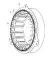
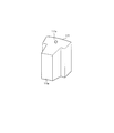
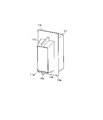
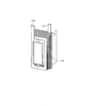
- FIG. 1st embodiment It is a perspective view of a stator of a 1st embodiment. It is a perspective view of the split type stator core of 1st Embodiment. It is a perspective view of the state which insert-molded the insulator to the stator core of 1st Embodiment. It is a perspective view of the state which inserted the coil in the stator core of 1st Embodiment. It is a perspective view in the state where the resin mold part was formed in the stator core of a 1st embodiment. It is a schematic diagram at the time of insert-molding the insulator of the first embodiment. It is a schematic side view of the stator core of 1st Embodiment.
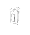
- FIG. 1 the perspective view of the stator of 1st Embodiment is shown.
- FIG. 2 is a perspective view of a split-type stator core.
- FIG. 3 is a perspective view of a state where an insulator is insert-molded into the stator core.
- FIG. 4 is a perspective view of a state where a coil is inserted into the stator core.
- FIG. 5 is a perspective view of a state where the resin mold portion 113 is formed on the stator core. It should be noted that details are different from FIG. 1 for convenience of explanation.
- the stator 10 uses a split-type stator core 111, and is formed by arranging 18 stator core units 110 in an annular shape and fitting an outer ring 102 on the outer periphery.
- a bus bar holder 101 is provided at the coil end of the stator 10.
- the stator core 111 is formed by laminating a plurality of electromagnetic steel plates 150 formed in a substantially T shape by press working.
- the state of lamination is as shown in FIG.
- the stator core 111 is provided with a teeth portion 111a so as to protrude toward the inner peripheral side of the stator 10, and the coil 112 is inserted into the teeth portion 111a after an insulator 114 is provided.
- the insulator 114 is insert-molded with respect to the stator core 111 as shown in FIG.
- the insulator 114 includes a flange portion 114a, an annular portion 114b, and a coil support wall 114c, and is formed of an insulating resin.
- FIG. 6 is a schematic view when insert-molding the insulator.
- the stator core 111 is disposed between the movable mold D1 and the fixed mold D2, so that a cavity B is formed between the movable mold D1 and the stator core 111.
- the insulator 114 is insert-molded by pouring molten resin into the cavity B, cooling, and releasing the mold.
- the cavity B is also provided with a gate for supplying resin.
- the resin poured into the cavity B has a high insulating property and a filler is mixed to ensure heat dissipation.
- the coil 112 is wound by edgewise bending a rectangular conductor having a rectangular cross section.
- a flat conductor is a conductor having a high conductivity such as copper and is covered with an insulating resin such as enamel.
- an outer terminal portion 112a and an inner terminal portion 112b are formed and connected to a bus bar (not shown).
- the coil 112 is inserted into an insulator 114 that is insert-molded in a tooth portion 111 a formed in the stator core 111.
- the resin mold portion 113 is formed so as to cover the coil 112 as shown in FIG.
- the stator 10 according to the first embodiment has the above-described configuration, the following effects can be obtained.
- produces in the stator core 111 when insert-molding the insulator 114 to the stator core 111 is mentioned.
- the stator 10 according to the first embodiment includes a coil 112 formed by winding a rectangular conductor, a stator core 111 including a laminated electromagnetic steel sheet 150 including a tooth portion 111a into which the coil 112 is inserted, and a stator core 111.
- the electromagnetic steel plate 150 constituting the stator core 111 is provided with a crimping recess 111b, and the crimping recess 111b
- the stator core 111 is formed by connecting the electromagnetic steel plates 150 to each other, and the gap d is provided between the first electromagnetic steel plate 150 and the second electromagnetic steel plate 150 to be laminated.
- the resin layer 120 is embedded.
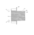
- FIG. 7 shows a schematic side sectional view of the stator core.
- Stator core 111 is formed by laminating electromagnetic steel plates 150.
- the electromagnetic steel sheet 150 is punched with a press, and at the same time, a caulking recess 111b as shown in FIG. 2 is formed.
- the stator core 111 is overlapped with the crimped recess 111b and integrated as shown in FIG.
- FIG. 2 only one crimping recess 111 b is shown, but a plurality of crimping recesses 111 b may be provided depending on the size and required strength of the stator core 111.
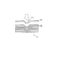
- FIG. 8 shows a schematic cross-sectional view of the stator core impregnated with resin. Therefore, the stator core 111 is caulked by the caulking recess 111b, and then the formed gap d is impregnated with resin. By doing so, the resin layer 120 can be formed between the electromagnetic steel plates 150 as shown in FIG. In forming the resin layer 120, the stator core 111 is held in a jig so as to have a predetermined size, and the molten resin is dropped and impregnated from the side surface of the stator core 111 in this state. . Alternatively, the stator core 111 is formed by a method of immersing and impregnating the stator core 111 in a bath containing molten resin.
- the stator core 111 is preferably placed in a low pressure environment.
- the purpose is to facilitate impregnation of the resin with the gap d.
- the resin for forming the resin layer 120 is an epoxy resin, but other materials can be used as long as insulation can be ensured. A resin having high thermal conductivity is more preferable.
- FIG. 9 is a schematic cross-sectional view showing a state where an insulator is formed on the stator core.
- the resin layer 120 is formed between the electromagnetic steel plates 150 of the stator core 111, and the stator core 111 is extracted from the above-described jig in a state where the resin layer is cured.
- the insulator 114 is insert-molded into a shape as shown in FIG.
- a force is generated in a direction in which the annular portion 114b contracts, and therefore a contraction force F1 shown in FIG. 9 is generated for the caulking recess 111b.
- the electromagnetic steel plates 150 and the resin layers 120 are alternately formed without a gap, the caulking recess 111b is less likely to be distorted, and the deformation of the stator core unit 110 can be suppressed.
- the distortion of the stator core unit 110 is less likely to occur, it becomes easy to ensure the roundness of the inner periphery of the stator 10, and the clearance between the rotor disposed on the inner periphery side (not shown) and the stator 10 is minimized. Can be set to the limit. Since the gap between the stator 10 and the rotor affects the output and performance of the motor using the stator 10, it is desirable that the gap can be narrowed.
- the stator 10 of the second embodiment is substantially the same in configuration as the stator 10 of the first embodiment, but does not form the resin layer 120 between the electromagnetic steel plates 150 but diffuses the fine particles 125.
- FIG. 10 the fragmentary sectional view of the stator core of 2nd Embodiment is shown. This corresponds to FIG. 8 of the first embodiment.
- the stator core 111 is formed by stacking the electromagnetic steel plates 150 and is in the state shown in FIG. In other words, the crimping recess 111 b is crimped and joined, and a gap d is formed between the electromagnetic steel sheets 150.
- the stator core 111 formed by superimposing the electromagnetic steel plates 150 is immersed in the liquid in which the fine particles 125 are diffused. At this time, it is desirable to use a liquid in which the fine particles 125 diffuse evenly. By immersing the stator core 111 in the liquid in which the fine particles 125 are diffused, the fine particles 125 enter the gap d. If the size of the fine particles 125 is optimized, a bridge can be formed in the gap d, and the space between the electromagnetic steel plate 150 and the electromagnetic steel plate 150 can be filled.
- the stator core 111 When the fine particles 125 are sufficiently diffused into the gap d, the stator core 111 is taken out of the liquid and dried to remove the liquid. By doing so, only the fine particles 125 remain in the gap d. It is preferable to use fine particles 125 having the same size and hardness as much as possible, and preferably have insulating properties.
- the stator core 111 is formed using alumina. Thereafter, as in the first embodiment, the insulator 114 is insert-molded as shown in FIGS.
- stator 10 of 2nd Embodiment is comprised in the said procedure, the effect equivalent to 1st Embodiment is acquired.
- shrinkage force F1 generated when the insulator 114 is insert-molded into the stator core 111 and cured is generated, a force causing the fine particles 125 to be crushed is generated, and as a result, the stator core 111 is deformed. It becomes possible to prevent.
- the third embodiment of the present invention is substantially the same as the configuration of the first embodiment, but differs in that the resin layer 120 is not provided.
- the contents will be described below.
- the stator core 111 of the stator 10 of the third embodiment is formed by laminating electromagnetic steel plates 150, and is in the state shown in FIG.
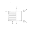
- FIG. 11 shows a side cross-sectional view when forming the insulator according to the third embodiment.
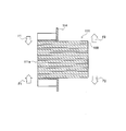
- FIG. 12 is a schematic side view showing the contraction force generated when the insulator is cooled.
- the stator core 111 is formed in the movable mold D1, the fixed mold D2, the second movable mold D3a, and the third movable mold D3b in the state shown in FIG. 11 after being stacked in the state shown in FIG. Arranged in the cavity.
- the fixed mold D ⁇ b> 2 includes a tapered surface D ⁇ b> 21 so as to be convex with respect to the stator core 111, and pressurizes the stator core 111. Further, the inner surface of the movable die D1 is also recessed at the end surface of the tooth portion 111a, that is, the portion where the inner peripheral surface of the stator core 111 abuts, as shown in FIG.
- the insulator 114 is insert-molded, released from the mold, and cooled while applying a force that deforms the stator core 111 in such a state. When the insulator 114 is cooled, the contraction force F1 works as shown in FIG.
- stator core 111 is formed with the tapered surface D21 of the fixed mold D2, and the insulator 114 is insert-molded while the stator core 111 is deformed, the deformation due to the contraction force F1 generated when the insulator 114 is cooled. Balance with. That is, the insulator 114 is insert-molded in a state of being deformed by the taper surface D21 or the like, and the deformation of the stator core 111 and the contraction force F1 cancel each other by the deformation due to the contraction force F1 after mold release. This makes it possible to form the stator core 111 with less deformation. Thereafter, the coil 112 is inserted, and the resin mold portion 113 is formed.
- the insulator 114 is formed by using the fixed die D2 having the tapered surface D21, the second movable die D3a, and the third movable die D3b, thereby utilizing the distortion generated during the cooling of the insulator 114, whereby the insulator 114 is used. Distortion is suppressed by canceling the contraction force F1 generated when 114 contracts.
- the stator 10 using such a stator core unit 110 can minimize a gap with a rotor (not shown).
- the invention has been described according to the present embodiment, the invention is not limited to the embodiment, and by appropriately changing a part of the configuration without departing from the spirit of the invention. It can also be implemented. For example, it does not prevent the materials exemplified in the first to third embodiments from being changed within the scope of the object of the invention.
- the resin layer 120 formed in the first embodiment has been described as an epoxy-based resin, it may be replaced with another resin as long as insulation can be ensured and predetermined heat resistance and heat dissipation can be ensured.
- the fine particles 125 diffused in the second embodiment are not limited to alumina, and may be other ceramics or resinous fine particles as long as they have insulating properties, heat resistance, heat dissipation, and predetermined rigidity.
Landscapes
- Engineering & Computer Science (AREA)
- Power Engineering (AREA)
- Manufacturing & Machinery (AREA)
- Iron Core Of Rotating Electric Machines (AREA)
- Insulation, Fastening Of Motor, Generator Windings (AREA)
Abstract
インシュレータ成形時に発生する応力に対し歪みが発生しにくい固定子又は固定子製造方法を提供するにあたり、導体を巻回して形成したコイルと、コイルを挿入するティースを備え積層された電磁鋼板からなる固定子コアと、固定子コアに挿入したコイルのコイルエンド部分を樹脂で覆った樹脂モールド部と、を備える固定子において、固定子コアを構成する電磁鋼板にはカシメ凹部が設けられ、カシメ凹部を用いて電磁鋼板同士を連結することで固定子コアが形成され、電磁鋼板のうち、積層される第1の電磁鋼板と、第2の電磁鋼板との間に、その隙間を埋める樹脂層を備える。
Description
本発明は、電磁鋼板を積層して固定子コアを形成し固定子に用いる固定子及び固定子の製造方法に関するものであり、固定子コアに生じる歪みを抑制する技術に関する。
近年、自動車の駆動力にモータを用いる需要が増加している。特にハイブリッド車へモータを搭載するにあたっては、小型化、高性能化に加えてコストダウンが重要であり、様々な開発がなされている。
特許文献1にはモータの固定子についての技術が開示されている。
固定子コアのヨーク部の内周側に軸方向に伸びる溝部を形成している。そして、各溝部に充填される樹脂充填部が一体的に設けられる。被覆部材としては樹脂充填部においてステータコアと強固に固定された状態となるため、被覆部材にクラックや剥がれが発生することを抑えることが可能である。
特許文献1にはモータの固定子についての技術が開示されている。
固定子コアのヨーク部の内周側に軸方向に伸びる溝部を形成している。そして、各溝部に充填される樹脂充填部が一体的に設けられる。被覆部材としては樹脂充填部においてステータコアと強固に固定された状態となるため、被覆部材にクラックや剥がれが発生することを抑えることが可能である。
特許文献2には固定子ピース及びモータの固定子に関する技術が開示されている。
電磁鋼板を積層して形成される固定子コアのコアピースは、積み厚方向両端部に位置する一枚の電磁鋼板のティース幅が、積み厚方向中央部に位置する電磁鋼板のティース幅より狭く形成されている。
固定子コア端面に配置される電磁鋼板のティース幅を狭くすることで、インシュレータの筒部の四隅に発生する集中応力を低減させることが可能となる。
電磁鋼板を積層して形成される固定子コアのコアピースは、積み厚方向両端部に位置する一枚の電磁鋼板のティース幅が、積み厚方向中央部に位置する電磁鋼板のティース幅より狭く形成されている。
固定子コア端面に配置される電磁鋼板のティース幅を狭くすることで、インシュレータの筒部の四隅に発生する集中応力を低減させることが可能となる。
特許文献3には、固定子とその製造方法及びこの固定子を用いた電動機についての技術が開示されている。
電磁鋼板を積層して形成される固定子コアのコアピースは、ティース幅が狭い電磁鋼板とティース幅の広い電磁鋼板とからなり、交互に積み重ねられている。
このように固定子コアを形成することで、インサート成形されるインシュレータとの密着性を高めることが可能であり、耐久性を向上させることが可能である。
電磁鋼板を積層して形成される固定子コアのコアピースは、ティース幅が狭い電磁鋼板とティース幅の広い電磁鋼板とからなり、交互に積み重ねられている。
このように固定子コアを形成することで、インサート成形されるインシュレータとの密着性を高めることが可能であり、耐久性を向上させることが可能である。
特許文献4には、分割固定子及び分割固定子製造方法に関する技術が開示されている。
分割型の固定子コアにインシュレータをインサート成形する際に、固定子コアのティース部分の周囲に接着剤層を設けることで、インシュレータに用いる樹脂に混入するフィラーに方向性を持たせないようにする。
インシュレータに混入するフィラーの方向がランダムに配置できることで、熱伝達を阻害するフィラーによる影響を抑えることができ、熱伝導率を向上させることができる。
分割型の固定子コアにインシュレータをインサート成形する際に、固定子コアのティース部分の周囲に接着剤層を設けることで、インシュレータに用いる樹脂に混入するフィラーに方向性を持たせないようにする。
インシュレータに混入するフィラーの方向がランダムに配置できることで、熱伝達を阻害するフィラーによる影響を抑えることができ、熱伝導率を向上させることができる。
しかしながら、特許文献1乃至特許文献4に開示される技術は以下に説明する課題があると考えられる。
コストダウンを推し進めるため、固定子コアに用いる電磁鋼板は、溶接によって接合するのではなく、電磁鋼板にカシメ穴を設け、電磁鋼板の外形をプレス加工で打ち抜いた後に重ねることで、連結する方法が検討されている。
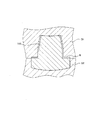
図13に、固定子コアをカシメ接合によって連結する連結部分の模式断面図を示す。
図示されるように電磁鋼板150はカシメ凹部111bを備えており、電磁鋼板150が重ね合わされることで分割型の固定子コア111を形成する。このような電磁鋼板の積層方法を採用することで、電磁鋼板同士を連結するための溶接工程を省くことが可能となり、コストダウンに貢献する。
コストダウンを推し進めるため、固定子コアに用いる電磁鋼板は、溶接によって接合するのではなく、電磁鋼板にカシメ穴を設け、電磁鋼板の外形をプレス加工で打ち抜いた後に重ねることで、連結する方法が検討されている。
図13に、固定子コアをカシメ接合によって連結する連結部分の模式断面図を示す。
図示されるように電磁鋼板150はカシメ凹部111bを備えており、電磁鋼板150が重ね合わされることで分割型の固定子コア111を形成する。このような電磁鋼板の積層方法を採用することで、電磁鋼板同士を連結するための溶接工程を省くことが可能となり、コストダウンに貢献する。
ただし、図13に示すようにカシメ凹部111bが重ねられることで、隙間dが生じる結果となる。この隙間dは電磁鋼板の厚みに左右され、カシメ結合をする限り、ゼロにすることは困難である。
図14に、固定子コアにインシュレータをインサート成形した状態の断面図を示す。
インシュレータ114をインサート成形すると、図14に示すようにティース部111aをインシュレータ114が覆うことになる。しかし、樹脂で形成されるインシュレータ114と、金属製の電磁鋼板150を積層して形成される分割型の固定子コア111の熱膨張率は異なる。このため、インシュレータ114を成型し冷却するにあたって、ティース部111a側に収縮力F1が、分割型の固定子コア111の外周側に拡張力F2が発生する。
図14に、固定子コアにインシュレータをインサート成形した状態の断面図を示す。
インシュレータ114をインサート成形すると、図14に示すようにティース部111aをインシュレータ114が覆うことになる。しかし、樹脂で形成されるインシュレータ114と、金属製の電磁鋼板150を積層して形成される分割型の固定子コア111の熱膨張率は異なる。このため、インシュレータ114を成型し冷却するにあたって、ティース部111a側に収縮力F1が、分割型の固定子コア111の外周側に拡張力F2が発生する。
これは、図13に示すように積層された電磁鋼板150同士の間に、隙間dが形成されてしまうためである。電磁鋼板150に形成されるカシメ凹部111bを重ねて結合することで、隙間dが形成されてしまう点は避けられない。そのため、熱膨張率の差によってインシュレータ114にティース部111aが締め付けられることで、分割型の固定子コア111が変形する虞がある。
分割型の固定子コア111の内周側は図示しない回転子とのクリアランスが保たれる必要があり、分割型の固定子コア111の変形は回転子との干渉を引き起こす虞もある。また、固定子コア111に歪があると、モータ駆動時の振動や音などの発生を招き、寿命が短くなるなどの問題もある。
特許文献1乃至特許文献4には、このような事態を想定した技術ではないと考えられ、カシメ凹部111bを備えた分割型の固定子コア111を用いた場合には、上述した問題が発生する虞がある。
分割型の固定子コア111の内周側は図示しない回転子とのクリアランスが保たれる必要があり、分割型の固定子コア111の変形は回転子との干渉を引き起こす虞もある。また、固定子コア111に歪があると、モータ駆動時の振動や音などの発生を招き、寿命が短くなるなどの問題もある。
特許文献1乃至特許文献4には、このような事態を想定した技術ではないと考えられ、カシメ凹部111bを備えた分割型の固定子コア111を用いた場合には、上述した問題が発生する虞がある。
そこで、本発明はこのような課題を解決するために、インシュレータ成形時に発生する応力に対し歪みが発生しにくい固定子又は固定子製造方法を提供することを目的とする。
前記目的を達成するために、本発明の一態様による固定子は、以下のような特徴を有する。
(1)導体を巻回して形成したコイルと、前記コイルを挿入するティースを備え積層された電磁鋼板からなる固定子コアと、前記固定子コアに挿入した前記コイルのコイルエンド部分を樹脂で覆った樹脂モールド部と、を備える固定子において、前記固定子コアを構成する前記電磁鋼板にはカシメ凹部が設けられ、前記カシメ凹部を用いて前記電磁鋼板同士を連結することで前記固定子コアが形成され、前記電磁鋼板のうち、積層される第1の電磁鋼板と、第2の電磁鋼板との間に、その隙間を埋める変形防止層を備えることを特徴とする。
(1)導体を巻回して形成したコイルと、前記コイルを挿入するティースを備え積層された電磁鋼板からなる固定子コアと、前記固定子コアに挿入した前記コイルのコイルエンド部分を樹脂で覆った樹脂モールド部と、を備える固定子において、前記固定子コアを構成する前記電磁鋼板にはカシメ凹部が設けられ、前記カシメ凹部を用いて前記電磁鋼板同士を連結することで前記固定子コアが形成され、前記電磁鋼板のうち、積層される第1の電磁鋼板と、第2の電磁鋼板との間に、その隙間を埋める変形防止層を備えることを特徴とする。
(2)(1)に記載の固定子において、前記変形防止層が、前記隙間に充填され凝固した樹脂よりなることを特徴とする。
(3)(1)に記載の固定子において、前記変形防止層が、前記隙間に分散された微粒子よりなることを特徴とする。
また、前記目的を達成するために、本発明の一態様による固定子製造方法は以下のような特徴を有する。
(4)導体を巻回してコイルを形成し、前記コイルを積層された電磁鋼板からなる固定子コアに形成されたティースに挿入し、前記固定子コアの前記コイルエンド部分を樹脂で覆う樹脂モールド部を形成する、固定子製造方法において、前記電磁鋼板に用いられたカシメ凹部を用いて前記電磁鋼板を積層して、前記固定子コアを形成し、前記積層される第1の電磁鋼板と、第2の電磁鋼板との間に、樹脂を含浸させて硬化させ、前記固定子コアを金型にセットし、インシュレータをインサート成形により形成することを特徴とする。
(4)導体を巻回してコイルを形成し、前記コイルを積層された電磁鋼板からなる固定子コアに形成されたティースに挿入し、前記固定子コアの前記コイルエンド部分を樹脂で覆う樹脂モールド部を形成する、固定子製造方法において、前記電磁鋼板に用いられたカシメ凹部を用いて前記電磁鋼板を積層して、前記固定子コアを形成し、前記積層される第1の電磁鋼板と、第2の電磁鋼板との間に、樹脂を含浸させて硬化させ、前記固定子コアを金型にセットし、インシュレータをインサート成形により形成することを特徴とする。
(5)導体を巻回してコイルを形成し、前記コイルを積層された電磁鋼板からなる固定子コアに形成されたティースに挿入し、前記固定子コアの前記コイルエンド部分を樹脂で覆う樹脂モールド部を形成する、固定子製造方法において、前記電磁鋼板に用いられたカシメ凹部を用いて前記電磁鋼板を積層して、前記固定子コアを形成し、前記積層される第1の電磁鋼板と、第2の電磁鋼板との間に、微粒子を分散させた液体を含浸させ、前記固定子コアを乾燥させ、前記固定子コアを金型にセットし、インシュレータをインサート成形により形成することを特徴とする。
(6)導体を巻回してコイルを形成し、前記コイルを積層された電磁鋼板からなる固定子コアに形成されたティースに挿入し、前記固定子コアの前記コイルエンド部分を樹脂で覆う樹脂モールド部を形成する、固定子製造方法において、前記固定子コアを、曲面を有する金型に挿入することで、前記ティース部の中央部が弓なりに凸になるように保持し、前記固定子コアにインシュレータをインサート成形することを特徴とする。
このような特徴を有する本発明の一態様による固定子により、以下のような作用、効果が得られる。
上記(1)に記載される発明の態様は、導体を巻回して形成したコイルと、コイルを挿入するティースを備え積層された電磁鋼板からなる固定子コアと、固定子コアに挿入したコイルのコイルエンド部分を樹脂で覆った樹脂モールド部と、を備える固定子において、固定子コアを構成する電磁鋼板にはカシメ凹部が設けられ、カシメ凹部を用いて電磁鋼板同士を連結することで固定子コアが形成され、電磁鋼板のうち、積層される第1の電磁鋼板と、第2の電磁鋼板との間に、その隙間を埋める変形防止層を備えるものである。
上記(1)に記載される発明の態様は、導体を巻回して形成したコイルと、コイルを挿入するティースを備え積層された電磁鋼板からなる固定子コアと、固定子コアに挿入したコイルのコイルエンド部分を樹脂で覆った樹脂モールド部と、を備える固定子において、固定子コアを構成する電磁鋼板にはカシメ凹部が設けられ、カシメ凹部を用いて電磁鋼板同士を連結することで固定子コアが形成され、電磁鋼板のうち、積層される第1の電磁鋼板と、第2の電磁鋼板との間に、その隙間を埋める変形防止層を備えるものである。
固定子コアは、カシメ凹部によって連結されることで電磁鋼板同士の間にわずかな隙間を生じるが、その隙間を埋めるようにして変形防止層を備えている。このため、この固定子コアにインシュレータをインサート成形し、インシュレータを構成する樹脂の収縮が発生しても、固定子コアが変形するようなことが無くなる。
これは、単純に電磁鋼板同士の間の隙間が変形防止層によって埋められることによるものであり、固定子コアと回転子との干渉を防ぐことが可能となる。
これは、単純に電磁鋼板同士の間の隙間が変形防止層によって埋められることによるものであり、固定子コアと回転子との干渉を防ぐことが可能となる。
上記(2)に記載の発明の態様は、(1)に記載の固定子において、変形防止層が、隙間に充填され凝固した樹脂よりなるものである。
変形防止層が、隙間に樹脂層を形成してなるので、インシュレータを構成する樹脂の収縮が発生しても、樹脂層が変形防止層として機能し、固定子コアが変形するようなことが無くなる。
その結果、固定子コアと固定子コア内部に配置される回転子との干渉を防ぐことが可能となる。
変形防止層が、隙間に樹脂層を形成してなるので、インシュレータを構成する樹脂の収縮が発生しても、樹脂層が変形防止層として機能し、固定子コアが変形するようなことが無くなる。
その結果、固定子コアと固定子コア内部に配置される回転子との干渉を防ぐことが可能となる。
上記(3)に記載の発明の態様は、(1)に記載の固定子において、隙間に分散された微粒子よりなるものである。
変形防止層が、隙間に微粒子を分散させることよりなるので、インシュレータを構成する樹脂の収縮が発生しても、微粒子が変形防止層として機能し、固定子コアが変形するようなことが無くなる。
その結果、固定子コアと固定子コア内部に配置される回転子との干渉を防ぐことが可能となる。
変形防止層が、隙間に微粒子を分散させることよりなるので、インシュレータを構成する樹脂の収縮が発生しても、微粒子が変形防止層として機能し、固定子コアが変形するようなことが無くなる。
その結果、固定子コアと固定子コア内部に配置される回転子との干渉を防ぐことが可能となる。
また、このような特徴を有する本発明の一態様による固定子製造方法により、以下のような作用、効果が得られる。
上記(4)に記載の発明の態様は、導体を巻回してコイルを形成し、コイルを積層された電磁鋼板からなる固定子コアに形成されたティースに挿入し、固定子コアのコイルエンド部分を樹脂で覆う樹脂モールド部を形成する、固定子製造方法において、電磁鋼板に用いられたカシメ凹部を用いて電磁鋼板を積層して、固定子コアを形成し、積層される第1の電磁鋼板と、第2の電磁鋼板との間に、樹脂を含浸させて硬化させ、固定子コアを金型にセットし、インシュレータをインサート成形により形成するものである。
上記(4)に記載の発明の態様は、導体を巻回してコイルを形成し、コイルを積層された電磁鋼板からなる固定子コアに形成されたティースに挿入し、固定子コアのコイルエンド部分を樹脂で覆う樹脂モールド部を形成する、固定子製造方法において、電磁鋼板に用いられたカシメ凹部を用いて電磁鋼板を積層して、固定子コアを形成し、積層される第1の電磁鋼板と、第2の電磁鋼板との間に、樹脂を含浸させて硬化させ、固定子コアを金型にセットし、インシュレータをインサート成形により形成するものである。
固定子コアを構成する積層された電磁鋼板の間に樹脂層を形成することで、固定子コアにインシュレータがインサート成形された際に発生する収縮力による変形を抑制することが可能となる。
固定子コアを構成する電磁鋼板とインシュレータとの収縮率は異なる。これは、電磁鋼板が金属で構成されるのに対してインシュレータが樹脂で形成されており、熱収縮率が異なる結果、インシュレータのインサート成形時に加熱、冷却されることで固定子コアに応力が発生する。
固定子コアを構成する電磁鋼板とインシュレータとの収縮率は異なる。これは、電磁鋼板が金属で構成されるのに対してインシュレータが樹脂で形成されており、熱収縮率が異なる結果、インシュレータのインサート成形時に加熱、冷却されることで固定子コアに応力が発生する。
インシュレータは、固定子コアのティース部分を覆う構造であり、収縮によってティース部分のみを締め付ける。その結果、カシメ接合された電磁鋼板を固定子コアに用いる場合は、課題に示す通りに固定子コアの内周側が締め付けられ外周側が広がる形状に歪みが発生する。固定子コアが歪むと回転子とのクリアランスを大きく取らなければならず、好ましくない。このために、電磁鋼板の間に固定子の変形を防止することを目的とした樹脂層を形成し、その後にインシュレータを形成することで、前述した歪みの発生を防ぐことを可能としている。
上記(5)に記載の発明の態様は、導体を巻回してコイルを形成し、コイルを積層された電磁鋼板からなる固定子コアに形成されたティースに挿入し、固定子コアのコイルエンド部分を樹脂で覆う樹脂モールド部を形成する、固定子製造方法において、電磁鋼板に用いられたカシメ凹部を用いて電磁鋼板を積層して、固定子コアを形成し、積層される第1の電磁鋼板と、第2の電磁鋼板との間に、微粒子を分散させた液体を含浸させ、固定子コアを乾燥させ、固定子コアを金型にセットし、インシュレータをインサート成形により形成するものである。
上記(4)に記載の固定子製造方法において形成した樹脂層の代わりに、微粒子を分散させている。すなわち、電磁鋼板と電磁鋼板との間に、微粒子を分散させて固定子コアを形成している。その結果、インサート成形時の圧縮応力による歪みを低減することが可能となる。
固定子コアの変形を抑制することで、固定子と回転子とのクリアランスを最小限に設定することが可能となる。
固定子コアの変形を抑制することで、固定子と回転子とのクリアランスを最小限に設定することが可能となる。
上記(6)に記載の発明の態様は、導体を巻回してコイルを形成し、コイルを積層された電磁鋼板からなる固定子コアに形成されたティースに挿入し、固定子コアのコイルエンド部分を樹脂で覆う樹脂モールド部を形成する、固定子製造方法において、固定子コアを、曲面を有する金型に挿入することで、前記ティース部の中央部が弓なりに凸になるように保持し、前記固定子コアにインシュレータをインサート成形するものである。
固定子コアを積層し、インシュレータをインサート成形する際に、金型に曲面を設けて固定子コアに応力をかけた状態でインシュレータを形成することで、形成後、冷却時に収縮力が発生する際に固定子コアに生じていた歪みとは逆方向に歪みが発生する。
すなわち、事前に金型によって固定子コアに応力をかけておくことで、後に発生する応力と相殺させることが可能となる。
すなわち、事前に金型によって固定子コアに応力をかけておくことで、後に発生する応力と相殺させることが可能となる。
インシュレータを形成する際に発生する応力のうちに問題になるのは、固定子コア内周側において、固定子軸方向に潰れようとする力であり、図14で示す収縮力F1である。したがって、収縮力F1と逆方向、すなわち固定子コアの中央部を外周側から押し、固定子コアの内周側が開く方向に応力をかけておくことでこれに対応する。
その結果、歪みの少ない固定子を形成することが可能となる。
その結果、歪みの少ない固定子を形成することが可能となる。
まず、本発明の第1の実施形態について説明をする。
(第1実施形態)
図1に、第1実施形態の固定子の斜視図を示す。なお、説明の都合上、固定子コアの細部は省略している。
図2に、分割型の固定子コアの斜視図を示す。図3は、固定子コアにインシュレータをインサート成形した状態の斜視図である。図4は、固定子コアにコイルを挿入した状態の斜視図である。図5は、固定子コアに樹脂モールド部113を形成した状態の斜視図である。なお、図1とは説明の都合上細部が異なる。
固定子10は、分割型の固定子コア111を用いており、固定子コアユニット110を円環状に18個配置し、外周にアウターリング102を嵌めることで形成されている。固定子10のコイルエンドにはバスバホルダ101が備えられている。
(第1実施形態)
図1に、第1実施形態の固定子の斜視図を示す。なお、説明の都合上、固定子コアの細部は省略している。
図2に、分割型の固定子コアの斜視図を示す。図3は、固定子コアにインシュレータをインサート成形した状態の斜視図である。図4は、固定子コアにコイルを挿入した状態の斜視図である。図5は、固定子コアに樹脂モールド部113を形成した状態の斜視図である。なお、図1とは説明の都合上細部が異なる。
固定子10は、分割型の固定子コア111を用いており、固定子コアユニット110を円環状に18個配置し、外周にアウターリング102を嵌めることで形成されている。固定子10のコイルエンドにはバスバホルダ101が備えられている。
固定子コア111は、図2に示すようにプレス加工により略T字状に形成された電磁鋼板150を複数枚積層して形成されている。積層の状況は図13に示した通りである。
固定子コア111は固定子10の内周側に突出するようにティース部111aを備えており、ティース部111aにはインシュレータ114を備えた上でコイル112が挿入される。
インシュレータ114は、固定子コア111に対して図3に示されるようにインサート成形される。インシュレータ114は、鍔部114a、環状部114b、コイル支持壁114cを備えており、絶縁性を有する樹脂で形成されている。
固定子コア111は固定子10の内周側に突出するようにティース部111aを備えており、ティース部111aにはインシュレータ114を備えた上でコイル112が挿入される。
インシュレータ114は、固定子コア111に対して図3に示されるようにインサート成形される。インシュレータ114は、鍔部114a、環状部114b、コイル支持壁114cを備えており、絶縁性を有する樹脂で形成されている。
図6は、インシュレータをインサート成形する際の模式図である。
固定子コア111は、可動型D1と固定型D2との間に配設されることで、可動型D1と固定子コア111との間にキャビティBが形成される。このキャビティBに溶融した樹脂を流し込み、冷却、離型することで、インシュレータ114をインサート成形する。なお、図では省略しているが、キャビティBには樹脂を供給するための湯口なども設けられている。また、キャビティBに流し込む樹脂は絶縁性が高く、放熱性も確保するためにフィラーが混入されている。
固定子コア111は、可動型D1と固定型D2との間に配設されることで、可動型D1と固定子コア111との間にキャビティBが形成される。このキャビティBに溶融した樹脂を流し込み、冷却、離型することで、インシュレータ114をインサート成形する。なお、図では省略しているが、キャビティBには樹脂を供給するための湯口なども設けられている。また、キャビティBに流し込む樹脂は絶縁性が高く、放熱性も確保するためにフィラーが混入されている。
コイル112は矩形断面を有する平角導体をエッジワイズ曲げ加工して巻回されている。平角導体は銅などの導電性の高い導体の周囲にエナメルなどの絶縁性の高い樹脂にて絶縁被覆したものである。コイル112のコイルエンドの片側には、外側端子部112aと内側端子部112bが形成されており、図示しないバスバと接続される。コイル112は、図4に示すように固定子コア111に形成されるティース部111aにインサート成形されたインシュレータ114に挿入される。
固定子コア111にコイル112が挿入された後、図5に示されるようにコイル112を覆うように樹脂モールド部113が形成される。
固定子コア111にコイル112が挿入された後、図5に示されるようにコイル112を覆うように樹脂モールド部113が形成される。
第1実施形態の固定子10は上記構成であるので、以下に説明する作用効果を奏する。
まず、固定子コア111にインシュレータ114をインサート成形する際に、固定子コア111に発生する歪みを抑制することが可能である点が挙げられる。
第1実施形態の固定子10は、平角導体を巻回して形成したコイル112と、コイル112を挿入するティース部111aを備え積層された電磁鋼板150からなる固定子コア111と、固定子コア111に挿入したコイル112のコイルエンド部分を樹脂で覆った樹脂モールド部113と、を備える固定子10において、固定子コア111を構成する電磁鋼板150にはカシメ凹部111bが設けられ、カシメ凹部111bを用いて電磁鋼板150同士を連結することで固定子コア111が形成され、電磁鋼板150のうち、積層される第1の電磁鋼板150と、第2の電磁鋼板150との間に、その隙間dを埋める樹脂層120を備えるものである。
まず、固定子コア111にインシュレータ114をインサート成形する際に、固定子コア111に発生する歪みを抑制することが可能である点が挙げられる。
第1実施形態の固定子10は、平角導体を巻回して形成したコイル112と、コイル112を挿入するティース部111aを備え積層された電磁鋼板150からなる固定子コア111と、固定子コア111に挿入したコイル112のコイルエンド部分を樹脂で覆った樹脂モールド部113と、を備える固定子10において、固定子コア111を構成する電磁鋼板150にはカシメ凹部111bが設けられ、カシメ凹部111bを用いて電磁鋼板150同士を連結することで固定子コア111が形成され、電磁鋼板150のうち、積層される第1の電磁鋼板150と、第2の電磁鋼板150との間に、その隙間dを埋める樹脂層120を備えるものである。
図7に、固定子コアの概略側面断面図を示す。
固定子コア111は、電磁鋼板150が積層されて形成される。電磁鋼板150は、プレスで打ち抜かれると同時に、図2で示されるようなカシメ凹部111bが形成される。そして、プレス加工後、加圧しながら加工済みの電磁鋼板150と重ねられ、固定子コア111は図13に示されるようにカシメ凹部111bで結合され、一体化される。なお、図2にはカシメ凹部111bは1カ所しか示されていないが、固定子コア111の大きさや必要強度によってはカシメ凹部111bを複数設けられても良い。
このように固定子コア111をカシメ加工によって結合すると、図7及び図13に示すように電磁鋼板150同士の間に僅かな隙間dが発生してしまう。これは、課題にも示した通りカシメ凹部111bを用いて電磁鋼板150同士を結合している為であり、電磁鋼板150の板厚の関係でどうしても隙間dの発生は避けられない。
固定子コア111は、電磁鋼板150が積層されて形成される。電磁鋼板150は、プレスで打ち抜かれると同時に、図2で示されるようなカシメ凹部111bが形成される。そして、プレス加工後、加圧しながら加工済みの電磁鋼板150と重ねられ、固定子コア111は図13に示されるようにカシメ凹部111bで結合され、一体化される。なお、図2にはカシメ凹部111bは1カ所しか示されていないが、固定子コア111の大きさや必要強度によってはカシメ凹部111bを複数設けられても良い。
このように固定子コア111をカシメ加工によって結合すると、図7及び図13に示すように電磁鋼板150同士の間に僅かな隙間dが発生してしまう。これは、課題にも示した通りカシメ凹部111bを用いて電磁鋼板150同士を結合している為であり、電磁鋼板150の板厚の関係でどうしても隙間dの発生は避けられない。
図8に、固定子コアに樹脂を含浸させた状態の概略断面図を示す。
そこで固定子コア111は、カシメ凹部111bにてカシメ加工された後、形成されている隙間dに樹脂を含浸させる。こうすることで、図8に示すように電磁鋼板150の間に樹脂層120を形成することができる。
この樹脂層120の形成にあたっては、固定子コア111を所定の寸法となるように治具の中に入れて保持し、その状態で固定子コア111の側面から溶融した樹脂を滴下して含浸させる。或いは、固定子コア111を溶融した樹脂の入った槽の中に漬けて含浸させる方法などを用いて形成される。
そこで固定子コア111は、カシメ凹部111bにてカシメ加工された後、形成されている隙間dに樹脂を含浸させる。こうすることで、図8に示すように電磁鋼板150の間に樹脂層120を形成することができる。
この樹脂層120の形成にあたっては、固定子コア111を所定の寸法となるように治具の中に入れて保持し、その状態で固定子コア111の側面から溶融した樹脂を滴下して含浸させる。或いは、固定子コア111を溶融した樹脂の入った槽の中に漬けて含浸させる方法などを用いて形成される。
樹脂を含浸させるためには、固定子コア111は低圧環境におくことが好ましい。樹脂を隙間dに含浸し易くする目的である。
また、固定子コア111の側面に樹脂を滴下する場合でも、樹脂槽に漬ける場合でも、乾燥させる前に固定子コア111の周囲についた余分な樹脂を拭き取る必要がある。
樹脂層120を形成する樹脂はエポキシ系の樹脂を用いているが、絶縁性を確保できれば、他の材質でも代替可能である。熱伝導性が高い樹脂であれば、更に好ましい。
また、固定子コア111の側面に樹脂を滴下する場合でも、樹脂槽に漬ける場合でも、乾燥させる前に固定子コア111の周囲についた余分な樹脂を拭き取る必要がある。
樹脂層120を形成する樹脂はエポキシ系の樹脂を用いているが、絶縁性を確保できれば、他の材質でも代替可能である。熱伝導性が高い樹脂であれば、更に好ましい。
図9に、固定子コアにインシュレータを形成した状態の概略断面図を示す。
こうして、固定子コア111の電磁鋼板150の間に樹脂層120を形成し、樹脂層が硬化した状態で、前述の治具から固定子コア111を抜き出す。その結果、図9に示すような形状にインシュレータ114がインサート成形される。
インシュレータ114をインサート成形によってカシメ凹部111bの周囲を覆うように形成すると、環状部114bが収縮する方向に力が発生するので、図9に示す収縮力F1がカシメ凹部111bに対して生じる。
しかし、電磁鋼板150と樹脂層120が交互に隙間無く形成されているので、カシメ凹部111bには歪みが生じにくくなり、固定子コアユニット110の変形を抑えることが可能となる。
こうして、固定子コア111の電磁鋼板150の間に樹脂層120を形成し、樹脂層が硬化した状態で、前述の治具から固定子コア111を抜き出す。その結果、図9に示すような形状にインシュレータ114がインサート成形される。
インシュレータ114をインサート成形によってカシメ凹部111bの周囲を覆うように形成すると、環状部114bが収縮する方向に力が発生するので、図9に示す収縮力F1がカシメ凹部111bに対して生じる。
しかし、電磁鋼板150と樹脂層120が交互に隙間無く形成されているので、カシメ凹部111bには歪みが生じにくくなり、固定子コアユニット110の変形を抑えることが可能となる。
固定子コアユニット110の歪みが生じにくくなることで、固定子10の内周の真円度を確保しやすくなり、図示しない内周側に配置される回転子と固定子10とのクリアランスを最小限に設定することができる。
固定子10と回転子のギャップは、固定子10を用いるモータの出力や性能に影響するため、このギャップを狭くできることは望ましい。
固定子10と回転子のギャップは、固定子10を用いるモータの出力や性能に影響するため、このギャップを狭くできることは望ましい。
次に、本発明の第2の実施形態について説明する。
(第2実施形態)
第2実施形態の固定子10は第1実施形態の固定子10とその構成においてほぼ同じであるが、電磁鋼板150の間に樹脂層120を形成するのではなく、微粒子125を拡散させる点で異なる。
図10に、第2実施形態の固定子コアの部分断面図を示す。第1実施形態の図8に対応する。
固定子コア111は電磁鋼板150が重ねられて形成されて、図7で示した状態となる。つまりカシメ凹部111bでカシメ加工されて結合された状態であり、電磁鋼板150の間には隙間dが形成されている。
(第2実施形態)
第2実施形態の固定子10は第1実施形態の固定子10とその構成においてほぼ同じであるが、電磁鋼板150の間に樹脂層120を形成するのではなく、微粒子125を拡散させる点で異なる。
図10に、第2実施形態の固定子コアの部分断面図を示す。第1実施形態の図8に対応する。
固定子コア111は電磁鋼板150が重ねられて形成されて、図7で示した状態となる。つまりカシメ凹部111bでカシメ加工されて結合された状態であり、電磁鋼板150の間には隙間dが形成されている。
そして、電磁鋼板150が重ねられて形成された固定子コア111を、微粒子125が拡散された液体の中に浸ける。この時、微粒子125が均等に拡散するような液体を用いることが望ましい。
微粒子125が拡散している状態の液体に固定子コア111を浸けることで、隙間d内に微粒子125が侵入していく。そして、微粒子125の大きさが最適化されていれば、隙間dでブリッジを形成し、電磁鋼板150と電磁鋼板150の間の空間を埋めることが可能となる。
微粒子125が拡散している状態の液体に固定子コア111を浸けることで、隙間d内に微粒子125が侵入していく。そして、微粒子125の大きさが最適化されていれば、隙間dでブリッジを形成し、電磁鋼板150と電磁鋼板150の間の空間を埋めることが可能となる。
十分に隙間dに微粒子125が拡散できたら、液体から固定子コア111を取り出し、乾燥させることで液体を取り除く。こうすることで隙間dには微粒子125のみが残る。用いる微粒子125は可能な限り均等なサイズで硬度があるものを使うことが好ましく、絶縁性を有していることが好ましい。第2実施形態ではアルミナを用いて固定子コア111を形成した。
その後は、第1実施形態と同様にして図6、図9に示すようにインシュレータ114をインサート成形する。
その後は、第1実施形態と同様にして図6、図9に示すようにインシュレータ114をインサート成形する。
第2実施形態の固定子10は上記手順で構成されるので、第1実施形態と同等の効果が得られる。
すなわち、インシュレータ114を固定子コア111にインサート成形して、硬化させる際に発生する収縮力F1に対し、微粒子125に潰れまいとする力が発生するので、結果的に固定子コア111の変形を防止することが可能となる。
すなわち、インシュレータ114を固定子コア111にインサート成形して、硬化させる際に発生する収縮力F1に対し、微粒子125に潰れまいとする力が発生するので、結果的に固定子コア111の変形を防止することが可能となる。
次に、本発明の第3の実施形態について説明する。
(第3実施形態)
本発明の第3実施形態は、第1実施形態の構成とほぼ同じであるが、樹脂層120を設けない点で異なる。以下にその内容について説明を行う。
第3実施形態の固定子10の固定子コア111は、電磁鋼板150を積層することで形成され、図7に示す状態となる。
図11に、第3実施形態のインシュレータ形成時の側面断面図を示す。
図12に、インシュレータを冷却する時に発生する収縮力を側面模式図に示す。
固定子コア111は、図7に示す状態に重ねられた後、図11に示すような状態で可動型D1、固定型D2及び第2可動型D3a、第3可動型D3bの中に形成されるキャビティに配設される。
(第3実施形態)
本発明の第3実施形態は、第1実施形態の構成とほぼ同じであるが、樹脂層120を設けない点で異なる。以下にその内容について説明を行う。
第3実施形態の固定子10の固定子コア111は、電磁鋼板150を積層することで形成され、図7に示す状態となる。
図11に、第3実施形態のインシュレータ形成時の側面断面図を示す。
図12に、インシュレータを冷却する時に発生する収縮力を側面模式図に示す。
固定子コア111は、図7に示す状態に重ねられた後、図11に示すような状態で可動型D1、固定型D2及び第2可動型D3a、第3可動型D3bの中に形成されるキャビティに配設される。
固定型D2は、固定子コア111に対して凸になるようにテーパ面D21を備えており、固定子コア111に対して加圧する。また、可動型D1の内面も、ティース部111aの端面、すなわち固定子コア111の内周面が当接する部分が凹んでおり、図11に示すような状態となっている。
このような状態に固定子コア111が変形するような力を加えながらインシュレータ114をインサート成形し、離型し、冷却する。インシュレータ114を冷却すると、図12に示すように収縮力F1が働くことになる。
このような状態に固定子コア111が変形するような力を加えながらインシュレータ114をインサート成形し、離型し、冷却する。インシュレータ114を冷却すると、図12に示すように収縮力F1が働くことになる。
しかし、固定子コア111は固定型D2のテーパ面D21が形成されており、固定子コア111を変形させながらインシュレータ114をインサート成形しているため、インシュレータ114の冷却時に発生する収縮力F1による変形と釣り合う。すなわち、テーパ面D21等によって変形された状態でインシュレータ114がインサート成形され、離型後に収縮力F1による変形によって、固定子コア111の歪みと収縮力F1が相殺し合う。このことで、変形の少ない固定子コア111の形成が可能となる。
その後、コイル112を挿入し、樹脂モールド部113を形成する。
その後、コイル112を挿入し、樹脂モールド部113を形成する。
このように、テーパ面D21を備えた固定型D2及び第2可動型D3a、第3可動型D3bを用いてインシュレータ114を形成することで、インシュレータ114冷却時に発生する歪みを利用することで、インシュレータ114が収縮するときに発生する収縮力F1を相殺して歪みを抑制する。
このような固定子コアユニット110を用いた固定子10は、図示しない回転子とのギャップを最低限に抑えることが可能となる。
このような固定子コアユニット110を用いた固定子10は、図示しない回転子とのギャップを最低限に抑えることが可能となる。
以上、本実施形態に則して発明を説明したが、この発明は前記実施形態に限定されるものではなく、発明の趣旨を逸脱することのない範囲で構成の一部を適宜変更することにより実施することもできる。
例えば、第1実施形態乃至第3実施形態において例示した材質を、発明の目的の範囲内で変更することを妨げない。例えば、第1実施形態で形成される樹脂層120はエポキシ系の樹脂と説明しているが、絶縁性が確保でき、所定の耐熱性、放熱性が確保できれば他の樹脂と置き換えても良い。また、第2実施形態で拡散される微粒子125についてもアルミナに限られず、絶縁性や耐熱性、放熱性、所定の剛性を有すれば、他のセラミックスでも良いし、樹脂性の微粒子でも良い。
例えば、第1実施形態乃至第3実施形態において例示した材質を、発明の目的の範囲内で変更することを妨げない。例えば、第1実施形態で形成される樹脂層120はエポキシ系の樹脂と説明しているが、絶縁性が確保でき、所定の耐熱性、放熱性が確保できれば他の樹脂と置き換えても良い。また、第2実施形態で拡散される微粒子125についてもアルミナに限られず、絶縁性や耐熱性、放熱性、所定の剛性を有すれば、他のセラミックスでも良いし、樹脂性の微粒子でも良い。
10 固定子
101 バスバホルダ
102 アウターリング
110 固定子コアユニット
111 固定子コア
111a ティース部
111b カシメ凹部
112 コイル
112a 外側端子部
112b 内側端子部
113 樹脂モールド部
114 インシュレータ
114a 鍔部
114b 環状部
114c コイル支持壁
120 樹脂層
125 微粒子
150 電磁鋼板
B キャビティ
D1 可動型
D2 固定型
D21 テーパ面
D3a 第2可動型
D3b 第3可動型
F1 収縮力
F2 拡張力
d 隙間
101 バスバホルダ
102 アウターリング
110 固定子コアユニット
111 固定子コア
111a ティース部
111b カシメ凹部
112 コイル
112a 外側端子部
112b 内側端子部
113 樹脂モールド部
114 インシュレータ
114a 鍔部
114b 環状部
114c コイル支持壁
120 樹脂層
125 微粒子
150 電磁鋼板
B キャビティ
D1 可動型
D2 固定型
D21 テーパ面
D3a 第2可動型
D3b 第3可動型
F1 収縮力
F2 拡張力
d 隙間
Claims (6)
- 導体を巻回して形成したコイルと、前記コイルを挿入するティースを備え積層された電磁鋼板からなる固定子コアと、前記固定子コアに挿入した前記コイルのコイルエンド部分を樹脂で覆った樹脂モールド部と、を備える固定子において、
前記固定子コアを構成する前記電磁鋼板にはカシメ凹部が設けられ、
前記カシメ凹部を用いて前記電磁鋼板同士を連結することで前記固定子コアが形成され、
前記電磁鋼板のうち、積層される第1の電磁鋼板と、第2の電磁鋼板との間に、その隙間を埋める変形防止層を備えることを特徴とする固定子。 - 請求項1に記載の固定子において、
前記変形防止層が、前記隙間に充填され凝固した樹脂よりなることを特徴とする固定子。 - 請求項1に記載の固定子において、
前記変形防止層が、前記隙間に分散された微粒子よりなることを特徴とする固定子。 - 導体を巻回してコイルを形成し、前記コイルを積層された電磁鋼板からなる固定子コアに形成されたティースに挿入し、前記固定子コアの前記コイルエンド部分を樹脂で覆う樹脂モールド部を形成する、固定子製造方法において、
前記電磁鋼板に用いられたカシメ凹部を用いて前記電磁鋼板を積層して、前記固定子コアを形成し、
前記積層される第1の電磁鋼板と、第2の電磁鋼板との間に、樹脂を含浸させて硬化させ、
前記固定子コアを金型にセットし、インシュレータをインサート成形により形成することを特徴とする固定子製造方法。 - 導体を巻回してコイルを形成し、前記コイルを積層された電磁鋼板からなる固定子コアに形成されたティースに挿入し、前記固定子コアの前記コイルエンド部分を樹脂で覆う樹脂モールド部を形成する、固定子製造方法において、
前記電磁鋼板に用いられたカシメ凹部を用いて前記電磁鋼板を積層して、前記固定子コアを形成し、
前記積層される第1の電磁鋼板と、第2の電磁鋼板との間に、微粒子を分散させた液体を含浸させ、
前記固定子コアを乾燥させ、
前記固定子コアを金型にセットし、インシュレータをインサート成形により形成することを特徴とする固定子製造方法。 - 導体を巻回してコイルを形成し、前記コイルを積層された電磁鋼板からなる固定子コアに形成されたティースに挿入し、前記固定子コアの前記コイルエンド部分を樹脂で覆う樹脂モールド部を形成する、固定子製造方法において、
前記固定子コアを、曲面を有する金型に挿入することで、前記ティース部の中央部が弓なりに凸になるように保持し、
前記固定子コアにインシュレータをインサート成形することを特徴とする固定子製造方法。
Priority Applications (1)
| Application Number | Priority Date | Filing Date | Title |
|---|---|---|---|
| PCT/JP2010/052596 WO2011101985A1 (ja) | 2010-02-22 | 2010-02-22 | 固定子及び固定子製造方法 |
Applications Claiming Priority (1)
| Application Number | Priority Date | Filing Date | Title |
|---|---|---|---|
| PCT/JP2010/052596 WO2011101985A1 (ja) | 2010-02-22 | 2010-02-22 | 固定子及び固定子製造方法 |
Publications (1)
| Publication Number | Publication Date |
|---|---|
| WO2011101985A1 true WO2011101985A1 (ja) | 2011-08-25 |
Family
ID=44482602
Family Applications (1)
| Application Number | Title | Priority Date | Filing Date |
|---|---|---|---|
| PCT/JP2010/052596 Ceased WO2011101985A1 (ja) | 2010-02-22 | 2010-02-22 | 固定子及び固定子製造方法 |
Country Status (1)
| Country | Link |
|---|---|
| WO (1) | WO2011101985A1 (ja) |
Cited By (2)
| Publication number | Priority date | Publication date | Assignee | Title |
|---|---|---|---|---|
| JP2019176619A (ja) * | 2018-03-28 | 2019-10-10 | ダイキン工業株式会社 | 固定子コア及び圧縮機 |
| WO2020224927A1 (de) * | 2019-05-06 | 2020-11-12 | Siemens Aktiengesellschaft | Magnetblechstapel, verfahren zur fertigung eines magnetblechstapels und elektrische maschine |
Citations (9)
| Publication number | Priority date | Publication date | Assignee | Title |
|---|---|---|---|---|
| JPH05328656A (ja) * | 1992-05-26 | 1993-12-10 | Toshiba Corp | モールドモータ |
| JPH06141494A (ja) * | 1992-10-20 | 1994-05-20 | Matsushita Electric Ind Co Ltd | 電動機の固定子鉄心 |
| JPH0666282U (ja) * | 1993-02-23 | 1994-09-16 | 株式会社三協精機製作所 | 磁気ディスク駆動装置 |
| JPH07222413A (ja) * | 1994-01-28 | 1995-08-18 | Nippon Densan Corp | ステータコアコーテイング方法 |
| JPH11341729A (ja) * | 1998-05-21 | 1999-12-10 | Mitsubishi Electric Corp | モールドモータ |
| JP2001054245A (ja) * | 1999-08-09 | 2001-02-23 | Toshiba Corp | モータのモールドコア |
| JP2006174638A (ja) * | 2004-12-17 | 2006-06-29 | Nissan Motor Co Ltd | 回転電機のステータ構造 |
| JP2008160938A (ja) * | 2006-12-21 | 2008-07-10 | Toyota Motor Corp | モータの固定子、及び固定子の製造方法 |
| JP2009072055A (ja) * | 2007-08-21 | 2009-04-02 | Toyota Motor Corp | 分割固定子、モータ、及び分割固定子製造方法 |
-
2010
- 2010-02-22 WO PCT/JP2010/052596 patent/WO2011101985A1/ja not_active Ceased
Patent Citations (9)
| Publication number | Priority date | Publication date | Assignee | Title |
|---|---|---|---|---|
| JPH05328656A (ja) * | 1992-05-26 | 1993-12-10 | Toshiba Corp | モールドモータ |
| JPH06141494A (ja) * | 1992-10-20 | 1994-05-20 | Matsushita Electric Ind Co Ltd | 電動機の固定子鉄心 |
| JPH0666282U (ja) * | 1993-02-23 | 1994-09-16 | 株式会社三協精機製作所 | 磁気ディスク駆動装置 |
| JPH07222413A (ja) * | 1994-01-28 | 1995-08-18 | Nippon Densan Corp | ステータコアコーテイング方法 |
| JPH11341729A (ja) * | 1998-05-21 | 1999-12-10 | Mitsubishi Electric Corp | モールドモータ |
| JP2001054245A (ja) * | 1999-08-09 | 2001-02-23 | Toshiba Corp | モータのモールドコア |
| JP2006174638A (ja) * | 2004-12-17 | 2006-06-29 | Nissan Motor Co Ltd | 回転電機のステータ構造 |
| JP2008160938A (ja) * | 2006-12-21 | 2008-07-10 | Toyota Motor Corp | モータの固定子、及び固定子の製造方法 |
| JP2009072055A (ja) * | 2007-08-21 | 2009-04-02 | Toyota Motor Corp | 分割固定子、モータ、及び分割固定子製造方法 |
Cited By (6)
| Publication number | Priority date | Publication date | Assignee | Title |
|---|---|---|---|---|
| JP2019176619A (ja) * | 2018-03-28 | 2019-10-10 | ダイキン工業株式会社 | 固定子コア及び圧縮機 |
| JP7132486B2 (ja) | 2018-03-28 | 2022-09-07 | ダイキン工業株式会社 | 固定子コア及び圧縮機 |
| WO2020224927A1 (de) * | 2019-05-06 | 2020-11-12 | Siemens Aktiengesellschaft | Magnetblechstapel, verfahren zur fertigung eines magnetblechstapels und elektrische maschine |
| CN113796001A (zh) * | 2019-05-06 | 2021-12-14 | 西门子股份公司 | 磁片堆栈、用于制造磁片堆栈的方法和电机 |
| CN113796001B (zh) * | 2019-05-06 | 2024-07-19 | 西门子股份公司 | 磁片堆栈、用于制造磁片堆栈的方法和电机 |
| US12266464B2 (en) | 2019-05-06 | 2025-04-01 | Siemens Aktiengesellschaft | Magnetic sheet stack, method for manufacturing a magnetic sheet stack and electric machine |
Similar Documents
| Publication | Publication Date | Title |
|---|---|---|
| CN102870317B (zh) | 定子 | |
| JP5556887B2 (ja) | 固定子構造及び固定子製造方法 | |
| CN102449879B (zh) | 分裂定子及其制造方法 | |
| WO2011101986A1 (ja) | 固定子及び固定子製造方法 | |
| JP6358565B2 (ja) | リアクトル、およびリアクトルの製造方法 | |
| US9793774B2 (en) | Armature for rotary electric machine | |
| KR101345029B1 (ko) | 회전 전기의 몰드 스테이터의 제조 방법 | |
| JP5837213B2 (ja) | 回転電機の電機子およびその製造方法 | |
| JP2001054245A (ja) | モータのモールドコア | |
| JP6070603B2 (ja) | ステータの製造方法 | |
| CN103795194A (zh) | 旋转电机的定子制造方法 | |
| CN107925294A (zh) | 轴向间隙型旋转电机和旋转电机定子用绕线架 | |
| JP5164026B2 (ja) | 電動機固定子およびそれを用いた永久磁石形電動機 | |
| CN115336142A (zh) | 旋转电机的定子 | |
| JP2011259566A (ja) | 固定子の製造方法 | |
| JP2010268586A (ja) | 電動機の固定子、当該固定子の製造方法、および当該固定子を用いた電動機 | |
| JP2008278684A (ja) | 一体成形方法 | |
| JP2006094579A (ja) | 複軸多層型回転電機のステータ構造 | |
| WO2011101985A1 (ja) | 固定子及び固定子製造方法 | |
| JP6801946B2 (ja) | インシュレータの形成方法 | |
| JP2007267463A (ja) | 回転電機及び回転電機の製造方法 | |
| JP2010200492A (ja) | インシュレータ、ステータおよびモータ | |
| JP6626699B2 (ja) | 回転電動機のロータおよびその製造方法 | |
| JP5991011B2 (ja) | モータの固定子構造及びその製作方法 | |
| JP2007244069A (ja) | ステータコアの製造方法及びステータコア |
Legal Events
| Date | Code | Title | Description |
|---|---|---|---|
| 121 | Ep: the epo has been informed by wipo that ep was designated in this application |
Ref document number: 10846121 Country of ref document: EP Kind code of ref document: A1 |
|
| NENP | Non-entry into the national phase |
Ref country code: DE |
|
| 122 | Ep: pct application non-entry in european phase |
Ref document number: 10846121 Country of ref document: EP Kind code of ref document: A1 |
|
| NENP | Non-entry into the national phase |
Ref country code: JP |