WO2011102174A1 - キーボタン - Google Patents
キーボタン Download PDFInfo
- Publication number
- WO2011102174A1 WO2011102174A1 PCT/JP2011/050861 JP2011050861W WO2011102174A1 WO 2011102174 A1 WO2011102174 A1 WO 2011102174A1 JP 2011050861 W JP2011050861 W JP 2011050861W WO 2011102174 A1 WO2011102174 A1 WO 2011102174A1
- Authority
- WO
- WIPO (PCT)
- Prior art keywords
- key button
- character
- light
- display surface
- shielding
- Prior art date
- Legal status (The legal status is an assumption and is not a legal conclusion. Google has not performed a legal analysis and makes no representation as to the accuracy of the status listed.)
- Ceased
Links
Images

Classifications
-
- H—ELECTRICITY
- H01—ELECTRIC ELEMENTS
- H01H—ELECTRIC SWITCHES; RELAYS; SELECTORS; EMERGENCY PROTECTIVE DEVICES
- H01H13/00—Switches having rectilinearly-movable operating part or parts adapted for pushing or pulling in one direction only, e.g. push-button switch
- H01H13/70—Switches having rectilinearly-movable operating part or parts adapted for pushing or pulling in one direction only, e.g. push-button switch having a plurality of operating members associated with different sets of contacts, e.g. keyboard
- H01H13/83—Switches having rectilinearly-movable operating part or parts adapted for pushing or pulling in one direction only, e.g. push-button switch having a plurality of operating members associated with different sets of contacts, e.g. keyboard characterised by legends, e.g. Braille, liquid crystal displays, light emitting or optical elements
-
- H—ELECTRICITY
- H01—ELECTRIC ELEMENTS
- H01H—ELECTRIC SWITCHES; RELAYS; SELECTORS; EMERGENCY PROTECTIVE DEVICES
- H01H9/00—Details of switching devices, not covered by groups H01H1/00 - H01H7/00
- H01H9/18—Distinguishing marks on switches, e.g. for indicating switch location in the dark; Adaptation of switches to receive distinguishing marks
- H01H9/182—Illumination of the symbols or distinguishing marks
-
- H—ELECTRICITY
- H01—ELECTRIC ELEMENTS
- H01H—ELECTRIC SWITCHES; RELAYS; SELECTORS; EMERGENCY PROTECTIVE DEVICES
- H01H9/00—Details of switching devices, not covered by groups H01H1/00 - H01H7/00
- H01H9/18—Distinguishing marks on switches, e.g. for indicating switch location in the dark; Adaptation of switches to receive distinguishing marks
- H01H9/182—Illumination of the symbols or distinguishing marks
- H01H2009/183—Provisions for enhancing the contrast between the illuminated symbol and the background or between juxtaposed symbols
-
- H—ELECTRICITY
- H01—ELECTRIC ELEMENTS
- H01H—ELECTRIC SWITCHES; RELAYS; SELECTORS; EMERGENCY PROTECTIVE DEVICES
- H01H2219/00—Legends
- H01H2219/028—Printed information
-
- H—ELECTRICITY
- H01—ELECTRIC ELEMENTS
- H01H—ELECTRIC SWITCHES; RELAYS; SELECTORS; EMERGENCY PROTECTIVE DEVICES
- H01H2219/00—Legends
- H01H2219/054—Optical elements
- H01H2219/062—Light conductor
-
- H—ELECTRICITY
- H01—ELECTRIC ELEMENTS
- H01H—ELECTRIC SWITCHES; RELAYS; SELECTORS; EMERGENCY PROTECTIVE DEVICES
- H01H2219/00—Legends
- H01H2219/054—Optical elements
- H01H2219/062—Light conductor
- H01H2219/0622—Light conductor only an illuminated ring around keys
-
- H—ELECTRICITY
- H01—ELECTRIC ELEMENTS
- H01H—ELECTRIC SWITCHES; RELAYS; SELECTORS; EMERGENCY PROTECTIVE DEVICES
- H01H2219/00—Legends
- H01H2219/054—Optical elements
- H01H2219/064—Optical isolation of switch sites
-
- H—ELECTRICITY
- H01—ELECTRIC ELEMENTS
- H01H—ELECTRIC SWITCHES; RELAYS; SELECTORS; EMERGENCY PROTECTIVE DEVICES
- H01H2229/00—Manufacturing
- H01H2229/044—Injection moulding
- H01H2229/046—Multi-colour or double shot injection moulding
Definitions
- the present invention relates to a key button used for a communication device or the like.
- Communication devices especially communication devices used at home, such as telephones and fax machines, are regarded not only by the functions and performance of the communication devices themselves but also by their design.
- the key button that is pressed when making a telephone call has been devised in various ways to improve the design.
- a material that transmits light is used for the character portion of the key button that represents numbers such as 1, 2,..., And a material that does not easily transmit light is used around the character portion.
- the transmission part and the shielding part are respectively molded by color injection molding. By doing so, when the backlight light is irradiated from the inside of the key button, the character part is transmitted from the inside of the key button and emitted to the outside, so that the character part can be lifted (for example, Patent Document 1).
- FIG. 1 is a schematic configuration diagram of key buttons as an example of related technology.
- FIG. 1A is a top view
- FIG. 1B is a schematic view of the YY ′ cross section of FIG.
- a rubber contact switch 12 is provided on the substrate 11, and a key button 14 is provided on the switch portion 13 of the rubber contact switch 12.
- the key button 14 is surrounded by the housing 15.
- the key button 14 is hollow, has a character part B that protrudes outward (in the opposite direction to the hollow part), and is a three-dimensional transmission part 16 made of a material that transmits light. And a shielding portion 17 covering the periphery except the character portion B.
- a material that substantially blocks light for example, a black color material
- the present invention provides a key button that solves the problem that it is difficult to recognize characters when the character portion is formed of a material that transmits light and the periphery of the character portion is covered with a material that substantially blocks light.
- the key button of the present invention includes a transmissive portion formed of a material that transmits light, forming a display surface provided with a character portion and a side surface extending in a direction intersecting the display surface, And a shielding portion made of a material that shields light, covering only the portion other than the character portion of the display surface.
- the characters on the key button can be easily recognized.
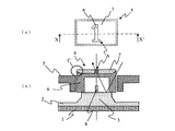
- FIG. 2A and 2B are schematic configuration diagrams showing an embodiment of a key button according to the present invention, in which FIG. 2A is a top view and FIG. 2B is a cross-sectional view taken along the line XX ′ of FIG.
- a rubber contact switch 2 is provided on the substrate 1.
- the rubber contact switch 2 has a switch portion 3 that protrudes in the opposite direction to the substrate 1.
- a key button 4 that is a hollow solid body and has a character portion A that protrudes in the opposite direction to the switch unit 3, that is, toward the outside (in the opposite direction to the hollow portion). It has been.
- the key button 4 includes a transmissive portion 6 made of a material that transmits light and a portion other than the character portion A on the surface of the transmissive portion 6 on which the character portion A is formed. It is comprised with the shielding part 7 which covers.
- the key button 4 is surrounded by the housing 5.
- the surface provided with the character part A is a display surface for allowing the user to recognize the character.
- a backlight 8 such as an LED (Light Emitting Diode) is provided inside the key button 4.
- the key button 4 Since the key button 4 is surrounded by the housing 5, the movement in the horizontal direction is restricted with respect to the surface having the character part A of the key button 4, and the key button 4 is movable in the vertical direction.
- the key button 4 pushes the switch part 3 of the rubber contact switch 2 into the substrate 1 side.
- substrate 1 contact, and a signal is sent.
- the related-art key button 14 is hollow, and the three-dimensional transmission part 16 having the character part B protruding outward is covered with the shielding part 17 except for the character part B. .
- the shielding part 7 of the key button 4 of the present invention covers the part other than the character part A on the surface of the transmissive part 6 where the character part A is formed. Therefore, surfaces other than the surface on which the character portion A of the transmissive portion 6 is formed are not covered with the shielding portion 7. Further, the surface of the transmissive portion 6 that is in contact with the shielding portion 7 is positioned higher than the surface of the housing 5 opposite to the substrate 1, that is, the outer surface. Therefore, a part of the side surface extending in the direction intersecting the display surface (orthogonal direction in the example shown in FIG. 2) is exposed without being covered by the shielding part 7 or the housing 5. This portion serves as an entrance through which light enters the inside of the transmissive portion 6 of the key button 4 from the outside.
- the material that transmits light may be a transparent resin material, and the material that substantially blocks light may be a black resin material. However, it is not limited to this.
- the key button 4 of the present invention has light that enters from the outside to the inside of the key button 4 even if the shielding portion 7 has a color that greatly shields light such as black.
- the light reflected inside can be emitted from the character portion A. Therefore, even when the backlight 8 is not used, the character part A can be recognized.
- the transparent portion 6 of the key button 4 has a hollow structure, but the backlight 8 may be provided behind the key button 4 instead of inside the key button 4.
- the character portion A is not projected from the surface of the transmissive portion 6, but the surface of the transmissive portion 6 on which the character portion A is provided is also flat so that only the portion of the character portion A is not covered with the shielding portion 7. May be formed.
- the key button 4 of the present invention does not use a special manufacturing apparatus, and can be molded by two-color molding with a normal injection molding machine, so that the manufacturing cost does not increase significantly.
- the key button 4 of the present invention may be formed by a method other than two-color molding.
- the key button 4 of the present invention is not limited to a key button for a communication device such as a telephone, and may be any one as long as the key button 4 of the present invention can be applied.
Landscapes
- Push-Button Switches (AREA)
Abstract
Description
Claims (5)
- 前記文字部が設けられた1つの表示面と、前記表示面に対して交差する方向に延びる側面と、を形成する、光を透過させる材料で構成された透過部と、
前記透過部の、前記表示面の前記文字部以外の部分のみを覆っている、光を遮蔽する材料で形成された遮蔽部と、を有する、キーボタン。 - 前記キーボタンの前記透過部は、内部にバックライトが設けられた中空部を有し、前記文字部は前記中空部とは逆向きに前記透過部の表面から突出して形成されている、請求項1に記載のキーボタン。
- 前記文字部の設けられている面の外周端部において、前記遮蔽部の前記透過部と接している面は、前記透過部と接している面と反対の面側に屈折している、請求項1または2に記載のキーボタン。
- 請求項1から3のいずれか1項に記載のキーボタンと、該キーボタンを囲んでいるハウジングとを有しており、
前記表示面に対して直交する方向において、前記透過部の前記遮蔽部と接している面が、前記ハウジングの外面よりも外側に位置している、キーボタンを有する機器。 - 表示面に設けられた文字部と、前記表示面に対して交差する方向に延びる側面とを、光を透過させる材料で形成しておき、前記表示面の前記文字部以外の部分を、光を遮蔽する材料で覆うステップと、
前記キーボタンの外部の光を、前記側面の透過部から進入させて、前記表示面の前記文字部から放出させるステップと、を有する、キーボタンの文字表示方法。
Priority Applications (6)
| Application Number | Priority Date | Filing Date | Title |
|---|---|---|---|
| US13/577,319 US9691572B2 (en) | 2010-02-18 | 2011-01-19 | Key button |
| EP11744463.8A EP2538427B1 (en) | 2010-02-18 | 2011-01-19 | Keybutton |
| CA2790005A CA2790005C (en) | 2010-02-18 | 2011-01-19 | Key button |
| CN2011800101098A CN102754174B (zh) | 2010-02-18 | 2011-01-19 | 键钮 |
| AU2011216712A AU2011216712B2 (en) | 2010-02-18 | 2011-01-19 | Key button |
| HK13100834.5A HK1173844B (en) | 2010-02-18 | 2011-01-19 | Key button |
Applications Claiming Priority (2)
| Application Number | Priority Date | Filing Date | Title |
|---|---|---|---|
| JP2010033592A JP4888797B2 (ja) | 2010-02-18 | 2010-02-18 | キーボタン |
| JP2010-033592 | 2010-02-18 |
Publications (1)
| Publication Number | Publication Date |
|---|---|
| WO2011102174A1 true WO2011102174A1 (ja) | 2011-08-25 |
Family
ID=44482776
Family Applications (1)
| Application Number | Title | Priority Date | Filing Date |
|---|---|---|---|
| PCT/JP2011/050861 Ceased WO2011102174A1 (ja) | 2010-02-18 | 2011-01-19 | キーボタン |
Country Status (7)
| Country | Link |
|---|---|
| US (1) | US9691572B2 (ja) |
| EP (1) | EP2538427B1 (ja) |
| JP (1) | JP4888797B2 (ja) |
| CN (1) | CN102754174B (ja) |
| AU (1) | AU2011216712B2 (ja) |
| CA (1) | CA2790005C (ja) |
| WO (1) | WO2011102174A1 (ja) |
Cited By (2)
| Publication number | Priority date | Publication date | Assignee | Title |
|---|---|---|---|---|
| CN104303247A (zh) * | 2012-05-09 | 2015-01-21 | 矢崎总业株式会社 | 显示开关 |
| US9484165B2 (en) | 2012-05-31 | 2016-11-01 | Yazaki Corporation | Illumination display switching device |
Families Citing this family (7)
| Publication number | Priority date | Publication date | Assignee | Title |
|---|---|---|---|---|
| JP6004701B2 (ja) * | 2012-03-30 | 2016-10-12 | 三菱重工業株式会社 | 表示装置およびこれを備えた車両用空調装置 |
| JP6102665B2 (ja) * | 2013-09-30 | 2017-03-29 | オムロン株式会社 | 操作ユニットおよび遊技機 |
| US9395822B2 (en) | 2014-03-03 | 2016-07-19 | Peter Hinz | Keycap including a liquid crystal panel and polarizing glyphs |
| US10515508B2 (en) | 2017-09-14 | 2019-12-24 | Ags Llc | Push-buttons for gaming machines |
| DE102018127894B4 (de) * | 2018-03-09 | 2025-01-02 | Seoyon America Corp. | Weiche obere Verkleidung für eine Schalterbaugruppe einer Fahrzeugtür und Verfahren zum Herstellen dieser |
| EP3762954B1 (en) | 2019-05-28 | 2025-07-02 | Google LLC | Button with illumination ring |
| KR102369965B1 (ko) * | 2020-12-24 | 2022-03-03 | 주식회사 수인산업 | 이중사출을 이용한 투광버튼의 제조방법 및 그 버튼 |
Citations (3)
| Publication number | Priority date | Publication date | Assignee | Title |
|---|---|---|---|---|
| JPS6376929U (ja) * | 1986-11-08 | 1988-05-21 | ||
| JP2004338183A (ja) | 2003-05-14 | 2004-12-02 | Uniden Corp | キートップの二色成形方法 |
| JP2010033592A (ja) | 2005-02-14 | 2010-02-12 | Panasonic Corp | アプリケーション実行装置、管理方法、プログラム |
Family Cites Families (14)
| Publication number | Priority date | Publication date | Assignee | Title |
|---|---|---|---|---|
| JPS6376929A (ja) * | 1986-09-19 | 1988-04-07 | Sony Corp | ト−シヨンバネ装置 |
| JPH0233816A (ja) * | 1988-07-21 | 1990-02-05 | Alps Electric Co Ltd | キートップ |
| JP2767312B2 (ja) * | 1990-04-18 | 1998-06-18 | 日本シイエムケイ株式会社 | プリント配線板における電磁波シールド層とアース回路の接続方法 |
| US5510782A (en) * | 1992-08-03 | 1996-04-23 | Itt Corporation | Back lit keypad |
| US5718326A (en) * | 1996-07-22 | 1998-02-17 | Delco Electronics Corporation | Backlit button/switchpad assembly |
| US5993019A (en) * | 1997-10-03 | 1999-11-30 | Delco Electronics Corporation | Molded two part button with illuminated graphic |
| JP4295468B2 (ja) | 2001-12-21 | 2009-07-15 | ポリマテック株式会社 | 照光式押釦スイッチ用カバー部材 |
| JP2004002008A (ja) | 2002-03-29 | 2004-01-08 | Toshiba Elevator Co Ltd | エレベータの操作ボタン装置 |
| US7073916B2 (en) * | 2002-04-29 | 2006-07-11 | Hewlett-Packard Development Company, L.P. | Key for use in low light conditions |
| JP4100059B2 (ja) | 2002-07-01 | 2008-06-11 | 日本電気株式会社 | 携帯端末用キーボタンおよび携帯端末 |
| JP2004193891A (ja) | 2002-12-10 | 2004-07-08 | Mitsubishi Electric Corp | 携帯無線電話機 |
| US7105759B1 (en) | 2005-06-28 | 2006-09-12 | Tektronix, Inc. | Instrument with illuminated control knob |
| EP1761002B1 (en) * | 2005-08-30 | 2013-12-18 | LG Electronics Inc. | Touch key assembly for a mobile terminal |
| JP2009181893A (ja) | 2008-01-31 | 2009-08-13 | Kyocera Corp | 小型電子機器 |
-
2010
- 2010-02-18 JP JP2010033592A patent/JP4888797B2/ja active Active
-
2011
- 2011-01-19 AU AU2011216712A patent/AU2011216712B2/en active Active
- 2011-01-19 WO PCT/JP2011/050861 patent/WO2011102174A1/ja not_active Ceased
- 2011-01-19 US US13/577,319 patent/US9691572B2/en active Active
- 2011-01-19 CN CN2011800101098A patent/CN102754174B/zh active Active
- 2011-01-19 EP EP11744463.8A patent/EP2538427B1/en active Active
- 2011-01-19 CA CA2790005A patent/CA2790005C/en active Active
Patent Citations (3)
| Publication number | Priority date | Publication date | Assignee | Title |
|---|---|---|---|---|
| JPS6376929U (ja) * | 1986-11-08 | 1988-05-21 | ||
| JP2004338183A (ja) | 2003-05-14 | 2004-12-02 | Uniden Corp | キートップの二色成形方法 |
| JP2010033592A (ja) | 2005-02-14 | 2010-02-12 | Panasonic Corp | アプリケーション実行装置、管理方法、プログラム |
Non-Patent Citations (1)
| Title |
|---|
| See also references of EP2538427A4 * |
Cited By (5)
| Publication number | Priority date | Publication date | Assignee | Title |
|---|---|---|---|---|
| CN104303247A (zh) * | 2012-05-09 | 2015-01-21 | 矢崎总业株式会社 | 显示开关 |
| US20150043193A1 (en) * | 2012-05-09 | 2015-02-12 | Yazaki Corporation | Display switch |
| US9659719B2 (en) * | 2012-05-09 | 2017-05-23 | Yazaki Corporation | Display switch |
| US9484165B2 (en) | 2012-05-31 | 2016-11-01 | Yazaki Corporation | Illumination display switching device |
| CN104380414B (zh) * | 2012-05-31 | 2017-06-13 | 矢崎总业株式会社 | 照明显示开关装置 |
Also Published As
| Publication number | Publication date |
|---|---|
| JP4888797B2 (ja) | 2012-02-29 |
| JP2011171106A (ja) | 2011-09-01 |
| AU2011216712A1 (en) | 2012-07-19 |
| CN102754174B (zh) | 2013-12-04 |
| EP2538427A1 (en) | 2012-12-26 |
| CN102754174A (zh) | 2012-10-24 |
| CA2790005A1 (en) | 2011-08-25 |
| CA2790005C (en) | 2013-08-06 |
| HK1173844A1 (en) | 2013-05-24 |
| EP2538427B1 (en) | 2016-03-30 |
| EP2538427A4 (en) | 2014-04-02 |
| US9691572B2 (en) | 2017-06-27 |
| AU2011216712B2 (en) | 2015-03-12 |
| US20120307479A1 (en) | 2012-12-06 |
Similar Documents
| Publication | Publication Date | Title |
|---|---|---|
| JP4888797B2 (ja) | キーボタン | |
| KR102075462B1 (ko) | 표시장치 및 이를 갖는 이동단말기 | |
| US9837228B2 (en) | Illuminated keyboard with optical switch | |
| JP6124390B2 (ja) | 照光式押釦スイッチ | |
| US10469081B2 (en) | Split type dual optical path key switch and a mechanical keyboard | |
| KR101275388B1 (ko) | 광포인팅 모듈 및 전자 장치 | |
| WO2013021987A1 (ja) | 導光モジュール及びこれを備える電子機器 | |
| KR101053369B1 (ko) | 조명 기능을 갖는 광포인팅 모듈 및 전자 장치 | |
| JP5211168B2 (ja) | 入力装置 | |
| JP7253569B2 (ja) | 装置 | |
| US8680413B2 (en) | Illuminating push-button device and portable terminal | |
| TWI603354B (zh) | 按鍵結構及應用按鍵結構的電子裝置 | |
| JP2007080763A (ja) | 照光式押釦スイッチ用カバー部材及びその製造方法 | |
| HK1173844B (en) | Key button | |
| CN206629097U (zh) | 导光组件、发光组件、按键组件及移动终端 | |
| JP2009220929A (ja) | エレベータの防滴型押しボタンスイッチ | |
| JP2009181893A (ja) | 小型電子機器 | |
| KR20080099930A (ko) | 투명 전도성 접점 구조를 갖는 키패드 및 그 제조방법 | |
| JP2001076572A (ja) | 防水スイッチ構造 | |
| JP2010049812A (ja) | キースイッチ構造体 | |
| CN220102944U (zh) | 交互装置及控制柜 | |
| CN202178187U (zh) | 发光按键的发光件外罩 | |
| JP2010027568A (ja) | キースイッチ構造体 | |
| WO2018158932A1 (ja) | 基板支持装置およびスマートキー | |
| JP2008034121A (ja) | スイッチ装置 |
Legal Events
| Date | Code | Title | Description |
|---|---|---|---|
| WWE | Wipo information: entry into national phase |
Ref document number: 201180010109.8 Country of ref document: CN |
|
| 121 | Ep: the epo has been informed by wipo that ep was designated in this application |
Ref document number: 11744463 Country of ref document: EP Kind code of ref document: A1 |
|
| WWE | Wipo information: entry into national phase |
Ref document number: 2011216712 Country of ref document: AU |
|
| ENP | Entry into the national phase |
Ref document number: 2011216712 Country of ref document: AU Date of ref document: 20110119 Kind code of ref document: A |
|
| WWE | Wipo information: entry into national phase |
Ref document number: 13577319 Country of ref document: US |
|
| ENP | Entry into the national phase |
Ref document number: 2790005 Country of ref document: CA |
|
| WWE | Wipo information: entry into national phase |
Ref document number: 2011744463 Country of ref document: EP |
|
| NENP | Non-entry into the national phase |
Ref country code: DE |