WO2011102316A1 - ガス濃度算出装置及びガス濃度計測モジュール - Google Patents
ガス濃度算出装置及びガス濃度計測モジュール Download PDFInfo
- Publication number
- WO2011102316A1 WO2011102316A1 PCT/JP2011/053041 JP2011053041W WO2011102316A1 WO 2011102316 A1 WO2011102316 A1 WO 2011102316A1 JP 2011053041 W JP2011053041 W JP 2011053041W WO 2011102316 A1 WO2011102316 A1 WO 2011102316A1
- Authority
- WO
- WIPO (PCT)
- Prior art keywords
- light
- gas
- gas concentration
- light source
- light receiving
- Prior art date
- Legal status (The legal status is an assumption and is not a legal conclusion. Google has not performed a legal analysis and makes no representation as to the accuracy of the status listed.)
- Ceased
Links
Images












Classifications
-
- G—PHYSICS
- G01—MEASURING; TESTING
- G01N—INVESTIGATING OR ANALYSING MATERIALS BY DETERMINING THEIR CHEMICAL OR PHYSICAL PROPERTIES
- G01N21/00—Investigating or analysing materials by the use of optical means, i.e. using sub-millimetre waves, infrared, visible or ultraviolet light
- G01N21/17—Systems in which incident light is modified in accordance with the properties of the material investigated
- G01N21/25—Colour; Spectral properties, i.e. comparison of effect of material on the light at two or more different wavelengths or wavelength bands
- G01N21/31—Investigating relative effect of material at wavelengths characteristic of specific elements or molecules, e.g. atomic absorption spectrometry
- G01N21/35—Investigating relative effect of material at wavelengths characteristic of specific elements or molecules, e.g. atomic absorption spectrometry using infrared light
- G01N21/3504—Investigating relative effect of material at wavelengths characteristic of specific elements or molecules, e.g. atomic absorption spectrometry using infrared light for analysing gases, e.g. multi-gas analysis
-
- G—PHYSICS
- G01—MEASURING; TESTING
- G01N—INVESTIGATING OR ANALYSING MATERIALS BY DETERMINING THEIR CHEMICAL OR PHYSICAL PROPERTIES
- G01N21/00—Investigating or analysing materials by the use of optical means, i.e. using sub-millimetre waves, infrared, visible or ultraviolet light
- G01N21/01—Arrangements or apparatus for facilitating the optical investigation
- G01N21/03—Cuvette constructions
- G01N21/0303—Optical path conditioning in cuvettes, e.g. windows; adapted optical elements or systems; path modifying or adjustment
-
- G—PHYSICS
- G01—MEASURING; TESTING
- G01N—INVESTIGATING OR ANALYSING MATERIALS BY DETERMINING THEIR CHEMICAL OR PHYSICAL PROPERTIES
- G01N21/00—Investigating or analysing materials by the use of optical means, i.e. using sub-millimetre waves, infrared, visible or ultraviolet light
- G01N21/01—Arrangements or apparatus for facilitating the optical investigation
- G01N21/03—Cuvette constructions
- G01N21/05—Flow-through cuvettes
-
- G—PHYSICS
- G01—MEASURING; TESTING
- G01N—INVESTIGATING OR ANALYSING MATERIALS BY DETERMINING THEIR CHEMICAL OR PHYSICAL PROPERTIES
- G01N21/00—Investigating or analysing materials by the use of optical means, i.e. using sub-millimetre waves, infrared, visible or ultraviolet light
- G01N21/17—Systems in which incident light is modified in accordance with the properties of the material investigated
- G01N21/25—Colour; Spectral properties, i.e. comparison of effect of material on the light at two or more different wavelengths or wavelength bands
- G01N21/27—Colour; Spectral properties, i.e. comparison of effect of material on the light at two or more different wavelengths or wavelength bands using photo-electric detection ; circuits for computing concentration
-
- G—PHYSICS
- G01—MEASURING; TESTING
- G01N—INVESTIGATING OR ANALYSING MATERIALS BY DETERMINING THEIR CHEMICAL OR PHYSICAL PROPERTIES
- G01N21/00—Investigating or analysing materials by the use of optical means, i.e. using sub-millimetre waves, infrared, visible or ultraviolet light
- G01N21/17—Systems in which incident light is modified in accordance with the properties of the material investigated
- G01N21/59—Transmissivity
- G01N21/61—Non-dispersive gas analysers
-
- G—PHYSICS
- G02—OPTICS
- G02B—OPTICAL ELEMENTS, SYSTEMS OR APPARATUS
- G02B26/00—Optical devices or arrangements for the control of light using movable or deformable optical elements
- G02B26/08—Optical devices or arrangements for the control of light using movable or deformable optical elements for controlling the direction of light
- G02B26/0816—Optical devices or arrangements for the control of light using movable or deformable optical elements for controlling the direction of light by means of one or more reflecting elements
Definitions
- the present invention relates to a gas concentration calculation device and a gas concentration measurement module.
- a gas concentration calculation device for calculating the concentration of gas such as carbon dioxide has been introduced in the field of air conditioning systems.
- the air conditioning system is operated efficiently and power consumption is reduced by controlling ventilation ON / OFF based on the calculation result of the gas concentration calculation device.
- the NDIR (Non-dispersive Infrared) method is used in such a gas concentration calculation device, and in the NDIR (non-dispersive infrared absorption) method, infrared light passes through the target gas. This is a technique for calculating the concentration of gas based on the attenuation.
- This gas concentration calculation apparatus irradiates light from a single light source into a gas cell, and detects light passing through the gas cell by a first detector and a second detector.
- the first detector detects light that has passed through an optical path including a measurement gas region and an inert gas region sealed in the measurement gas chamber.
- the second detector detects light that has passed through an optical path including a measured gas region and a gas region of the same type as the measured gas sealed in the comparison gas chamber. Further, it is disclosed that an increase or decrease in the amount of irradiation light is detected by a second detector and the output of the first detector is calibrated.
- Patent Document 2 describes a gas concentration calculation device that detects the concentration of sample gas in a cylinder.
- a reflecting mirror is provided on the head of the piston that reciprocates in the cylinder, and a light source and a detector are arranged in the cylinder head toward the inside of the cylinder.
- JP 2007-256242 A Japanese Patent Laid-Open No. 5-180760
- the gas concentration is calculated using two separate light receiving elements, the first detector and the second detector. For this reason, individual differences in the light receiving elements themselves (sensitivity, noise characteristics, differences with respect to ambient temperature, differences with respect to long-term changes, etc.) adversely affect the gas concentration measurement accuracy. Since such an adverse effect is due to individual differences between the light receiving elements, it is not canceled by using the ratio of output values from both light receiving elements.
- one aspect of the present invention has been made in view of the above, and a gas concentration calculation device and a gas that can prevent a problem due to individual differences in light receiving elements and a problem due to an unstable optical path length.
- An object is to provide a concentration measurement module.
- Another aspect of the present invention prevents problems due to individual differences in light receiving elements, prevents a decrease in light detection accuracy due to vibrations of elements for changing the optical path length, and further due to a shift in light measurement time. It is an object of the present invention to provide a gas concentration calculation device and a gas concentration measurement module capable of suppressing a decrease in light detection accuracy.
- Another aspect of the present invention is to prevent a malfunction due to an element for changing the optical path length moving in the same direction as the direction of the optical path.
- An object of the present invention is to provide a gas concentration calculation device and a gas concentration measurement module capable of performing the above.
- a gas concentration calculation apparatus includes a gas concentration measurement module and a gas concentration calculation module, and calculates a concentration of a target gas, the gas concentration calculation apparatus
- the measurement module includes a gas cell forming an introduction space into which the target gas is introduced, a light source disposed at one end of the gas cell, and light emitted from the light source disposed at the one end or the other end of the gas cell.
- Reflection switching means for reflecting or transmitting, reflection means for reflecting the light transmitted through the reflection switching means, and a predetermined comparison gas are enclosed, and disposed on the optical path of the light transmitted through the reflection switching means
- a light receiving means for receiving the light emitted from the light source, passing through the reflection switching means, passing through the comparison gas cell, and reflected by the reflection means, and the gas concentration calculation module comprises: The concentration of the target gas is calculated based on the light reception energy value of the light receiving means when light is reflected and transmitted by the reflection switching means.
- a gas concentration measurement module is a gas concentration measurement module in a gas concentration calculation device that calculates the concentration of a target gas, the gas cell forming an introduction space into which the target gas is introduced, A light source disposed at one end of the gas cell, a reflection switching unit disposed at the one end or the other end of the gas cell, which reflects or transmits light emitted from the light source, and reflects light transmitted through the reflection switching unit.
- the light receiving means receives both the light reflected by the reflection switching means and the light transmitted through the reflection switching means and passed through the comparison gas cell. For this reason, inconveniences due to individual differences in the light receiving means when the light is separately received by the different light receiving means when the reflection switching means is switched between reflection and transmission are prevented. Further, since the reflection switching means is arranged at one end or the other end of the gas cell into which the target gas is introduced, that is, the reflection switching means is arranged outside the gas cell, so that reflection and transmission are switched by the reflection switching means. There is no change in the optical path length through which each light passes through the target gas in the gas cell. For this reason, the malfunction by the optical path length of the light which passes in the object gas being unstable can be prevented.
- the reflection switching unit is a reflectance adjustment unit that electrically adjusts the reflectance with respect to light emitted from the light source to switch between reflection and transmission of light.
- the means for generating a difference in the light receiving energy value in the light received by the light receiving means is the reflectance adjusting means, and the operation of the reflectance adjusting means is based on the electrical control of the reflectance. Therefore, there is no vibration or the like in order to generate a difference in received light energy value, and there is no position shift or additional noise due to the vibration, so that it is possible to prevent the light detection accuracy of the gas concentration measurement module from being lowered.
- the reflectance can be switched at a high speed by the reflectance adjusting means electrically controlling the reflectance. Therefore, it is as if there is no time lag in the light measurement timing received by the light receiving means, or even if it is very short, pseudo-simultaneous measurement is possible.
- a spatial light modulator (SLM) or a liquid crystal optical element is suitable as the reflectance adjusting means for providing such an effect.
- the reflection switching means is a rotation mechanism that switches between reflection and transmission by rotation of light emitted from the light source.
- the means for generating the difference in the light receiving energy value in the light received by the light receiving means is a rotating mechanism, and the rotating mechanism is arranged outside the gas cell even if the rotating mechanism is rotating. Therefore, there is no change in the optical path length through which each light passes through the target gas in the gas cell when reflection and transmission are switched. Therefore, unlike the case of Patent Document 2, for example, the optical path length is stable, so there is no need to temporarily stop the rotation mechanism. As a result, it is possible to prevent problems such as a significant time shift in the light measurement timing due to the temporary movement stop of the rotation mechanism.
- the rotating mechanism may be constituted by a rotating mirror composed of a reflector and a hole.
- the reflection means includes a plurality of reflection surfaces having different angles, and the light transmitted through the reflection switching means is sequentially reflected by the plurality of reflection surfaces and is reflected for each reflection on the reflection surface. It is preferable to pass through the comparative gas cell.
- the optical path passing through the comparison gas cell can be lengthened. For this reason, the characteristic of the light radiated
- the optical path length of the light passing through the comparison gas cell can be increased by a small comparison gas cell without increasing the size of the comparison gas cell.
- the predetermined reference gas is preferably a saturated gas of the same type as the target gas.
- a difference in light reception energy value by the light receiving means can be generated by utilizing a change in characteristics when light passes through the same kind of saturated gas as the target gas.
- a band-pass filter that is disposed on an optical path between the light source and the light receiving means and allows only light having a predetermined wavelength to pass therethrough.
- the wavelength band of the received light can be made the same wavelength band by the band pass filter, and it is possible to prevent a decrease in light detection accuracy due to the reception of light of different wavelength bands.
- the light source emits infrared rays.
- the concentration of the target gas can be calculated using a phenomenon in which energy is attenuated when infrared rays pass through the target gas.
- the target gas is preferably carbon dioxide.
- the concentration of the target gas can be calculated using a phenomenon in which energy is attenuated when light passes through carbon dioxide.
- the gas concentration measuring module including a plurality of the light receiving units having different target gases and the gas concentration calculating modules corresponding to the plurality of light receiving units.
- the band pass filter on the front surface of the light receiving unit. Further, by providing a plurality of gas concentration measurement modules having different target gases, the concentrations of the plurality of gases can be calculated simultaneously with high accuracy.
- a gas concentration calculation apparatus includes a gas concentration measurement module and a gas concentration calculation module, and is a gas concentration calculation apparatus that calculates the concentration of a target gas
- the gas concentration measurement module includes: A gas cell that forms an introduction space into which the target gas is introduced, a light source disposed in the gas cell, and a reflection that is disposed at one end of the gas cell and electrically adjusts the reflectance of light emitted from the light source.
- a rate adjusting means, and a light receiving means that is disposed at the other end of the gas cell and receives the direct light directly emitted from the light source and the reflected light emitted from the light source and reflected by the reflectance adjusting means.
- the gas concentration calculation module includes the light receiving hand in each case where the reflectance is electrically adjusted by the reflectance adjusting means. Based on the ratio of the light receiving energy value, to calculate the concentration of the target gas, characterized in that.
- a gas concentration measurement module is a gas concentration measurement module in a gas concentration calculation device that calculates the concentration of a target gas, and a gas cell that forms an introduction space into which the target gas is introduced;
- a light source disposed in the gas cell;
- a reflectance adjusting means disposed at one end of the gas cell to electrically adjust a reflectance with respect to light emitted from the light source; and disposed at the other end of the gas cell;
- light receiving means for receiving the direct light emitted directly from the light source and the reflected light emitted from the light source and reflected by the reflectance adjusting means.
- the light receiving means since the light receiving means receives both the direct light and the reflected light, the direct light and the reflected light are received by different light receiving means, When the reflectance is electrically adjusted by the reflectance adjusting means, the light due to the individual difference of the light receiving means when the light is separately received by the different light receiving means is prevented.
- the means for generating a change in the optical path length or a difference in the light receiving energy value in the light received by the light receiving means is a reflectance adjusting means, and the operation of the reflectance adjusting means is an electrical function of the reflectance. Control. Therefore, there is no vibration to generate a change in the optical path length or a difference in the received light energy value, and there is no position shift or additional noise due to the vibration, preventing a decrease in the light detection accuracy of the gas concentration measurement module. it can.
- the reflectance can be switched at high speed by the reflectance adjusting means electrically controlling the reflectance. Therefore, it is as if there is no time lag in the light measurement timing received by the light receiving means, or even if it is very short, pseudo-simultaneous measurement is possible.
- An electro-optical device or a liquid crystal optical element is suitable as the reflectance adjusting means that brings about such an effect.
- a band-pass filter that is disposed on an optical path between the light source and the light receiving means and allows only light having a predetermined wavelength to pass therethrough.
- the wavelength band of the received light can be made the same wavelength band by the band pass filter, and it is possible to prevent a decrease in light detection accuracy due to the reception of light of different wavelength bands.
- the light source emits infrared rays.
- the concentration of the target gas can be calculated using a phenomenon in which energy is attenuated when infrared rays pass through the target gas.
- the target gas is preferably carbon dioxide.
- the concentration of the target gas can be calculated using a phenomenon in which energy is attenuated when light passes through carbon dioxide.
- the present invention further comprises storage means for previously storing a database or an approximate expression indicating the correlation between the concentration of the target gas and the ratio, and the gas concentration calculation module includes the database or the approximate expression. Based on this, it is preferable to calculate the concentration corresponding to the ratio.
- the concentration of the target gas can be accurately calculated based on a database or approximate expression prepared in advance.
- the gas concentration measuring module including a plurality of the light receiving units having different target gases and the gas concentration calculating modules corresponding to the plurality of light receiving units.
- the present invention by providing a plurality of gas concentration measurement modules having different target gases, it is possible to calculate the concentrations of a plurality of gases at the same time with high accuracy.
- a gas concentration calculation device includes a gas concentration measurement module and a gas concentration calculation module, and is a gas concentration calculation device that calculates the concentration of a target gas
- the gas concentration measurement module includes: A gas cell that forms an introduction space into which the target gas is introduced, a light source disposed in the gas cell, and a rotation mechanism that is disposed at one end of the gas cell and reflects or transmits light emitted from the light source by rotation.
- a light receiving means that is disposed at the other end of the gas cell and receives the direct light emitted directly from the light source and the reflected light emitted from the light source and reflected by the rotating mechanism, and the gas concentration
- the calculation module is configured to receive light reception energy of the light receiving unit when the light is reflected or transmitted by the rotation mechanism. Based on the ratio of, calculate the concentration of the target gas, wherein the rotation mechanism performs the rotation in different directions the direction of the light path from the light source to the light receiving means, characterized in that.
- a gas concentration measurement module is a gas concentration measurement module in a gas concentration calculation device that calculates the concentration of a target gas, and forms a gas introduction space into which the target gas is introduced.
- a light source disposed in the gas cell; a rotation mechanism disposed at one end of the gas cell that reflects or transmits light emitted from the light source by rotation; and a light source disposed at the other end of the gas cell.
- the light receiving means since the light receiving means receives both the direct light and the reflected light, the direct light and the reflected light are received by different light receiving means, Problems caused by individual differences in the light receiving means when light received by the rotating mechanism is separately received by different light receiving means are prevented.
- the means for generating the difference in the optical path length and the difference in the light reception energy value in the light received by the light receiving means is a rotating mechanism, and this rotating mechanism is different from the direction of the optical path from the light source to the light receiving means.
- rotating in the direction By rotating in the direction, light is reflected or transmitted.
- “rotation in a direction different from the direction of the optical path” can be achieved, for example, by setting the rotation axis of the rotation mechanism in the same direction as the optical path. In other words, it is not necessary for the rotating mechanism to move along the direction of the optical path in order to generate a change in the optical path length or a difference in the received light energy value. Therefore, even if the rotating mechanism is rotating, There is no change in the absolute distance to the light receiving means.
- the optical path length is stable, so there is no need to temporarily stop the rotation mechanism. As a result, it is possible to prevent a significant time shift from occurring in the light measurement timing due to the temporary movement stop of the rotation mechanism.
- the rotation mechanism may be constituted by a rotating mirror including a reflector and a hole.
- a simple configuration is possible with a rotating mirror consisting of a reflector and a hole.
- the rotating mirror may perform the rotation in a direction substantially perpendicular to the direction of the optical path from the light source to the light receiving means.
- the rotating mirror can be rotated in a direction substantially perpendicular to the direction of the optical path. Thereby, reflection and transmission of light can be switched clearly.
- the rotation mechanism may be constituted by a micro electro mechanical system (MEMS) actuator and a mirror.
- MEMS micro electro mechanical system
- the MEMS actuator by using the MEMS actuator, high-speed rotation is possible while suppressing vibration during rotation. Therefore, it is possible to prevent a decrease in light detection accuracy due to vibration. Moreover, the high-speed rotation of the MEMS actuator allows the light to be switched between reflection and transmission at high speed, and it is as if there is no time lag in the light measurement timing of the light receiving means. Measurement is possible.
- a band-pass filter that is disposed on an optical path between the light source and the light receiving means and allows only light having a predetermined wavelength to pass therethrough.
- the wavelength band of the received light can be made the same wavelength band by the band pass filter, and it is possible to prevent a decrease in light detection accuracy due to the reception of light of different wavelength bands.
- the light source emits infrared rays.
- the concentration of the target gas can be calculated using a phenomenon in which energy is attenuated when infrared rays pass through the target gas.
- the target gas is preferably carbon dioxide.
- the concentration of the target gas can be calculated using a phenomenon in which energy is attenuated when light passes through carbon dioxide.
- the gas is not limited to carbon dioxide. Furthermore, it is possible to measure a plurality of gases by increasing only the bandpass and the light receiving section.
- the present invention further comprises storage means for previously storing a database or an approximate expression indicating the correlation between the concentration of the target gas and the ratio, and the gas concentration calculation module includes the database or the approximate expression. Based on this, it is preferable to calculate the concentration corresponding to the ratio.
- the concentration of the target gas can be accurately calculated based on a database or approximate expression prepared in advance.
- the gas concentration measuring module including a plurality of the light receiving units having different target gases and the gas concentration calculating modules corresponding to the plurality of light receiving units.
- the present invention by providing a plurality of gas concentration measurement modules having different target gases, it is possible to calculate the concentrations of a plurality of gases at the same time with high accuracy.
- a gas concentration calculation device and a gas concentration measurement module capable of preventing a malfunction due to individual differences in light receiving elements and preventing a malfunction due to an unstable optical path length. it can.
- a gas concentration capable of preventing problems due to individual differences in light receiving means and problems due to movement of an element for changing the optical path length in the same direction as the direction of the optical path.
- a calculation device and a gas concentration measurement module can be provided.
- the modulation mirror 70X is disposed at one end of the gas cell 10X (the side where the infrared light source 20X is disposed).
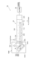
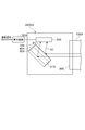
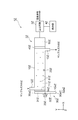
- FIG. 1 is a schematic cross-sectional view showing a gas concentration calculation device 1X.
- the gas concentration calculation device 1X receives light from an infrared light source 20X (corresponding to the “light source” in the claims) and measures the energy value thereof, and the measurement by the gas concentration measurement module 2X.
- a calculation circuit 3X that calculates a gas concentration based on the result (corresponding to a “gas concentration calculation module” in the claims), and calculates the concentration of the target gas.
- the gas concentration calculated by the calculation circuit 3X is output to a control device (not shown) or the like, and is used for controlling an air conditioning system, for example.
- a control device not shown
- an example in which carbon dioxide in the sample gas 50X introduced into the gas concentration measurement module 2X is used as a concentration calculation target gas will be described.
- the gas concentration measurement module 2X includes a gas cell 10X, a reflection switching unit 100X including an infrared light source 20X, and a light receiving unit 30X (corresponding to “light receiving means” in the claims).
- the gas cell 10X forms an introduction space 11X into which the sample gas 50X is introduced.
- the gas cell 10X is provided with a gas introduction part 12X for introducing the sample gas 50X into the introduction space 11X on one end side of the gas cell 10X, and the sample gas 50X in the introduction space 11X is externally connected to the other end side of the gas cell 10X.
- a gas discharge part 13X is provided for discharging the gas.
- a plurality of holes provided in the inner wall (for example, the upper part or the bottom part) of the gas cell may be used as the gas introduction part 12X and the gas discharge part 13X.
- the reflection switching unit 100X is disposed at one end of the gas cell 10X, and includes an infrared light source 20X, a modulation mirror 70X (corresponding to “reflection switching means, reflectance adjustment means” in the claims), and a saturated gas 41X (claims).
- a saturated gas chamber 40X (corresponding to “comparative gas cell” in claims) and a reflecting mirror 60X (corresponding to “reflecting means” in claims) And a band pass filter 90X.
- the infrared light source 20X emits infrared light.
- an infrared light source 20X that emits light including a wavelength range of 4.2 ⁇ m to 4.3 ⁇ m is used. Infrared rays from the infrared light source 20X are absorbed and attenuated by the carbon dioxide molecules 51X in the sample gas 50X.
- the modulation mirror 70X electrically adjusts the reflectance with respect to the light emitted from the infrared light source 20X.
- the modulation mirror 70X causes the light emitted from the infrared light source 20X to be totally reflected or totally transmitted by electrically adjusting the reflectance.
- the light reflected by the modulation mirror 70X is emitted toward the light receiving unit 30X.
- a liquid crystal optical element or a spatial light modulator (SLM) is employed as the modulation mirror 70X.
- SLM spatial light modulator
- other methods for controlling the reflectance with a dielectric, a metal mesh, or the like may be used.
- the reflecting mirror 60X reflects the light transmitted through the modulation mirror 70X toward the light receiving unit 30X.
- a saturated gas chamber 40X is disposed between the modulation mirror 70X and the reflection mirror 60X. For this reason, the light transmitted through the modulation mirror 70X passes through the saturated gas 41X in the saturated gas chamber 40X and is reflected by the reflecting mirror 60X. The light reflected by the reflecting mirror 60X passes through the saturated gas 41X again, passes through the modulation mirror 70X, and enters the light receiving unit 30X.
- the saturated gas 41X enclosed in the saturated gas chamber 40X uses the same kind of saturated gas as the sample gas 50X.
- the band pass filter 90X is disposed on the optical path between the infrared light source 20X and the light receiving unit 30X, and allows only light of a predetermined wavelength to pass therethrough.
- a band pass filter 90X is used that is disposed in the reflection switching unit 100X and transmits only light in the wavelength range of 4.2 ⁇ m to 4.3 ⁇ m. Further, when the band-pass filter 90X is not provided in the reflection switching unit 100X, for example, it can be provided between the light receiving unit 30X and the gas cell 10X.
- the inside of the casing 101X of the reflection switching unit 100X is filled with, for example, an inert gas that is inactive with respect to infrared rays emitted from the infrared light source 20X or a sample gas 50X.
- the light receiving unit 30X is disposed at the other end of the gas cell 10X, and is emitted from the infrared light source 20X and reflected by the modulation mirror 70X, and emitted from the infrared light source 20X and modulated mirror. It is a light receiving element that receives both the light that has passed through 70X and passed through the saturated gas chamber 40X. That is, the single light receiving unit 30X receives both the light that has passed through the saturated gas chamber 40X and the light that has not passed through the saturated gas chamber 40X. Therefore, as compared with the case where a plurality of light receiving means are used to receive a plurality of types of light, there is no adverse effect due to individual differences of the light receiving means.
- the modulation mirror 70X when the modulation mirror 70X is controlled to reflect light, the light emitted from the infrared light source 20X is reflected by the modulation mirror 70X as shown by an optical path A indicated by an arrow in FIG. The reflected light passes through the sample gas 50X in the gas cell 10X and enters the light receiving unit 30X.
- the modulation mirror 70X when the modulation mirror 70X is controlled to transmit light, the light emitted from the infrared light source 20X passes through the modulation mirror 70X as shown by an arrow B in FIG. The light passes through the chamber 40X and is reflected by the reflecting mirror 60X. The light reflected by the reflecting mirror 60X again passes through the saturated gas chamber 40X, passes through the modulation mirror 70X, and further enters the light receiving unit 30X through the sample gas 50X in the gas cell 10X.
- the optical path length is increased by the amount of light passing through the saturated gas chamber 40X as compared with the case where the modulation mirror 70X is controlled to be in the reflection state.
- infrared rays pass through the saturated gas 41X sealed in the saturated gas chamber 40X, light energy is absorbed by the saturated gas. Therefore, when the light receiving unit 30X receives light that has passed through the saturated gas chamber 40X (when light has passed through the modulation mirror 70X), it receives light that does not pass through the saturated gas chamber 40X (with the modulation mirror 70X). Compared with the case where light is reflected, light having a lower energy value is received.
- the light reception energy value is electrically changed by the modulation mirror 70X. For this reason, it is compact and the movable part can be eliminated, and there is no adverse effect such as displacement due to vibration and additional noise, and the accuracy is improved. Furthermore, the modulation speed can be greatly increased compared to the mechanical type.
- the calculation circuit 3X calculates the concentration of carbon dioxide from the light reception energy value of the light received by the light receiving unit 30X.
- the light receiving unit 30X receives the light reception energy value of the light reflected by the modulation mirror 70X and passed only through the sample gas 50X, and the light reception energy value of the light transmitted through the modulation mirror 70X and passed through the saturated gas chamber 40X and the sample gas 50X. Are output to the calculation circuit 3X.
- the calculation circuit 3X calculates the increase / decrease in the amount of radiated light based on the light reception energy value of the light that has passed through the saturated gas chamber 40X and the sample gas 50X, and calibrates the light reception energy value of the light that has passed through only the sample gas 50X.
- the concentration of carbon dioxide in the sample gas 50X can be calculated.
- the procedure for calculating the gas concentration based on the two received light energy values can be calculated using a conventionally known gas correlation method as disclosed in, for example, Patent Document 1. Detailed description will be omitted.
- the light receiving unit 30X receives both the light reflected by the modulation mirror 70X and the light transmitted through the modulation mirror 70X and passed through the saturated gas chamber 40X. Therefore, inconvenience due to individual differences in the light receiving units 30X when the light in each case where the reflection and transmission are switched by the modulation mirror 70X is separately received by the different light receiving units 30X is prevented.
- the modulation mirror 70X is arranged at one end of the gas cell 10X into which the sample gas 50X has been introduced, that is, since the modulation mirror 70X is arranged outside the gas cell 10X, reflection and transmission are switched by the modulation mirror 70X. There is no change in the optical path length through which each light passes through the sample gas 50X. For this reason, the malfunction by the optical path length of the light which passes in the sample gas 50X being unstable can be prevented.
- the means for generating the difference in the optical path length and the difference in the light reception energy value in the light received by the light receiving unit 30X is the modulation mirror 70X, and the operation of the modulation mirror 70X is based on the reflectivity.
- electrical control Therefore, there is no vibration or the like in order to generate a difference in optical path length or a difference in received light energy value, and there is no position shift or additional noise due to the vibration. Therefore, the light detection accuracy of the gas concentration measurement module 2X is reduced. Can be prevented.
- the modulation mirror 70X electrically controls the reflectance, whereby the reflectance can be switched at a high speed. Accordingly, it is as if there is no time lag in the light measurement timing received by the light receiving unit 30X, or even if it is very short, pseudo-simultaneous measurement is possible.
- a spatial light modulator (SLM) or a liquid crystal optical element is suitable as the modulation mirror 70X that brings about such an effect.
- a difference in received light energy value by the light receiving unit 30X can be generated by using a change in characteristics when light emitted from the infrared light source 20X passes through the saturated gas 41X of the same type as the sample gas 50X. .
- the wavelength band of the received light can be made the same wavelength band by the band-pass filter 90X, and it is possible to prevent a decrease in light detection accuracy caused by receiving light of different wavelength bands.
- the concentration of carbon dioxide in the sample gas 50X can be calculated by using a phenomenon in which energy is attenuated by carbon dioxide when the infrared light source 20X emits infrared rays and the infrared rays pass through the sample gas 50X.
- the concentration of carbon dioxide in the sample gas 50X can be calculated using a phenomenon in which energy is attenuated when infrared light emitted from the infrared light source 20X passes through the carbon dioxide in the sample gas 50X.
- the type of gas that can be measured is not limited to carbon dioxide, but can be arbitrarily selected by selecting the wavelength of light to be used with a band-pass filter and using the gas as a measurement gas.
- the modulation mirror 70X is arranged on the other end side (the side where the light receiving unit 30X is arranged) of the gas cell 10X.
- the same number is attached
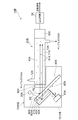
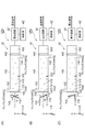
- FIG. 2 is a schematic cross-sectional view showing the gas concentration calculation apparatus 1XA.
- the gas concentration calculation device 1XA receives light from an infrared light source 20X (corresponding to the “light source” in the claims) and measures the energy value of the gas concentration measurement module 2XA and the gas concentration measurement module 2XA. And a calculation circuit 3X that calculates a gas concentration based on the result (corresponding to a “gas concentration calculation module” in the claims), and calculates the concentration of the target gas.
- the gas concentration calculated by the calculation circuit 3X is output to a control device (not shown) or the like, and is used for controlling an air conditioning system, for example.
- a control device not shown
- carbon dioxide in the sample gas 50X introduced into the gas concentration measurement module 2XA is used as a concentration calculation target gas will be described.
- the gas concentration measurement module 2XA includes a gas cell 10X, a reflection switching unit 100XA, and an infrared light source 20X.
- the infrared light source 20X is disposed at one end of the gas cell 10X and emits infrared light.
- an infrared light source 20X that emits light including a wavelength region of 4.2 ⁇ m to 4.3 ⁇ m is used. Infrared rays from the infrared light source 20X are absorbed and attenuated by the carbon dioxide molecules 51X in the sample gas 50X.
- the reflection switching unit 100XA is arranged at the other end of the gas cell 10X, and includes a light receiving unit 30X (corresponding to “light receiving means” in claims) and a modulation mirror 70X (“reflection switching means, reflectance adjustment in claims”). Means), a saturated gas chamber 40X (corresponding to “comparative gas cell” in the claims) in which a saturated gas 41X (corresponding to “comparative gas” in the claims) is sealed, and a reflecting mirror 60X ( Equivalent to the “reflecting means” in the claims) and a band-pass filter 90X.
- the modulation mirror 70X electrically adjusts the reflectance with respect to the light emitted from the infrared light source 20X and passing through the sample gas 50X.
- the modulation mirror 70X adjusts the reflectivity electrically, thereby totally reflecting or totally transmitting the light emitted from the infrared light source 20X and passing through the sample gas 50X.
- the light reflected by the modulation mirror 70X is emitted toward the light receiving unit 30X.
- a liquid crystal optical element or a spatial light modulator (SLM) is employed as the modulation mirror 70X.
- SLM spatial light modulator
- other methods for controlling the reflectance with a dielectric, a metal mesh, or the like may be used.
- the reflecting mirror 60X reflects the light transmitted through the modulation mirror 70X toward the light receiving unit 30X.
- a saturated gas chamber 40X is disposed between the modulation mirror 70X and the reflection mirror 60X. For this reason, the light transmitted through the modulation mirror 70X passes through the saturated gas 41X in the saturated gas chamber 40X and is reflected by the reflecting mirror 60X. The light reflected by the reflecting mirror 60X passes through the saturated gas 41X again, passes through the modulation mirror 70X, and enters the light receiving unit 30X.
- the light receiving unit 30X is emitted from the infrared light source 20X and passes through the sample gas 50X, is reflected by the modulation mirror 70X, and is emitted from the infrared light source 20X and passes through the sample gas 50X.
- the light receiving element receives both the light reflected by the reflecting mirror 60X and passed through the saturated gas chamber 40X. That is, the single light receiving unit 30X receives both the light that has passed through the saturated gas chamber 40X and the light that has not passed through the saturated gas chamber 40X. Therefore, as compared with the case where a plurality of light receiving means are used to receive a plurality of types of light, there is no adverse effect due to individual differences of the light receiving means.
- the inside of the casing 101XA of the reflection switching unit 100XA is filled with, for example, an inert gas inert to the infrared rays emitted from the infrared light source 20X or a sample gas 50X.
- the modulation mirror 70X when the modulation mirror 70X is controlled to reflect light, the light emitted from the infrared light source 20X is the sample gas in the gas cell 10X as indicated by an optical path A1 indicated by an arrow in FIG. The light reflected by the modulation mirror 70X through 50X is incident on the light receiving unit 30X.
- the modulation mirror 70X when the modulation mirror 70X is controlled to transmit light, the light emitted from the infrared light source 20X passes through the sample gas 50X in the gas cell 10X as indicated by an optical path B1 indicated by an arrow in FIG. Then, the light passes through the modulation mirror 70X, passes through the saturated gas chamber 40X, and is reflected by the reflection mirror 60X. The light reflected by the reflecting mirror 60X passes through the saturated gas chamber 40X again, passes through the modulation mirror 70X, and enters the light receiving unit 30X.
- the optical path length is increased by the amount of light passing through the saturated gas chamber 40X as compared with the case where the modulation mirror 70X is controlled to be in the reflection state.
- infrared rays pass through the saturated gas 41X sealed in the saturated gas chamber 40X, light energy is absorbed by the saturated gas. Therefore, when the light receiving unit 30X receives light that has passed through the saturated gas chamber 40X (when light has passed through the modulation mirror 70X), it receives light that does not pass through the saturated gas chamber 40X (with the modulation mirror 70X). The light reception energy value is lower than when light is reflected.
- the light reception energy value is electrically changed by the modulation mirror 70X.
- the modulation mirror 70X it is compact and the movable part can be eliminated, and there is no adverse effect such as displacement due to vibration and additional noise, and the accuracy is improved.
- the modulation speed can be greatly increased compared to the mechanical type.
- the light receiving unit 30X receives both the light reflected by the modulation mirror 70X and the light that has passed through the modulation mirror 70X and passed through the saturated gas chamber 40X. Therefore, inconvenience due to individual differences in the light receiving units 30X when the light in each case where the reflection and transmission are switched by the modulation mirror 70X is separately received by the different light receiving units 30X is prevented.
- the modulation mirror 70X is arranged at the other end of the gas cell 10X into which the sample gas 50X is introduced, that is, the modulation mirror 70X is arranged outside the gas cell 10X, so that the modulation mirror 70X switches between reflection and transmission of light.
- the modulation mirror 70X switches between reflection and transmission of light.
- the means for generating the difference in the optical path length and the difference in the light reception energy value in the light received by the light receiving unit 30X is the modulation mirror 70X, and the operation of the modulation mirror 70X is based on the reflectivity.
- electrical control Therefore, there is no vibration or the like in order to generate a difference in optical path length or a difference in received light energy value, and there is no position shift or additional noise due to the vibration. Therefore, the light detection accuracy of the gas concentration measurement module 2XA is reduced. Can be prevented.
- the modulation mirror 70X electrically controls the reflectance, whereby the reflectance can be switched at a high speed. Accordingly, it is as if there is no time lag in the light measurement timing received by the light receiving unit 30X, or even if it is very short, pseudo-simultaneous measurement is possible.
- a spatial light modulator (SLM) or a liquid crystal optical element is suitable as the modulation mirror 70X that brings about such an effect.
- a difference in received light energy value by the light receiving unit 30X can be generated by using a change in characteristics when light emitted from the infrared light source 20X passes through the saturated gas 41X of the same type as the sample gas 50X. .
- FIG. 3 is a schematic cross-sectional view showing the gas concentration calculation device 1XB.
- the gas concentration calculation device 1XB receives light from an infrared light source 20X (corresponding to the “light source” in the claims) and measures the energy value thereof, and measurement by the gas concentration measurement module 2XB. And a calculation circuit 3X that calculates a gas concentration based on the result (corresponding to a “gas concentration calculation module” in the claims), and calculates the concentration of the target gas.
- the gas concentration calculated by the calculation circuit 3X is output to a control device (not shown) or the like, and is used for controlling an air conditioning system, for example.
- a control device not shown
- an example in which carbon dioxide in the sample gas 50X introduced into the gas concentration measurement module 2XB is used as a concentration calculation target gas will be described.
- the gas concentration measurement module 2XB includes a gas cell 10X, a reflection switching unit 100XB including an infrared light source 20X, and a light receiving unit 30X (corresponding to “light receiving means” in the claims).
- the gas cell 10X forms an introduction space 11X into which the sample gas 50X is introduced.
- a gas introduction part 12X for introducing the sample gas 50X into the introduction space 11X is provided on one end side of the gas cell 10X, and the sample gas 50X in the introduction space 11X is externally connected to the other end side of the gas cell 10X.
- a gas discharge part 13X is provided for discharging the gas.
- the reflection switching unit 100XB is disposed at one end of the gas cell 10X, and includes an infrared light source 20X, a rotating mirror 80X (corresponding to “reflection switching means, rotating mechanism” in the claims), and a saturated gas 41X (in claims).
- an infrared light source 20X a rotating mirror 80X (corresponding to “reflection switching means, rotating mechanism” in the claims), and a saturated gas 41X (in claims).
- the saturated gas chamber 40X corresponding to the “comparative gas cell” in the claims
- the reflecting mirror 60X corresponding to the “reflecting means” in the claims
- the band And a pass filter 90X are examples of the saturated gas chamber 40X.
- the infrared light source 20X emits infrared light.
- an infrared light source 20X that emits light including a wavelength region of 4.2 ⁇ m to 4.3 ⁇ m is used. Infrared rays from the infrared light source 20X are absorbed and attenuated by the carbon dioxide molecules 51X in the sample gas 50X.
- the rotary mirror 80X reflects or passes light emitted from the infrared light source 20X by rotation.
- the rotary mirror 80X includes a reflecting plate 81X and a hole 82X, and the rotation direction and rotation speed are controlled by the rotation drive mechanism 83X.
- the hole 82X is a space surrounded by the frame 82aX.
- the reflecting mirror 60X reflects light that has passed through the hole 82X of the rotating mirror 80X toward the light receiving unit 30X.
- a saturated gas chamber 40X is disposed between the reflecting plate 81X of the rotary mirror 80X and the reflecting mirror 60X. For this reason, the light that has passed through the hole 82X of the rotary mirror 80X passes through the saturated gas 41X in the saturated gas chamber 40X and is reflected by the reflecting mirror 60X. The light reflected by the reflecting mirror 60X passes through the saturated gas 41X again, passes through the hole 82X of the rotating mirror 80X, and enters the light receiving unit 30X.
- FIG. 3 shows a state in which light emitted from the infrared light source 20X passes through the hole 82X of the rotary mirror 80X and is reflected by the reflecting mirror 60X.
- the saturated gas 41X enclosed in the saturated gas chamber 40X uses the same kind of saturated gas as the sample gas 50X.
- the band pass filter 90X is disposed on the optical path between the infrared light source 20X and the light receiving unit 30X, and allows only light of a predetermined wavelength to pass therethrough.
- a band pass filter 90X is used that is disposed in the reflection switching unit 100XB and transmits only light in the wavelength range of 4.2 ⁇ m to 4.3 ⁇ m. Further, when the band-pass filter 90X is not provided in the reflection switching unit 100XB, for example, it can be provided between the light receiving unit 30X and the gas cell 10X.
- the inside of the housing 101XB of the reflection switching unit 100XB is assumed to be filled with, for example, an inert gas that is inert to infrared rays emitted from the infrared light source 20X or a sample gas 50X.
- the light receiving unit 30X is disposed at the other end of the gas cell 10X, and is emitted from the infrared light source 20X, and is reflected from the reflecting plate 81X of the rotary mirror 80X and emitted from the infrared light source 20X. It is a light receiving element that receives both the light passing through the hole 82X of the rotary mirror 80X and the saturated gas chamber 40X. That is, the single light receiving unit 30X receives both the light that has passed through the saturated gas chamber 40X and the light that has not passed through the saturated gas chamber 40X. Therefore, as compared with the case where a plurality of light receiving means are used to receive a plurality of types of light, there is no adverse effect due to individual differences of the light receiving means.
- the rotating mirror 80X is controlled to reflect light by the reflecting plate 81X by the rotation of the reflecting plate 81X, as shown in the optical path A2 indicated by the arrow in FIG.
- the emitted light is reflected by the reflecting plate 81X of the rotary mirror 80X, and the reflected light is incident on the light receiving unit 30X through the sample gas 50X in the gas cell 10X.
- the rotary mirror 80X when the rotary mirror 80X is controlled to pass light through the hole 82X, the light emitted from the infrared light source 20X is transmitted through the hole 82X of the rotary mirror 80X as indicated by an arrow B2 in FIG. , Passes through the saturated gas chamber 40X, and is reflected by the reflecting mirror 60X. The light reflected by the reflecting mirror 60X again passes through the saturated gas chamber 40X, passes through the hole 82X of the rotating mirror 80X, and further enters the light receiving unit 30X through the sample gas 50X in the gas cell 10X.
- the light receiving unit 30X receives light that has passed through the saturated gas chamber 40X (when light has passed through the hole 82X), it receives light that does not pass through the saturated gas chamber 40X (light is reflected by the reflector 81X). The received light energy value is lower than that when the light is reflected.
- the light reception energy value is changed by rotating the rotary mirror 80X. Since the rotary mirror 80X is arranged at one end of the gas cell 10X into which the sample gas 50X is introduced, even if the rotary mirror 80X is rotating, the light reflected by the reflecting plate 81X and the light that has passed through the hole 82X However, there is no change in the optical path length passing through the target gas. Therefore, since the optical path length is stable, highly accurate measurement can be realized without temporarily stopping the rotary mirror 80X. As a result, it is possible to prevent a significant time shift from occurring in the light measurement timing due to the temporary movement stop of the rotary mirror 80X.
- the light receiving unit 30X passes through the hole 82X of the rotary mirror 80X and the saturated gas chamber 40X and the sample gas 50X through the light reception energy value of the light reflected by the reflecting plate 81X of the rotary mirror 80X and passing only the sample gas 50X.
- the received light energy value of the passed light is output to the calculation circuit 3X.
- the calculation circuit 3X calculates the increase / decrease in the amount of radiated light based on the light reception energy value of the light that has passed through the saturated gas chamber 40X and the sample gas 50X, and calibrates the light reception energy value of the light that has passed through only the sample gas 50X.
- the concentration of carbon dioxide in the sample gas 50X can be calculated.
- the procedure for calculating the gas concentration based on the two received light energy values can be calculated using a conventionally known gas correlation method as disclosed in, for example, Patent Document 1. Detailed description will be omitted.
- the light receiving unit 30X passes through the saturated gas chamber 40X through the light reflected by the reflecting plate 81X of the rotary mirror 80X and the hole 82X of the rotary mirror 80X. Since both the reflected light and the passing light are switched by the rotary mirror 80X, the light receiving unit 30X separately receives the light when the reflection and the passage are switched.
- the rotary mirror 80X is arranged at one end of the gas cell 10X into which the sample gas 50X is introduced, that is, the rotary mirror 80X is arranged outside the gas cell 10X, so that the rotary mirror 80X switches between reflection and passage of light.
- the rotary mirror 80X switches between reflection and passage of light.
- the optical path length is stable, so there is no need to temporarily stop the rotary mirror 80X. As a result, it is possible to prevent problems such as a significant time shift in the light measurement timing due to the temporary movement stop of the rotary mirror 80X.
- the rotary mirror 80X by configuring the rotary mirror 80X with the reflecting plate 81X and the hole 82X, a simple configuration is possible.
- the rotating portion can be formed of a thin disk, the driving power for rotating the reflecting plate 81X may be small, and the rotating mirror 80X can be downsized.
- a conical saturated gas chamber 40XA is used as shown in FIG.
- the reflecting mirror 60XA can also be formed on the peripheral surface of the gas chamber 40XA. In this case, the light emitted from 21 and transmitted through the modulation mirror 70X or the rotary mirror 80X is sequentially reflected inside the reflection mirror 60XA, and the light passes through the saturated gas chamber 40XA for each reflection.
- the optical path length which passes the inside of the saturated gas chamber 40XA can be lengthened, and the energy of the light radiated
- the optical path length of the light passing through the comparison gas cell can be increased by a small comparison gas cell without increasing the size of the comparison gas cell.
- the light is reflected a plurality of times using the conical reflecting mirror 60XA.
- the shape is not limited to this, for example, a triangular pyramid formed of a plurality of reflecting surfaces, It may be a quadrangular pyramid.
- “a plurality of reflecting surfaces having different angles” includes a case where the reflecting surface is formed as a curved surface, such as when the reflecting mirror 60XA is formed in a conical shape.
- the saturated gas chamber 40X and the bandpass filter 90X can be detachable.
- a sample gas introduced into the gas cell 10X is prepared by preparing a plurality of saturated gas chambers 40X filled with different saturated gases 41X and a plurality of bandpass filters 90X that pass light of different wavelengths.
- the optimum saturated gas chamber 40X and the band-pass filter 90X can be selected and used according to 50X and the type of gas to be measured, and the concentration of various types of gases can be measured.
- a plurality of gas cells 10X and light receiving units 30X may be provided for one modulation mirror 70X or rotary mirror 80X, and different types of gases may be introduced into the gas cell 10X.
- a plurality of types of gas concentrations can be measured simultaneously.
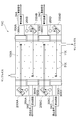
- FIG. 5 is a schematic cross-sectional view showing a gas concentration calculation apparatus 1XC that measures the gas concentration of each gas of the sample gas in which four kinds of gases are mixed.
- the reflection switching unit 200XA to 200XD are bulkier than the light receiving units 30XA to 30XD, the reflection switching unit 200XA is arranged on the left and the light receiving unit 30XA on the right at the uppermost stage in FIG.
- the light receiving unit 30XB is arranged on the left and the reflection switching unit 200XB is arranged on the right.
- the reflection switching unit 200XC is arranged on the left, and the light receiving unit 30XC is arranged on the right.
- each of the reflection switching units 200XA to 200XD has the same configuration as that of the reflection switching unit 100X of the first embodiment described above, and a gas to be measured is placed in the comparison gas chamber in each of the reflection switching units 200XA to 200XD. A saturated gas corresponding to is enclosed.
- Light emitted from the light sources 20XA to 20XD of the reflection switching units 200XA to 200XD is reflected by the reflecting mirrors or modulation mirrors provided in the reflection switching units 200XA to 200D, and enters the light receiving units 30XA to 30XD, respectively.
- band-pass filters 90XA to 90XD are arranged in the light receiving units 30XA to 30XD, respectively.
- Each of the bandpass filters 90XA to 90XD is an optical element that transmits light having a wavelength that is absorbed by the gas to be measured by each of the light receiving units 30XA to 30XD, and blocks light of other wavelengths. It is different every 30XD. Based on the energy value of the light received by each of the light receiving units 30XA to 30XD, the calculation circuits 3XA to 3XD calculate the concentration of the gas to be measured.
- the reflection switching units 200XA to 200XD and the light receiving units 30XA to 30XD are alternately arranged.
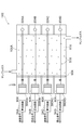
- the gas concentration calculation device 1XD shown in FIG. 20XD and reflection switching units 300XA to 300XD each including a light receiving unit that receives light emitted from the light sources 20XA to 20XD may be alternately arranged at both ends of the gas cell 10XA.
- FIG. 7 shows a gas concentration calculation apparatus 1XE according to another modification.
- FIG. 8 is a view of the reflection switching unit 300XA of the gas concentration calculation device 1XE as seen from the direction of the arrow L in FIG.
- the gas concentration calculation apparatus 1XE in the present modification has the reflection switching units 300XA to 300XD arranged on one side of the gas cell 10XA and the light sources 20XA to 20XD arranged on the other side.
- the reflection switching units 300XA to 300XD have the same configuration as the reflection switching unit 100XA according to the second embodiment described with reference to FIG.
- the light emitted from each of the light sources 20XA to 20XD is reflected by the reflection mirror and the modulation mirror in a direction orthogonal to the arrangement direction of the reflection units 300XA to 300XD and received by the light receiving unit. That is, the light radiated from the light sources 20XA to 20XD is reflected toward the back side of the sheet of FIG. 7 by the reflecting mirror and the modulation mirror, and is received by the light receiving unit 30X.
- a light source that emits light having a wavelength used for measurement of a plurality of gases may be used without preparing the light sources 20XA to 20XD for each gas. It can also be completed.
- gas concentration calculated by the gas concentration calculation devices 1X, 1XA to 1XE can be applied to various devices for calculating the gas concentration in addition to the control of the air conditioning.
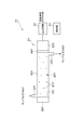
- FIG. 9 is a schematic cross-sectional view showing the gas concentration calculation apparatus 1Y.
- the gas concentration calculation device 1Y receives light from the light source 20Y and measures the energy value thereof, and a calculation circuit 3Y that calculates the gas concentration based on the measurement result of the gas concentration measurement module 2Y (patented) (Corresponding to “gas concentration calculating module” in claims) and a storage unit 4Y storing information necessary for the calculation circuit 3Y to calculate gas concentrations (corresponding to “storage means” in claims) And the concentration of the target gas is calculated.
- the gas concentration calculated by the calculation circuit 3Y is output to a control device (not shown) or the like, and is used for controlling an air conditioning system, for example.
- a control device not shown
- an example in which carbon dioxide in the sample gas 60Y introduced into the gas concentration measurement module 2Y is used as a concentration calculation target gas will be described.
- the gas concentration measurement module 2Y includes a gas cell 10Y, a light source 20Y, a modulation mirror 30Y (corresponding to “reflectance adjusting means” in claims), a bandpass filter 40Y, and a light receiving unit 50Y (in claims). "Corresponding to” light receiving means ").
- the gas cell 10Y forms an introduction space 11Y into which the sample gas 60Y is introduced.
- the gas cell 10Y is provided with a gas introduction part 12Y for introducing the sample gas 60Y into the introduction space 11Y on one end side of the gas cell 10Y, and the sample gas 60Y in the introduction space 11Y is externally connected to the other end side of the gas cell 10Y.
- a gas discharge part 13Y is provided for discharging the gas.
- the gas discharge unit 13Y may have a large number of holes in the inner wall (for example, the bottom) of the gas cell.
- the light source 20Y is disposed in the gas cell 10Y and emits infrared rays.
- a light source 20Y that emits light including light having a wavelength range of 4.2 ⁇ m to 4.3 ⁇ m is used.
- FIG. 9 shows an example in which the light source 20Y is arranged at the center bottom in the gas cell 10Y.
- the present invention is not limited to this, and the light source 20Y is arranged at the center top or center in the gas cell 10Y. Alternatively, it may be arranged somewhat deviated toward the modulation mirror 30Y side or the light receiving unit 50Y side. Infrared light from the light source 20Y is absorbed and attenuated by the carbon dioxide molecules 61Y in the sample gas 60Y.
- the modulation mirror 30Y is disposed at one end of the gas cell 10Y and electrically adjusts the reflectance with respect to the light emitted from the light source 20Y.
- a liquid crystal optical element or an electro-optical device (EO device) is employed as the modulation mirror 30Y.
- EO device electro-optical device
- other methods for controlling the reflectance with a dielectric, a metal mesh, or the like may be used.
- the band pass filter 40Y is disposed on the optical path between the light source 20Y and the light receiving unit 50Y, and allows only light of a predetermined wavelength to pass therethrough.
- a band pass filter 40Y is used that is disposed at the end of the gas cell 10Y on the light receiving unit 50Y side and transmits only light in the wavelength range of 4.2 ⁇ m to 4.3 ⁇ m.
- the light receiving unit 50Y is a light receiving element that is disposed at the other end of the gas cell 10Y and receives both the direct light directly emitted from the light source 20Y and the reflected light emitted from the light source 20Y and reflected by the modulation mirror 30Y. That is, one light receiving unit 50Y receives both direct light and reflected light. In other words, one light receiving unit 50Y receives light (direct light and the sum of direct light and reflected light, etc., as described later) when the reflectance is electrically adjusted by the modulation mirror 30Y. Therefore, as compared with the case of using a plurality of light receiving means for receiving a plurality of types of light, there is no adverse effect due to individual differences of the light receiving means.
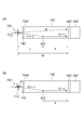
- FIG. 10 is a diagram for explaining a mechanism for generating a difference in the optical path length and the light reception energy value in the fourth embodiment.
- the change in the optical path length and the light reception energy value of the light starting from the light source 20Y disposed at the center of the gas cell 10Y and reaching the light receiving unit 50Y is performed by changing the reflectance of the modulation mirror 30Y.
- the reflectance is adjusted by the modulation mirror 30Y being totally reflected (modulation mirror 30Y is ON) or totally transmitted (modulation mirror 30Y is OFF).
- FIG. 10A shows a state in which the modulation mirror 30Y is in an ON state and all the light that has arrived from the light source 20Y is reflected.
- the direct light that is emitted from the light source 20Y and directly reaches the light receiving unit 50Y is indicated as I1 ( ⁇ ), and the length of the optical path through which the direct light passes is approximately L.
- the reflected light is displayed as I1 ( ⁇ ) (light emitted from the light source 20Y and reaching the modulation mirror 30Y) and I2 (light reflected by the modulation mirror 30Y and reaches the light receiving unit 50Y).
- the length of the optical path that passes is approximately 3L (L + 2L).
- FIG. 10B shows a state in which the modulation mirror 30Y is in an OFF state and the light reaching from the light source 20Y is transmitted without being reflected at all. In this case, only the direct light reaches the light receiving unit 50Y via a substantially L optical path, and the light reception energy value is measured.
- ON / OFF of the modulation mirror 30Y is shown depending on the presence or absence of hatching.
- FIG. 10B describes that light that does not reflect is transmitted, the present invention is not limited to this, and may be absorbed.
- the optical path length and the light reception energy value are electrically changed by the modulation mirror 30Y. For this reason, it is compact and the movable part can be eliminated, and there is no adverse effect such as displacement due to vibration and additional noise, and the accuracy is improved. Furthermore, the modulation speed can be greatly increased compared to the mechanical type.
- the storage unit 4Y includes a database indicating a correlation between the ratio of the light reception energy value of the light receiving unit 50Y and the concentration of carbon dioxide as the target gas when the reflectance is electrically adjusted by the modulation mirror 30Y. Alternatively, an approximate expression is stored in advance.
- FIG. 11 is a diagram for explaining storage information in the storage unit 4Y.
- FIG. 11 is basically the same diagram as FIG. 9 and FIG. 10, but only the elements necessary for the following explanation are left, and the optical path length is schematically indicated by L or 2L.
- the following equations (1) to (3) are established.
- I I1 ( ⁇ ) + I1 ( ⁇ ) (1)
- I1 ( ⁇ ) / I x (2)
- I1 ( ⁇ ) / I 1 ⁇ x (3)
- I is a total energy value of infrared rays emitted from the light source 20Y
- I1 ( ⁇ ) is direct light
- is an energy value of infrared rays emitted from the light source 20Y in the right direction in FIG. ( ⁇ ) is the energy value of infrared rays radiated leftward from the light source 20Y in FIG. 11
- x is the distribution ratio of I1 ( ⁇ ) and I1 ( ⁇ ).
- I2 is the reflected light, which is the energy value of the infrared light emitted from the light source 20Y in the left direction and reflected by the modulation mirror 30Y
- Ron is the reflection in the ON state of the modulation mirror 30Y.
- Ion is the total energy of infrared rays that reach the light receiving unit 50Y when the modulation mirror 30Y is ON, and is the total energy value of direct light and reflected light.
- the ratio between the energy value Ion of the light received by the light receiving unit 50Y when the modulation mirror 30Y is ON and the energy value Ioff of the light received by the light receiving unit 50Y when the modulation mirror 30Y is OFF (the “reflection” in the claims)
- the ratio of the light receiving energy value of the light receiving means in the case where the reflectance is electrically adjusted by the rate adjusting means is equivalent to the following.
- Ion / Ioff [xIexp ( ⁇ KCL) + (((1 ⁇ x) Iexp ( ⁇ KCL)) Ron) exp ( ⁇ 2KCL)] / [xIexp ( ⁇ KCL) + (((1 ⁇ x) Iexp ( ⁇ KCL)) Roff) exp (-2KCL)] (12)
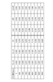
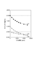
- FIG. 12 shows an example of the database created in this way. The concentration of carbon dioxide corresponding to each value of Ion / I, Ioff / I, and Ion / Ioff is shown in the database of FIG.
- a graph as shown in FIG. 13 may be obtained using the database of FIG.
- the graph shown in FIG. 13 shows the correlation between the concentration of carbon dioxide and the ratio Ion / Ioff.
- G1 is a graph showing the correlation between the concentration of carbon dioxide and the ratio Ion / Ioff
- G2 is a graph showing the correlation between the concentration of carbon dioxide and the ratio Ion / I
- G3 is carbon dioxide. It is a graph which shows the correlation with the density
- the storage unit 4Y stores information indicating such a database or graph.
- Ion / I the ratio of each energy value to the energy value I emitted from the light source, Ion / I is 1.
- I1 ( ⁇ ) / I, I1 ( ⁇ ) / I and I2 / I are shown to be 0.5 so that Ioff / I becomes 0.5. Since the energy I radiated from can not be measured, the value obtained as the measured value among the values shown in the database and the graph is only the ratio Ion / Ioff of the energy value.
- the correlation between the concentration of carbon dioxide and Ion / Ioff can be found based on the approximate expression f of Expression (14), the database of FIG. 12, or the graph of FIG. 13, so if Ion / Ioff is measured, The concentration of carbon dioxide can be calculated.
- the calculation circuit 3Y calculates the concentration of carbon dioxide from the energy value of the light received by the light receiving unit 50Y.
- the calculation circuit 3Y further calculates the approximate expression f described above based on the ratio (Ion / Ioff) of the light reception energy value of the light receiving unit 50Y when the reflectance is electrically adjusted by the modulation mirror 30Y.
- the calculation circuit calculates the concentration of carbon dioxide corresponding to the ratio, and includes a CPU and the like.
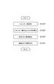
- FIG. 14 is a flowchart showing the flow of the carbon dioxide concentration calculation process.
- step S101Y the calculation circuit 3Y calculates the energy value Ion of the light received by the light receiving unit 50Y when the modulation mirror 30Y is ON, and the energy value Ioff of the light received by the light receiving unit 50Y when the modulation mirror 30Y is OFF. get.
- step S102Y the calculation circuit 3Y calculates a ratio (Ion / Ioff) between the acquired energy value Ion and the energy value Ioff.
- step S103Y the calculation circuit 3Y calculates the concentration of carbon dioxide from the ratio (Ion / Ioff) calculated in step S103Y, using the approximate expression f stored in the storage unit 4Y. By calculating the concentration using the approximate expression f, the calculation process can be easily performed.
- step S104Y the calculation circuit 3Y outputs a signal indicating the calculated concentration of carbon dioxide to a control device (not shown).
- the signal indicating the concentration of carbon dioxide is used, for example, for control of air conditioning in the control device.
- step S104Y the density value corresponding to the ratio (Ion / Ioff) calculated in step S102Y is read from the graph of FIG. 13, and the density value is output as the output value in step S104Y. May be.
- action and effect of the gas concentration calculation apparatus 1Y concerning 4th Embodiment are demonstrated.
- the gas concentration calculation apparatus 1Y of the fourth embodiment since the light receiving unit 50Y receives both direct light and reflected light, the direct light and the reflected light are received by different light receiving units 50Y, or a modulation mirror Problems due to individual differences in the light receiving unit 50Y when the light in each of the cases where the reflectance is electrically adjusted by 30Y are separately received by different light receiving units 50Y are prevented.
- the means for generating the change in the optical path length and the difference in the light receiving energy value in the light received by the light receiving unit 50Y is the modulation mirror 30Y, and the operation of the modulation mirror 30Y is based on the reflectivity.
- electrical control Accordingly, there is no vibration in order to generate a change in the optical path length or a difference in the received light energy value, and there is no position shift or additional noise due to the vibration. Can be prevented.
- the reflectance can be switched at high speed by the modulation mirror 30Y electrically controlling the reflectance. Therefore, it is as if there is no time lag in the light measurement timing received by the light receiving unit 50Y, or even if it is very short, pseudo-simultaneous measurement is possible.
- an electro-optical device EO device
- a liquid crystal optical element is suitable as the modulation mirror 30Y that brings about such an effect.
- the wavelength band of the received light can be made the same wavelength band by the band pass filter, and it is possible to prevent the light detection accuracy from being lowered due to the reception of light of different wavelength bands.
- the concentration of the target gas can be calculated with high accuracy based on a database or approximate expression prepared in advance.
- Modification, part 1 For example, in the fourth embodiment, the case where the concentration of carbon dioxide is calculated by the gas concentration calculation device 1Y has been described. However, the concentration of other gases can be calculated by changing the wavelength of light used for measurement. Needless to say. Further, the type of light source and the shape of the gas cell can be appropriately optimized according to the type of gas whose concentration is to be measured, the measurement range, and the measurement accuracy.
- Modification, part 2 15 and 16 show a modification for detecting the gas concentration of the sample gas 60Y in which a plurality of types of gases are mixed as a batch process.
- a plurality of light receiving means are used.
- concentration measurement for a plurality of types of gases can be realized as a batch process. That is, as shown in FIGS.
- the gas concentration measurement module 2Y including a plurality of light receiving units 50YA, 50YB, 50YC, and 50YD having different target gases and a plurality corresponding to the plurality of light receiving units 50YA, 50YB, 50YC, and 50YD.
- Gas concentration calculation modules (calculation circuits 3YA, 3YB, 3YC, 3YD and storage units 4YA, 4YB, 4YC, 4YD), thereby simultaneously detecting a plurality of gas concentrations in the sample gas 60Y in which a plurality of types of gases are mixed. be able to.
- 15 and 16 illustrate an apparatus for measuring the gas concentration of each gas of the sample gas 60Y in which four kinds of gases are mixed.
- a light source that emits light having a wavelength used for measurement is disposed inside the gas cell 10Y. If the wavelength range of the emitted light is wide and includes a wavelength range that can be used for absorption of each gas, as shown in FIG. 15, one light source 20Y can be used. Further, as shown in FIG. 16, different types of light sources 20YA, 20YB, 20YC, and 20YD that respectively emit light in the wavelength ranges detected by the light receiving units 50YA, 50YB, 50YC, and 50YD are received by the light receiving units 50YA, 50YB, 50YC, It may be provided every 50 YD.
- the modulation mirror when the wavelength range in which the reflectance can be controlled is narrow, as shown in FIG. 16, four modulation mirrors 30YA, 30YB, 30YC, and 30YD are provided for each wavelength that can be used for absorption of each gas. Each may be used to perform ON-OFF control.
- bandpass filters 40YA, 40YB, 40YC, and 40YD respectively disposed in the light receiving means 50YA, 50YB, 50YC, and 50YD are gases to be measured by the light receiving means 50YA, 50YB, 50YC, and 50YD.
- the sample gas 60Y is supplied to the gas cell 10Y, and measurement is performed.
- the gas concentration calculation method calculated for each of the light receiving means 50YA, 50YB, 50YC, and 50YD is the same as the above-described algorithm.
- the gas cell 10Y is divided into the respective light receiving means 50YA, 50YB, 50YC, and 50YD.
- the present invention is not limited to this, and as shown in FIG. 15, all the light receiving means 50YA. , 50YB, 50YC, 50YD may be one gas cell 10Y.
- the fourth embodiment exemplifies a case where the modulation mirror 30Y is turned on / off with respect to “when the reflectance is electrically adjusted by the reflectance adjusting means” in the claims.
- the present invention is not limited to this, and in the case where the reflectance is varied while the modulation mirror 30Y is maintained in the ON state, “the reflectance is electrically adjusted by the reflectance adjusting means” in the claims. It may be an example of “case”.
- the gas concentration calculated by the gas concentration calculation device 1Y can be applied to various devices for calculating the gas concentration in addition to the control of the air conditioning.
- FIG. 17 is a schematic cross-sectional view showing the gas concentration calculation device 1Z.
- the gas concentration calculation device 1Z receives light from the light source 20Z and measures the energy value thereof, and a calculation circuit 3Z that calculates the gas concentration based on the measurement result of the gas concentration measurement module 2Z (patented) (Corresponding to “gas concentration calculation module” in claims) and a storage unit 4Z storing information necessary for the calculation circuit 3Z to calculate gas concentrations (corresponding to “storage means” in claims) And the concentration of the target gas is calculated.
- the gas concentration calculated by the calculation circuit 3Z is output to a control device (not shown) or the like, and is used for control of an air conditioning system, for example.
- a control device not shown
- carbon dioxide in the sample gas 60Z introduced into the gas concentration measurement module 2Z is used as a concentration calculation target gas will be described.
- the gas concentration measurement module 2Z includes a gas cell 10Z, a light source 20Z, a rotary mirror 30Z (corresponding to “rotation mechanism” in claims), a band-pass filter 40Z, and a light receiving unit 50Z (“light reception” in claims). Equivalent to “means”).
- the gas cell 10Z forms an introduction space 11Z into which the sample gas 60Z is introduced.
- a gas introduction part 12Z for introducing the sample gas 60Z into the introduction space 11Z is provided on one end side of the gas cell 10Z, and the sample gas 60Z in the introduction space 11Z is externally connected to the other end side of the gas cell 10Z.
- a gas discharge part 13Z is provided for discharging the gas.
- the gas discharge part 13Z is good also as what has many holes provided in the inner wall (for example, bottom part) of a gas cell.
- the light source 20Z is disposed in the gas cell 10Z and emits infrared rays.
- a light source that emits light including light in the wavelength range of 4.2 ⁇ m to 4.3 ⁇ m is used as the light source 20Z.
- FIG. 17 shows an example in which the light source 20Z is arranged at the center bottom in the gas cell 10Z.
- the present invention is not limited to this, and the light source 20Z is arranged at the upper center or the center in the gas cell 10Z. Alternatively, it may be arranged somewhat deviated toward the rotary mirror 30Z side or the light receiving unit 50Z side. Infrared light from the light source 20Z is absorbed and attenuated by the carbon dioxide molecules 61Z in the sample gas 60Z.
- the rotary mirror 30Z is disposed on the one end 10aZ side of the gas cell 10Z, and reflects or transmits light emitted from the light source 20Z by rotation.
- the rotating mirror 30Z reflects or transmits light by rotating or moving in a direction different from the direction of the optical path from the light source 20Z to the light receiving unit 50Z.
- the direction of the optical path from the light source 20Z to the light receiving unit 50Z is the X direction
- the rotation of the rotary mirror 30Z is performed along the YZ plane. That is, the rotary mirror 30Z rotates on the YZ plane perpendicular to the X direction that is the direction of the optical path.
- the rotation of the rotary mirror 30Z on the YZ plane is indicated by an arrow.
- the direction of the optical path and the rotation axis of the rotary mirror 30Z are the same X direction, but the end 30aZ of the rotary mirror 30Z rotates while drawing a circle on the YZ plane.
- the rotary mirror 30Z does not move along the X direction that is the direction of the optical path.
- the rotary mirror 30Z includes a reflecting plate 31Z and a hole 32Z, and the rotation direction, the rotation speed, and the like are controlled by the rotation drive mechanism 33Z.
- the hole 32Z is a space surrounded by the frame 32aZ.
- a window portion 14Z made of a material having high transparency to infrared rays is provided on the one end 10aZ side of the gas cell 10Z.
- the band pass filter 40Z is disposed on the optical path between the light source 20Z and the light receiving unit 50Z, and allows only light having a predetermined wavelength to pass therethrough.
- a band pass filter 40Z is used that is disposed at the end of the gas cell 10Z on the light receiving unit 50Z side and transmits only light in the wavelength range of 4.2 ⁇ m to 4.3 ⁇ m.
- the light receiving unit 50Z is a light receiving element that is disposed at the other end of the gas cell 10Z and receives both direct light directly emitted from the light source 20Z and reflected light emitted from the light source 20Z and reflected by the rotary mirror 30Z. That is, one light receiving unit 50Z receives both direct light and reflected light. In other words, the light receiving unit 50Z receives the light (direct light and the total of the direct light and the reflected light as described later) when the light is reflected or transmitted by the rotary mirror 30Z. Therefore, as compared with the case of using a plurality of light receiving means for receiving a plurality of types of light, there is no adverse effect due to individual differences of the light receiving means.
- FIG. 18 is a diagram for explaining a mechanism for generating a difference in the optical path length and the light reception energy value in the fifth embodiment.
- the optical path length and the light reception energy value of light starting from the light source 20Z disposed at the center bottom of the gas cell 10Z and reaching the light receiving unit 50Z are changed by the rotation of the rotary mirror 30Z.
- the reflectance is adjusted by total reflection or total transmission of the rotary mirror 30Z.
- FIG. 18A shows a state in which the reflecting plate 31Z is positioned on the one end 10aZ side of the gas cell 10Z so as to face the light source 20Z by the rotation of the rotary mirror 30Z, and all the light reaching from the light source 20Z is reflected into the gas cell 10Z.
- direct light that is emitted from the light source 20Z and directly reaches the light receiving unit 50Z is indicated as I1 ( ⁇ ), and the length of the optical path through which the direct light passes is approximately L.
- the reflected light is indicated as I1 ( ⁇ ) (light emitted from the light source 20Z and reaching the reflecting plate 31Z) and I2 (light reflected by the reflecting plate 31Z and reaching the light receiving unit 50Z).
- the length of the optical path that passes is approximately 3L (L + 2L).
- both the direct light and the reflected light reach the light receiving unit 50Z via the L and 3L optical paths, respectively, and the light receiving energy value is measured.
- FIG. 18B shows a state in which the hole 32Z is positioned on the one end 10aZ side of the gas cell 10Z so as to face the light source 20Z by the rotation of the rotary mirror 30Z, and does not reflect the light reaching from the light source 20Z.
- the state of transmission is shown. In this case, only the direct light reaches the light receiving unit 50Z via the optical path of approximately L, and the light reception energy value is measured.
- FIG. 18B it is described that light that is not reflected is transmitted through the hole 32Z.
- the present invention is not limited to this, and may be absorbed. In this case, an absorber (not shown) can be provided instead of the hole 32Z.
- the optical path length and the light reception energy value are changed by rotating the rotating mirror 30Z in a direction different from the optical path length direction. For this reason, it is not necessary for the rotary mirror 30Z to move along the optical path length direction in order to generate a change in the optical path length or a difference in the received light energy value. That is, although the rotary mirror 30Z rotates, it does not move in the optical path length direction, and therefore there is no change in the absolute distance between the rotary mirror 30Z and the light receiving unit 50Z. Therefore, since the optical path length is stabilized, highly accurate measurement can be realized without temporarily stopping the rotary mirror 30Z. As a result, it is possible to prevent a significant time lag from occurring in the light measurement timing due to the temporary movement of the rotary mirror 30Z.
- the storage unit 4Z has a database or an approximation indicating the correlation between the ratio of the light reception energy value of the light receiving unit 50Z and the concentration of carbon dioxide as the target gas when light is reflected or transmitted by the rotary mirror 30Z. Expressions are stored in advance.
- FIG. 19 is a diagram for explaining storage information in the storage unit 4Z.
- FIG. 19 is basically the same as FIG. 17 and FIG. 18, but only the elements necessary for the following explanation are left, and the optical path length is schematically indicated by L or 2L.
- I I1 ( ⁇ ) + I1 ( ⁇ ) (1)
- I1 ( ⁇ ) / I x (2)
- I1 ( ⁇ ) / I 1 ⁇ x (3)
- I is a total energy value of infrared rays emitted from the light source 20Z
- I1 ( ⁇ ) is direct light
- is an energy value of infrared rays emitted from the light source 20Z in the right direction in FIG. ( ⁇ ) is the energy value of infrared rays radiated leftward from the light source 20Z in FIG. 19
- x is the distribution ratio of I1 ( ⁇ ) and I1 ( ⁇ ).
- K is an absorption coefficient
- C the concentration of carbon dioxide in the sample gas 60Z introduced into the gas cell 10Z
- L is the distance from the light source 20Z to the light receiving unit 50Z
- 2L is the rotating mirror 30Z.
- Roff is the reflectance of the rotary mirror 30Z (hole 32Z) in this state, and basically Roff is 0 because it is the hole 32Z.
- Ioff is the total energy of infrared rays that reach the light receiving unit 50Z in this state, and there is no reflected light due to the presence of the hole 32Z, and it is an energy value of only direct light.
- FIG. 20 shows an example of the database created in this way.
- the database of FIG. 20 shows the concentration of carbon dioxide corresponding to each value of Ion / I, Ioff / I, and Ion / Ioff.
- a graph as shown in FIG. 21 may be obtained using the database of FIG.
- the graph shown in FIG. 21 shows the correlation between the concentration of carbon dioxide and the ratio Ion / Ioff, and the like.
- G1 is a graph showing the correlation between the concentration of carbon dioxide and the ratio Ion / Ioff
- G2 is a graph showing the correlation between the concentration of carbon dioxide and the ratio Ion / I
- G3 is carbon dioxide. It is a graph which shows the correlation with the density
- the storage unit 4Z stores information indicating such a database or graph.
- the energy value I radiated from the light source of each energy value is set so that Ion / Ioff becomes 2. So that Ioff / I is 0.5 so that Ion / I is 1, and I1 ( ⁇ ) / I, I1 ( ⁇ ) / I and I2 / I are 0.5.
- the value obtained as the measurement value among the values shown in the database and the graph is only the energy value ratio Ion / Ioff.
- the correlation between the concentration of carbon dioxide and Ion / Ioff can be found based on the approximate expression f of Expression (14), the database of FIG. 20, or the graph of FIG. 21, so that if Ion / Ioff is measured, The concentration of carbon dioxide can be calculated.
- FIG. 22 is a flowchart showing a flow of carbon dioxide concentration calculation processing.
- step S101Z the calculation circuit 3Z calculates the energy value Ion of the light received by the light receiving unit 50Z when the reflecting plate 31Z faces the light source 20Z, and the light received by the light receiving unit 50Z when the hole 32Z faces the light source 20Z. An energy value Ioff is acquired.
- step S102Z the calculation circuit 3Z calculates a ratio (Ion / Ioff) between the acquired energy value Ion and the energy value Ioff.
- step S103Z the calculation circuit 3Z calculates the concentration of carbon dioxide from the ratio (Ion / Ioff) calculated in step S103Z, using the approximate expression f stored in the storage unit 4Z. By calculating the concentration using the approximate expression f, the calculation process can be easily performed.
- step S104Z the calculation circuit 3Z outputs a signal indicating the calculated concentration of carbon dioxide to a control device (not shown).
- the signal indicating the concentration of carbon dioxide is used, for example, for control of air conditioning in the control device.
- the table shown in FIG. 20 when the table shown in FIG. 20 is used, the table is searched using the ratio (Ion / Ioff) calculated in step S102Z, and the corresponding density value is obtained. You may output as an output value in step S104Z.
- the density value corresponding to the ratio (Ion / Ioff) calculated in step S102Z is read from the graph in FIG. 21, and the density value is output as the output value in step S104Z. May be.
- the rotating mirror 30Z is a means for generating a change in optical path length and a difference in received light energy value in the light received by the light receiving unit 50Z.
- the rotating mirror 30Z is connected to the light receiving unit from the light source 20Z. By rotating in a direction different from the direction of the optical path up to 50Z, light is reflected or transmitted.
- “rotation in a direction different from the direction of the optical path” can be achieved, for example, by setting the rotation axis of the rotary mirror 30Z in the same direction as the optical path. That is, it is not necessary for the rotating mirror 30Z to move along the direction of the optical path in order to generate a change in the optical path length or a difference in the received light energy value.
- the fifth embodiment it is possible to prevent problems due to individual differences in the light receiving unit 50Z and problems due to movement of an element for changing the optical path length in the same direction as the direction of the optical path.
- a simple configuration is possible with the rotary mirror 30Z composed of the reflecting plate 31Z and the hole 32Z, and by rotating the rotary mirror 30Z in a direction substantially perpendicular to the direction of the optical path, Can clearly switch between reflection and transmission.
- the wavelength band of the received light can be made the same wavelength band by the band pass filter, and it is possible to prevent the light detection accuracy from being lowered due to the reception of light of different wavelength bands.
- the concentration of the target gas can be calculated with high accuracy based on a database or approximate expression prepared in advance.
- FIG. 23A is a schematic cross-sectional view showing the gas concentration calculation device 1ZA.
- the MEMS actuator 70Z is disposed on the one end 10aZ side of the gas cell 10Z, and reflects or transmits light emitted from the light source 20Z by rotating the mirror 71Z by a certain angle.
- “reflection” means that the light from the light source 20Z is reflected into the gas cell 10Z
- “transmission” means whether the light from the light source 20Z is transmitted outside the gas cell 10Z without being reflected into the gas cell 10Z. Or reflecting outside the gas cell 10Z.
- transmission will be described as meaning that light is reflected outside the gas cell 10Z.
- the rotation of the MEMS actuator 70Z means the rotation of the mirror 71Z by the MEMS actuator 70Z.
- the MEMS actuator 70Z reflects or transmits light when the mirror 71Z rotates or moves in a direction different from the direction of the optical path from the light source 20Z to the light receiving unit 50Z.
- the direction of the optical path from the light source 20Z to the light receiving unit 50Z is the X direction
- the mirror 71Z of the MEMS actuator 70Z rotates about an axis K different from the X axis by a predetermined angle ⁇ . It rotates by a certain angle as an axis.
- the rotation of the mirror 71Z is indicated by an arrow.
- the MEMS actuator 70Z does not move along the X direction that is the direction of the optical path.
- the rotational direction and rotational speed of the MEMS actuator 70Z are controlled by a rotational drive mechanism (not shown).
- a window portion 14Z made of a material having high transparency to infrared rays is provided on the one end 10aZ side of the gas cell 10Z.
- the MEMS actuator 70Z includes actuator elements 73Z that move in the X direction at both ends of the mirror 71Z, and when one moves in the + X direction, the other moves in the ⁇ X direction.
- the position of the center of the mirror 71Z in the X direction does not move, and the mirror 71Z is rotated by a certain angle.
- the distance in the X direction between the light source 20Z and the mirror 71Z, and the mirror 71Z and the light receiving unit 50Z. can be kept constant without changing.
- the MEMS actuator 70Z is smaller in size than the rotating mirror 30Z of the fifth embodiment, the actuator 71Z is not provided at both ends of the mirror 71Z, but is provided with an actuator element 73Z only at one end as shown in FIG. Even if the ends are fixed, the distance in the X direction between the light source 20Z and the mirror 71Z, and between the mirror 71Z and the light receiving unit 50Z does not change and can be regarded as constant.
- FIG. 24 is a diagram for explaining a mechanism for generating a difference in the optical path length and the light reception energy value in the sixth embodiment.
- the optical path length and the light reception energy value of the light starting from the light source 20Z and reaching the light receiving unit 50Z are changed by the rotation of the MEMS actuator 70Z.
- the reflectance is adjusted by reflecting all the light input by the MEMS actuator 70Z into or out of the gas cell 10Z.
- FIG. 24A shows a state in which all the light that has reached from the light source 20Z is reflected into the gas cell 10Z by the rotation of the MEMS actuator 70Z mirror 71Z.
- direct light which is light emitted from the light source 20Z and directly reaches the light receiving unit 50Z
- I1 ( ⁇ ) direct light
- I2 light reflected by the mirror 71Z of the MEMS actuator 70Z and reached the light receiving unit 50Z.
- the length of the optical path through which the reflected light passes is approximately 3L (L + 2L).
- both the direct light and the reflected light reach the light receiving unit 50Z via the L and 3L optical paths, respectively, and the light reception energy value is Measured.
- FIG. 24B shows a state in which all the light reaching from the light source 20Z is reflected outside the gas cell 10Z by the rotation of the mirror 71Z of the MEMS actuator 70Z. In this case, only the direct light reaches the light receiving unit 50Z via the optical path of approximately L, and the light reception energy value is measured.
- the optical path length and the light reception energy value are changed by rotation in a direction different from the optical path length direction of the mirror 71Z of the MEMS actuator 70Z. For this reason, it is not necessary for the mirror 71Z to move along the optical path length direction in order to generate a change in the optical path length or a difference in the received light energy value. That is, although the mirror 71Z rotates, it does not move in the optical path length direction, and therefore there is no change in the absolute distance between the mirror 71Z and the light receiving unit 50Z. Therefore, since the optical path length is stable, high-precision measurement can be realized without temporarily stopping the mirror 71Z. As a result, it is possible to prevent a significant time shift from occurring in the light measurement timing due to the temporary movement stop of the mirror 71Z.
- the MEMS actuator 70Z by using the MEMS actuator 70Z, high-speed rotation is possible while suppressing vibration during rotation. Therefore, it is possible to prevent a decrease in light detection accuracy due to vibration.
- the high-speed rotation of the mirror 71Z of the MEMS actuator 70Z allows the light to be reflected and transmitted (reflected outside the gas cell 10Z) at a high speed, so that there is no time shift in the light measurement timing of the light receiving unit 50Z. Or even if it exists, it is very short, and quasi-simultaneous measurement becomes possible.
- the other one side of the present invention is not limited to the above-mentioned 5th and 6th embodiments.
- the concentration of carbon dioxide is calculated by the gas concentration calculation devices 1Z and 1ZA.
- the concentration of can be calculated.
- the type of light source and the shape of the gas cell can be appropriately optimized according to the type of gas whose concentration is to be measured, the measurement range, and the measurement accuracy.
- FIG. 25 shows a modification for detecting the gas concentration of the sample gas 60Z in which plural kinds of gases are mixed as a batch process.
- the gas concentration measurement module of the present application a plurality of light receiving means are used. By providing a gas concentration calculation module for each light receiving means, concentration measurement for a plurality of types of gases can be realized as a batch process. That is, as shown in FIG.
- the gas concentration measurement module 2Z having a plurality of light receiving means 50ZA, 50ZB, 50ZC, and 50ZD having different target gases and a plurality of gas concentrations corresponding to the plurality of light receiving means 50ZA, 50ZB, 50ZC, and 50ZD.
- calculation modules calculation circuits 3ZA, 3ZB, 3ZC, 3ZD and storage units 4ZA, 4ZB, 4ZC, 4ZD
- FIG. 25 illustrates an apparatus for measuring the gas concentration of each gas of the sample gas 60Z in which four kinds of gases are mixed.
- a light source that emits light having a wavelength used for measurement is disposed inside the gas cell 10Z. If the wavelength range of the emitted light is wide and includes a wavelength range that can be used for absorption of each gas, one light source 20Z can be used as shown in FIG. Although not shown, different types of light sources 20ZA, 20ZB, 20ZC, and 20ZD that emit light in the wavelength ranges detected by the light receiving units 50ZA, 50ZB, 50ZC, and 50ZD are provided for the light receiving units 50ZA, 50ZB, 50ZC, and 50ZD, respectively. May be provided.
- band pass filters 40ZA, 40ZB, 40ZC, and 40ZD respectively disposed in the light receiving means 50ZA, 50ZB, 50ZC, and 50ZD absorb the gas to be measured by the light receiving means 50ZA, 50ZB, 50ZC, and 50ZD.
- An optical element that transmits light of a wavelength and blocks light of other wavelengths, and different bandpass filters 40ZA, 40ZB, 40ZC, and 40ZD are arranged for each of the light receiving means 50ZA, 50ZB, 50ZC, and 50ZD. Further, the sample gas 60Z is supplied to the gas cell 10Z, and measurement is performed.
- FIG. 25 shows a plurality of sixth embodiments, but a plurality of fifth embodiments may be used. In that case, the rotation mechanism is shared between the gas concentration measurement modules arranged vertically, and when one is reflecting, the other may be transmitted.
- the present invention is not limited to this, and is reflected or reflected with a certain degree of reflectance or transmittance. You may comprise an apparatus so that it may permeate
- gas concentration calculated by the gas concentration calculation devices 1Z and 1ZA can be applied to various devices for calculating the gas concentration in addition to the control of the air conditioning.
- 1X, 1XA to 1XE ... gas concentration calculation device 2X, 2XA, 2XB ... gas concentration measurement module, 3X, 3XA to 3XD ... calculation circuit, 10X ... gas cell, 11X ... introduction space, 20X ... infrared light source, 20XA-20XD ... Light source, 30X ... light receiving unit, 40X ... saturated gas chamber, 41X ... saturated gas, 50X ... sample gas, 60X, 60XA ... reflecting mirror, 70X ... modulating mirror, 80X ... rotating mirror, 81X ... reflecting plate, 82X ... hole, 90X ... band pass filters, 100X, 100XA, 100XB, 200XA to 200XD, 300XA to 300XD ... reflection switching unit.
- One aspect of the present invention provides a gas concentration calculation device and a gas concentration measurement module that can prevent problems due to individual differences in light receiving elements and prevent problems due to unstable optical path length.
- Another aspect of the present invention is to prevent problems due to individual differences in light receiving means, and prevent a decrease in light detection accuracy due to vibration of elements for causing a change in optical path length and a difference in received light energy value.
- a gas concentration calculation device and a gas concentration measurement module capable of suppressing a decrease in light detection accuracy due to a shift in light measurement time.
- Still another aspect of the present invention is that an element for preventing a failure due to individual differences in light receiving means and causing a change in optical path length or a difference in received light energy value moves in the same direction as the direction of the optical path.
- a gas concentration calculation device and a gas concentration measurement module capable of preventing problems caused by the above.
Landscapes
- Physics & Mathematics (AREA)
- General Physics & Mathematics (AREA)
- Immunology (AREA)
- Biochemistry (AREA)
- Pathology (AREA)
- Health & Medical Sciences (AREA)
- Life Sciences & Earth Sciences (AREA)
- Chemical & Material Sciences (AREA)
- Analytical Chemistry (AREA)
- General Health & Medical Sciences (AREA)
- Spectroscopy & Molecular Physics (AREA)
- Optics & Photonics (AREA)
- Theoretical Computer Science (AREA)
- Mathematical Physics (AREA)
- Engineering & Computer Science (AREA)
- Investigating Or Analysing Materials By Optical Means (AREA)
Priority Applications (4)
| Application Number | Priority Date | Filing Date | Title |
|---|---|---|---|
| EP11744602.1A EP2538202A4 (de) | 2010-02-16 | 2011-02-14 | Vorrichtung zur berechnung einer gaskonzentration und modul zur messung einer gaskonzentration |
| KR1020127022557A KR101792891B1 (ko) | 2010-02-16 | 2011-02-14 | 가스 농도 산출 장치 및 가스 농도 계측 모듈 |
| CN201180009780.0A CN102762976B (zh) | 2010-02-16 | 2011-02-14 | 气体浓度计算装置及气体浓度测量模块 |
| US13/578,913 US9274048B2 (en) | 2010-02-16 | 2011-02-14 | Gas concentration calculation device and gas concentration measurement module |
Applications Claiming Priority (6)
| Application Number | Priority Date | Filing Date | Title |
|---|---|---|---|
| JP2010031560A JP5421148B2 (ja) | 2010-02-16 | 2010-02-16 | ガス濃度算出装置およびガス濃度計測モジュール |
| JP2010-031560 | 2010-02-16 | ||
| JP2010-031564 | 2010-02-16 | ||
| JP2010-031562 | 2010-02-16 | ||
| JP2010031562A JP2011169645A (ja) | 2010-02-16 | 2010-02-16 | ガス濃度算出装置及びガス濃度計測モジュール |
| JP2010031564A JP5325137B2 (ja) | 2010-02-16 | 2010-02-16 | ガス濃度算出装置およびガス濃度計測モジュール |
Publications (1)
| Publication Number | Publication Date |
|---|---|
| WO2011102316A1 true WO2011102316A1 (ja) | 2011-08-25 |
Family
ID=44482901
Family Applications (1)
| Application Number | Title | Priority Date | Filing Date |
|---|---|---|---|
| PCT/JP2011/053041 Ceased WO2011102316A1 (ja) | 2010-02-16 | 2011-02-14 | ガス濃度算出装置及びガス濃度計測モジュール |
Country Status (6)
| Country | Link |
|---|---|
| US (1) | US9274048B2 (de) |
| EP (1) | EP2538202A4 (de) |
| KR (1) | KR101792891B1 (de) |
| CN (2) | CN102762976B (de) |
| TW (1) | TWI512280B (de) |
| WO (1) | WO2011102316A1 (de) |
Families Citing this family (28)
| Publication number | Priority date | Publication date | Assignee | Title |
|---|---|---|---|---|
| HUE065359T2 (hu) | 2011-03-18 | 2024-05-28 | Alkermes Pharma Ireland Ltd | Szorbitán-észtereket tartalmazó gyógyászati készítmények |
| JP6416453B2 (ja) * | 2011-08-12 | 2018-10-31 | 株式会社堀場製作所 | ガス分析装置 |
| ES2765036T3 (es) | 2012-03-19 | 2020-06-05 | Alkermes Pharma Ireland Ltd | Composiciones farmacéuticas que comprenden esteres de ácidos grasos |
| ES2950418T3 (es) | 2012-03-19 | 2023-10-09 | Alkermes Pharma Ireland Ltd | Composiciones farmacéuticas que comprenden alcohol bencílico |
| JP6219918B2 (ja) | 2012-03-19 | 2017-10-25 | アルカームス ファーマ アイルランド リミテッド | グリセロールエステルを含む医薬組成物 |
| EP2897592B1 (de) | 2012-09-19 | 2020-02-19 | Alkermes Pharma Ireland Limited | Pharmazeutische zusammensetzungen mit verbesserter lagerstabilität |
| BR112016021535A8 (pt) | 2014-03-20 | 2021-07-20 | Alkermes Pharma Ireland Ltd | kit compreendendo formulações de aripiprazol tendo velocidades de injeção aumentadas útil para o tratamento de uma desordem do sistema nervoso central e uso |
| WO2017043263A1 (ja) * | 2015-09-09 | 2017-03-16 | 株式会社村田製作所 | ガス濃度検出装置 |
| CN105223149A (zh) * | 2015-11-13 | 2016-01-06 | 苏州谱道光电科技有限公司 | 测量系统及其光学元件 |
| KR101663003B1 (ko) | 2016-01-07 | 2016-10-06 | 주식회사본길 | 곡면 거울이 구비된 가스셀 및 이를 이용한 푸리에 변환 적외선 분광기 |
| US10585253B2 (en) * | 2016-05-03 | 2020-03-10 | Ut-Battelle, Llc | CTIR spectrometer for large area assessment of gas emissions |
| JP6912766B2 (ja) * | 2016-07-29 | 2021-08-04 | 国立大学法人徳島大学 | 濃度測定装置 |
| US11802700B2 (en) | 2017-04-06 | 2023-10-31 | Carrier Corporation | Moderate-to-low global warming potential value refrigerant leak detection |
| DE102017205974A1 (de) * | 2017-04-07 | 2018-10-11 | Robert Bosch Gmbh | Optische Sensorvorrichtung zum Messen einer Fluidkonzentration und Verwendung der optischen Sensorvorrichtung |
| KR102607020B1 (ko) * | 2017-09-19 | 2023-11-29 | 가부시키가이샤 호리바 에스텍 | 농도 제어 장치 및 재료 가스 공급 장치 |
| JP7154850B2 (ja) * | 2017-09-19 | 2022-10-18 | 株式会社堀場エステック | 濃度制御装置及び材料ガス供給装置 |
| EP3761983A1 (de) | 2018-03-05 | 2021-01-13 | Alkermes Pharma Ireland Limited | Dosierstrategie für aripiprazol |
| JP2019184523A (ja) * | 2018-04-16 | 2019-10-24 | 横河電機株式会社 | ガス分析装置 |
| CN110967297A (zh) * | 2018-09-29 | 2020-04-07 | 深圳市帝迈生物技术有限公司 | 光学检测系统及其校准方法 |
| CN111856745B (zh) * | 2019-04-30 | 2023-03-17 | 上海微电子装备(集团)股份有限公司 | 一种光照射装置 |
| US12228510B2 (en) * | 2019-05-28 | 2025-02-18 | Si-Ware Systems | Integrated device for fluid analysis |
| KR102631017B1 (ko) * | 2019-09-09 | 2024-01-31 | 한국전력공사 | 다종 가스 측정장치 및 측정방법 |
| CN110579474B (zh) * | 2019-09-24 | 2024-10-18 | 中国科学院力学研究所 | 一种同时观测晶体形貌及测量晶体周围浓度场的装置 |
| CN111610189B (zh) * | 2020-07-03 | 2021-08-31 | 福州大学 | 一种多组分气体浓度光学标定系统及方法 |
| KR102410126B1 (ko) * | 2020-11-03 | 2022-06-20 | 한국광기술원 | 비분산식 유해 가스 검출 장치 및 방법 |
| KR102434637B1 (ko) * | 2020-12-16 | 2022-08-19 | (재)한국나노기술원 | 접촉 압력 및 가스 농도 감지 장치 |
| FI4567404T3 (fi) * | 2023-12-08 | 2026-01-19 | Axetris Ag | Laite, järjestelmä ja menetelmä optista kaasunanalyysiä varten |
| US20260056120A1 (en) * | 2024-08-23 | 2026-02-26 | Schlumberger Technology Corporation | Measurement of multiple gas concentrations |
Citations (9)
| Publication number | Priority date | Publication date | Assignee | Title |
|---|---|---|---|---|
| JPS643527A (en) * | 1987-06-26 | 1989-01-09 | Shimadzu Corp | Double beam spectrophotometer |
| JPH05180760A (ja) | 1991-12-28 | 1993-07-23 | Horiba Ltd | 吸光分析計 |
| JPH08271417A (ja) * | 1995-03-29 | 1996-10-18 | Shimadzu Corp | オイル劣化度測定装置 |
| JP2002022656A (ja) * | 2000-07-04 | 2002-01-23 | Shimadzu Corp | 分光光度計 |
| JP2006023284A (ja) * | 2004-06-11 | 2006-01-26 | Shimadzu Corp | 紫外可視近赤外分光光度計用検出装置 |
| JP2007025143A (ja) * | 2005-07-14 | 2007-02-01 | Asahi Glass Co Ltd | 液晶光学素子および装置 |
| JP2007256790A (ja) * | 2006-03-24 | 2007-10-04 | Sumitomo Chemical Co Ltd | 酸素遮断膜、基板、パターン形成方法及びカラーフィルタ製造方法 |
| JP2007256242A (ja) | 2006-03-27 | 2007-10-04 | Riken Keiki Co Ltd | 赤外線式ガス検知器 |
| WO2007139022A1 (ja) * | 2006-05-26 | 2007-12-06 | Nalux Co., Ltd. | 赤外光源およびその製造方法 |
Family Cites Families (23)
| Publication number | Priority date | Publication date | Assignee | Title |
|---|---|---|---|---|
| US3793525A (en) | 1973-01-02 | 1974-02-19 | Philco Ford Corp | Dual cell non-dispersive gas analyzer |
| US3824104A (en) | 1973-04-05 | 1974-07-16 | Grace W & Co Washington Res Ce | Solder resistant photopolymer composition |
| US3813146A (en) * | 1973-05-04 | 1974-05-28 | Philco Ford Corp | Light beam alternator having a single rotating mirror |
| JPS5234510A (en) | 1975-09-10 | 1977-03-16 | Tai Nakashin | Material to be cast for impervious wall construction |
| JPS52122172A (en) | 1976-04-07 | 1977-10-14 | Matsushita Electric Ind Co Ltd | Gas analyser |
| JPS5398889A (en) | 1977-02-09 | 1978-08-29 | Yokogawa Hokushin Electric Corp | Infrared gas analyzer |
| JPS56116656A (en) | 1980-02-19 | 1981-09-12 | Nec Corp | Manufacturing of high-density wiring pattern |
| JPS61254835A (ja) | 1985-05-08 | 1986-11-12 | Horiba Ltd | 測定セル |
| JPH034458A (ja) | 1989-05-30 | 1991-01-10 | Yuasa Battery Co Ltd | 密閉形鉛蓄電池 |
| US5206511A (en) | 1990-10-18 | 1993-04-27 | Cascadia Technology Corporation | Calibrators for infrared-type gas analyzers |
| JP3004458B2 (ja) | 1992-04-13 | 2000-01-31 | 株式会社東芝 | 開水路用電磁流量計 |
| JPH08128956A (ja) | 1994-11-01 | 1996-05-21 | Hamamatsu Photonics Kk | ガス濃度測定装置 |
| IL121793A (en) | 1997-09-17 | 2008-06-05 | Lewis Coleman | Isotopic gas analyzer |
| JP4158314B2 (ja) | 2000-05-12 | 2008-10-01 | 株式会社島津製作所 | 同位体ガス測定装置 |
| CN1151363C (zh) * | 2000-12-29 | 2004-05-26 | 山西大学 | 用于气体检测的低频电压调制光谱的方法和装置 |
| JP2003329585A (ja) | 2002-05-09 | 2003-11-19 | Toyota Auto Body Co Ltd | オゾン濃度計 |
| US7190499B2 (en) * | 2004-01-05 | 2007-03-13 | E-Pin Optical Industry Co., Ltd. | Laser scanning unit |
| JP2005195801A (ja) | 2004-01-06 | 2005-07-21 | Shimadzu Corp | 赤外顕微鏡 |
| WO2006125470A1 (en) | 2005-05-24 | 2006-11-30 | Agilent Technologies, Inc. | Multi-path flow cell correction |
| WO2007141826A1 (ja) * | 2006-05-26 | 2007-12-13 | Nalux Co., Ltd. | 赤外光源 |
| JP5030629B2 (ja) | 2007-03-20 | 2012-09-19 | 大塚電子株式会社 | ガス濃度の定量分析方法及び装置 |
| CN100590418C (zh) | 2007-12-29 | 2010-02-17 | 北京航空航天大学 | 一种二氧化碳气体分析仪及其分析方法 |
| US20110095189A1 (en) * | 2009-10-26 | 2011-04-28 | Lall Ravinder P | Tactical chemical biological threat detection |
-
2011
- 2011-02-14 EP EP11744602.1A patent/EP2538202A4/de not_active Withdrawn
- 2011-02-14 CN CN201180009780.0A patent/CN102762976B/zh active Active
- 2011-02-14 WO PCT/JP2011/053041 patent/WO2011102316A1/ja not_active Ceased
- 2011-02-14 KR KR1020127022557A patent/KR101792891B1/ko active Active
- 2011-02-14 CN CN201410331121.4A patent/CN104111233B/zh active Active
- 2011-02-14 US US13/578,913 patent/US9274048B2/en active Active
- 2011-02-16 TW TW100105141A patent/TWI512280B/zh active
Patent Citations (9)
| Publication number | Priority date | Publication date | Assignee | Title |
|---|---|---|---|---|
| JPS643527A (en) * | 1987-06-26 | 1989-01-09 | Shimadzu Corp | Double beam spectrophotometer |
| JPH05180760A (ja) | 1991-12-28 | 1993-07-23 | Horiba Ltd | 吸光分析計 |
| JPH08271417A (ja) * | 1995-03-29 | 1996-10-18 | Shimadzu Corp | オイル劣化度測定装置 |
| JP2002022656A (ja) * | 2000-07-04 | 2002-01-23 | Shimadzu Corp | 分光光度計 |
| JP2006023284A (ja) * | 2004-06-11 | 2006-01-26 | Shimadzu Corp | 紫外可視近赤外分光光度計用検出装置 |
| JP2007025143A (ja) * | 2005-07-14 | 2007-02-01 | Asahi Glass Co Ltd | 液晶光学素子および装置 |
| JP2007256790A (ja) * | 2006-03-24 | 2007-10-04 | Sumitomo Chemical Co Ltd | 酸素遮断膜、基板、パターン形成方法及びカラーフィルタ製造方法 |
| JP2007256242A (ja) | 2006-03-27 | 2007-10-04 | Riken Keiki Co Ltd | 赤外線式ガス検知器 |
| WO2007139022A1 (ja) * | 2006-05-26 | 2007-12-06 | Nalux Co., Ltd. | 赤外光源およびその製造方法 |
Non-Patent Citations (1)
| Title |
|---|
| See also references of EP2538202A4 * |
Also Published As
| Publication number | Publication date |
|---|---|
| EP2538202A1 (de) | 2012-12-26 |
| CN102762976A (zh) | 2012-10-31 |
| CN102762976B (zh) | 2015-09-09 |
| US9274048B2 (en) | 2016-03-01 |
| CN104111233B (zh) | 2017-09-15 |
| US20130003046A1 (en) | 2013-01-03 |
| CN104111233A (zh) | 2014-10-22 |
| EP2538202A4 (de) | 2018-03-21 |
| TWI512280B (zh) | 2015-12-11 |
| TW201140027A (en) | 2011-11-16 |
| KR101792891B1 (ko) | 2017-11-20 |
| KR20130042465A (ko) | 2013-04-26 |
Similar Documents
| Publication | Publication Date | Title |
|---|---|---|
| WO2011102316A1 (ja) | ガス濃度算出装置及びガス濃度計測モジュール | |
| EP2216641B1 (de) | Mehrfachstrahl-Breitband-CRDS-Gasmessvorrichtung | |
| JP7094467B2 (ja) | 多重反射セル、ガス分析装置、及び多重反射セルの構成方法 | |
| RU2715368C1 (ru) | Измерительное устройство для определения различных газов и концентраций газов и способ определения различных газов и концентраций газов | |
| US9131877B2 (en) | Laser apparatus and photoacoustic apparatus | |
| CN106574869A (zh) | 具有可变光束功率和形状的光谱仪 | |
| US11460397B2 (en) | Gas measurement sensor | |
| JP6264741B2 (ja) | 分光分析装置 | |
| CN111855611B (zh) | 一种光程可调气体吸收池及气体检测装置 | |
| JP2011169633A (ja) | ガス濃度算出装置およびガス濃度計測モジュール | |
| JP5325137B2 (ja) | ガス濃度算出装置およびガス濃度計測モジュール | |
| JP2009014465A (ja) | 赤外ガス分析計 | |
| JP5421148B2 (ja) | ガス濃度算出装置およびガス濃度計測モジュール | |
| JP6283291B2 (ja) | ガス分析装置及びガスセル | |
| JP2011169645A (ja) | ガス濃度算出装置及びガス濃度計測モジュール | |
| JP2010249726A (ja) | ガス分析装置 | |
| JP2007040981A (ja) | ウエハ温度測定方法及びウエハ温度測定装置 | |
| JP6778671B2 (ja) | 多重反射セル及びガス分析装置 | |
| US12584792B2 (en) | Light measuring device and method of manufacturing light measuring device | |
| CN107036981B (zh) | 吸收光谱仪 | |
| JP2024032657A (ja) | 光測定装置及び光測定装置の製造方法 | |
| CN120992508A (zh) | 动态重构与混合光路自校准光声光谱气体检测装置与方法 | |
| Neumann et al. | Multi-Colour and Tunable-Colour Pyroelectric Detectors | |
| CN110346300A (zh) | 光声光谱检测系统及方法 | |
| PL211615B1 (pl) | Urządzenie do optoelektronicznegopomiaru stężenia metanu |
Legal Events
| Date | Code | Title | Description |
|---|---|---|---|
| WWE | Wipo information: entry into national phase |
Ref document number: 201180009780.0 Country of ref document: CN |
|
| 121 | Ep: the epo has been informed by wipo that ep was designated in this application |
Ref document number: 11744602 Country of ref document: EP Kind code of ref document: A1 |
|
| NENP | Non-entry into the national phase |
Ref country code: DE |
|
| ENP | Entry into the national phase |
Ref document number: 20127022557 Country of ref document: KR Kind code of ref document: A |
|
| WWE | Wipo information: entry into national phase |
Ref document number: 2011744602 Country of ref document: EP |
|
| WWE | Wipo information: entry into national phase |
Ref document number: 13578913 Country of ref document: US |