WO2011102464A1 - Dispositif de traitement de l'eau - Google Patents
Dispositif de traitement de l'eau Download PDFInfo
- Publication number
- WO2011102464A1 WO2011102464A1 PCT/JP2011/053506 JP2011053506W WO2011102464A1 WO 2011102464 A1 WO2011102464 A1 WO 2011102464A1 JP 2011053506 W JP2011053506 W JP 2011053506W WO 2011102464 A1 WO2011102464 A1 WO 2011102464A1
- Authority
- WO
- WIPO (PCT)
- Prior art keywords
- membrane
- water
- seawater
- container
- water treatment
- Prior art date
- Legal status (The legal status is an assumption and is not a legal conclusion. Google has not performed a legal analysis and makes no representation as to the accuracy of the status listed.)
- Ceased
Links
Images





Classifications
-
- B—PERFORMING OPERATIONS; TRANSPORTING
- B01—PHYSICAL OR CHEMICAL PROCESSES OR APPARATUS IN GENERAL
- B01D—SEPARATION
- B01D61/00—Processes of separation using semi-permeable membranes, e.g. dialysis, osmosis or ultrafiltration; Apparatus, accessories or auxiliary operations specially adapted therefor
- B01D61/02—Reverse osmosis; Hyperfiltration ; Nanofiltration
- B01D61/10—Accessories; Auxiliary operations
-
- B—PERFORMING OPERATIONS; TRANSPORTING
- B01—PHYSICAL OR CHEMICAL PROCESSES OR APPARATUS IN GENERAL
- B01D—SEPARATION
- B01D63/00—Apparatus in general for separation processes using semi-permeable membranes
- B01D63/10—Spiral-wound membrane modules
- B01D63/12—Spiral-wound membrane modules comprising multiple spiral-wound assemblies
-
- C—CHEMISTRY; METALLURGY
- C02—TREATMENT OF WATER, WASTE WATER, SEWAGE, OR SLUDGE
- C02F—TREATMENT OF WATER, WASTE WATER, SEWAGE, OR SLUDGE
- C02F1/00—Treatment of water, waste water, or sewage
- C02F1/44—Treatment of water, waste water, or sewage by dialysis, osmosis or reverse osmosis
- C02F1/441—Treatment of water, waste water, or sewage by dialysis, osmosis or reverse osmosis by reverse osmosis
-
- B—PERFORMING OPERATIONS; TRANSPORTING
- B01—PHYSICAL OR CHEMICAL PROCESSES OR APPARATUS IN GENERAL
- B01D—SEPARATION
- B01D2313/00—Details relating to membrane modules or apparatus
- B01D2313/10—Specific supply elements
-
- C—CHEMISTRY; METALLURGY
- C02—TREATMENT OF WATER, WASTE WATER, SEWAGE, OR SLUDGE
- C02F—TREATMENT OF WATER, WASTE WATER, SEWAGE, OR SLUDGE
- C02F1/00—Treatment of water, waste water, or sewage
- C02F1/52—Treatment of water, waste water, or sewage by flocculation or precipitation of suspended impurities
-
- C—CHEMISTRY; METALLURGY
- C02—TREATMENT OF WATER, WASTE WATER, SEWAGE, OR SLUDGE
- C02F—TREATMENT OF WATER, WASTE WATER, SEWAGE, OR SLUDGE
- C02F1/00—Treatment of water, waste water, or sewage
- C02F1/72—Treatment of water, waste water, or sewage by oxidation
- C02F1/76—Treatment of water, waste water, or sewage by oxidation with halogens or compounds of halogens
-
- C—CHEMISTRY; METALLURGY
- C02—TREATMENT OF WATER, WASTE WATER, SEWAGE, OR SLUDGE
- C02F—TREATMENT OF WATER, WASTE WATER, SEWAGE, OR SLUDGE
- C02F2103/00—Nature of the water, waste water, sewage or sludge to be treated
- C02F2103/08—Seawater, e.g. for desalination
-
- C—CHEMISTRY; METALLURGY
- C02—TREATMENT OF WATER, WASTE WATER, SEWAGE, OR SLUDGE
- C02F—TREATMENT OF WATER, WASTE WATER, SEWAGE, OR SLUDGE
- C02F2303/00—Specific treatment goals
- C02F2303/04—Disinfection
-
- Y—GENERAL TAGGING OF NEW TECHNOLOGICAL DEVELOPMENTS; GENERAL TAGGING OF CROSS-SECTIONAL TECHNOLOGIES SPANNING OVER SEVERAL SECTIONS OF THE IPC; TECHNICAL SUBJECTS COVERED BY FORMER USPC CROSS-REFERENCE ART COLLECTIONS [XRACs] AND DIGESTS
- Y02—TECHNOLOGIES OR APPLICATIONS FOR MITIGATION OR ADAPTATION AGAINST CLIMATE CHANGE
- Y02A—TECHNOLOGIES FOR ADAPTATION TO CLIMATE CHANGE
- Y02A20/00—Water conservation; Efficient water supply; Efficient water use
- Y02A20/124—Water desalination
- Y02A20/131—Reverse-osmosis
Definitions
- the present invention relates to a water treatment apparatus, and more particularly to a water treatment apparatus that treats water to be treated using a membrane.
- RO reverse Osmosis membrane
- piping seawater supply piping
- the distance between the discharge port of the pipe and the inlet end surface of the RO membrane is set to be sufficiently short from the viewpoint of improving the installation efficiency. For these reasons, a short suddenly expanding flow of the seawater running section is formed between the discharge port of the pipe and the inlet end surface of the RO membrane. Thereby, seawater collides with the approximate center part of the inlet end surface of the RO membrane and flows into the RO membrane without decelerating from the discharge port. That is, in the water treatment apparatus of Patent Document 1, the inflow direction of seawater is set in a direction perpendicular to the inlet end surface of the RO membrane.
- Seawater that has flowed into the RO membrane is desalted by permeating the RO membrane, and the desalted permeated water penetrates into the core tube disposed at the center of the RO membrane and passes from the core tube to the outside of the vessel. It is taken out.
- the RO membrane As the RO membrane, a spiral membrane in which a filtration membrane and a mesh-like support are overlapped and closed in a bag shape and wound in a roll cake shape around a core tube is known (for example, Patent Document 2). A membrane using a large number of hollow fiber membranes is also well known. Further, in the vessel, the pressure applied to the seawater is 5 MPa or more, and the vessel is composed of a high-pressure vessel made of stainless steel or the like so as to withstand this pressure.
- a flow distribution plate is provided on the inlet end face of the RO membrane.
- this flow distribution plate has many holes formed in the inflow direction of the seawater, it is inevitable that the seawater hits the inlet end face of the RO membrane perpendicularly.
- seawater permeates radially from the outer surface of the RO membrane.
- This invention is made in view of such a situation, and it aims at providing the water treatment apparatus which can improve the processing performance of RO membrane with which the container was filled.
- an RO membrane for treating water to be treated in order to achieve the above object, a cylindrical container filled with the RO membrane, and an inner peripheral surface of the container on an outer peripheral surface of the container
- a water treatment apparatus including a pipe for supplying the water to be treated in a tangential direction with respect to a surface.
- the present invention is suitable for a water treatment apparatus for desalinating seawater.
- the problem with the conventional water treatment apparatus is that the ratio of the diameter of the discharge port of the pipe to the inner diameter of the container is large, and due to this large ratio, a jet is generated immediately after the discharge port. Due to the short distance from the inlet end surface of the RO membrane, the water to be treated collides with the inlet end surface of the RO membrane in the vertical direction in a state where the flow velocity component of the treated water is not attenuated.
- the treated water that collides with the inlet end surface of the RO membrane moves to the downstream portion of the RO membrane as it is, while the permeated water permeates into the RO membrane from the surface of the RO membrane.
- the water to be treated moves through the RO membrane, if the RO membrane is a spiral RO membrane, a flow velocity component is generated not only in the axial direction of the container but also in the circumferential direction due to the characteristics of the structure. For this reason, from the entrance to the exit of the RO membrane, the water to be treated that has collided only near the axial center on the entrance end surface of the RO membrane is also dispersed in the circumferential direction of the container.
- the spiral RO membrane has a structure like a narrow channel in which filtration membrane bodies are wound in multiple layers, movement of the container in the radial direction is small. For this reason, if the collision area of to-be-processed water in the entrance end surface of RO membrane is small, the area
- the water to be treated when impinging on the inlet end surface of the RO membrane is immediately attenuated in the container by the vertical component of the water flow to be treated with respect to the inlet end surface of the RO membrane.
- a specific rectifying mechanism is a mode in which piping is provided on the outer peripheral surface of the container and tangential to the inner peripheral surface of the container.
- the treated water that has flowed into the container becomes a swirling flow along the inner peripheral surface of the container, so that the vertical component is small, and this vertical component is generated when the treated water swirls. It disappears or attenuates significantly. Therefore, due to the action of this rectifying mechanism, the flow velocity distribution at the time of collision with the RO membrane inlet end surface becomes substantially uniform throughout the inlet end surface, or is biased toward the outer peripheral side of the RO membrane, thereby improving the RO membrane processing performance.
- the inner diameter of the cylindrical container is preferably not less than 5 times and not more than 10 times the diameter of the discharge port of the pipe.
- the water to be treated can flow along the inner peripheral surface of the container, the water to be treated uniformly collides with the entire inlet end surface of the RO membrane, or the outer peripheral portion of the inlet end surface. A high flow velocity distribution can be produced. As a result, according to the present invention, the water to be treated can permeate substantially the entire area of the RO membrane, so that the treatment performance of the RO membrane is improved.
- the surface of the RO membrane is uniformly exposed to the water to be treated, and only part of the RO membrane surface is not exposed. For this reason, efficient water treatment operation by the RO membrane becomes possible.
- the occurrence of fouling progresses uniformly and gradually, so that the occlusion time due to fouling can be reduced.
- FIG. 1 is a block diagram of a seawater desalination treatment system in which a water treatment apparatus according to an embodiment is installed.
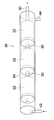
- FIG. 2 is a perspective view illustrating a configuration of elements of the water treatment apparatus according to the embodiment.
- FIG. 3 is a perspective view of a module in which the element shown in FIG. 2 is incorporated in a container.
- FIG. 4 is a front view of the element showing a state before the RO membrane of the element shown in FIG. 2 is wound.
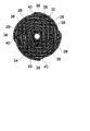
- FIG. 5 is a front view of the element shown in FIG.
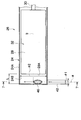
- FIG. 6 is a side cross-sectional view showing a part of the module shown in FIG.
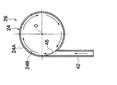
- FIG. 7A is a cross-sectional view of the module of FIG. 6 taken along line 7-7.
- FIG. 7B is a perspective view of a main part of the module of FIG.
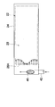
- FIG. 8 is an explanatory diagram showing an example of the flow velocity distribution of seawater generated by the rectifying mechanism.
- FIG. 9 is an explanatory view showing an example of the flow velocity distribution of seawater generated by the rectifying mechanism.
- FIG. 1 is a block diagram of a seawater desalination treatment system 20 in which a water treatment apparatus 10 according to an embodiment is incorporated.
- a seawater desalination treatment system 20 shown in FIG. 1 includes a tank 12 in which seawater is stored, a high-pressure pump 14, and a water treatment device 10. Seawater in the tank 12 is supplied to the water treatment device 10 at a high pressure by the high-pressure pump 14 and reverse osmosis treatment (desalination treatment) is performed by an RO membrane (to be described later) of the water treatment device 10, thereby desalted permeated water 16. And concentrated water 18 in which the salinity is concentrated. The permeated water 16 thus obtained is sent to the outside of the water treatment device 10.
- seawater is supplied to the water treatment apparatus 10 at a high pressure by the high pressure pump 14.
- a high pressure suction pump is connected to the permeate outlet side of the water treatment apparatus 10.
- the seawater may be introduced into the water treatment apparatus 10 from the tank 12 by this suction pump.
- you may provide both the high-pressure pump 14 and a suction pump.
- raw seawater may be used as it is, but it is preferable to use seawater that has been pretreated to remove turbid components contained in the raw seawater.
- pretreatment include use of a filter, introduction of raw seawater into a sedimentation basin, addition of a sterilizing agent such as chlorine, precipitation removal of particles in the raw seawater, and sterilization of microorganisms.
- seawater obtained by adding a flocculant such as iron chloride to the raw seawater to aggregate the turbid component and filtering it off may be used.
- the water treatment apparatus 10 connects one or a plurality of elements 22 shown in FIG. 2 in series, fills the container 24 shown in FIG. 3 into a module 26, and connects the module 26 alone or in parallel. It is constituted by doing.
- a predetermined operating pressure is applied to the module 26 by the high-pressure pump 14.
- 3 shows a module 26 in which three elements 22, 22... Are connected in series, the number of elements 22 is not limited to three.
- the container 24 is made of super stainless steel (a steel type having a PREN value (pitting corrosion coefficient) (Pitting Resistance Equivalent Number) of 40 or more) so as to withstand high pressure (5 MPa or more).
- the element 22 includes an RO membrane unit 32 including an RO membrane 28 and a treated water pipe 30 arranged around a water collection pipe 34.
- the RO membrane unit 32 has four bag-like RO membranes 28, 28... Radially connected to the outer periphery of the water collecting pipe 34. These RO membranes 28, 28. It is constituted by winding around the water collecting pipe 34 in a spiral shape.
- One end of the bag-like RO membrane 28 is opened, and the RO membrane 28 is bonded to the water collection tube 34 so that the opening communicates with the through hole 36 of the water collection tube 34 shown in FIG. Seawater, which is the water to be treated, flows through the outer surface of the RO membrane 28 and is desalted by passing through the RO membrane 28.
- reference numeral 38 in FIG. 4 is a mesh spacer disposed inside the RO membrane 28.
- the spacer 38 holds the RO membrane 28 so that the inner space of the RO membrane 28 is not crushed even if the RO membrane 28 is wound in a spiral shape.
- Reference numeral 40 denotes a mesh-like spacer disposed between the adjacent RO membranes 28 and 28. The spacers 40 are also radially bonded to the outer periphery of the water collecting pipe 34 in the same manner as the RO membrane 28.
- a pipe 42 is connected to the outer peripheral portion on one end side of the container 24.
- Seawater is supplied by the high-pressure pump 14 from the tank 12 of FIG.
- the seawater supplied into the container 24 is guided to the RO membrane unit 32 of the element 22 and sequentially passes through the RO membranes 28, 28..., And then collected in the water collecting pipe 34 as described above and from the treated water pipe 30 to the module 26. It is taken out outside.
- the concentrated water that has not permeated through the RO membranes 28, 28... Is sequentially guided to the downstream elements 22, 22, and is separated into permeated water and concentrated water in the same manner as described above, and finally the concentrated water is discharged. It is discharged from the tube 44 to the outside of the module 26.
- the concentrated water discharge pipe 44 is connected to the outer peripheral portion on the other end side of the container 24.
- the module 26 is provided with a seawater rectification structure.
- This rectifying structure is configured by providing a pipe 42 on the outer peripheral surface 24A of the container 24 in the cross-sectional view of the side surface of the module 26 shown in FIG.
- the pipe 42 is arranged in a direction in which the axis a of the pipe 42 is orthogonal to the long axis b of the container 24.
- the pipe 42 is connected to the outer peripheral surface 24A of the container 24 in a posture in which the axis a is oriented in a tangential direction with respect to the inner peripheral surface 24B of the container 24 in the cross-sectional view of the module 26 shown in FIG. 7A.
- the discharge port 46 of the pipe 42 is formed flush with the inner peripheral surface 24 ⁇ / b> B of the container 24.
- the seawater injected from the discharge port 46 of the pipe 42 flows in the container 24 as a swirl flow along the inner peripheral surface 24B of the container 24 as shown by the arrow in FIG. 7A, and the RO membranes 28, 28.
- To the inlet end face 28A (same as the inlet end face of the element 22).
- the pipe 42 is provided on the outer peripheral surface 24A of the container 24, and the axis a of the pipe 42 is provided in the tangential direction with respect to the inner peripheral surface 24B of the container 24.
- the flow velocity distribution as in the water treatment apparatus of Document 1 does not occur between the discharge port 46 of the pipe 42 and the inlet end surface 28A of the RO membrane 28.
- FIG. 8 shows the flow velocity distribution of seawater with respect to the inlet end surface 28A of the RO membrane 28 of the water treatment device 10 of the embodiment by arrows.
- the pipe 42 is provided on the outer peripheral surface of the container 24 and is provided in a tangential direction with respect to the inner peripheral surface 24 ⁇ / b> B of the container 24. It becomes a swirl flow along the inner peripheral surface 24B. For this reason, the vertical component of the seawater flow with respect to the inlet end surface 28A of the RO membrane 28 once disappears. Thereafter, the seawater moves in the axial direction of the container 24 while turning along the inner peripheral surface 24 ⁇ / b> B of the container 24.
- the axial component of the flow velocity in the axial direction of the seawater flow is substantially uniform as shown in FIG. 8, or the position near the inner peripheral surface 24B of the container 24 increases as shown in FIG. 9 when the flow velocity of the seawater is increased. .
- seawater is sufficiently exposed to the entire surface of the RO membrane 28 at the inlet end face 28A of the RO membrane 28 and moves toward the inside of the element 22 and the outlet as it is, so that the entire surface of the RO membrane 28 is efficiently obtained. Exposed to seawater. As a result, the occurrence of fouling of the RO film 28 progresses uniformly and gradually, so that the blocking time due to fouling can be reduced.
- the treatment performance of the RO membrane 28 is improved as compared with the water treatment device of Patent Document 1.
- the axis a of the pipe 42 may be slightly inclined with respect to the long axis b of the container 24. Further, the flow direction of the swirl flow may be the same as the winding direction of the RO membrane 28, but by making the direction reverse, the crevice flow pressure prevents the gap between the RO membrane 28 and the RO membrane 28 from being crushed. Therefore, seawater desalination treatment by the RO membrane 28 is stabilized. Further, the pipe 42 may be provided on a lid for closing the inlet opening of the container 24.
- Such a water treatment apparatus 10 has a high ratio (enlargement ratio) between the diameter ⁇ 1 of the discharge port 46 of the pipe 42 and the inner diameter ⁇ 2 of the vessel 24 in FIG. 6, and the inlet end surface 28A of the discharge port 46 and the RO membrane 28. This is effective when the distance L is short.
- the inner diameter ⁇ 2 of the container 24 is 5 to 10 times the diameter ⁇ 1 of the discharge port 46, and the distance L is not more than five times the inner diameter ⁇ 2 of the container 24.
- the water treatment apparatus that desalinates seawater using the RO membrane has been described, but the membrane is not limited to the RO membrane. That is, the configuration of the present invention can be applied to any apparatus that uses a membrane to treat water to be treated. Further, the water to be treated is not limited to seawater, and even a water treatment apparatus that uses a membrane such as an RO membrane to remove dissolved substances, turbidity, microorganisms, etc. in tap water can be used in the present invention. Configuration can be applied.
- SYMBOLS 10 Water treatment apparatus, 12 ... Tank, 14 ... High pressure pump, 16 ... Permeated water, 18 ... Concentrated water, 20 ... Seawater desalination processing system, 22 ... Element, 24 ... Container, 26 ... Module, 28 ... RO membrane, 30 ... treated water pipe, 32 ... RO membrane unit, 34 ... water collecting pipe, 36 ... through hole, 38 ... spacer, 40 ... spacer, 42 ... piping, 44 ... concentrated water discharge pipe, 46 ... discharge port
Landscapes
- Chemical & Material Sciences (AREA)
- Engineering & Computer Science (AREA)
- Water Supply & Treatment (AREA)
- Chemical Kinetics & Catalysis (AREA)
- Life Sciences & Earth Sciences (AREA)
- Hydrology & Water Resources (AREA)
- Environmental & Geological Engineering (AREA)
- Organic Chemistry (AREA)
- Nanotechnology (AREA)
- Separation Using Semi-Permeable Membranes (AREA)
Abstract
L'invention concerne un dispositif de traitement de l'eau (10) équipé : d'une membrane d'osmose inverse OI (28) qui assure le traitement de l'eau à traiter; d'un récipient (24) de forme cylindrique garni de ladite membrane OI (28); et d'un tuyau (42) qui alimente la surface périphérique externe du récipient (24), en eau à traiter dans la direction tangentielle à la surface périphérique interne du récipient (24). Ainsi, avec cette configuration, comme l'ensemble de la surface de la membrane OI (28) peut être exposé efficacement à l'eau à traiter, les capacités de traitement de la membrane OI (28) sont améliorées.
Applications Claiming Priority (2)
| Application Number | Priority Date | Filing Date | Title |
|---|---|---|---|
| JP2010036413A JP2011167668A (ja) | 2010-02-22 | 2010-02-22 | 水処理装置 |
| JP2010-036413 | 2010-02-22 |
Publications (1)
| Publication Number | Publication Date |
|---|---|
| WO2011102464A1 true WO2011102464A1 (fr) | 2011-08-25 |
Family
ID=44483049
Family Applications (1)
| Application Number | Title | Priority Date | Filing Date |
|---|---|---|---|
| PCT/JP2011/053506 Ceased WO2011102464A1 (fr) | 2010-02-22 | 2011-02-18 | Dispositif de traitement de l'eau |
Country Status (2)
| Country | Link |
|---|---|
| JP (1) | JP2011167668A (fr) |
| WO (1) | WO2011102464A1 (fr) |
Cited By (2)
| Publication number | Priority date | Publication date | Assignee | Title |
|---|---|---|---|---|
| EP3135374A4 (fr) * | 2014-04-24 | 2017-10-11 | Panasonic Intellectual Property Management Co., Ltd. | Membrane d'échange d'ions, corps stratifié de membrane d'échange d'ions pourvu d'une membrane d'échange d'ions, cellule électrochimique pourvue d'un corps stratifié de membrane d'échange d'ions et appareil de traitement de l'eau pourvu de la cellule électrochimique |
| US11518692B2 (en) * | 2018-01-19 | 2022-12-06 | Curt Johnson | Electrocoagulation system |
Citations (5)
| Publication number | Priority date | Publication date | Assignee | Title |
|---|---|---|---|---|
| JPS5786361A (en) * | 1980-11-20 | 1982-05-29 | Kogyo Gijutsuin | Blood treatment device with hollow fiber membrane bundle |
| JPS63205106A (ja) * | 1987-02-19 | 1988-08-24 | Toshiba Corp | ろ過器 |
| JPS6417246U (fr) * | 1987-07-17 | 1989-01-27 | ||
| JPH09103606A (ja) * | 1995-10-12 | 1997-04-22 | Miura Co Ltd | 気体分離膜モジュール |
| JP2005219023A (ja) * | 2004-02-09 | 2005-08-18 | Nitto Denko Corp | スパイラル型膜エレメント用ベッセル |
-
2010
- 2010-02-22 JP JP2010036413A patent/JP2011167668A/ja active Pending
-
2011
- 2011-02-18 WO PCT/JP2011/053506 patent/WO2011102464A1/fr not_active Ceased
Patent Citations (5)
| Publication number | Priority date | Publication date | Assignee | Title |
|---|---|---|---|---|
| JPS5786361A (en) * | 1980-11-20 | 1982-05-29 | Kogyo Gijutsuin | Blood treatment device with hollow fiber membrane bundle |
| JPS63205106A (ja) * | 1987-02-19 | 1988-08-24 | Toshiba Corp | ろ過器 |
| JPS6417246U (fr) * | 1987-07-17 | 1989-01-27 | ||
| JPH09103606A (ja) * | 1995-10-12 | 1997-04-22 | Miura Co Ltd | 気体分離膜モジュール |
| JP2005219023A (ja) * | 2004-02-09 | 2005-08-18 | Nitto Denko Corp | スパイラル型膜エレメント用ベッセル |
Cited By (2)
| Publication number | Priority date | Publication date | Assignee | Title |
|---|---|---|---|---|
| EP3135374A4 (fr) * | 2014-04-24 | 2017-10-11 | Panasonic Intellectual Property Management Co., Ltd. | Membrane d'échange d'ions, corps stratifié de membrane d'échange d'ions pourvu d'une membrane d'échange d'ions, cellule électrochimique pourvue d'un corps stratifié de membrane d'échange d'ions et appareil de traitement de l'eau pourvu de la cellule électrochimique |
| US11518692B2 (en) * | 2018-01-19 | 2022-12-06 | Curt Johnson | Electrocoagulation system |
Also Published As
| Publication number | Publication date |
|---|---|
| JP2011167668A (ja) | 2011-09-01 |
Similar Documents
| Publication | Publication Date | Title |
|---|---|---|
| JP5687561B2 (ja) | 水処理装置 | |
| CN100531870C (zh) | 膜组件及水处理系统 | |
| JPS63284328A (ja) | 給水装置 | |
| WO2012086479A1 (fr) | Dispositif de traitement par osmose inverse | |
| US10954140B2 (en) | Apparatus for generating cavitation in a liquid | |
| JP6344114B2 (ja) | 水処理装置及び水処理設備の洗浄方法 | |
| JP2011167668A (ja) | 水処理装置 | |
| WO2011102443A1 (fr) | Dispositif de traitement de l'eau | |
| JP2014184438A (ja) | 逆浸透処理装置 | |
| KR101395158B1 (ko) | 해수를 이용한 선박용 음용수와 냉각수 제조장치 및 그 방법 | |
| KR102357812B1 (ko) | 역삼투장치 및 이를 포함하는 해수 담수화 시스템 | |
| US11648496B2 (en) | Treatment module and operating method therefor | |
| JPWO2014126156A1 (ja) | 膜分離処理方法および膜分離処理システム | |
| KR20220048616A (ko) | 파울링 저감을 위한 수처리 장치 및 방법 | |
| WO2011102438A1 (fr) | Dispositif de traitement de l'eau | |
| KR102391733B1 (ko) | 역삼투장치 및 이를 포함하는 해수 담수화 시스템 | |
| KR102749842B1 (ko) | 전처리수를 이용할 수 있는 정수시스템 | |
| KR102122007B1 (ko) | 무 필터방식의 정수장치 | |
| US10876085B2 (en) | System and method for purification of drinking water, ethanol and alcohol beverages of impurities | |
| JP2010064032A (ja) | 浄水装置 | |
| JP5996057B2 (ja) | 逆浸透処理装置 | |
| JP2016215205A (ja) | 逆浸透処理装置 | |
| JP2017159274A (ja) | 液体処理装置 | |
| Berde et al. | Pilot Testing Advanced Treatment Technologies for High Quality Recycled Water Production | |
| CN110697923A (zh) | 智能净水系统和智能净水方法 |
Legal Events
| Date | Code | Title | Description |
|---|---|---|---|
| 121 | Ep: the epo has been informed by wipo that ep was designated in this application |
Ref document number: 11744750 Country of ref document: EP Kind code of ref document: A1 |
|
| DPE1 | Request for preliminary examination filed after expiration of 19th month from priority date (pct application filed from 20040101) | ||
| NENP | Non-entry into the national phase |
Ref country code: DE |
|
| 122 | Ep: pct application non-entry in european phase |
Ref document number: 11744750 Country of ref document: EP Kind code of ref document: A1 |