WO2011102482A1 - Mur de soutènement en forme de l et unité de mur de soutènement en forme de l - Google Patents
Mur de soutènement en forme de l et unité de mur de soutènement en forme de l Download PDFInfo
- Publication number
- WO2011102482A1 WO2011102482A1 PCT/JP2011/053558 JP2011053558W WO2011102482A1 WO 2011102482 A1 WO2011102482 A1 WO 2011102482A1 JP 2011053558 W JP2011053558 W JP 2011053558W WO 2011102482 A1 WO2011102482 A1 WO 2011102482A1
- Authority
- WO
- WIPO (PCT)
- Prior art keywords
- retaining wall
- bottom plate
- wall
- shaped retaining
- pressure receiving
- Prior art date
- Legal status (The legal status is an assumption and is not a legal conclusion. Google has not performed a legal analysis and makes no representation as to the accuracy of the status listed.)
- Ceased
Links
Images


Classifications
-
- E—FIXED CONSTRUCTIONS
- E02—HYDRAULIC ENGINEERING; FOUNDATIONS; SOIL SHIFTING
- E02D—FOUNDATIONS; EXCAVATIONS; EMBANKMENTS; UNDERGROUND OR UNDERWATER STRUCTURES
- E02D29/00—Independent underground or underwater structures; Retaining walls
- E02D29/02—Retaining or protecting walls
Definitions
- the present invention relates to an L-shaped retaining wall and an L-shaped retaining wall unit that are used as earth retaining in land preparation or the like.
- an L-shaped retaining wall consisting of a vertical wall installed in the vertical direction and a bottom plate extending in the horizontal direction starting from the lower end of the vertical wall is used.
- This L-type retaining wall generally has a precast reinforced concrete structure, and is used by installing a pre-manufactured L-type retaining wall on a foundation constructed on the ground.
- Such an L-shaped retaining wall is formed so that the vertical wall and the bottom plate are orthogonal to each other (a right-angled L-shaped retaining wall), and formed so that the vertical wall and the bottom plate form an obtuse angle of about 105 degrees. (Obtuse angle L-type retaining wall).
- the obtuse L-shaped retaining wall is more stable and stronger than the right-angled L-shaped retaining wall in that the horizontal component of the bottom plate reaction force can be used as a resistance to sliding (sliding in the horizontal direction). Is also known to be excellent (see, for example, Patent Document 1).
- the obtuse angle L-type retaining wall can be reduced in weight while improving stability against sliding and falling compared to the right-angled L-type retaining wall. Moreover, since the depth of penetration on the vertical wall side can be reduced, the required excavation amount can be reduced.
- the conventional obtuse L-shaped retaining wall has stability superior to that of the right-angled L-shaped retaining wall, the stability when an excessive load is applied due to, for example, an earthquake is not sufficient, and recent large earthquakes Along with the heightened awareness of disaster prevention that accompanies outbreaks, further improvements in the stability of retaining walls are desired.
- the present invention intends to provide an L-type retaining wall and an L-shaped retaining wall unit with improved stability against sliding and falling.
- the present invention is an L-shaped retaining wall comprising a vertical wall installed in the vertical direction and a bottom plate extending in the horizontal direction with the lower end of the vertical wall as a base end, and the upper surface of the bottom plate is It is formed to be inclined so as to form an obtuse angle with respect to the vertical wall, and a pressure receiving wall that receives a part of earth pressure on the bottom plate protrudes upward at a tip portion of the bottom plate. It is an L-shaped retaining wall.
- the present invention is also characterized in that, in the L-type retaining wall of the above means, the pressure receiving surface of the pressure receiving wall is inclined so as to be gradually separated from the vertical wall from the base end to the tip end of the pressure receiving wall. To do.
- the present invention is also characterized in that, in the L-shaped retaining wall of the above means, the upper surface of the bottom plate is formed so as to form an angle of 95 to 115 degrees with respect to the vertical wall.
- the present invention is also characterized in that, in the L-type retaining wall of the above means, the pressure receiving wall is formed integrally with the bottom plate.
- the present invention is also characterized in that, in the L-type retaining wall of the above means, the pressure receiving wall is constituted by another member attached to the bottom plate so as to be swingable and fixable at a predetermined angle.
- the present invention is also characterized in that, in the L-shaped retaining wall of the above means, the lower surface of the bottom plate is formed in a stepped shape in which a plurality of horizontal planes are arranged at different heights along the upper surface of the bottom plate.
- the lower surface of the bottom plate is positioned at a position lower than the first horizontal surface on the first horizontal surface provided on the base end side of the bottom plate and on the distal end side of the bottom plate. And a second horizontal plane provided.
- a substantially wedge-shaped fixing member is fixed to a mounting surface formed so that the lower surface of the bottom plate is inclined so as to form an obtuse angle with respect to the vertical wall.
- a substantially wedge-shaped fixing member is fixed to a mounting surface formed so that the lower surface of the bottom plate is inclined so as to form an obtuse angle with respect to the vertical wall.
- the present invention also includes an L-type retaining wall of the above means, and a base portion composed of a plurality of sandbags laid on the ground side in accordance with the bottom surface shape of the bottom plate of the L-shaped retaining wall.
- the L-type retaining wall unit is composed of a plurality of sandbags laid on the ground side in accordance with the bottom surface shape of the bottom plate of the L-shaped retaining wall.
- the base portion is configured in a step shape so that a side surface of a part of the sandbag faces a step portion between the plurality of horizontal surfaces of the bottom plate. It is characterized by that.
- the sandbag connects a rectangular parallelepiped bag, a rectangular guide frame accommodated in the sandbag bag, and the adjacent guide frames.
- a connecting member, and the base portion is configured by stacking a plurality of the sandbags arranged in a lattice in a state where adjacent sandbags are connected to each other by the connecting member.
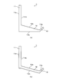
- (A) It is a perspective view of the L-shaped retaining wall of embodiment of this invention.
- (B) It is a side view of an L-shaped retaining wall. It is the perspective view which showed the L-shaped retaining wall unit of embodiment of this invention. It is the figure which showed the sandbag which comprises a base part. It is the figure which showed an example of the state which installed the L-shaped retaining wall unit as a earth retaining.
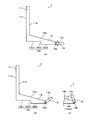
- (A) And (b) It is the figure which showed the example which comprised the pressure receiving wall from another member from the L-type retaining wall main body.
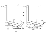
- (A) And (b) It is the figure which showed the example which formed the lower surface of the baseplate of the L-shaped retaining wall in the shape similar to the conventional L-shaped retaining wall. It is the figure which showed the example which formed the lower surface of the baseplate of the L-shaped retaining wall in step shape by fixing another member.
- FIG. 1A is a perspective view of the L-shaped retaining wall 1 of the present embodiment
- FIG. 1B is a side view of the L-shaped retaining wall 1.
- the L-type retaining wall 1 has a precast reinforced concrete structure. As shown in these drawings, the L-type retaining wall 1 extends in the horizontal direction with the vertical wall 11 extending in the vertical direction and the lower end of the vertical wall 11 as the base end.
- the bottom plate 12 and a pressure receiving wall 13 that protrudes obliquely upward from the front end portion of the bottom plate 12.
- the vertical wall 11 is a portion installed in the vertical direction when the L-shaped retaining wall 1 is used as a retaining wall.
- the surface on the opposite side of the bottom plate 12 is the front surface 11a exposed to the outside, and the front surface 11a is a smooth flat surface or a surface that is appropriately decorated.
- the back surface 11b of the vertical wall 11 is appropriately provided with a reinforcing rib, a connecting portion for connecting adjacent L-shaped retaining walls 1 or the like as necessary.
- the vertical wall 11 is provided with a drain hole penetrating between the front surface 11a and the back surface 11b at an appropriate position as necessary.
- the bottom plate 12 extends in a substantially horizontal direction from the back surface 11 b side of the lower end portion of the vertical wall 11.
- the upper surface 12a of the bottom plate 12 is formed so as to form an angle ⁇ with respect to the vertical wall.
- the angle ⁇ is not particularly limited, and can be set as appropriate according to the internal friction angle of the soil particles to be buried on the bottom plate 12. However, considering the case of using general soil and installing (covering soil) on the upper surface 12a of the bottom plate 12, the angle ⁇ is preferably set within a range of 95 to 115 degrees, It is more preferable to set within the range.
- the bottom surface 12b of the bottom plate 12 includes a first horizontal plane 12b1 provided on the base end side of the bottom plate 12, a second horizontal plane 12b2 provided on the distal end side of the bottom plate 12, and a step between the first horizontal plane 12b1 and the second horizontal plane 12b2. 12b3, and has a stepped shape along the upper surface 12b.
- the first horizontal plane 12b1 and the second horizontal plane 12b2 are formed so as to be substantially orthogonal to the vertical wall, that is, substantially horizontal when installed, and the second horizontal plane 12b2 is the first horizontal plane 12b1. It is provided at a lower position.
- the step portion 12b3 is formed substantially parallel to the vertical wall 11, that is, in a substantially vertical direction.
- the step portion 12b3 is not limited to this and may be formed obliquely.
- Reinforcing ribs and connecting portions are provided on the upper surface 12a of the bottom plate 12 as necessary.
- the bottom plate 12 may be provided with a hole for injecting mortar or the like below the lower surface 12b after the L-type retaining wall 1 is installed on the foundation.
- the pressure receiving wall 13 receives a part of the earth pressure by inclining the upper surface 12a of the bottom plate 12.
- the first horizontal plane 12b1 and the second horizontal plane 12b2 that are substantially horizontal when installed on the lower surface 12b of the bottom plate 12
- the construction of the foundation is facilitated, and a plurality of L-type retaining walls 1 that are installed adjacent to each other. This makes it easy to adjust the height and face of the machine and improve the workability of the installation work.
- the step portion 12b3 resistance to sliding is generated in a deep portion of the soil, and stability against sliding is improved.
- the pressure receiving wall 13 has a solidified region on the bottom plate 12 where the soil particles are solidified by receiving the restraining pressure by receiving the soil particles sliding down on the upper surface 12a of the bottom plate 12 which is an inclined surface. It is for generating.
- the pressure receiving wall 13 protrudes obliquely upward from the front end portion of the bottom plate 12.
- the pressure receiving surface 13a which is a surface which receives earth pressure in the pressure receiving wall 13 is in the state inclined so that it may gradually separate from the said vertical wall 11 toward the front-end
- the earth pressure (restraint pressure) applied to the pressure receiving wall 13 is increased by inclining the pressure receiving surface 13a in this way.
- the inclination angle of the pressure receiving surface 13a is not particularly limited, and may be set as appropriate according to the internal friction angle of the soil particles to be backfilled on the bottom plate 12.
- the shape, length, material, and the like of the pressure receiving wall 13 are not particularly limited, and may be any shape as long as the pressure receiving surface 13a can be appropriately inclined. .
- FIG. 2 is a perspective view showing the L-shaped retaining wall unit 2.
- the L-type retaining wall unit 2 includes an L-shaped retaining wall 1 and a base portion 3 that constitutes a foundation that is laid on the ground side and on which the L-shaped retaining wall 1 is placed.
- the base portion 3 is configured in a stepped manner in accordance with the lower surface 12b of the bottom plate 12 of the L-type retaining wall 1 by arranging a plurality of rectangular parallelepiped sandbags 30 in a lattice shape and stacking a plurality of steps.
- FIG. 3 is a view showing a sandbag 30 that constitutes the foundation 3.
- the sandbag 30 includes a rectangular parallelepiped sandbag 31, a rectangular guide frame 32 housed inside the sandbag 31, and a connecting member 33 that connects adjacent guide frames 32 to each other. It has.
- the guide frame 32 functions as a guide for aligning a plurality of sandbags placed on the bottom of the sandbag bag 31, and is opposed to four plate-like ribs 32a that are combined with each other to form a rectangular frame. It is comprised from the beam 32b which connects the plate-shaped rib 32a to perform and maintains the shape of the guide frame 32.
- FIG. The guide frame 32 is fixed to the sandbag bag 31 by connecting a fixing piece (not shown) from the outside of the sandbag bag 31 to the guide frame 32 through the sandbag bag 31.
- the connecting member 33 includes claws 33a at both ends, and the adjacent guide frames 32 are connected to each other by engaging the claws 33a with the guide frames 32. Thereby, the plurality of sandbags 30 arranged in a lattice form are in a state where adjacent sandbags 30 are connected to each other.
- the connection member 33 connects the sandbags 30 adjacent to each other as described above, thereby integrating the plurality of sandbags 30 and improving the strength.
- the connecting member 33 has a function of ensuring an appropriate gap between the sandbags 30 when the sandbags 30 are arranged.
- the sandbag 30 of the present embodiment is a patented invention by a part of the inventors of the present invention.
- Japanese Patent No. 4019100 refers to Japanese Patent No. 4019100.
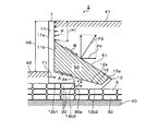
- FIG. 4 is a view showing an example of a state where the L-type retaining wall unit 2 is installed as a retaining wall.
- the foundation portion 3 is configured by first arranging and stacking a plurality of sandbags 30 on the ground 40.
- the sandbags 30 may be stacked in a line in the vertical direction, or the positions of the sandbags 30 may be shifted and stacked in a staggered manner.
- the number of steps on which the sandbags 30 are stacked may be appropriately set according to the state of the ground 40.
- the sandbag 30 may be disposed only directly under the L-shaped retaining wall 1. In this case, the amount of excavation can be reduced and the number of work steps can be reduced.
- a step 34 is formed in accordance with the shape of the lower surface 12b of the bottom plate 12 of the L-type retaining wall 1 (that is, the first horizontal surface 12b1, the second horizontal surface 12b2, and the step portion 12b3).
- This step 34 may be formed by a single-stage sandbag 30 as shown in the figure, or when the size of the sandbag 30 is smaller than the L-shaped retaining wall 1, it is formed by a plurality of stages of sandbag 30. May be.
- the L-shaped retaining wall 1 is placed on the foundation part 3 in accordance with the shape of the step 34 on the upper part of the foundation part 3. Specifically, the L-shaped retaining wall 1 is placed in a state where the step 12b3 of the bottom 12 of the L-shaped retaining wall 1 is opposed to the side surface 30a of the sandbag 30 in the step 34 portion of the base portion 3. At this time, mortar, gravel, or the like is filled between the lower surface 12b of the L-shaped retaining wall 1 and the sandbag 30 of the foundation 3 as necessary. In addition, when performing height alignment or surface alignment between adjacent L-shaped retaining walls 1, a spacer or the like is appropriately inserted between the first horizontal plane 12 b 1 or the second horizontal plane 12 b 2 and the base portion 3. Finally, the back soil 41 is covered on the back surface 11b side of the vertical wall 11 of the L-shaped retaining wall 1, and the front soil 42 is covered on the front surface 11a side.
- the foundation part 3 is constituted by a plurality of sandbags 30, it is possible to easily construct the foundation part 3 regardless of the state of the ground 40.
- the sandbag 30 since the sandbag 30 includes the guide frame 32 and the connecting member 33, the sandbag 30 can be connected and arranged quickly at an appropriate interval even if the ground 40 is soft. As a result, the foundation 3 having sufficient strength can be constructed on the soft ground 40.
- the foundation part 30 comprised from several sandbags 30 unlike the conventional obtuse angle L-type retaining wall. It can be easily installed on top. Moreover, the force F2 received from the side surface 30a of the sandbag 30 with which the step part 12b3 opposes can be stably exhibited as the resistance force with respect to sliding with the force F1 which the front 11a lower part of the vertical wall 11 receives from the front soil 42.
- the L-type retaining wall 1 of the present embodiment is provided with the pressure-receiving wall 13 so that a part of the earth pressure of the back soil 41 on the bottom plate 12 is received by the pressure-receiving surface 13a, and the stability of the L-type retaining wall 1 is improved. I try to increase it. Specifically, the soil particles on the bottom plate 12 slide along the inclination of the upper surface 12a in the direction indicated by the arrow A in the figure, but this slip is limited by the pressure receiving surface 13a, and the soil particles are shown in the figure. It will be restrained in the solidified region 50.
- the upper surface 51 of the solidified region 50 is an inclined surface inclined at an angle based on the internal friction angle of the back soil 41. The soil particles in the solidified region 50 are solidified due to the generation of interparticle friction by the upper back soil 41 and the earth pressure due to the overload acting as additional stress.
- the solidified region 50 that is solidified integrally with the L-type retaining wall 1 by the earth particles being compacted is generated on the bottom plate 12. Accordingly, the back soil 41 slides in the direction indicated by the arrow B in FIG. As a result, as shown in the figure, the height H1 at which the vertical wall 11 receives the back soil 41 and the earth pressure P due to the overload is in a range smaller than the retaining height H2, so that the L-shaped retaining wall 1 The earth pressure applied to the vertical wall 11 will be reduced.
- the horizontal component F4 of the bottom plate reaction force F3 is slid similarly to the conventional obtuse angle L-type retaining wall. It can be used as a resistance force against.
- the solidification region 50 is generated on the bottom plate 12 by providing the pressure receiving wall 13, and the stability of the L-type retaining wall 1 against sliding and falling is further enhanced. Further, even when an excessive load is applied to the L-type retaining wall 1 due to an earthquake or the like, for example, this load can be appropriately dispersed by the solidified region 50 and the earth pressure P received by the vertical wall 11 can be reduced. Therefore, it is possible to provide stability that is higher than that of the conventional obtuse angle L-type retaining wall.
- the pressure receiving wall 13 is formed integrally with the bottom plate 12, that is, the L-type retaining wall 1 is precast into a shape having the pressure receiving wall 13 on the bottom plate 12, but the pressure receiving wall 13 is L-shaped. You may make it comprise from a member different from the retaining wall 1 main body.
- FIG. 5 (a) and 5 (b) are views showing an example in which the pressure receiving wall 13 is formed of a member different from the L-type retaining wall 1 main body.
- the pressure receiving wall 13 is swingably attached to the distal end portion of the bottom plate 12 via a swing pin 13b as shown in FIG.
- the pressure receiving wall 13 is fixed at a predetermined angle by a known method such as bolt, engagement, adhesion, or the like. Fixed.
- the pressure receiving wall 13 is formed of a member different from the main body of the L-shaped retaining wall 1 and is swingably mounted, whereby a plurality of L-shaped retaining walls 1 are stored or stored during transportation of the L-shaped retaining wall 1. Can be stacked in a compact manner without being affected by the pressure receiving wall 13.
- the inclination angle of the pressure receiving surface 13a can be set as appropriate, and the shape and length of the pressure receiving wall 13 can be easily changed.
- the pressure receiving wall 13 in this case may be comprised from reinforced concrete like the L-type retaining wall 1 main body, and may be comprised from metals, such as iron, and another material.
- the pressure receiving wall 13 as another member may be fixed to the main body of the L-type retaining wall 1 so as to be detachable by bolts, engagement, or the like, instead of being fixed so as to be swingable.
- the lower surface 12b of the bottom plate 12 of the L-shaped retaining wall 1 is formed in a stepped shape.
- the present invention is not limited to this, and the lower surface 12b is formed with a conventional L-shaped retaining wall. You may make it comprise in the shape similar to a wall.
- FIGS. 5A and 5B are diagrams showing an example in which the lower surface 12b of the bottom plate 12 of the L-shaped retaining wall 1 is formed in the same shape as a conventional L-shaped retaining wall.
- FIG. 8B shows an example in which the lower surface 12 b is formed to form an obtuse angle with the vertical wall 11.
- the L-type retaining wall 1 may be configured by fixing the pressure receiving wall 13 as a separate member to the tip of the bottom plate of the existing obtuse L-shaped retaining wall with a bolt or the like. Further, the L-type retaining wall 1 may be configured by adding an inclined surface to the upper surface of the bottom plate of the existing right-angle L-shaped retaining wall and fixing the pressure receiving wall 13 as another member to the tip portion.
- FIG. 7 is a view showing an example in which the lower surface 12b of the bottom plate 12 of the L-shaped retaining wall 1 is formed in a step shape by fixing another member.
- the L-shaped retaining wall 1 is fixed in a substantially wedge shape to a mounting surface 12c on the lower side of the bottom plate 12 that is formed so as to form an obtuse angle with respect to the vertical wall 11.
- the member 14 By fixing the member 14, the lower surface 12b of the bottom plate 12 is formed in a step shape.
- a known fixing method such as a bolt, engagement, or adhesion can be employed.
- the pressure receiving wall 13 may be formed by fixing another member.
- the L-type retaining wall 1 may be easily manufactured and transported.
- the L-type retaining wall 1 of the present invention can be configured by utilizing an existing obtuse L-shaped retaining wall.
- the mounting surface 12c in this case does not have to be an inclined surface so that all surfaces form an obtuse angle with respect to the vertical wall 11, and as shown in the figure, for example, a surface orthogonal to the vertical wall 11 Etc., surfaces with different angles may be included.
- a protrusion or the like for fixing the fixing member 14 to the attachment surface 12c may be provided.
- the L-type retaining wall 1 includes the vertical wall 11 installed in the vertical direction, the bottom plate 12 extending in the horizontal direction with the lower end portion of the vertical wall 11 as the base end, An upper surface 12 a of the bottom plate 12 is formed so as to be inclined with an obtuse angle with respect to the vertical wall 11, and an earth pressure on the bottom plate 12 is set at the tip of the bottom plate 12.
- a pressure receiving wall 13 that receives the portion protrudes upward.
- Such a configuration makes it possible to reduce the earth pressure P applied to the vertical wall 11, and to improve the stability against sliding and falling more than before.
- the load can be appropriately dispersed and the earth pressure P received by the vertical wall 11 can be reduced. It becomes possible to provide stability more than an obtuse L-shaped retaining wall.
- the height and width of the pressure receiving wall 13 can be set to appropriate dimensions according to the nature of the back soil 41 to be backfilled and the required degree of stability.
- the pressure receiving surface 13a of the pressure receiving wall 13 is inclined so as to be gradually separated from the vertical wall 11 from the base end to the tip end of the pressure receiving wall 13.
- the inclination angle of the pressure receiving surface 13a can be set to an appropriate angle so as to maximize the restraining effect in accordance with the soil particles of the ground installed on the bottom plate 12. That is, the pressure receiving surface 13a may be inclined so as to gradually approach the vertical wall 11 from the proximal end to the distal end of the pressure receiving wall 13 depending on the properties of the soil particles, or is parallel to the vertical wall 11, for example. May be.
- the solidified region 50 that contributes to the improvement of stability is reliably generated on the bottom plate 12. be able to.
- the pressure receiving wall 13 is formed integrally with the bottom plate 12, the pressure receiving wall 13 can be configured to be lightweight while having sufficient strength.
- the pressure receiving wall 13 may be constituted by another member attached to the bottom plate 12 so as to be swingable and fixed at a predetermined angle.
- the plurality of L-shaped retaining walls 1 can be stored and transported in a compactly stacked state.
- the inclination angle of the pressure receiving surface 13a can be set to an appropriate angle according to the soil particles of the ground installed on the bottom plate 12, and the shape and length of the pressure receiving wall 13 can be easily changed. .
- the lower surface 12b of the bottom plate 12 is formed in a staircase shape in which a plurality of horizontal surfaces 12b1 and 12b2 are arranged at different heights along the upper surface 12a of the bottom plate 12. For this reason, the workability
- the lower surface 12b of the bottom plate 12 is formed in a two-step shape including the first horizontal surface 12b1, the second horizontal surface 12b2, and the step portion 12b3.
- the present invention is not limited to this.
- the lower surface 12b may be configured in three or more steps.
- this invention is not limited to this, L on the general foundation by concrete placement etc.
- the mold retaining wall 1 may be installed.
- the bottom surface 12b of the bottom plate 12 has a first horizontal plane 12b1 provided on the base end side of the bottom plate 12, and a second horizontal plane 12b2 provided at a position lower than the first horizontal plane 12b1 on the distal end side of the bottom plate 12. Configured. That is, in the present invention, the above-described effects can be exhibited with a relatively simple configuration, and the manufacturing cost of the L-shaped retaining wall 1 can be reduced.
- the lower surface 12b of the bottom plate 12 is formed in a step shape by fixing a substantially wedge-shaped fixing member 14 to a mounting surface 12c formed to be inclined with an obtuse angle with respect to the vertical wall 11. It may be.
- the L-type retaining wall 1 may be easily manufactured and transported.
- the L-type retaining wall unit 2 includes a plurality of sandbags 30 laid on the ground 40 side in accordance with the shape of the L-shaped retaining wall 1 and the lower surface 12b of the bottom plate 12 of the L-shaped retaining wall 1.
- a basic part 3 made of By setting it as such a structure, irrespective of the state of the ground 40, the base part 3 can be constructed
- the base part 3 is comprised in step shape so that the side surface 30a of some sandbags 30 may oppose the step part 12b3 between the some horizontal surfaces 12b1 and 12b2 of the baseplate 12.
- FIG. 12 b 3 and the side surface 30 a of the sandbag 30 can stably exert a resistance to sliding, and the stability of the L-type retaining wall 1 can be further enhanced.
- the sandbag 30 includes a rectangular parallelepiped sandbag 31, a rectangular guide frame 32 housed in the sandbag 31, and a connecting member 33 that connects adjacent guide frames 32 to each other, and a base portion 3 is configured by stacking a plurality of sandbags 30 arranged in a lattice in a state where adjacent sandbags 30 are connected to each other by a connecting member 33.
- the sandbag 30 can be laid very easily regardless of the state of the ground 40. Moreover, since the sandbag 30 can be arrange
- the L-type retaining wall and the L-shaped retaining wall unit of the present invention are not limited to the above-described embodiments, and do not depart from the spirit of the present invention. Of course, various changes can be made.
- the L-type retaining wall and the L-type retaining wall unit of the present invention can be used in various civil engineering fields in addition to land creation.
Landscapes
- Engineering & Computer Science (AREA)
- Environmental & Geological Engineering (AREA)
- Life Sciences & Earth Sciences (AREA)
- General Life Sciences & Earth Sciences (AREA)
- Mining & Mineral Resources (AREA)
- Paleontology (AREA)
- Civil Engineering (AREA)
- General Engineering & Computer Science (AREA)
- Structural Engineering (AREA)
- Retaining Walls (AREA)
Abstract
L'invention porte sur un mur de soutènement en forme de L et sur une unité de mur de soutènement en forme de L tels que la stabilité contre le glissement et le basculement est améliorée. Ce mur de soutènement en forme de L (1) comprend une paroi verticale (11) qui est installée verticalement, et une plaque inférieure (12) qui est disposée de façon à s'étendre horizontalement à partir de l'extrémité inférieure de la paroi verticale (11). La surface supérieure (12a) de la plaque inférieure (12) est formée en oblique de façon à présenter un angle obtus par rapport à la paroi verticale (11). Au bord de la plaque inférieure (12), une paroi de pression (13), qui est soumise à une partie de la pression du sol agissant sur la plaque inférieure (12), est disposée de façon à faire saillie vers le haut.
Applications Claiming Priority (2)
| Application Number | Priority Date | Filing Date | Title |
|---|---|---|---|
| JP2010001069U JP3159236U (ja) | 2010-02-22 | 2010-02-22 | L型擁壁およびl型擁壁ユニット |
| JP2010-001069U | 2010-02-22 |
Publications (1)
| Publication Number | Publication Date |
|---|---|
| WO2011102482A1 true WO2011102482A1 (fr) | 2011-08-25 |
Family
ID=44483067
Family Applications (1)
| Application Number | Title | Priority Date | Filing Date |
|---|---|---|---|
| PCT/JP2011/053558 Ceased WO2011102482A1 (fr) | 2010-02-22 | 2011-02-18 | Mur de soutènement en forme de l et unité de mur de soutènement en forme de l |
Country Status (2)
| Country | Link |
|---|---|
| JP (1) | JP3159236U (fr) |
| WO (1) | WO2011102482A1 (fr) |
Cited By (1)
| Publication number | Priority date | Publication date | Assignee | Title |
|---|---|---|---|---|
| WO2022246941A1 (fr) * | 2021-05-26 | 2022-12-01 | 上海斋喜工程技术有限公司 | Élément de paroi de protection de génie civil |
Families Citing this family (1)
| Publication number | Priority date | Publication date | Assignee | Title |
|---|---|---|---|---|
| KR102434362B1 (ko) * | 2020-07-08 | 2022-08-19 | (주)동명기술공단종합건축사사무소 | 프리캐스트 조립식 l형 옹벽 구조물 및 그 시공방법 |
Citations (3)
| Publication number | Priority date | Publication date | Assignee | Title |
|---|---|---|---|---|
| JPH01102234U (fr) * | 1987-12-24 | 1989-07-10 | ||
| JPH0215640U (fr) * | 1988-07-11 | 1990-01-31 | ||
| JP2000080637A (ja) * | 1998-06-24 | 2000-03-21 | Kuraray Co Ltd | 地盤補強構造物及び地盤補強工法 |
-
2010
- 2010-02-22 JP JP2010001069U patent/JP3159236U/ja not_active Expired - Lifetime
-
2011
- 2011-02-18 WO PCT/JP2011/053558 patent/WO2011102482A1/fr not_active Ceased
Patent Citations (3)
| Publication number | Priority date | Publication date | Assignee | Title |
|---|---|---|---|---|
| JPH01102234U (fr) * | 1987-12-24 | 1989-07-10 | ||
| JPH0215640U (fr) * | 1988-07-11 | 1990-01-31 | ||
| JP2000080637A (ja) * | 1998-06-24 | 2000-03-21 | Kuraray Co Ltd | 地盤補強構造物及び地盤補強工法 |
Cited By (1)
| Publication number | Priority date | Publication date | Assignee | Title |
|---|---|---|---|---|
| WO2022246941A1 (fr) * | 2021-05-26 | 2022-12-01 | 上海斋喜工程技术有限公司 | Élément de paroi de protection de génie civil |
Also Published As
| Publication number | Publication date |
|---|---|
| JP3159236U (ja) | 2010-05-13 |
Similar Documents
| Publication | Publication Date | Title |
|---|---|---|
| US8721228B2 (en) | Foundation-unit structure of structural object such as retaining wall, structure of upper and lower boundaries of retaining wall, and retaining wall | |
| KR101652163B1 (ko) | 옹벽용 콘크리트 패널 및 이를 이용한 옹벽 시공방법 | |
| KR102220613B1 (ko) | 자립식 옹벽 시공방법 | |
| US6913418B2 (en) | Underwater building unit and methods of installation and application thereof | |
| JP3159236U (ja) | L型擁壁およびl型擁壁ユニット | |
| KR101876842B1 (ko) | 인조패널이 부착된 보강토 옹벽블럭 및 그 시공방법 | |
| KR20100136292A (ko) | 토목구조물용 블록, 토목구조물용 블록의 고정 방법 및 상기 블록을 이용한 블록 조적식 토목구조물의 시공방법 | |
| KR101365061B1 (ko) | 성토부의 지오그리드 설치 장치 | |
| KR101265079B1 (ko) | 조립식 옹벽 세그먼트 구조체 및 조립식 옹벽 구조물 | |
| KR101072286B1 (ko) | 조립식 옹벽 | |
| JP3159235U (ja) | L型擁壁およびl型擁壁ユニット | |
| KR101221118B1 (ko) | 건축공사용 흙막이시설 | |
| KR101584738B1 (ko) | 3점에서 지지되는 자연 편석을 이용한 옹벽구조 | |
| JP2016003550A (ja) | 石積み壁の補強構造及び方法 | |
| KR101148228B1 (ko) | 강성그리드가 구비된 옹벽블럭의 장착구조 | |
| KR101065726B1 (ko) | 조립식 옹벽 | |
| KR20120125109A (ko) | 토사백 연결구 | |
| JP7115817B2 (ja) | 大型土嚢を用いた補強土壁及び大型土嚢を用いた土留め方法 | |
| KR101188590B1 (ko) | 후방 돌출 경사판을 구비한 프리캐스트 콘크리트 옹벽 | |
| KR101005352B1 (ko) | 지오그리드를 이용한 옹벽 | |
| JP6514985B2 (ja) | 土留め壁補強構造 | |
| KR102391434B1 (ko) | Eps 블록들을 이용한 조경 구조체 및 그의 시공 방법 | |
| JP7191754B2 (ja) | 駅ホームの補強構造 | |
| CN111511992A (zh) | 薄而稳定的分段式墙块以及土壤加固系统和方法 | |
| JP5800765B2 (ja) | 落石防止構造 |
Legal Events
| Date | Code | Title | Description |
|---|---|---|---|
| 121 | Ep: the epo has been informed by wipo that ep was designated in this application |
Ref document number: 11744768 Country of ref document: EP Kind code of ref document: A1 |
|
| DPE1 | Request for preliminary examination filed after expiration of 19th month from priority date (pct application filed from 20040101) | ||
| NENP | Non-entry into the national phase |
Ref country code: DE |
|
| 122 | Ep: pct application non-entry in european phase |
Ref document number: 11744768 Country of ref document: EP Kind code of ref document: A1 |