WO2011102637A2 - 원터치식 배관 연결장치 - Google Patents
원터치식 배관 연결장치 Download PDFInfo
- Publication number
- WO2011102637A2 WO2011102637A2 PCT/KR2011/001016 KR2011001016W WO2011102637A2 WO 2011102637 A2 WO2011102637 A2 WO 2011102637A2 KR 2011001016 W KR2011001016 W KR 2011001016W WO 2011102637 A2 WO2011102637 A2 WO 2011102637A2
- Authority
- WO
- WIPO (PCT)
- Prior art keywords
- pipe
- close contact
- hole
- ring
- rib
- Prior art date
- Legal status (The legal status is an assumption and is not a legal conclusion. Google has not performed a legal analysis and makes no representation as to the accuracy of the status listed.)
- Ceased
Links
Images


Classifications
-
- F—MECHANICAL ENGINEERING; LIGHTING; HEATING; WEAPONS; BLASTING
- F16—ENGINEERING ELEMENTS AND UNITS; GENERAL MEASURES FOR PRODUCING AND MAINTAINING EFFECTIVE FUNCTIONING OF MACHINES OR INSTALLATIONS; THERMAL INSULATION IN GENERAL
- F16L—PIPES; JOINTS OR FITTINGS FOR PIPES; SUPPORTS FOR PIPES, CABLES OR PROTECTIVE TUBING; MEANS FOR THERMAL INSULATION IN GENERAL
- F16L23/00—Flanged joints
- F16L23/02—Flanged joints the flanges being connected by members tensioned axially
- F16L23/024—Flanged joints the flanges being connected by members tensioned axially characterised by how the flanges are joined to, or form an extension of, the pipes
-
- F—MECHANICAL ENGINEERING; LIGHTING; HEATING; WEAPONS; BLASTING
- F16—ENGINEERING ELEMENTS AND UNITS; GENERAL MEASURES FOR PRODUCING AND MAINTAINING EFFECTIVE FUNCTIONING OF MACHINES OR INSTALLATIONS; THERMAL INSULATION IN GENERAL
- F16L—PIPES; JOINTS OR FITTINGS FOR PIPES; SUPPORTS FOR PIPES, CABLES OR PROTECTIVE TUBING; MEANS FOR THERMAL INSULATION IN GENERAL
- F16L37/00—Couplings of the quick-acting type
- F16L37/08—Couplings of the quick-acting type in which the connection between abutting or axially overlapping ends is maintained by locking members
- F16L37/084—Couplings of the quick-acting type in which the connection between abutting or axially overlapping ends is maintained by locking members combined with automatic locking
- F16L37/092—Couplings of the quick-acting type in which the connection between abutting or axially overlapping ends is maintained by locking members combined with automatic locking by means of elements wedged between the pipe and the frusto-conical surface of the body of the connector
- F16L37/0925—Couplings of the quick-acting type in which the connection between abutting or axially overlapping ends is maintained by locking members combined with automatic locking by means of elements wedged between the pipe and the frusto-conical surface of the body of the connector with rings which bite into the wall of the pipe
-
- F—MECHANICAL ENGINEERING; LIGHTING; HEATING; WEAPONS; BLASTING
- F16—ENGINEERING ELEMENTS AND UNITS; GENERAL MEASURES FOR PRODUCING AND MAINTAINING EFFECTIVE FUNCTIONING OF MACHINES OR INSTALLATIONS; THERMAL INSULATION IN GENERAL
- F16L—PIPES; JOINTS OR FITTINGS FOR PIPES; SUPPORTS FOR PIPES, CABLES OR PROTECTIVE TUBING; MEANS FOR THERMAL INSULATION IN GENERAL
- F16L37/00—Couplings of the quick-acting type
- F16L37/08—Couplings of the quick-acting type in which the connection between abutting or axially overlapping ends is maintained by locking members
- F16L37/084—Couplings of the quick-acting type in which the connection between abutting or axially overlapping ends is maintained by locking members combined with automatic locking
- F16L37/092—Couplings of the quick-acting type in which the connection between abutting or axially overlapping ends is maintained by locking members combined with automatic locking by means of elements wedged between the pipe and the frusto-conical surface of the body of the connector
- F16L37/0927—Couplings of the quick-acting type in which the connection between abutting or axially overlapping ends is maintained by locking members combined with automatic locking by means of elements wedged between the pipe and the frusto-conical surface of the body of the connector the wedge element being axially displaceable for releasing the coupling
Definitions
- the present invention relates to a pipe connecting device, and more particularly to a one-touch pipe connecting device that can easily perform the connection between the pipes and can ensure excellent water tightness and fixing force.
- connection part In general, in order to guide the fluid in a certain path, pipes and pipe fittings of various sizes and shapes are used, and a welding method showing excellent durability and watertightness for the connection part is mainly used as a connection method according to a combination thereof.
- the welding method as described above is required to secure a certain space in the welding work for connecting the pipes, and there is a problem that the repair work is very inconvenient in the event of a defect even after the joint between the pipes due to welding, for example between the pipes If the connection is made through the welding method, it is essential to secure a working space because the welding part must be made along the outer circumference of the pipe, and the pressure ring is interposed between the pipes in the future when the defect is repaired as the pipe is connected by welding through the pressure wheel.
- the pipe connecting device of the Patents 1 and 2 is fixed to the pipe by the tightening of the bolt exposed to the outside, when the impact is applied to the bolt to ensure the water tightness and fixing force in the connection between pipes While not being able to do it, there is a problem that the work is cumbersome and time consuming as the process of tightly coupling a plurality of bolts is essential.
- the present invention has been made to solve the above-mentioned problems of the prior art, one-touch type having a structure to ensure the excellent watertightness and fixing force while being able to simplify the connection between the pipes as well as to eliminate the fixing structure by the bolt as possible Its purpose is to provide piping connections.
- the insertion hole is formed in the center portion and the through hole communicating with the insertion hole is formed in the central portion so as to have an inclined surface as the pipe has an insertable size and the diameter gradually increases in the pipe insertion direction is formed
- a circular rib extending from one side of the portion of which the diameter of the insertion hole is reduced is provided.
- a locking jaw is formed between the insertion hole and the through hole, and a spiral is formed on the inner side of the circular rib, and a horizontal direction is formed along the circumference.
- a pressing member including a plurality of fastening holes for coupling the bolt and the nut;
- a seating portion in which one side is in close contact with the locking jaw, extends from the seating portion to the outside of the circular rib, and an inclined groove is formed in the inner side thereof, and one side thereof is the circular rib.
- a guide member comprising an inclined portion in contact with an outer surface and a horizontal portion extending from the inclined portion and having a larger diameter than the seating portion, and having a fixing groove formed at an end thereof for the installation of the release preventing ring;
- the pipe is inserted into the guide member in a perforated shape to be insertable horizontally, a plurality of stepped holes formed along the outer circumferential surface of the portion located in the inclined portion, the pressure spring together with the other side surface of the horizontal portion and the inclined portion
- a first protruding rib is formed to form a closed space for placement and is prevented from being exposed to the outside by contact with the release preventing ring installed in the fixing groove, and the first protruding rib is formed to face the first protruding rib.
- a support member provided with a second protruding rib for providing an installation space of the separation preventing ring and preventing the separation prevention ring from being separated to the outside;
- the inclined groove is formed by a toothed portion inserted into the stepped hole of the support member and a protruding piece extending from the toothed portion and disposed on the stepped portion of the stepped hole, when the pipe is disposed on the pressure member.
- a close contact member in which the teeth of the tooth portion are brought into close contact with the outer circumferential surface of the pipe while the protrusion piece is in close contact with the protrusion; And a tapered rubber packing to be in close contact with the insertion hole inclined surface of the pressing member.
- the one-touch piping connection device has a close contact member due to the restoring force of the pressure spring when the pipe is inserted into the pressure bearing member in a state where the guide member, the supporting member and the contact member are disposed on the pressing member. It adheres to the inclined groove of the guide member and is firmly fixed to the outer circumferential surface of the pipe. Therefore, the connection between the pipes can be easily performed without using bolts.
- the watertightness can be further improved through the structure in which the elastic pieces of the watertight member interposed between the pressing member and the guide member together with the packing surround the pipe circumference.
- 1 to 5 is a view showing a one-touch piping connection device according to a first embodiment of the present invention.
- 6 to 9 is a view showing a one-touch piping connection device according to a second embodiment of the present invention.
- 10 to 12 is a view showing a one-touch piping connection device according to a third embodiment of the present invention.
- Figure 13 is a perspective view showing the installation of the fixing member of the one-touch piping connection device according to a third embodiment of the present invention.
- FIG. 14 and 15 illustrate a one-touch piping connection device according to a fourth embodiment of the present invention.
- 16 and 17 illustrate a one-touch piping connection device according to a fifth embodiment of the present invention.
- FIGS. 18 and 19 are views showing the installation state of the protective cap applicable to the one-touch piping connection device according to the third to fifth embodiments of the present invention.
- the insertion hole is formed in the center portion and the through hole communicating with the insertion hole is formed in the central portion so as to have an inclined surface as the pipe has an insertable size and the diameter gradually increases in the pipe insertion direction is formed
- a circular rib extending from one side of the portion of which the diameter of the insertion hole is reduced is provided.
- a locking jaw is formed between the insertion hole and the through hole, and a spiral is formed on the inner side of the circular rib, and a horizontal direction is formed along the circumference.
- a pressing member including a plurality of fastening holes for coupling the bolt and the nut;
- a seating portion in which one side is in close contact with the locking jaw, extends from the seating portion to the outside of the circular rib, and an inclined groove is formed in the inner side thereof, and one side thereof is the circular rib.
- a guide member comprising an inclined portion in contact with an outer surface and a horizontal portion extending from the inclined portion and having a larger diameter than the seating portion, and having a fixing groove formed at an end thereof for the installation of the release preventing ring;
- the pipe is inserted into the guide member in a perforated shape to be insertable horizontally, a plurality of stepped holes formed along the outer circumferential surface of the portion located in the inclined portion, the pressure spring together with the other side surface of the horizontal portion and the inclined portion
- a first protruding rib is formed to form a closed space for placement and is prevented from being exposed to the outside by contact with the release preventing ring installed in the fixing groove, and the first protruding rib is formed to face the first protruding rib.
- a support member provided with a second protruding rib for providing an installation space of the separation preventing ring and preventing the separation prevention ring from being separated to the outside;
- the inclined groove is formed by a toothed portion inserted into the stepped hole of the support member and a protruding piece extending from the toothed portion and disposed on the stepped portion of the stepped hole, when the pipe is disposed on the pressure member.
- a close contact member in which the teeth of the tooth portion are brought into close contact with the outer circumferential surface of the pipe while the protrusion piece is in close contact with the protrusion; And a tapered rubber packing to be in close contact with the insertion hole inclined surface of the pressing member.
- 1 to 3 is a view showing a one-touch piping connection device according to a first embodiment of the present invention.
- the one-touch piping connection device is basically provided with a circular rib 110 on the outer surface of the insertion hole 101 and the diameter of the insertion hole 101 is reduced in diameter and the pipe 10 can be inserted.
- the support member 300 to form a, and the close contact member 400 is in close contact with the pipe 10 by the restoring force of the pressure spring (50) is installed through the support member 300 is disposed in the inclined groove 221 and ,
- the rubber packing 500 having a tapered surface to be in close contact with the inclined surface of the insertion hole 101 of the pressing member 100.
- the pressing member 100 has an insertion hole 101 and the insertion hole 101 is formed in the center portion having a size that can be inserted into the conventional pipe 10 and has an inclined surface as the diameter gradually increases in the pipe 10 insertion direction.
- the engaging jaw 120 is formed so that the movement range of the guide member 200 described below is limited by the engaging jaw 120, the inner surface of the circular rib 110 is coupled to the guide member 200 A spiral is formed, and a plurality of fastening holes 102 for coupling the bolt 20 and the nut 30 in the horizontal direction are formed along the circumference.
- the pressing member 100 is coupled to the conventional flange and bolt 20 and the nut 30 with the rubber packing 500 therebetween as described in the invention 1 and 2, or rubber packing for the connection between the pipe It can be installed in each of the tube with the 500 in between.
- the guide member 200 has a seating portion 210 in which one side is in close contact with the latching jaw 120 as the inner side of the spirally formed circular rib 110 and the outer circumferential surface are helically coupled, and a circular rib from the seating portion 210. 110, an inclined groove 221 is formed on the inner side and extends outwardly, and one side of the inclined portion 220 is in contact with the outer surface of the circular rib 110, and the inclined portion 220 extends from the seating portion 210.
- It has a larger diameter and consists of a horizontal portion 230 formed with a fixing groove 231 for the installation of the anti-separation ring 40 at the end, according to the structure, such as the pressing member 100 and the guide member 200
- the contact member 400 described in detail below is disposed in the inclined groove 221 of the inclined portion 220 in a state where the connection between the circular rib 110 and the seating portion 210 is made, and the horizontal portion 230 is disposed.
- the pressure spring 50 and the separation prevention ring 40 is disposed.
- the support member 300 is horizontally inserted into the guide member 200 in a shape in which the pipe 10 is insertably drilled, which includes a plurality of stepped holes formed along the outer circumferential surface of the portion located in the inclined portion 220. 301 and the other side of the horizontal portion 230 and the inclined portion 220 to form a closed space for the arrangement of the pressure spring 50 and contact with the anti-separation ring 40 installed in the fixing groove 231
- the installation space of the separation prevention ring 40 is formed between the first protruding rib 310 and the first protruding rib 310 which are prevented from being exposed to the outside by the first protruding rib 310. It has a structure provided with a second protruding rib 320 to prevent the separation prevention ring 40 is separated to the outside.
- a part of the contact member 400 disposed in the stepped hole 301 (hereinafter referred to as the 'tooth part') As a whole) may be located in the inner space of the stepped hole 301 and the support member 300 to reach the inclined groove 221, the support member to the guide member 200 by the pressure spring (50) While the insertion is restricted, while passing the pipe 10 from the support member 300 to the pressure member 100 in a state in which the support member 300 is pressed toward the pressure member 100, the support member 300 When the pressure is released, the support member 300 is pushed outward by the restoring force of the pressure spring 50, and the close contact member 400 moves along the inclined groove 221. As a result, the inclined groove 221 At the same time can no longer be moved at the same time to maintain a state in close contact with the pipe (10).
- the release preventing ring 40 is to prevent the support member 300 from being separated from the guide member 200 is installed through the space provided between the first and second protruding ribs (310, 320), again In other words, the first protruding rib 310 is positioned inside the guide member 200 and the second protruding rib 320 is exposed to the outside, and then the fixing groove 231 of the guide member 200 is utilized by using a space therebetween.
- the separation prevention ring 40 is to be installed.
- part of the ring portion 41 is cut and installed in the fixed groove 231 and the exposed portion provided at the end of the cut portion of the ring portion 41
- the separation prevention ring 40 is formed by the piece 42, and an opening part 201 is formed at the end of the guide member 200, that is, at the end of the horizontal part 230 to communicate with the fixing groove 231.
- the pipe connecting device of the present invention when the pipe connecting device of the present invention is buried in the ground, the ring piece 41 and the exposed piece in order to prevent this, as the exposed piece 42 is unnecessarily pressed by the soil and the ring part 41 can flow.
- the ring portion 41 By forming a cutting line at the connection portion of the 42, the ring portion 41 is installed in the fixing groove 231, and then the exposed piece 42 can be easily removed.
- the contact member 400 extends from the tooth portion 410 and the tooth portion 410 inserted into the stepped hole 301 of the support member 300, and the protruding piece 420 disposed on the stepped portion of the stepped hole 301.
- the protrusion 420 is in close contact with the inclined groove 221 by the restoring force of the pressure spring 50, so that the teeth of the tooth 410 are pipe ( It is preferable that the shape of the contact member 400 and the inclined groove 221 is considered as shown in the figure so as to be in close contact with the outer peripheral surface of 10) so that the entire tooth is in close contact with the pipe (10).
- the toothing portion 410 of the contact member 400, the fixing piece 700 made of a coupling spring 720 fixed to both ends of the coupling spring 710 and the coupling spring 710 as shown in Figure 4 in the horizontal direction It is to be installed through and the connecting pin 720 of the fixing piece 700 is to be installed in the pin hole 301a formed on both sides of the stepped hole 301 so that the close contact member 400 is not separated from the stepped hole 301.
- the contact member 400 may be prevented from being separated from the stepped hole 301, and the coupling spring 710 may be soft.
- the rubber packing 500 has a structure in which one side or both sides are tapered so as to be in close contact with the inclined surface of the insertion hole 101 of the pressing member 100 as shown in FIG. 5, and the pressing member as described in Patents 1 and 2.
- the watertight member 600 is made of an elastic material such as rubber, and the rigidity of the watertight member 600 is increased as the interposition portion 630 is pressed by the seating portion 210 and the locking jaw 120. maintain.
- 6 to 9 is a view showing a one-touch piping connection device according to a second embodiment of the present invention.
- One-touch piping connection device is a cylindrical member 800 used in place of the pressure member 100, the guide member 200 is spirally coupled to the cylindrical member 800, the inclined groove
- the support member 300 is disposed inside the guide member 200 in which the 221 is formed, and forms a space for placing the pressure spring 50, and is disposed in the inclined groove 221 through the support member 300.
- the compression spring 50 is composed of a close contact member 400 in close contact with the pipe (10).
- the guide member 200, the support member 300, and the contact member 400, which are connected to the cylindrical member 800 have the same structure and function as those of the pipe connection device of the present invention. Reference to the operation will be omitted.
- the cylindrical member 800 has a size that can be inserted into the pipe 10 and the spiral is formed on the inner side, the guide member 200, the support member 300 and the close contact member 400 is formed as a group of the cylindrical member ( As the pipe 10 is installed in each of the pair of pipes 10 therebetween, the pipes 10 are connected.
- cylindrical member 800 has an insertion-limited rib 810 for limiting the length of the pair of pipes 10 inserted into both sides of the cylindrical member 800 along the inner circumferential surface center, straight pipe, curved pipe, etc.
- Pipe 10 including a may be inserted into the cylindrical member 800 by the same length.
- the guide member 200 includes a seating portion 210 in which the inner surface and the outer circumferential surface of the cylindrical member 800 are helically coupled, and extends from the seating portion 210 to the outside of the cylindrical member 800 and the inclined groove 221 on the inner surface. Is formed and one side is inclined portion 220 is in contact with the outer surface of the cylindrical member 800, extending from the inclined portion 220 and having a larger diameter than the seating portion 210 and the separation prevention ring 40 at the end.
- the fixing groove 231 for the installation of the horizontal portion is formed 230.
- the watertight member 600 used in the first embodiment of the present invention may be installed in the guide member 200, and the cylindrical member 800 and the guide member 200 are coupled to each other, thereby interposing the watertight member 600.
- the part 630 may be fixed by the seating portion 210 and the insertion rib 810 in close contact.
- the support member 300 is horizontally inserted into the guide member 200 in a shape in which the pipe 10 is insertably drilled, and a plurality of stepped holes 301 formed along the outer circumferential surface of the portion located in the inclined portion 220. ), And the other side of the horizontal portion 230 and the inclined portion 220 to form a closed space for the arrangement of the pressure spring 50 and in contact with the separation prevention ring 40 installed in the fixing groove 231.
- the contact member 400 extends from the tooth portion 410 and the tooth portion 410 inserted into the stepped hole 301 of the support member 300, and the protruding piece 420 disposed on the stepped portion of the stepped hole 301.
- the teeth 420 of the toothed portion 410 is in close contact with the inclined groove 221 by the restoring force of the pressure spring 50, the pipe ( It should be in close contact with the outer circumferential surface of 10).
- 10 to 12 is a view showing a one-touch piping connection device according to a third embodiment of the present invention.
- the third embodiment of the one-touch piping connection device has a fastening member (100C) and a fastening member (100C) is provided with a first hook (110C) on the outer circumferential surface having a size that can be inserted into the pipe (10C) basically A support member 300C coupled to the guide member 200C, a support member 300C disposed inside the guide member 200C in which the inclined groove 221C is formed, and forming a space for placement of the pressure spring 30C, and a support member 300C.
- the fastening member 100C has a size to which the pipe 10C can be inserted and a spiral is formed on the inner side thereof, and is coupled to the guide member 200C and spirally coupled to the support member 300C and the close contact member 400C.
- the connecting member (500C) is installed in each of the two pipes arranged in a straight line therebetween to connect the pipes, while the outer peripheral surface is bent in a 'b' shape toward the guide member (200C) If a strong shock such as an earthquake occurs through the connecting rod 600C connecting the first hook 110C provided with the second hook 510C provided in the connecting member 500C, the pipe 10C may flow therethrough. It will prevent breakage.
- the guide member (200C) is a seating portion (210C), the inner surface and the outer peripheral surface of the fastening member (100C) is coupled to the spiral, and from the seating portion (210C) to the outer side of the fastening member (100C) and inclined groove (221C) on the inner surface Is formed, one side is inclined portion 220C and the outer surface in contact with the fastening member (100C), extending from the inclined portion 220C and has a diameter larger than the seating portion 210C and the separation prevention ring (20C) at the end
- the inclined groove of the inclined portion 220C in a state in which the fixing groove 231C for the installation of the formed horizontal portion 230C is formed, according to such a structure, the spiral coupling between the fastening member 100C and the guide member 200C
- the close contact member 400C may be disposed at 221C, and the separation prevention ring 20C and the pressure spring 30C may be disposed at the horizontal portion 230C.
- the support member 300C is horizontally inserted into the guide member 200C in a shape in which the pipe 10C is inserted into the guide member 200C, which includes a plurality of stepped holes formed along the outer circumferential surface of the portion located at the inclined portion 220C. 301C, together with the other sides of the horizontal portion 230C and the inclined portion 220C, form a sealed space for placing the pressure spring 30C and contact with the release preventing ring 20C installed in the fixing groove 231C.
- the installation space of the separation preventing ring 20C is formed between the first protruding rib 310C and the first protruding rib 310C which are prevented from being exposed to the outside by the first protruding rib 310C.
- a second protruding rib 320C for preventing the separation prevention ring 20C from being separated outwardly.
- a part of the close contact member 400C disposed in the stepped hole 301C may reach the inclined groove 221C as the stepped hole 301C and the inner space of the support member 300C, and the support member (200C) to the guide member 200C by the pressure spring 30C.
- 300C) Insertion is restricted, while passing the pipe 10C from the support member 300C to the pressure member 100C while pressing the support member 300C toward the fastening member 100C, and then supporting member 300C.
- the separation prevention ring (20C) is to prevent the support member 300C from being separated from the guide member (200C) is installed through the space provided between the first and second protruding ribs (310C, 320C), again In other words, the first protruding rib 310C is positioned inside the guide member 200C and the second protruding rib 320C is exposed to the outside, and then, using the space therebetween, the fixing groove 231C of the guide member 200C.
- the separation prevention ring (20C) to be installed along.
- the separation prevention ring 20C is installed in the fixed groove 231C by removing a portion of the external force in a state in which a part is cut and bent it by an external force and then placed in the fixed groove 231C.
- the contact member 400C extends from the toothed portion 410C and the toothed portion 410C inserted into the stepped hole 301C of the support member 300C, and the protrusion piece 420C disposed on the stepped portion of the stepped hole 301C.
- the teeth 420C of the toothed portion 410C are brought into close contact with the inclined groove 221C by the restoring force of the pressure spring 30C.
- the shape of the contact member 400C and the inclined groove 221C be considered as shown in the figure so that the entire tooth is in close contact with the pipe 10C.
- One end of the pipe 10C inserted through the support member 300C is inserted into the connecting member 500C, and a cutting groove 501C for interposing a ring-shaped rubber packing 40C between both inner peripheral surfaces and the pipe 10C.
- a cutting groove 501C for interposing a ring-shaped rubber packing 40C between both inner peripheral surfaces and the pipe 10C.
- the end of the pipe 10C is positioned inside the connecting member 500C (preferably the inner central portion) in a state in which the adhesion member 400C is fixed to the pipe 10C, and the fastening member 100C and the connecting member 500C.
- the connecting rod 600C When the connecting rod 600C is installed on the first and second hooks 110C and 510C provided in the pipe 10C, which is buried underground, it does not move normally, but when a large impact such as an earthquake is applied, the connecting member ( Corresponding to the size of 500C) and connecting rod 600C, it is not detached from the connecting member 500C. It is said to be movable in a certain range.
- the connecting member 500C may have a curved pipe, a T-shaped pipe shape, and the like, the overall shape of which is not limited to the straight pipe shape shown in the drawings. Accordingly, the pipe can be freely connected in a straight line, a curved line, a right angle direction, and the like. .
- the connecting rod 600C includes first and second coupling rings 610 and 620C fastened to the first and second hooks 110C and 510C, which are disposed in a straight line, and the first and second coupling rings 610C, It consists of a body portion 630C connecting 620C, the first and second hooks 110C, 510C through the fastening member 100C, the guide member 200C, the support member 300C and the contact member 400C.
- the pipe connecting device of the present invention functions to have a shockproof, and the first and second coupling rings (610C, Depending on the size of the 620C, the movement range of the pipe 10C due to the impact may be increased or decreased.
- FIG. 13 is a view showing an installation state of the fixing member of the one-touch piping connection device according to the present invention.
- a pair of fixing members 700C) may be disposed to face the fastening member 100C based on the connecting member 500C. In the process of connecting two pipes with the connecting member 500C interposed therebetween, In one pipe, a fastening member 100C, a guide member 200C, a support member 300C, and a close contact member 400C are installed, and in the other pipe, the fixing member 700C is used to reduce costs.
- the first and second hooks (110C, 510C) and the third hook (710C) is the first and second coupling ring (610C,) by the elastic force 620C) has a shape that can be fastened or detached so that the first and second coupling rings 610C, 620C are not detached from the first to third hooks 110C, 510C, and 710C as shown in the drawing.
- the first and second coupling rings 610C and 620C may be separated.
- the outer peripheral surfaces of the fastening member 100C and the connecting member 500C provided with the first and second hooks 110C and 510C have a polygonal column shape, such that the fastening member 100C or the connecting member 500C is rotated.
- the first and second hooks 110C and 510C are provided on the plane of the polygonal column shape so that the area where the lower portions of the first and second hooks 110C and 510C are fixed is stable.
- the outer peripheral surface of the connecting member 500C on which the rubber packing 40C provided with the first and second hooks 110C and 510C is provided may have a convex shape, and a groove may be formed on the corresponding inner peripheral surface. It may be.
- FIG. 14 and 15 illustrate a one-touch piping connection device according to a fourth embodiment of the present invention.
- Fourth embodiment of the one-touch piping connection device has a size that can be inserted into the pipe (10C), the inner surface is formed with a spiral and the outer peripheral surface fastening member 100 is provided with a first coupling rib (110-1C) -1C), the guide member 200C that is spirally coupled to the fastening member 100-1C, and the inclined groove 221C is disposed inside the guide member 200C formed and the space for the arrangement of the pressure spring (30C)
- One end of the pipe 10C installed through the fastening member 100-1C is inserted, and the connecting member 500-1C having the second coupling ribs 510-1C on both outer peripheral surfaces thereof, and the first and second ends.
- the coupling ribs 110-1C and 510-1C are connected to each other, and are configured by a connection bolt 600-1C
- the guide member 200C, the support member 300C, and the close contact member 400C of the second embodiment connected to the fastening member 100C may be referred to in detail because the structure and function thereof are the same as those described previously. It will be omitted.
- the fastening member 100-1C has a size into which the pipe 10C can be inserted and has a spiral formed on the inner side thereof, while the first coupling rib 110-1C has a spiral hole 111-1C formed on the outer circumferential surface thereof in a horizontal direction. ) Is provided, the one side of the spiral hole (111-1C) and the connecting bolt (600-1C) of the first coupling rib (110-1C) is coupled to the fastening member (100-1C) and the connecting member (500-1C) ) Is made.
- connection member 600-1C is connected to the connection member 100-1C and the connection bolt 600-1C, and thus the connection bolt 600-1C may be moved within a predetermined range in the through hole 511-1C. -1C) It can be moved by a certain range by the impact with two pipes which are arranged inside.
- the connecting bolt 600-1C is coupled to the spiral hole 111-1C through the through hole 511-1C in the first and second coupling ribs 110-1C and 510-1C that are disposed in a straight line.
- the first and second coupling ribs include a body portion 610-1C and a head portion 610-1C provided at the end of the body portion 610-1C and having a diameter larger than that of the through hole 511-1C.
- When coupled to the (110-1C, 510-1C) is preferably not separated by the head portion 610-1C having a ball shape and the body portion (610-1C) of the through hole (511-1C) By being able to flow corresponding to the size, the impact on the pipe 10C is mitigated.
- 16 and 17 are views illustrating a one-touch piping connection device according to a fifth embodiment of the present invention.
- the fifth embodiment of the one-touch piping connection device has a size that can be inserted into the pipe (10C), the inner surface is formed with a spiral, the outer peripheral surface of the fastening member 100 is provided with a third coupling rib (110-2C) -2C), the guide member 200C spirally coupled to the fastening member 100-2C, and the inclined groove 221C is disposed inside the guide member 200C formed with a space for placing the pressure spring (30C)
- One end of the pipe 10C installed through the fastening member 100-2C is inserted, and a connecting member 500-2C having fourth coupling ribs 510-2C on both outer peripheral surfaces thereof, and the third and fourth ends.
- the coupling ribs 110-2C and 510-2C are connected to each other, and are configured as a coupling member 600-2
- the guide member 200C, the support member 300C, and the close contact member 400C of the third embodiment connected to the fastening member 100-2C have the same structure and function as those described above for the same reason. Reference will be omitted.
- the fastening member 100-2C has a size to which the pipe 10C can be inserted, a spiral is formed on the inner surface, and a third coupling rib 110-2C having a through hole 111-2C formed in a horizontal direction on the outer circumferential surface thereof.
- One side of the coupling member 600-2C is fixed to the through hole 111-2C of the third coupling rib 110-2C through the structure of the coupling member 100-2C and the connection member 500-2C. The connection is made.
- the connecting member 500-2C has one end of a pipe 10C inserted through the support member 300C, and a cutting groove for interposing a ring-shaped rubber packing 40C between both inner peripheral surfaces and the pipe 10C.
- 501C is formed
- the coupling member 600-2C is formed by the third and the third members by the structure having the fourth coupling rib 510-2C having the insertion holes 511-2C formed in the horizontal direction on both outer peripheral surfaces thereof. It is fluidly connected to the four coupling ribs (110-2C, 510-2C) so that the pipe connecting device of the present invention has a shockproof.
- the coupling member 600-2C is disposed through the insertion hole 511-2C and the through hole 111-2C in the third and fourth coupling ribs 110-2C and 510-2C that are disposed in a straight line and through the hole.
- a rod portion 610-2C having a diameter smaller than that of the 111-2C and the insertion hole 511-2C, and a diameter larger than that of the insertion hole 511-2C, provided at one end of the rod portion 610-2C.
- the head portion (620-2C) and the rod portion (610-2C) is formed by a coupling nut (630-2C) having a helix coupled to the other end and having a diameter larger than the through hole (111-2C), the rod portion ( 610-2C connects the fastening member 100-2C and the connecting member 500-2C in a fluid manner without being separated from the third and fourth coupling ribs 110-2C and 510-2C.
- a coupling nut (630-2C) having a helix coupled to the other end and having a diameter larger than the through hole (111-2C)
- the rod portion ( 610-2C connects the fastening member 100-2C and the connecting member 500-2C in a fluid manner without being separated from the third and fourth coupling ribs 110-2C and 510-2C.
- connection members 500C, 500-1C, and 500-2C of the third to fifth embodiments of the present invention have insertion limiting ribs 520C for limiting the length at which two pipes are inserted at both sides thereof, While the pipes opposed to the connecting member 500C can be inserted only to each other by the same length, the grooves 502C are formed on one side of the cutting groove 501C and the grooves are fitted to the rubber packing 40C. By forming, the rubber packing 40C may be prevented from moving as much as possible in the space between the pipe 10C and the cutting groove 501C.
- FIGS. 18 and 19 are views showing the installation state of the protective cap of the one-touch piping connection device of the present invention.
- a protective cap (800C) for sealing the gap may be further installed, such a protective cap ( 800C is first inserted into the pipe 10C and then installed to close the gap as mentioned after the guide member 200C and the support member 300C are fixed to the pipe 10C.
- the protective cap 800C may have a structure that is fixed by being simply fitted along the outer circumferential surface of the guide member 200C or is coupled to the outer circumferential surface of the guide member 200C.
- the contact member when the guide member, the support member, and the contact member are disposed on the pressure member, the contact member is inclined to the guide member by the restoring force of the pressure spring when the pipe is inserted into the pressure member. It adheres to the structure that is firmly fixed to the outer circumferential surface of the pipe, so that the connection between pipes can be easily performed without using bolts, so that no weakening of the holding force due to loosening of the bolts occurs. And it is possible to further improve the watertightness through the structure in which the elastic piece of the watertight member interposed between the guide member surrounds the pipe circumference.
Landscapes
- Engineering & Computer Science (AREA)
- General Engineering & Computer Science (AREA)
- Mechanical Engineering (AREA)
- Gasket Seals (AREA)
- Quick-Acting Or Multi-Walled Pipe Joints (AREA)
- Joints With Sleeves (AREA)
Abstract
본 발명은 원터치식 배관 연결장치에 관한 것으로서, 이는 볼트에 의해 배관에 고정되는 기존의 배관 연결장치가 갖는 문제점, 즉 볼트의 풀림 현상에 의한 고정력 약화, 시공상의 불편함 등을 해결함과 동시에, 보다 우수한 수밀성 및 고정력을 제공하기 위한 것이다. 이를 위해 본 발명은, 배관(10)이 삽입가능하고 배관(10) 삽입방향으로 직경이 점차 증가되는 삽입홀(101)과, 직경이 감소된 삽입홀(101)측의 외측면에 원형리브(110)가 구비된 압륜부재(100)와; 원형리브(110)와 나선결합되는 가이드부재(200)와; 경사홈(221)이 형성된 가이드부재(200) 내측에 배치되고 가압스프링(50)의 배치를 위한 공간을 형성하는 지지부재(300)와; 지지부재(300)에 관통설치되어 경사홈(221)에 배치됨에 따라 가압스프링(50)의 복원력에 의해 배관(10)과 밀착되는 밀착부재(400)와; 압륜부재(100)의 삽입홀(101) 경사면과 밀착되도록 테이퍼링 처리된 고무패킹(500);으로 구성되는 것을 특징으로 한다.
Description
본 발명은 배관 연결장치에 관한 것으로서, 보다 구체적으로는 배관간의 연결을 간단히 수행할 수 있으면서도 우수한 수밀성 및 고정력을 보장할 수 있는 원터치식 배관 연결장치에 관한 것이다.
일반적으로 유체를 일정경로로 유도하기 위해서는 다양한 크기 및 모양의 관, 관이음체가 사용되며, 이의 조합에 따른 연결방식으로는 연결부에 대한 우수한 내구성 및 수밀성을 나타내는 용접방식이 주로 사용되고 있다.
그런데 상기와 같은 용접방식은 관체 연결을 위한 용접 작업에 일정공간의 확보를 필수적으로 요구함과 더불어 용접에 따른 관체간의 이음 후에도 이에 대한 하자 발생 시 보수 작업이 매우 불편한 문제점이 있는데, 예를 들어 관체간의 연결이 용접방식을 통해 이루어지는 경우, 용접 부위가 관체의 외주연을 따라 이루어져야 하므로 이로 인한 작업공간 확보가 필수적이고, 압륜을 개재하여 관체를 용접으로 연결함에 따라 차후 하자보수 시 관체 사이에 압륜을 개재하거나 재설치해야 하는 경우, 관체 사이에 압륜 분리 및 재설치가 매우 어려운 문제점이 있고, 플랜지, 용접결합 등의 방식에 따라 크기가 다른 관체를 연결할 때에는 고가의 관이음체가 별도로 마련되어야 하는 문제점이 있다.
상기와 같은 문제점을 해결하기 위해 본 출원인은 대한민국 등록특허 제10-0899461호(이하 '등록특허1'이라 함) 및 등록특허 제10-0927198호(이하 '등록특허2'이라 함)를 발명한 바 있다.
그런데 상기 등록특허1 및 2의 배관 연결장치는 외부로 노출되는 볼트의 조임에 의해 관체에 고정되는 방식임에 따라 그 볼트에 충격이 가해져 풀림현상이 발생되는 경우 배관간 연결에서 수밀성 및 고정력을 보장할 수 없게 되는 한편으로, 다수개의 볼트를 견고히 결합해야 하는 과정이 필수적임에 따라 그 작업이 번거롭고 시간이 많이 소모되는 문제점이 있다.
본 발명은 상기한 종래 기술의 문제점을 해결하기 위해 안출된 것으로서, 볼트에 의한 고정구조를 가급적 배제함과 아울러 배관간의 연결을 간단히 수행할 수 있으면서도 우수한 수밀성 및 고정력을 보장하기 위한 구조를 갖는 원터치식 배관 연결장치를 제공하는데 그 목적이 있다.
상기 목적을 달성하기 위하여, 본 발명은, 배관이 삽입가능한 크기를 갖고 상기 배관 삽입방향으로 직경이 점차 증가함에 따라 경사면을 갖도록 중앙부에 형성되는 삽입홀과, 상기 삽입홀과 연통되는 관통공이 형성되고 그 삽입홀의 직경이 감소되는 부분의 일측면으로부터 연장되는 원형리브가 구비되되, 상기 삽입홀 및 관통공 사이에는 걸림턱이 형성되고, 상기 원형리브 내측면에는 나선이 형성되며, 둘레를 따라 수평방향으로 볼트 및 너트의 결합을 위한 복수개의 체결홀이 형성되는 압륜부재와; 상기 원형리브 내측면과 외주면이 나선결합됨에 따라 일측면이 상기 걸림턱과 밀착되는 안착부와, 상기 안착부로부터 상기 원형리브 외측으로 연장되고 내측면에 경사홈이 형성되며 일측면이 상기 원형리브 외측면과 접촉되는 경사부와, 상기 경사부로부터 연장되고 상기 안착부보다 더 큰 직경을 가지며 끝단에 이탈방지링의 설치를 위한 고정홈이 형성된 수평부로 이루어진 가이드부재와; 상기 배관이 삽입가능하게 천공된 형상으로 상기 가이드부재에 수평하게 삽입되되, 상기 경사부에 위치되는 부분의 외주면을 따라 형성된 복수개의 단턱홀과, 상기 수평부 및 경사부의 타측면과 함께 가압스프링의 배치를 위한 밀폐공간을 형성하고 상기 고정홈에 설치된 상기 이탈방지링과의 접촉에 의해 외부로의 노출이 방지되는 제1 돌출리브와, 상기 제1 돌출리브에 대향되도록 형성되어 그 제1 돌출리브와의 사이에 상기 이탈방지링의 설치공간을 마련하고 상기 이탈방지링이 외부로 분리되는 것을 방지하는 제2 돌출리브가 구비된 지지부재와; 상기 지지부재의 단턱홀에 삽입되는 톱니부와 상기 톱니부로부터 연장되어 상기 단턱홀의 단턱에 배치되는 돌출편으로 이루어져, 상기 배관이 상기 압륜부재에 배치될 경우 상기 가압스프링의 복원력에 의해 상기 경사홈에 상기 돌출편이 밀착되면서 상기 톱니부의 톱니가 상기 배관의 외주면에 수평하게 밀착되는 밀착부재와; 상기 압륜부재의 삽입홀 경사면을 따라 밀착되도록 테이퍼링 처리된 고무패킹;으로 구성되는 것을 특징으로 한다.
상술된 바와 같이, 본 발명에 따른 원터치식 배관 연결장치는 압륜부재에 가이드부재, 지지부재 및 밀착부재를 배치한 상태에서 배관을 그 압륜부재측으로 삽입할 시에 가압스프링의 복원력에 의해 밀착부재가 가이드부재의 경사홈에 밀착되면서 그 배관의 외주면에 견고히 고정되는 구조에 따르므로 볼트를 사용하지 않고도 배관간의 연결을 간단히 수행할 수 있어 볼트의 풀림 현상에 의한 고정력 약화 현상이 발생되지 않는 한편, 고무패킹과 더불어 압륜부재 및 가이드부재 사이에 개재되는 수밀부재의 탄성편이 배관 둘레를 둘러싸는 구조를 통해 수밀성을 추가적으로 향상시킬 수 있다.
도 1 내지 도 5는 본 발명의 제1 실시예에 따른 원터치식 배관 연결장치를 도시한 도면.
도 6 내지 도 9는 본 발명의 제2 실시예에 따른 원터치식 배관 연결장치를 도시한 도면.
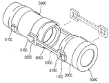
도 10 내지 도 12는 본 발명의 제3 실시예에 따른 원터치식 배관 연결장치를 도시한 도면.
도 13는 본 발명의 제3 실시예에 따른 원터치식 배관 연결장치 중 고정부재의 설치상태를 도시한 사시도.
도 14 및 도 15는 본 발명의 제4 실시예에 따른 원터치식 배관 연결장치를 도시한 도면.
도 16 및 도 17은 본 발명의 제5 실시예에 따른 원터치식 배관 연결장치를 도시한 도면.
도 18 및 도 19은 본 발명의 제3 내지 제5 실시예에 따른 원터치식 배관 연결장치에 적용가능한 보호캡의 설치상태를 도시한 도면.
상기 목적을 달성하기 위하여, 본 발명은, 배관이 삽입가능한 크기를 갖고 상기 배관 삽입방향으로 직경이 점차 증가함에 따라 경사면을 갖도록 중앙부에 형성되는 삽입홀과, 상기 삽입홀과 연통되는 관통공이 형성되고 그 삽입홀의 직경이 감소되는 부분의 일측면으로부터 연장되는 원형리브가 구비되되, 상기 삽입홀 및 관통공 사이에는 걸림턱이 형성되고, 상기 원형리브 내측면에는 나선이 형성되며, 둘레를 따라 수평방향으로 볼트 및 너트의 결합을 위한 복수개의 체결홀이 형성되는 압륜부재와; 상기 원형리브 내측면과 외주면이 나선결합됨에 따라 일측면이 상기 걸림턱과 밀착되는 안착부와, 상기 안착부로부터 상기 원형리브 외측으로 연장되고 내측면에 경사홈이 형성되며 일측면이 상기 원형리브 외측면과 접촉되는 경사부와, 상기 경사부로부터 연장되고 상기 안착부보다 더 큰 직경을 가지며 끝단에 이탈방지링의 설치를 위한 고정홈이 형성된 수평부로 이루어진 가이드부재와; 상기 배관이 삽입가능하게 천공된 형상으로 상기 가이드부재에 수평하게 삽입되되, 상기 경사부에 위치되는 부분의 외주면을 따라 형성된 복수개의 단턱홀과, 상기 수평부 및 경사부의 타측면과 함께 가압스프링의 배치를 위한 밀폐공간을 형성하고 상기 고정홈에 설치된 상기 이탈방지링과의 접촉에 의해 외부로의 노출이 방지되는 제1 돌출리브와, 상기 제1 돌출리브에 대향되도록 형성되어 그 제1 돌출리브와의 사이에 상기 이탈방지링의 설치공간을 마련하고 상기 이탈방지링이 외부로 분리되는 것을 방지하는 제2 돌출리브가 구비된 지지부재와; 상기 지지부재의 단턱홀에 삽입되는 톱니부와 상기 톱니부로부터 연장되어 상기 단턱홀의 단턱에 배치되는 돌출편으로 이루어져, 상기 배관이 상기 압륜부재에 배치될 경우 상기 가압스프링의 복원력에 의해 상기 경사홈에 상기 돌출편이 밀착되면서 상기 톱니부의 톱니가 상기 배관의 외주면에 수평하게 밀착되는 밀착부재와; 상기 압륜부재의 삽입홀 경사면을 따라 밀착되도록 테이퍼링 처리된 고무패킹;으로 구성되는 것을 특징으로 한다.
이하, 도면을 참조로 하여 본 발명에 따른 원터치식 배관 연결장치를 설명하기로 한다.
도 1 내지 도 3은 본 발명의 제1 실시예에 따른 원터치식 배관 연결장치를 도시한 도면이다.
본 발명에 따른 원터치식 배관 연결장치는 기본적으로 배관(10)이 삽입가능하고 경사면을 갖는 삽입홀(101)과 직경이 감소된 삽입홀(101)측의 외측면에 원형리브(110)가 구비된 압륜부재(100)와, 원형리브(110)와 나선결합되는 가이드부재(200)와, 경사홈(221)이 형성된 가이드부재(200) 내측에 배치되고 가압스프링(50)의 배치를 위한 공간을 형성하는 지지부재(300)와, 지지부재(300)에 관통설치되어 경사홈(221)에 배치됨에 따라 가압스프링(50)의 복원력에 의해 배관(10)과 밀착되는 밀착부재(400)와, 압륜부재(100)의 삽입홀(101) 경사면과 밀착되도록 테이퍼링 처리된 면을 갖는 고무패킹(500)으로 구성된다.
상기 압륜부재(100)는 종래의 배관(10)이 삽입가능한 크기를 갖고 배관(10) 삽입방향으로 직경이 점차 증가함에 따라 경사면을 갖도록 중앙부에 형성되는 삽입홀(101)과, 삽입홀(101)과 연통되는 관통공(111)이 형성되고 그 삽입홀(101)의 직경이 감소되는 부분의 일측면으로부터 연장되는 원형리브(110)가 구비됨과 더불어, 삽입홀(101) 및 관통공(111) 사이에는 걸림턱(120)이 형성되어 있어 이하 기술되는 가이드부재(200)의 이동범위가 그 걸림턱(120)에 의해 제한되고, 원형리브(110) 내측면에는 가이드부재(200)와 결합되기 위한 나선이 형성되며, 둘레를 따라서는 수평방향으로 볼트(20) 및 너트(30)의 결합을 위한 복수개의 체결홀(102)이 형성된 구조를 갖는다.
여기서 상기 압륜부재(100)는 등록발명 1 및 2에 기재된 바와 같이 고무패킹(500)을 사이에 두고 종래의 플랜지와 볼트(20) 및 너트(30)로 결합되거나, 관체간의 연결을 위해 고무패킹(500)을 사이에 두고 그 관체 각각에 설치될 수 있다.
상기 가이드부재(200)는 나선 형성된 원형리브(110) 내측면과 외주면이 나선결합됨에 따라 일측면이 걸림턱(120)과 밀착되는 안착부(210)와, 안착부(210)로부터 원형리브(110) 외측으로 연장되고 내측면에 경사홈(221)이 형성되며 일측면이 원형리브(110) 외측면과 접촉되는 경사부(220)와, 경사부(220)로부터 연장되고 안착부(210)보다 더 큰 직경을 가지며 끝단에 이탈방지링(40)의 설치를 위한 고정홈(231)이 형성된 수평부(230)로 이루어지는데, 이와 같은 구조에 따르면 압륜부재(100) 및 가이드부재(200)간의 연결이 원형리브(110) 및 안착부(210)의 결합에 의해 이루어진 상태에서 경사부(220)의 경사홈(221)에 이하 상세히 기술되는 밀착부재(400)가 배치되고 수평부(230)에 가압스프링(50) 및 이탈방지링(40)이 배치된다.
상기 지지부재(300)는 배관(10)이 삽입가능하게 천공된 형상으로 가이드부재(200)에 수평하게 삽입되는데, 이는 경사부(220)에 위치되는 부분의 외주면을 따라 형성된 복수개의 단턱홀(301)과, 수평부(230) 및 경사부(220)의 타측면과 함께 가압스프링(50)의 배치를 위한 밀폐공간을 형성하고 고정홈(231)에 설치된 이탈방지링(40)과의 접촉에 의해 외부로의 노출이 방지되는 제1 돌출리브(310)와, 제1 돌출리브(310)에 대향되도록 형성되어 그 제1 돌출리브(310)와의 사이에 이탈방지링(40)의 설치공간을 마련하고 이탈방지링(40)이 외부로 분리되는 것을 방지하는 제2 돌출리브(320)가 구비된 구조를 갖는다.
상기의 지지부재(300) 구조에 따르면, 이 지지부재(300)를 가이드부재(200)로 삽입할 경우 단턱홀(301)에 배치된 밀착부재(400)의 일부(이하 기술되는 '톱니부' 전체)가 단턱홀(301) 및 지지부재(300)의 내측공간으로 위치될 수 있음에 따라 경사홈(221)까지 도달하게 되고, 가압스프링(50)에 의해 가이드부재(200)로의 지지부재(300) 삽입이 제한되는 한편, 지지부재(300)를 압륜부재(100)측으로 압박한 상태에서 배관(10)을 지지부재(300)로부터 압륜부재(100)까지 통과시킨 다음으로 지지부재(300)의 압박을 해제하게 되면 그 가압스프링(50)의 복원력에 의해 지지부재(300)가 외측으로 밀려나면서 밀착부재(400)가 경사홈(221)을 따라 이동하게 되고 결과적으로 그 경사홈(221)에서 더 이상 이동할 수 없게 되는 동시에 배관(10)과 밀착되는 상태를 유지하게 된다.
한편으로 상기 이탈방지링(40)은 지지부재(300)가 가이드부재(200)로부터 분리되지 않도록 하기 위한 것으로 제1 및 제2 돌출리브(310, 320) 사이에 마련된 공간을 통해 설치되는데, 다시 말해서 제1 돌출리브(310)가 가이드부재(200) 내측에 위치되고 제2 돌출리브(320)가 외부로 노출되도록 한 다음 그 사이의 공간을 활용해 가이드부재(200)의 고정홈(231)을 따라 이탈방지링(40)이 설치되도록 한다.
여기서 상기 이탈방지링(40)을 보다 용이하게 설치하기 위한 구조를 살펴보면, 일부가 절삭되고 고정홈(231)에 설치되는 링부(41)와 그 링부(41)의 절삭된 부분 끝단에 구비되는 노출편(42)으로 이탈방지링(40)이 이루어지도록 하고, 가이드부재(200) 끝단, 즉 수평부(230) 끝단에 고정홈(231)과 연통되는 개방부(201)를 형성하여 그 개방부(201)를 통해 노출편(42)이 외부로 돌출가능하도록 함으로써 개방부(201)에서 한 쌍의 노출편(42) 겹쳐지도록 링부(41)를 구부린 다음 외력을 제거하게 되면 고정홈(231)에 링부(41)가 손쉽게 설치될 수 있다.
또한 본 발명의 배관 연결장치가 지중에 매설될 시에 노출편(42)이 불필요하게 토사에 의해 압박되어 링부(41)가 유동될 수 있음에 따라 이를 방지하기 위해, 링부(41) 및 노출편(42)의 연결부분에 절단선을 형성하여 고정홈(231)에 링부(41)가 설치된 다음 노출편(42)을 용이하게 제거할 수 있다.
상기 밀착부재(400)는 지지부재(300)의 단턱홀(301)에 삽입되는 톱니부(410)와 톱니부(410)로부터 연장되어 단턱홀(301)의 단턱에 배치되는 돌출편(420)으로 이루어져, 배관(10)이 압륜부재(100)에 배치될 경우 가압스프링(50)의 복원력에 의해 경사홈(221)에 돌출편(420)이 밀착되면서 톱니부(410)의 톱니가 배관(10)의 외주면에 수평하게 밀착되는 것으로, 톱니 전체가 배관(10)에 밀착되도록 그 밀착부재(400) 및 경사홈(221)의 형상이 도면과 같이 고려되는 것이 바람직하다.
또한 상기 밀착부재(400)의 톱니부(410)에는 도 4에서와 같이 체결스프링(710)과 체결스프링(710) 양단에 고정되는 연결핀(720)으로 이루어진 고정편(700)이 수평방향으로 관통설치되도록 하고 그 고정편(700)의 연결핀(720)이 단턱홀(301)의 양측면에 형성된 핀홀(301a)에 설치되도록 하여 밀착부재(400)가 단턱홀(301)로부터 이탈되지 않도록 할 수 있음에 따라, 지지부재(300)를 가이드부재(200)에 설치할 시에 밀착부재(400)가 단턱홀(301)에서 분리되는 현상을 방지할 수 있음과 함께 체결스프링(710)이 갖는 연성에 의해 밀착부재(400)의 톱니부(410)가 배관(10)에 고정되거나 돌출편(420)이 경사홈(221)에 밀착되는 데에는 무리가 따르지 않게 된다.
상기 고무패킹(500)은 도 5에서와 같이 압륜부재(100)의 삽입홀(101) 경사면을 따라 밀착되도록 일측 또는 양측이 테이퍼링 처리된 구조를 갖고, 등록특허 1 및 2에 기재된 바와 같이 압륜부재(100) 및 종래 플랜지간의 결합이나 압륜부재(100)간의 볼트(20) 및 너트(30)의 결합을 통해 압착됨에 따라 관체간의 연결에서 수밀성을 보장하게 된다.
추가적으로 상기 안착부(210) 내측에 형성된 단턱면(211)에 배치되는 몸통부(610)와 몸통부(610)로부터 내측으로 연장되는 탄성편(620)과 몸통부(610) 끝단으로부터 외측으로 수직하게 연장되어 안착부(210) 및 걸림턱(120) 사이에 배치되는 개재부(630)로 이루어져, 압륜부재(100)측으로의 배관(10) 이동방향에 대응하여 탄성편(620)이 삽입홀(101)측으로 이동되면서 그 배관(10)의 외주면을 따라 밀착되는 수밀부재(600)를 통해 보다 우수한 수밀성을 제공할 수도 있다.
여기서 상기 수밀부재(600)는 그 재질을 고무와 같은 탄성체로 하여 안착부(210) 및 걸림턱(120)에 의해 개재부(630)가 압박됨에 따라 그 수밀부재(600)의 견고한 고정 상태가 유지된다.
도 6 내지 도 9는 본 발명의 제2 실시예에 따른 따른 원터치식 배관 연결장치를 도시한 도면이다.
본 발명의 제2 실시예에 따른 원터치식 배관 연결장치는 압륜부재(100)를 대신하여 사용되는 원통형부재(800)와, 원통형부재(800)와 나선결합되는 가이드부재(200)와, 경사홈(221)이 형성된 가이드부재(200) 내측에 배치되고 가압스프링(50)의 배치를 위한 공간을 형성하는 지지부재(300)와, 지지부재(300)에 관통설치되어 경사홈(221)에 배치됨에 따라 가압스프링(50)의 복원력에 의해 배관(10)과 밀착되는 밀착부재(400)로 구성된다.
참고로 원통형부재(800)와 연결되는 하기의 가이드부재(200), 지지부재(300) 및 밀착부재(400)는 그 구조와 기능이 이전에 기술된 본 발명의 배관 연결장치와 동일한 이유로 이의 구체적인 동작에 대한 언급은 생략하기로 한다.
상기 원통형부재(800)는 배관(10)이 삽입가능한 크기를 갖고 내측면에 나선이 형성된 것으로, 가이드부재(200), 지지부재(300) 및 밀착부재(400)가 일조를 이루어 그 원통형부재(800)를 사이에 두고 한 쌍의 배관(10) 각각에 설치됨에 따라 그 배관(10)을 연결시키게 된다.
또한 상기 원통형부재(800)는 그 내주면 중심부를 따라서 원통형부재(800) 양측으로 삽입되는 한 쌍의 배관(10)의 길이를 제한하기 위한 삽입한정리브(810)를 구비함에 따라, 직관, 곡관 등을 포함하는 배관(10)이 동일한 길이만큼 원통형부재(800)에 삽입될 수 있다.
상기 가이드부재(200)는 원통형부재(800) 내측면과 외주면이 나선결합되는 안착부(210)와, 안착부(210)로부터 원통형부재(800) 외측으로 연장되고 내측면에 경사홈(221)이 형성되며 일측면이 원통형부재(800) 외측면과 접촉되는 경사부(220)와, 경사부(220)로부터 연장되고 안착부(210)보다 더 큰 직경을 가지며 끝단에 이탈방지링(40)의 설치를 위한 고정홈(231)이 형성된 수평부(230)로 이루어진다.
여기서 본 발명의 제1 실시예에서 사용된 수밀부재(600)가 가이드부재(200)에 설치될 수 있으며, 원통형부재(800) 및 가이드부재(200)가 결합됨에 따라 수밀부재(600)의 개재부(630)가 안착부(210) 일측면과 삽입한정리브(810)에 의해 밀착고정될 수 있다.
상기 지지부재(300)는 배관(10)이 삽입가능하게 천공된 형상으로 가이드부재(200)에 수평하게 삽입되되, 경사부(220)에 위치되는 부분의 외주면을 따라 형성된 복수개의 단턱홀(301)과, 수평부(230) 및 경사부(220)의 타측면과 함께 가압스프링(50)의 배치를 위한 밀폐공간을 형성하고 고정홈(231)에 설치된 이탈방지링(40)과의 접촉에 의해 외부로의 노출이 방지되는 제1 돌출리브(310)와, 제1 돌출리브(310)에 대향되도록 형성되어 그 제1 돌출리브(310)와의 사이에 이탈방지링(40)의 설치공간을 마련하고 이탈방지링(40)이 외부로 분리되는 것을 방지하는 제2 돌출리브(320)가 구비된 구조를 갖는다.
상기 밀착부재(400)는 지지부재(300)의 단턱홀(301)에 삽입되는 톱니부(410)와 톱니부(410)로부터 연장되어 단턱홀(301)의 단턱에 배치되는 돌출편(420)으로 이루어져, 배관(10)이 원통형부재(800)에 배치될 경우 가압스프링(50)의 복원력에 의해 경사홈(221)에 돌출편(420)이 밀착되면서 톱니부(410)의 톱니가 배관(10)의 외주면에 수평하게 밀착되도록 한다.
도 10 내지 도 12는 본 발명의 제3 실시예에 따른 원터치식 배관 연결장치를 도시한 도면이다.
본 발명에 따른 원터치식 배관 연결장치의 제3 실시예는 기본적으로 배관(10C)이 삽입가능한 크기를 갖고 외주면에는 제1 걸고리(110C)가 구비되는 체결부재(100C)와, 체결부재(100C)와 결합되는 가이드부재(200C)와, 경사홈(221C)이 형성된 가이드부재(200C) 내측에 배치되고 가압스프링(30C)의 배치를 위한 공간을 형성하는 지지부재(300C)와, 지지부재(300C)에 관통설치되어 경사홈(221C)에 배치됨에 따라 가압스프링(30C)의 복원력에 의해 배관(10C)과 밀착되는 밀착부재(400C)와, 체결부재(100C)에 관통설치되는 배관(10C)의 일측 끝단이 삽입되고 양측 외주면에 제2 걸고리(510C)가 구비되는 연결부재(500C)와, 일직하게 배치되는 제1 및 제2 걸고리(110C, 510C) 각각을 연결하여 배관(10C) 및 연결부재(500C)가 충격에 의해 일정범위 내에서 이동가능하게 하는 연결막대(600C)로 구성된다.
상기 체결부재(100C)는 배관(10C)이 삽입가능한 크기를 갖고 내측면에 나선이 형성되어져, 가이드부재(200C)와 나선결합되고 지지부재(300C) 및 밀착부재(400C)와 일조를 이루어 배관(10C)에 고정됨에 따라, 연결부재(500C)를 사이에 일직하게 배치되는 2개의 배관 각각에 설치되어 배관을 연결시키게 되는 한편, 외주면에 가이드부재(200C)를 향해 'ㄱ'자형으로 절곡되어져 구비되는 제1 걸고리(110C)와 연결부재(500C)에 구비된 제2 걸고리(510C)를 연결하는 연결막대(600C)를 통해서 지진과 같은 강한 충격이 발생할 경우 배관(10C)이 유동되도록 하여 이의 파손을 방지하게 된다.
상기 가이드부재(200C)는 체결부재(100C) 내측면과 외주면이 나선결합되는 안착부(210C)와, 안착부(210C)로부터 체결부재(100C) 외측으로 연장되고 내측면에 경사홈(221C)이 형성되며 일측면이 체결부재(100C) 외측면과 접촉되는 경사부(220C)와, 경사부(220C)로부터 연장되고 안착부(210C)보다 더 큰 직경을 가지며 끝단에 이탈방지링(20C)의 설치를 위한 고정홈(231C)이 형성된 수평부(230C)로 이루어지는데, 이와 같은 구조에 따르면 체결부재(100C) 및 가이드부재(200C)간에 나선결합된 상태에서 경사부(220C)의 경사홈(221C)에 밀착부재(400C)가 배치되고 수평부(230C)에 이탈방지링(20C) 및 가압스프링(30C)이 배치될 수 있다.
상기 지지부재(300C)는 배관(10C)이 삽입가능하게 천공된 형상으로 가이드부재(200C)에 수평하게 삽입되는데, 이는 경사부(220C)에 위치되는 부분의 외주면을 따라 형성된 복수개의 단턱홀(301C)과, 수평부(230C) 및 경사부(220C)의 타측면과 함께 가압스프링(30C)의 배치를 위한 밀폐공간을 형성하고 고정홈(231C)에 설치된 이탈방지링(20C)과의 접촉에 의해 외부로의 노출이 방지되는 제1 돌출리브(310C)와, 제1 돌출리브(310C)에 대향되도록 형성되어 그 제1 돌출리브(310C)와의 사이에 이탈방지링(20C)의 설치공간을 마련하고 이탈방지링(20C)이 외부로 분리되는 것을 방지하는 제2 돌출리브(320C)가 구비된 구조를 갖는다.
상기의 지지부재(300C) 구조에 따르면, 이 지지부재(300C)를 가이드부재(200C)로 삽입할 경우 단턱홀(301C)에 배치된 밀착부재(400C)의 일부(이하 기술되는 '톱니부' 전체)가 단턱홀(301C) 및 지지부재(300C)의 내측공간으로 위치될 수 있음에 따라 경사홈(221C)까지 도달하게 되고, 가압스프링(30C)에 의해 가이드부재(200C)로의 지지부재(300C) 삽입이 제한되는 한편, 지지부재(300C)를 체결부재(100C)측으로 압박한 상태에서 배관(10C)을 지지부재(300C)로부터 압륜부재(100C)까지 통과시킨 다음으로 지지부재(300C)의 압박을 해제하게 되면 그 가압스프링(30C)의 복원력에 의해 지지부재(300C)가 외측으로 밀려나면서 밀착부재(400C)가 경사홈(221C)을 따라 이동하게 되고 결과적으로 그 경사홈(221C)에서 더 이상 이동할 수 없게 되는 동시에 배관(10C)과 밀착되는 상태를 유지하게 된다.
한편으로 상기 이탈방지링(20C)은 지지부재(300C)가 가이드부재(200C)로부터 분리되지 않도록 하기 위한 것으로 제1 및 제2 돌출리브(310C, 320C) 사이에 마련된 공간을 통해 설치되는데, 다시 말해서 제1 돌출리브(310C)가 가이드부재(200C) 내측에 위치되고 제2 돌출리브(320C)가 외부로 노출되도록 한 다음 그 사이의 공간을 활용해 가이드부재(200C)의 고정홈(231C)을 따라 이탈방지링(20C)이 설치되도록 한다.
여기서 상기 이탈방지링(20C)은 일부가 절삭되어져 있어 외력으로 이를 구부린 다음 고정홈(231C)에 위치시킨 상태에서 그 외력을 제거함으로써 고정홈(231C)에 설치된다.
상기 밀착부재(400C)는 지지부재(300C)의 단턱홀(301C)에 삽입되는 톱니부(410C)와 톱니부(410C)로부터 연장되어 단턱홀(301C)의 단턱에 배치되는 돌출편(420C)으로 이루어져, 배관(10C)이 압륜부재(100C)에 배치될 경우 가압스프링(30C)의 복원력에 의해 경사홈(221C)에 돌출편(420C)이 밀착되면서 톱니부(410C)의 톱니가 배관(10C)의 외주면에 수평하게 밀착되는 것으로, 톱니 전체가 배관(10C)에 밀착되도록 그 밀착부재(400C) 및 경사홈(221C)의 형상이 도면과 같이 고려되는 것이 바람직하다.
상기 연결부재(500C)는 지지부재(300C)에 관통설치되는 배관(10C)의 일측 끝단이 삽입되고, 양측 내주면 및 배관(10C) 사이에 링형 고무패킹(40C)을 개재시키기 위한 절삭홈(501C)이 형성되며, 양측 외주면에 대향되도록 'ㄱ'자 형상으로 절곡되는 제2 걸고리(510C)가 구비된 구조를 갖는데, 이에 따르면 체결부재(100C), 가이드부재(200C), 지지부재(300C) 및 밀착부재(400C)가 배관(10C)에 고정된 상태에서 그 배관(10C) 끝단을 연결부재(500C) 내측(바람직하게는 내측 중앙부)에 위치시키고 체결부재(100C) 및 연결부재(500C)에 구비된 제1 및 제2 걸고리(110C, 510C)에 연결막대(600C)를 설치함으로써 지하에 매설되는 배관(10C)이 평상시에는 움직이지 않다가 지진과 같은 큰 충격이 가해질 시에는 연결부재(500C) 및 연결막대(600C)의 크기에 대응하여 그 연결부재(500C)로부터 이탈되지 않으며 일정범위 내에서 이동가능하게 된다.
참고로 상기 연결부재(500C)는 그 전체적인 형상이 도면에 도시된 직관 형태에 한정되지 않고 곡관, T형관 형상 등을 가질 수 있으며, 이에 따라 배관을 직선, 곡선, 직각방향 등으로 자유롭게 연결할 수 있다.
상기 연결막대(600C)는 일직하게 배치되는 제1 및 제2 걸고리(110C, 510C) 각각에 체결되는 제1 및 제2 결합링(610, 620C)과, 제1 및 제2 결합링(610C, 620C)을 연결하는 몸체부(630C)로 이루어져, 체결부재(100C), 가이드부재(200C), 지지부재(300C) 및 밀착부재(400C)를 통해 제1 및 제2 걸고리(110C, 510C)가 상호간에 최대한 이격되도록 연결막대(600C)를 설치하여 체결부재(100C)와 연결부재(500C)를 연결함으로써 본 발명의 배관연결 장치가 내진성을 갖도록 기능하며, 제1 및 제2 결합링(610C, 620C)의 크기에 따라 충격에 의한 배관(10C)의 이동범위가 늘어나거나 줄어들 수 있다.
도 13은 본 발명에 따른 원터치식 배관 연결장치 중 고정부재의 설치상태를 도시한 도면이다.
또한 상기 체결부재(100C)를 향해 연결부재(500C)에 삽입되는 배관의 외주면을 1/2씩 둘러싸고, 끝단에 연결막대(600C)의 제2 결합링(620C)과 체결되는 제3 걸고리(710C)가 구비된 한 쌍의 고정부재(700C)를 연결부재(500C) 기준으로 체결부재(100C)와 대향 배치하여 사용할 수도 있는데, 연결부재(500C)를 사이에 두고 2개 배관을 연결하는 과정에서 일측 배관에는 체결부재(100C), 가이드부재(200C), 지지부재(300C) 및 밀착부재(400C)를 설치하고 타측 배관에는 그 고정부재(700C)를 사용함으로써 비용절감을 도모할 수 있으며, 다른 한편으로 끝단 직경이 다른 부분보다 큰 1개 배관에 대해서 체결부재(100C), 가이드부재(200C), 지지부재(300C)를 삽입하기 어려운 문제점이 있으나, 고정부재(700C)는 배관에 삽입할 필요가 없는 분리형임에 따라 배관 끝단 직경에 구애받지 않으며 설치할 수 있다.
또한 본 발명의 배관 연결장치의 경우 그 재질을 금속이나 플라스틱으로 하기 때문에 제1 및 제2 걸고리(110C, 510C) 및 제3 걸고리(710C)가 탄성력에 의해 제1 및 제2 결합링(610C, 620C)과 체결되거나 분리가능한 형상을 갖도록 하여 도면에서와 같이 제1 및 제2 결합링(610C, 620C)이 제1 내지 제3 걸고리(110C, 510C, 710C)에 걸려있는 상태에서는 이탈되지 않도록 하다가 외력으로 각 걸고리 끝단을 잡아당길 시에는 제1 및 제2 결합링(610C, 620C)의 분리가 가능해진다.
참고로 상기 제1 및 제2 걸고리(110C, 510C)가 구비되는 체결부재(100C) 및 연결부재(500C)의 외주면이 다각기둥 형상을 갖도록 하여 체결부재(100C)나 연결부재(500C)의 회전을 용이하게 하도록 함과 동시에 그 다각기둥 형상의 평면상에 제1 및 제2 걸고리(110C, 510C)가 구비되도록 하여 제1 및 제2 걸고리(110C, 510C)의 하부가 고정되는 면적이 안정적으로 균일하게 할 수 있으며, 제1 및 제2 걸고리(110C, 510C)가 구비되는 고무패킹(40C)이 설치되는 연결부재(500C) 외주면이 볼록한 형상을 갖도록 하고 이에 대응하는 내주면에 홈이 형성되도록 할 수도 있다.
도 14 및 도 15는 본 발명의 제4 실시예에 따른 원터치식 배관 연결장치를 도시한 도면이다.
본 발명에 따른 원터치식 배관 연결장치의 제4 실시예는 배관(10C)이 삽입가능한 크기를 갖고 내측면에는 나선이 형성되며 외주면에는 제1 결합리브(110-1C)가 구비되는 체결부재(100-1C)와, 체결부재(100-1C)와 나선결합되는 가이드부재(200C)와, 경사홈(221C)이 형성된 가이드부재(200C) 내측에 배치되고 가압스프링(30C)의 배치를 위한 공간을 형성하는 지지부재(300C)와, 지지부재(300C)에 관통설치되어 경사홈(221C)에 배치됨에 따라 가압스프링(30C)의 복원력에 의해 배관(10C)과 밀착되는 밀착부재(400C)와, 체결부재(100-1C)에 관통설치되는 배관(10C)의 일측 끝단이 삽입되고 양측 외주면에 제2 결합리브(510-1C)가 구비되는 연결부재(500-1C)와, 제1 및 제2 결합리브(110-1C, 510-1C)를 연결시키고 충격에 의해 일측이 이동가능한 연결볼트(600-1C)로 구성된다.
참고로 상기 체결부재(100C)와 연결되는 제2 실시예의 가이드부재(200C), 지지부재(300C) 및 밀착부재(400C)는 그 구조와 기능이 이전에 기술된 사항과 동일한 이유로 이의 구체적인 언급은 생략하기로 한다.
상기 체결부재(100-1C)는 배관(10C)이 삽입가능한 크기를 갖고 내측면에는 나선이 형성되는 한편, 외주면에는 수평방향으로 나선홀(111-1C)이 형성된 제1 결합리브(110-1C)가 구비되어, 제1 결합리브(110-1C)의 나선홀(111-1C)과 연결볼트(600-1C)의 일측이 나선결합됨으로써 체결부재(100-1C)와 연결부재(500-1C)간의 연결이 이루어진다.
상기 연결부재(500-1C)는 지지부재(300C)에 관통설치되는 배관(10C)의 일측 끝단이 삽입되고, 양측 내주면 및 배관(10C) 사이에 링형 고무패킹(40C)을 개재시키기 위한 절삭홈(501C)이 형성되며, 양측 외주면에 수평방향으로 나선홀(111-1C)보다 더 큰 직경을 갖는 관통공(511-1C)이 형성된 제2 결합리브(510-1C)가 구비된 구조를 통해 체결부재(100-1C)와 연결볼트(600-1C)로 연결되어 관통공(511-1C) 내측에서 연결볼트(600-1C)가 일정범위 내에서 이동될 수 있음에 따라, 연결부재(500-1C) 내측에 대향 배치되는 2개의 배관과 함께 충격에 의해 그 일정범위만큼 이동가능하게 된다.
상기 연결볼트(600-1C)는 일직하게 배치되는 제1 및 제2 결합리브(110-1C, 510-1C)에서 관통공(511-1C)을 통과하여 나선홀(111-1C)에 결합되는 몸통부(610-1C)와, 몸통부(610-1C) 끝단에 구비되고 관통공(511-1C)보다 더 큰 직경을 갖는 헤드부(610-1C)로 이루어져, 제1 및 제2 결합리브(110-1C, 510-1C)에 결합된 상태에서 바람직하게는 볼 형상을 갖는 헤드부(610-1C)에 의해 이탈되지 않게 되고 몸통부(610-1C)가 관통공(511-1C)의 크기에 대응하여 유동될 수 있음에 따라 배관(10C)에 가해지는 충격을 완화시키게 된다.
도 16 및 도 17은 본 발명의 제5 실시예에 따른 원터치식 배관 연결장치를 도시한 도면이다.
본 발명에 따른 원터치식 배관 연결장치의 제5 실시예는 배관(10C)이 삽입가능한 크기를 갖고 내측면에는 나선이 형성되며 외주면에는 제3 결합리브(110-2C)가 구비되는 체결부재(100-2C)와, 체결부재(100-2C)와 나선결합되는 가이드부재(200C)와, 경사홈(221C)이 형성된 가이드부재(200C) 내측에 배치되고 가압스프링(30C)의 배치를 위한 공간을 형성하는 지지부재(300C)와, 지지부재(300C)에 관통설치되어 경사홈(221C)에 배치됨에 따라 가압스프링(30C)의 복원력에 의해 배관(10C)과 밀착되는 밀착부재(400C)와, 체결부재(100-2C)에 관통설치되는 배관(10C)의 일측 끝단이 삽입되고 양측 외주면에 제4 결합리브(510-2C)가 구비되는 연결부재(500-2C)와, 제3 및 제4 결합리브(110-2C, 510-2C)를 연결시키고 충격에 의해 양측이 유동가능한 결합부재(600-2C)로 구성된다.
참고로 상기 체결부재(100-2C)와 연결되는 제3 실시예의 가이드부재(200C), 지지부재(300C) 및 밀착부재(400C)는 그 구조와 기능이 이전에 기술된 사항과 동일한 이유로 이의 구체적인 언급은 생략하기로 한다.
상기 체결부재(100-2C)는 배관(10C)이 삽입가능한 크기를 갖고 내측면에는 나선이 형성되며 외주면에는 수평방향으로 통공(111-2C)이 형성된 제3 결합리브(110-2C)가 구비된 구조를 통해 제3 결합리브(110-2C)의 통공(111-2C)에 결합부재(600-2C)의 일측이 고정되도록 하여 체결부재(100-2C)와 연결부재(500-2C)간의 연결이 이루어진다.
상기 연결부재(500-2C)는 지지부재(300C)에 관통설치되는 배관(10C)의 일측 끝단이 삽입되고, 양측 내주면 및 배관(10C) 사이에 링형 고무패킹(40C)을 개재시키기 위한 절삭홈(501C)이 형성되며, 양측 외주면에 수평방향으로 삽입공(511-2C)이 형성된 제4 결합리브(510-2C)가 구비된 구조에 의해, 결합부재(600-2C)가 제3 및 제4 결합리브(110-2C, 510-2C)에 유동가능하게 연결되어 본 발명의 배관 연결장치가 내진성을 갖도록 한다.
상기 결합부재(600-2C)는 일직하게 배치되는 제3 및 제4 결합리브(110-2C, 510-2C)에서 삽입공(511-2C) 및 통공(111-2C)을 통과하여 배치되고 통공(111-2C) 및 삽입공(511-2C)보다 작은 직경을 갖는 막대부(610-2C)와, 막대부(610-2C) 일측 끝단에 구비되고 삽입공(511-2C)보다 더 큰 직경을 갖는 머리부(620-2C)와, 막대부(610-2C) 타측 끝단에 나선결합되고 통공(111-2C)보다 더 큰 직경을 갖는 결합너트(630-2C)로 이루어짐으로써, 막대부(610-2C)가 제3 및 제4 결합리브(110-2C, 510-2C)로부터 이탈되지 않으면서 유동적으로 체결부재(100-2C) 및 연결부재(500-2C)를 연결시킴에 따라 연결부재(500-2C) 내측에 대향 배치되는 2개의 배관에 충격이 가해질 경우 일정범위 내에서 유동가능하게 된다.
여기서 본 발명의 제3 내지 제5 실시예의 연결부재(500C, 500-1C, 500-2C)는 그 양측으로 2개의 배관이 삽입되는 길이를 제한하기 위한 삽입한정리브(520C)를 구비함에 따라, 연결부재(500C) 측으로 대향 삽입되는 배관이 상호간에 동일한 길이만큼만 삽입될 수 있는 한편, 절삭홈(501C) 일측면에 돌기(502C)를 형성하고 고무패킹(40C)에 그 돌기가 끼움되는 요홈을 형성함으로써 그 고무패킹(40C)이 배관(10C) 및 절삭홈(501C) 사이의 공간에서 가급적 이동되지 않도록 할 수도 있다.
도 18 및 도 19는 본 발명의 원터치식 배관 연결장치 중 보호캡의 설치상태를 도시한 도면이다.
추가적으로 본 발명의 제3 내지 제5 실시예에 기술된 가이드부재(200C) 및 지지부재(300C)간에는 배관(10C)에 삽입 및 설치된 상태에서 틈이 발생하게 되기 때문에, 그 틈으로 이물질이 유입될 수 있음에 따라 배관(10C)에 설치 후 이물질로 인해 본 발명의 연결장치 분리가 원활하지 않을 수 있는 이유로, 그 틈을 밀폐시키기 위한 보호캡(800C)이 더 설치될 수 있는데, 이러한 보호캡(800C)은 배관(10C)에 가장 먼저 삽입되고 그 다음으로 가이드부재(200C) 및 지지부재(300C)가 배관(10C)에 고정되도록 한 후에 언급된 바와 같은 틈을 밀폐시키도록 설치된다.
여기서 상기 보호캡(800C)은 단순히 가이드부재(200C) 외주면을 따라 끼움됨으로써 고정되거나 그 가이드부재(200C) 외주면과 나선결합되는 구조를 가질 수 있다.
본 발명에 따른 원터치식 배관 연결장치는 압륜부재에 가이드부재, 지지부재 및 밀착부재를 배치한 상태에서 배관을 그 압륜부재측으로 삽입할 시에 가압스프링의 복원력에 의해 밀착부재가 가이드부재의 경사홈에 밀착되면서 그 배관의 외주면에 견고히 고정되는 구조에 따르므로 볼트를 사용하지 않고도 배관간의 연결을 간단히 수행할 수 있어 볼트의 풀림 현상에 의한 고정력 약화 현상이 발생되지 않는 한편, 고무패킹과 더불어 압륜부재 및 가이드부재 사이에 개재되는 수밀부재의 탄성편이 배관 둘레를 둘러싸는 구조를 통해 수밀성을 추가적으로 향상시킬 수 있다.
Claims (15)
- 배관(10)이 삽입가능한 크기를 갖고 상기 배관(10) 삽입방향으로 직경이 점차 증가함에 따라 경사면을 갖도록 중앙부에 형성되는 삽입홀(101)과, 상기 삽입홀(101)과 연통되는 관통공(111)이 형성되고 그 삽입홀(101)의 직경이 감소되는 부분의 일측면으로부터 연장되는 원형리브(110)가 구비되되, 상기 삽입홀(101) 및 관통공(111) 사이에는 걸림턱(120)이 형성되고, 상기 원형리브(110) 내측면에는 나선이 형성되며, 둘레를 따라 수평방향으로 볼트(20) 및 너트(30)의 결합을 위한 복수개의 체결홀(102)이 형성되는 압륜부재(100)와;상기 원형리브(110) 내측면과 외주면이 나선결합됨에 따라 일측면이 상기 걸림턱(120)과 밀착되는 안착부(210)와, 상기 안착부(210)로부터 상기 원형리브(110) 외측으로 연장되고 내측면에 경사홈(221)이 형성되며 일측면이 상기 원형리브(110) 외측면과 접촉되는 경사부(220)와, 상기 경사부(220)로부터 연장되고 상기 안착부(210)보다 더 큰 직경을 가지며 끝단에 이탈방지링(40)의 설치를 위한 고정홈(231)이 형성된 수평부(230)로 이루어진 가이드부재(200)와;상기 배관(10)이 삽입가능하게 천공된 형상으로 상기 가이드부재(200)에 수평하게 삽입되되, 상기 경사부(220)에 위치되는 부분의 외주면을 따라 형성된 복수개의 단턱홀(301)과, 상기 수평부(230) 및 경사부(220)의 타측면과 함께 가압스프링(50)의 배치를 위한 밀폐공간을 형성하고 상기 고정홈(231)에 설치된 상기 이탈방지링(40)과의 접촉에 의해 외부로의 노출이 방지되는 제1 돌출리브(310)와, 상기 제1 돌출리브(310)에 대향되도록 형성되어 그 제1 돌출리브(310)와의 사이에 상기 이탈방지링(40)의 설치공간을 마련하고 상기 이탈방지링(40)이 외부로 분리되는 것을 방지하는 제2 돌출리브(320)가 구비된 지지부재(300)와;상기 지지부재(300)의 단턱홀(301)에 삽입되는 톱니부(410)와 상기 톱니부(410)로부터 연장되어 상기 단턱홀(301)의 단턱에 배치되는 돌출편(420)으로 이루어져, 상기 배관(10)이 상기 압륜부재(100)에 배치될 경우 상기 가압스프링(50)의 복원력에 의해 상기 경사홈(221)에 상기 돌출편(420)이 밀착되면서 상기 톱니부(410)의 톱니가 상기 배관(10)의 외주면에 수평하게 밀착되는 밀착부재(400)와;상기 압륜부재(100)의 삽입홀(101) 경사면을 따라 밀착되도록 테이퍼링 처리된 고무패킹(500);으로 구성되는 것을 특징으로 하는 원터치식 배관 연결 장치.
- 배관(10)이 삽입가능한 크기를 갖고 내측면에는 나선이 형성된 원통형부재(800)와;상기 원통형부재(800) 내측면과 외주면이 나선결합되는 안착부(210)와, 상기 안착부(210)로부터 상기 원통형부재(800) 외측으로 연장되고 내측면에 경사홈(221)이 형성되며 일측면이 상기 원통형부재(800) 외측면과 접촉되는 경사부(220)와, 상기 경사부(220)로부터 연장되고 상기 안착부(210)보다 더 큰 직경을 가지며 끝단에 이탈방지링(40)의 설치를 위한 고정홈(231)이 형성된 수평부(230)로 이루어진 가이드부재(200)와;상기 배관(10)이 삽입가능하게 천공된 형상으로 상기 가이드부재(200)에 수평하게 삽입되되, 상기 경사부(220)에 위치되는 부분의 외주면을 따라 형성된 복수개의 단턱홀(301)과, 상기 수평부(230) 및 경사부(220)의 타측면과 함께 가압스프링(50)의 배치를 위한 밀폐공간을 형성하고 상기 고정홈(231)에 설치된 상기 이탈방지링(40)과의 접촉에 의해 외부로의 노출이 방지되는 제1 돌출리브(310)와, 상기 제1 돌출리브(310)에 대향되도록 형성되어 그 제1 돌출리브(310)와의 사이에 상기 이탈방지링(40)의 설치공간을 마련하고 상기 이탈방지링(40)이 외부로 분리되는 것을 방지하는 제2 돌출리브(320)가 구비된 지지부재(300)와;상기 지지부재(300)의 단턱홀(301)에 삽입되는 톱니부(410)와 상기 톱니부(410)로부터 연장되어 상기 단턱홀(301)의 단턱에 배치되는 돌출편(420)으로 이루어져, 상기 배관(10)이 상기 원통형부재(800)에 배치될 경우 상기 가압스프링(50)의 복원력에 의해 상기 경사홈(221)에 상기 돌출편(420)이 밀착되면서 상기 톱니부(410)의 톱니가 상기 배관(10)의 외주면에 수평하게 밀착되는 밀착부재(400);로 구성되는 것을 특징으로 하는 원터치식 배관 연결 장치.
- 청구항 1 또는 청구항 2에 있어서,상기 안착부(210) 내측에 형성된 단턱면(211)에 배치되는 몸통부(610)와 상기 몸통부(610)로부터 내측으로 연장되는 탄성편(620)과 상기 몸통부(610) 끝단으로부터 외측으로 수직하게 연장되어 상기 안착부(210) 일측면에 밀착되는 개재부(630)로 이루어져, 상기 배관(10) 이동방향에 대응하여 탄성편(620)이 이동되면서 그 배관(10)의 외주면을 따라 밀착되는 수밀부재(600)가 더 설치되는 것을 특징으로 하는 원터치식 배관 연결 장치.
- 청구항 1 또는 청구항 2에 있어서,상기 이탈방지링(40)은 일부가 절삭된 링부(41)와 상기 링부(41)의 절삭된 부분 끝단에 구비되는 노출편(42)으로 이루어져, 상기 고정홈(231)과 연통되도록 상기 가이드부재(200) 끝단에 형성된 개방부(201)로 상기 노출편(42)이 돌출되는 것을 특징으로 하는 원터치식 배관 연결 장치.
- 청구항 4에 있어서,상기 링부(41) 및 노출편(42)의 연결부분에는 상기 이탈방지링(40)이 고정홈(231)에 설치된 상태에서 상기 노출편(42)의 절단을 용이하게 하기 위한 절단선이 형성되는 것을 특징으로 하는 원터치식 배관 연결 장치.
- 청구항 1 또는 청구항 2에 있어서,상기 밀착부재(400)의 톱니부(410)에는 체결스프링(710)과 상기 체결스프링(710) 양단에 고정되는 연결핀(720)으로 이루어진 고정편(700)이 수평방향으로 관통설치되고, 상기 고정편(700)의 연결핀(720)은 상기 단턱홀(301)의 양측면에 형성된 핀홀(301a)에 설치되는 것을 특징으로 하는 원터치식 배관 연결 장치.
- 청구항 2에 있어서,상기 원통형부재(800)의 내주면 중심부를 따라서는 그 원통형부재(800) 양측으로 삽입되는 한 쌍의 상기 배관(10)의 길이를 제한하기 위한 삽입한정리브(810)가 설치되는 것을 특징으로 하는 원터치식 배관 연결 장치.
- 배관(10C)이 삽입가능한 크기를 갖고 내측면에는 나선이 형성되며 외주면에는 제1 걸고리(110C)가 구비되는 체결부재(100C)와;상기 체결부재(100C) 내측면과 외주면이 나선결합되는 안착부(210C)와, 상기 안착부(210C)로부터 체결부재(100C) 외측으로 연장되고 내측면에 경사홈(221C)이 형성되며 일측면이 체결부재(100C) 외측면과 접촉되는 경사부(220C)와, 상기 경사부(220C)로부터 연장되고 안착부(210C)보다 더 큰 직경을 가지며 끝단에 이탈방지링(20C)의 설치를 위한 고정홈(231C)이 형성된 수평부(230C)로 이루어진 가이드부재(200C)와;상기 배관(10C)이 삽입가능하게 천공된 형상으로 가이드부재(200C)에 수평하게 삽입되되, 상기 경사부(220C)에 위치되는 부분의 외주면을 따라 형성된 복수개의 단턱홀(301C)과, 상기 수평부(230C) 및 경사부(220C)의 타측면과 함께 가압스프링(30C)의 배치를 위한 밀폐공간을 형성하고 고정홈(231C)에 설치된 이탈방지링(20C)과의 접촉에 의해 외부로의 노출이 방지되는 제1 돌출리브(310C)와, 상기 제1 돌출리브(310C)에 대향되도록 형성되어 그 제1 돌출리브(310C)와의 사이에 이탈방지링(20C)의 설치공간을 마련하고 이탈방지링(20C)이 외부로 분리되는 것을 방지하는 제2 돌출리브(320C)가 구비된 지지부재(300C)와;상기 지지부재(300C)의 단턱홀(301C)에 삽입되는 톱니부(410C)와, 톱니부(410C)로부터 연장되어 단턱홀(301C)의 단턱에 배치되는 돌출편(420C)으로 이루어져, 상기 배관(10C)이 체결부재(100C)에 관통배치될 경우 가압스프링(30C)의 복원력에 의해 경사홈(221C)에 돌출편(420C)이 밀착되면서 톱니부(410C)의 톱니가 배관(10C)의 외주면에 수평하게 밀착되는 밀착부재(400C)와;상기 지지부재(300C)에 관통설치되는 배관(10C)의 일측 끝단이 삽입되고, 양측 내주면 및 배관(10C) 사이에 링형 고무패킹(40C)을 개재시키기 위한 절삭홈(501C)이 형성되며, 양측 외주면에 대향되도록 절곡되는 제2 걸고리(510C)가 구비되는 연결부재(500C)와;일직하게 배치되는 상기 제1 및 제2 걸고리(110C, 510C) 각각에 체결되는 제1 및 제2 결합링(610C, 620C)과, 상기 제1 및 제2 결합링(610C, 620C)을 연결하는 몸체부(630C)로 이루어지는 연결막대(600C);로 구성되는 것을 특징으로 하는 원터치식 배관 연결 장치.
- 배관(10C)이 삽입가능한 크기를 갖고 내측면에는 나선이 형성되며 외주면에는 수평방향으로 나선홀(111-1C)이 형성된 제1 결합리브(110-1C)가 구비되는 체결부재(100-1C)와;상기 체결부재(100C) 내측면과 외주면이 나선결합되는 안착부(210C)와, 상기 안착부(210C)로부터 체결부재(100C) 외측으로 연장되고 내측면에 경사홈(221C)이 형성되며 일측면이 체결부재(100C) 외측면과 접촉되는 경사부(220C)와, 상기 경사부(220C)로부터 연장되고 안착부(210C)보다 더 큰 직경을 가지며 끝단에 이탈방지링(20C)의 설치를 위한 고정홈(231C)이 형성된 수평부(230C)로 이루어진 가이드부재(200C)와;상기 배관(10C)이 삽입가능하게 천공된 형상으로 가이드부재(200C)에 수평하게 삽입되되, 상기 경사부(220C)에 위치되는 부분의 외주면을 따라 형성된 복수개의 단턱홀(301C)과, 상기 수평부(230C) 및 경사부(220C)의 타측면과 함께 가압스프링(30C)의 배치를 위한 밀폐공간을 형성하고 고정홈(231C)에 설치된 이탈방지링(20C)과의 접촉에 의해 외부로의 노출이 방지되는 제1 돌출리브(310C)와, 상기 제1 돌출리브(310C)에 대향되도록 형성되어 그 제1 돌출리브(310C)와의 사이에 이탈방지링(20C)의 설치공간을 마련하고 이탈방지링(20C)이 외부로 분리되는 것을 방지하는 제2 돌출리브(320C)가 구비된 지지부재(300C)와;상기 지지부재(300C)의 단턱홀(301C)에 삽입되는 톱니부(410C)와, 톱니부(410C)로부터 연장되어 단턱홀(301C)의 단턱에 배치되는 돌출편(420C)으로 이루어져, 상기 배관(10C)이 체결부재(100C)에 관통배치될 경우 가압스프링(30C)의 복원력에 의해 경사홈(221C)에 돌출편(420C)이 밀착되면서 톱니부(410C)의 톱니가 배관(10C)의 외주면에 수평하게 밀착되는 밀착부재(400C)와;상기 지지부재(300C)에 관통설치되는 배관(10C)의 일측 끝단이 삽입되고, 양측 내주면 및 배관(10C) 사이에 링형 고무패킹(40C)을 개재시키기 위한 절삭홈(501C)이 형성되며, 양측 외주면에 수평방향으로 나선홀(111-1C)보다 더 큰 직경을 갖는 관통공(511-1C)이 형성된 제2 결합리브(510-1C)가 구비되는 연결부재(500-1C)와;일직하게 배치되는 상기 제1 및 제2 결합리브(110-1C, 510-1C)에서 관통공(511-1C)을 통과하여 나선홀(111-1C)에 결합되는 몸통부(610-1C)와, 상기 몸통부(610-1C) 끝단에 구비되고 관통공(511-1C)보다 더 큰 직경을 갖는 헤드부(620-1C)로 이루어지는 연결볼트(600-1C);로 구성되는 것을 특징으로 하는 원터치식 배관 연결 장치.
- 배관(10C)이 삽입가능한 크기를 갖고 내측면에는 나선이 형성되며 외주면에는 수평방향으로 통공(111-2C)이 형성된 제3 결합리브(110-2C)가 구비되는 체결부재(100-2C)와;상기 체결부재(100C) 내측면과 외주면이 나선결합되는 안착부(210C)와, 상기 안착부(210C)로부터 체결부재(100C) 외측으로 연장되고 내측면에 경사홈(221C)이 형성되며 일측면이 체결부재(100C) 외측면과 접촉되는 경사부(220C)와, 상기 경사부(220C)로부터 연장되고 안착부(210C)보다 더 큰 직경을 가지며 끝단에 이탈방지링(20C)의 설치를 위한 고정홈(231C)이 형성된 수평부(230C)로 이루어진 가이드부재(200C)와;상기 배관(10C)이 삽입가능하게 천공된 형상으로 가이드부재(200C)에 수평하게 삽입되되, 상기 경사부(220C)에 위치되는 부분의 외주면을 따라 형성된 복수개의 단턱홀(301C)과, 상기 수평부(230C) 및 경사부(220C)의 타측면과 함께 가압스프링(30C)의 배치를 위한 밀폐공간을 형성하고 고정홈(231C)에 설치된 이탈방지링(20C)과의 접촉에 의해 외부로의 노출이 방지되는 제1 돌출리브(310C)와, 상기 제1 돌출리브(310C)에 대향되도록 형성되어 그 제1 돌출리브(310C)와의 사이에 이탈방지링(20C)의 설치공간을 마련하고 이탈방지링(20C)이 외부로 분리되는 것을 방지하는 제2 돌출리브(320C)가 구비된 지지부재(300C)와;상기 지지부재(300C)의 단턱홀(301C)에 삽입되는 톱니부(410C)와, 톱니부(410C)로부터 연장되어 단턱홀(301C)의 단턱에 배치되는 돌출편(420C)으로 이루어져, 상기 배관(10C)이 체결부재(100C)에 관통배치될 경우 가압스프링(30C)의 복원력에 의해 경사홈(221C)에 돌출편(420C)이 밀착되면서 톱니부(410C)의 톱니가 배관(10C)의 외주면에 수평하게 밀착되는 밀착부재(400C)와;상기 지지부재(300C)에 관통설치되는 배관(10C)의 일측 끝단이 삽입되고, 양측 내주면 및 배관(10C) 사이에 링형 고무패킹(40C)을 개재시키기 위한 절삭홈(501C)이 형성되며, 양측 외주면에 수평방향으로 삽입공(511-2C)이 형성된 제4 결합리브(510-2C)가 구비되는 연결부재(500-2C)와;일직하게 배치되는 상기 제3 및 제4 결합리브(110-2C, 510-2C)에서 삽입공(511-2C) 및 통공(111-2C)을 통과하여 배치되고 통공(111-2C) 및 삽입공(511-2C)보다 작은 직경을 갖는 막대부(610-2C)와, 상기 막대부(610-2C) 일측 끝단에 구비되고 삽입공(511-2C)보다 더 큰 직경을 갖는 머리부(620-2C)와, 상기 막대부(610-2C) 타측 끝단에 나선결합되고 통공(111-2C)보다 더 큰 직경을 갖는 결합너트(630-2C)로 이루어지는 결합부재(600-2C);로 구성되는 것을 특징으로 하는 원터치식 배관 연결 장치.
- 청구항 8 내지 청구항 10 중 어느 한 항에 있어서,상기 연결부재(500C, 500-1C, 500-2C)의 내주면에는 배관(10C)이 삽입되는 길이를 제한하기 위한 삽입한정리브(520C)가 설치되는 것을 특징으로 하는 원터치식 배관 연결 장치.
- 청구항 8 내지 청구항 10 중 어느 한 항에 있어서,상기 절삭홈(501C) 일측면에는 돌기(502C)가 형성되고, 상기 고무패킹(40C)에는 그 돌기가 끼움되는 요홈이 형성되는 것을 특징으로 하는 원터치식 배관 연결 장치.
- 청구항 8에 있어서,상기 제1 및 제2 걸고리(110C, 510C)는 탄성력에 의해 제1 및 제2 결합링(610C, 620C)과 체결되거나 분리가능한 형상을 갖는 것을 특징으로 하는 원터치식 배관 연결 장치.
- 청구항 8에 있어서,상기 연결부재(500C)를 기준으로 하여 체결부재(100C)와 대향 배치되되, 그 체결부재(100C)를 향해 연결부재(500C)에 삽입되는 배관의 외주면을 1/2씩 둘러싸며, 끝단에 연결막대(600C)의 제2 결합링(620C)과 체결되는 제3 걸고리(710C)가 구비된 한 쌍의 고정부재(700C)를 더 포함하는 것을 특징으로 하는 원터치식 배관 연결 장치.
- 청구항 8 내지 청구항 10 중 어느 한 항에 있어서,상기 배관(10C)에 삽입되어 가이드부재(200C) 및 지지부재(300C)간의 틈을 밀폐시키기 위한 보호캡(800C)이 더 설치되는 것을 특징으로 하는 원터치식 배관 연결 장치.
Priority Applications (1)
| Application Number | Priority Date | Filing Date | Title |
|---|---|---|---|
| CA2797176A CA2797176C (en) | 2010-02-18 | 2011-02-16 | One-touch pipe connection device |
Applications Claiming Priority (6)
| Application Number | Priority Date | Filing Date | Title |
|---|---|---|---|
| KR10-2010-0014809 | 2010-02-18 | ||
| KR20100014809 | 2010-02-18 | ||
| KR1020100040869A KR100977308B1 (ko) | 2010-02-18 | 2010-04-30 | 원터치식 배관 연결장치 |
| KR10-2010-0040869 | 2010-04-30 | ||
| KR1020100117715A KR101271168B1 (ko) | 2010-11-24 | 2010-11-24 | 내진용 원터치식 배관 연결장치 |
| KR10-2010-0117715 | 2010-11-24 |
Publications (2)
| Publication Number | Publication Date |
|---|---|
| WO2011102637A2 true WO2011102637A2 (ko) | 2011-08-25 |
| WO2011102637A3 WO2011102637A3 (ko) | 2011-12-15 |
Family
ID=44483460
Family Applications (1)
| Application Number | Title | Priority Date | Filing Date |
|---|---|---|---|
| PCT/KR2011/001016 Ceased WO2011102637A2 (ko) | 2010-02-18 | 2011-02-16 | 원터치식 배관 연결장치 |
Country Status (2)
| Country | Link |
|---|---|
| CA (1) | CA2797176C (ko) |
| WO (1) | WO2011102637A2 (ko) |
Cited By (10)
| Publication number | Priority date | Publication date | Assignee | Title |
|---|---|---|---|---|
| CN103282714A (zh) * | 2011-09-02 | 2013-09-04 | 沃泰有限公司 | 一键式配管连接装置 |
| CN103925439A (zh) * | 2012-12-27 | 2014-07-16 | 泰州乐金电子冷机有限公司 | 水管连接装置 |
| JP2016538513A (ja) * | 2013-10-24 | 2016-12-08 | スウエイジロク・カンパニー | 単動押し式接続導管継手 |
| US10458582B2 (en) | 2015-04-23 | 2019-10-29 | Swagelok Company | Single action push to connect conduit fitting with colleting |
| US10584820B2 (en) | 2010-10-15 | 2020-03-10 | Swagelok Company | Push to connect conduit fitting with ferrule |
| US10704722B2 (en) | 2015-04-23 | 2020-07-07 | Swagellok Company | Single action push to connect conduit fitting |
| CN114562623A (zh) * | 2022-01-28 | 2022-05-31 | 华能国际电力股份有限公司德州电厂 | 一种环保脱硫装置 |
| US11781688B2 (en) | 2019-04-01 | 2023-10-10 | Swagelok Company | Push to connect conduit fitting assemblies and arrangements |
| CN117469480A (zh) * | 2023-12-28 | 2024-01-30 | 烟台天兵工程机械有限公司 | 一种便于加工的管道连接件 |
| CN121408522A (zh) * | 2025-11-25 | 2026-01-27 | 山西八建集团有限公司 | 一种道路管道施工装置 |
Families Citing this family (2)
| Publication number | Priority date | Publication date | Assignee | Title |
|---|---|---|---|---|
| US20190137016A1 (en) * | 2017-11-08 | 2019-05-09 | Shanghai Sansheng Metal Products. Co. Ltd. | Connecting union joint with smart connection of easy-flowing pipe system |
| CN115727198A (zh) * | 2022-12-02 | 2023-03-03 | 湖南易正物联科技有限公司 | 一种消防工程施工用安装支架 |
Family Cites Families (5)
| Publication number | Priority date | Publication date | Assignee | Title |
|---|---|---|---|---|
| JPH09222189A (ja) * | 1996-02-16 | 1997-08-26 | Silver Ee L Kk | アルミニウム被覆樹脂管のフランジ連結具 |
| JPH10274373A (ja) * | 1997-03-28 | 1998-10-13 | Ntn Corp | 管継手 |
| JP3537088B2 (ja) * | 2000-09-29 | 2004-06-14 | 株式会社タブチ | 樹脂管の継手構造 |
| KR200440560Y1 (ko) * | 2007-03-16 | 2008-06-17 | 박규남 | 합성수지관 연결구 |
| KR100866907B1 (ko) * | 2008-07-25 | 2008-11-04 | 국제산업주식회사 | 기밀용 접합 연결구 |
-
2011
- 2011-02-16 CA CA2797176A patent/CA2797176C/en not_active Expired - Fee Related
- 2011-02-16 WO PCT/KR2011/001016 patent/WO2011102637A2/ko not_active Ceased
Cited By (16)
| Publication number | Priority date | Publication date | Assignee | Title |
|---|---|---|---|---|
| US11002395B2 (en) | 2010-10-15 | 2021-05-11 | Swagelok Company | Push to connect conduit fitting with ferrule |
| US10584820B2 (en) | 2010-10-15 | 2020-03-10 | Swagelok Company | Push to connect conduit fitting with ferrule |
| JP2013542378A (ja) * | 2011-09-02 | 2013-11-21 | ウォーター−テイク カンパニー, リミテッド | ワンタッチ式配管連結装置 |
| CN103282714A (zh) * | 2011-09-02 | 2013-09-04 | 沃泰有限公司 | 一键式配管连接装置 |
| CN103925439A (zh) * | 2012-12-27 | 2014-07-16 | 泰州乐金电子冷机有限公司 | 水管连接装置 |
| JP2016538513A (ja) * | 2013-10-24 | 2016-12-08 | スウエイジロク・カンパニー | 単動押し式接続導管継手 |
| US10619780B2 (en) | 2013-10-24 | 2020-04-14 | Swagelok Company | Single action push to connect conduit fitting |
| US10458582B2 (en) | 2015-04-23 | 2019-10-29 | Swagelok Company | Single action push to connect conduit fitting with colleting |
| US10704722B2 (en) | 2015-04-23 | 2020-07-07 | Swagellok Company | Single action push to connect conduit fitting |
| US11073234B2 (en) | 2015-04-23 | 2021-07-27 | Swagelok Company | Single action push to connect conduit fitting |
| US11781688B2 (en) | 2019-04-01 | 2023-10-10 | Swagelok Company | Push to connect conduit fitting assemblies and arrangements |
| US12435820B2 (en) | 2019-04-01 | 2025-10-07 | Swagelok Company | Push to connect conduit fitting assemblies and arrangements |
| CN114562623A (zh) * | 2022-01-28 | 2022-05-31 | 华能国际电力股份有限公司德州电厂 | 一种环保脱硫装置 |
| CN114562623B (zh) * | 2022-01-28 | 2024-04-19 | 华能国际电力股份有限公司德州电厂 | 一种环保脱硫装置 |
| CN117469480A (zh) * | 2023-12-28 | 2024-01-30 | 烟台天兵工程机械有限公司 | 一种便于加工的管道连接件 |
| CN121408522A (zh) * | 2025-11-25 | 2026-01-27 | 山西八建集团有限公司 | 一种道路管道施工装置 |
Also Published As
| Publication number | Publication date |
|---|---|
| WO2011102637A3 (ko) | 2011-12-15 |
| CA2797176C (en) | 2015-01-06 |
| CA2797176A1 (en) | 2011-08-25 |
Similar Documents
| Publication | Publication Date | Title |
|---|---|---|
| WO2011102637A2 (ko) | 원터치식 배관 연결장치 | |
| WO2013048039A2 (ko) | 배관연결구 어셈블리 및 이를 이용한 배관연결방법 | |
| KR0170795B1 (ko) | 관 접속용 조인트 | |
| CN1339093A (zh) | 蚌壳式连接系统和方法 | |
| KR100977308B1 (ko) | 원터치식 배관 연결장치 | |
| WO2020045749A1 (ko) | 체결 상태를 체크할 수 있는 파이프 커플링 | |
| WO2016108517A1 (ko) | 회전쐐기를 이용한 파이프 연결장치 | |
| WO2011034254A1 (en) | Spiral-type flexible pipe connector | |
| WO2014189317A1 (ko) | 호스밴드를 이용한 배관의 부분 보수장치 | |
| WO2017003023A1 (ko) | 파이프 연결장치 | |
| WO2019221495A1 (ko) | 관 연결 조립체 | |
| WO2013162150A1 (ko) | 결합돌기가 형성된 튜브체결구 | |
| WO2016064118A1 (ko) | 관 연결 소켓 | |
| WO2009145487A2 (ko) | 파이프용 연결물 | |
| WO2018186651A1 (ko) | 관 연결용 조인트 | |
| WO2016080581A1 (ko) | 삽입 고정식 파이프 연결장치 | |
| WO2017126813A1 (ko) | 파이프 연결 어셈블리 | |
| WO2019221439A1 (ko) | 관 연결 조립체 | |
| WO2019177229A1 (ko) | 무용접 조립식 배관 플랜지 연결구 | |
| ITRM970555A1 (it) | Giunto ad accoppiamento rapido per connettere un tubo flessibile di piccolo diametro interno ad un tubo metallico di un impianto frenante | |
| WO2014030829A1 (ko) | 압력관 연결용 이음관의 원터치 3단 체결장치 및 이를 이용한 압력관의 시공방법 | |
| WO2010134771A2 (ko) | 배관 연결용 링크커플러 체결구조 | |
| WO2018159927A1 (ko) | 연결단부의 파손과 관 이탈을 방지하여 수밀성을 향상한 보호소켓 일체형 상하수도관 세트 | |
| SK281119B6 (sk) | Zástrčná spojka na spojenie dvoch plastových rúrok | |
| WO2020242001A1 (ko) | 원터치 결합 구조 및 풀림 방지 구조를 갖는 이음관 |
Legal Events
| Date | Code | Title | Description |
|---|---|---|---|
| 121 | Ep: the epo has been informed by wipo that ep was designated in this application |
Ref document number: 11744879 Country of ref document: EP Kind code of ref document: A2 |
|
| ENP | Entry into the national phase |
Ref document number: 2797176 Country of ref document: CA |
|
| NENP | Non-entry into the national phase |
Ref country code: DE |
|
| 122 | Ep: pct application non-entry in european phase |
Ref document number: 11744879 Country of ref document: EP Kind code of ref document: A2 |