WO2011104829A1 - Tube d'inhalation d'arôme - Google Patents
Tube d'inhalation d'arôme Download PDFInfo
- Publication number
- WO2011104829A1 WO2011104829A1 PCT/JP2010/052835 JP2010052835W WO2011104829A1 WO 2011104829 A1 WO2011104829 A1 WO 2011104829A1 JP 2010052835 W JP2010052835 W JP 2010052835W WO 2011104829 A1 WO2011104829 A1 WO 2011104829A1
- Authority
- WO
- WIPO (PCT)
- Prior art keywords
- mouthpiece
- pipe body
- cap
- flavor
- circumferential
- Prior art date
- Legal status (The legal status is an assumption and is not a legal conclusion. Google has not performed a legal analysis and makes no representation as to the accuracy of the status listed.)
- Ceased
Links
Images




Classifications
-
- A—HUMAN NECESSITIES
- A24—TOBACCO; CIGARS; CIGARETTES; SIMULATED SMOKING DEVICES; SMOKERS' REQUISITES
- A24F—SMOKERS' REQUISITES; MATCH BOXES; SIMULATED SMOKING DEVICES
- A24F40/00—Electrically operated smoking devices; Component parts thereof; Manufacture thereof; Maintenance or testing thereof; Charging means specially adapted therefor
- A24F40/40—Constructional details, e.g. connection of cartridges and battery parts
- A24F40/42—Cartridges or containers for inhalable precursors
-
- A—HUMAN NECESSITIES
- A24—TOBACCO; CIGARS; CIGARETTES; SIMULATED SMOKING DEVICES; SMOKERS' REQUISITES
- A24F—SMOKERS' REQUISITES; MATCH BOXES; SIMULATED SMOKING DEVICES
- A24F42/00—Simulated smoking devices other than electrically operated; Component parts thereof; Manufacture or testing thereof
- A24F42/20—Devices without heating means
-
- A—HUMAN NECESSITIES
- A24—TOBACCO; CIGARS; CIGARETTES; SIMULATED SMOKING DEVICES; SMOKERS' REQUISITES
- A24F—SMOKERS' REQUISITES; MATCH BOXES; SIMULATED SMOKING DEVICES
- A24F42/00—Simulated smoking devices other than electrically operated; Component parts thereof; Manufacture or testing thereof
- A24F42/60—Constructional details
-
- A—HUMAN NECESSITIES
- A61—MEDICAL OR VETERINARY SCIENCE; HYGIENE
- A61M—DEVICES FOR INTRODUCING MEDIA INTO, OR ONTO, THE BODY; DEVICES FOR TRANSDUCING BODY MEDIA OR FOR TAKING MEDIA FROM THE BODY; DEVICES FOR PRODUCING OR ENDING SLEEP OR STUPOR
- A61M15/00—Inhalators
- A61M15/0001—Details of inhalators; Constructional features thereof
- A61M15/0021—Mouthpieces therefor
- A61M15/0023—Mouthpieces therefor retractable
-
- A—HUMAN NECESSITIES
- A61—MEDICAL OR VETERINARY SCIENCE; HYGIENE
- A61M—DEVICES FOR INTRODUCING MEDIA INTO, OR ONTO, THE BODY; DEVICES FOR TRANSDUCING BODY MEDIA OR FOR TAKING MEDIA FROM THE BODY; DEVICES FOR PRODUCING OR ENDING SLEEP OR STUPOR
- A61M15/00—Inhalators
- A61M15/06—Inhaling appliances shaped like cigars, cigarettes or pipes
-
- A—HUMAN NECESSITIES
- A61—MEDICAL OR VETERINARY SCIENCE; HYGIENE
- A61M—DEVICES FOR INTRODUCING MEDIA INTO, OR ONTO, THE BODY; DEVICES FOR TRANSDUCING BODY MEDIA OR FOR TAKING MEDIA FROM THE BODY; DEVICES FOR PRODUCING OR ENDING SLEEP OR STUPOR
- A61M15/00—Inhalators
- A61M15/08—Inhaling devices inserted into the nose
Definitions
- the present invention relates to a flavor suction pipe for sucking a flavor released from a flavor generation source together with air.
- Patent Document 1 This type of flavor suction pipe is disclosed in Patent Document 1, for example.
- the smokeless cigarette of Patent Document 1 includes a tube-shaped pipe body.
- the pipe body has a mouthpiece removably inserted into one end thereof, and a flavor generating cartridge is accommodated therein.
- the flavor generating cartridge is filled with, for example, chopped tobacco, and a desired fragrance is added to the chopped tobacco.
- the user can obtain a pseudo smoking sensation by sucking through the mouthpiece.
- the flavor generating cartridge is filled with the fragrance component volatilized from the cut tobacco or the fragrance, the user can inhale the air containing the fragrance component and can taste the fragrance component.
- This exchange device includes a ring-shaped slide that is slidable on the outer peripheral surface of the pipe body in the axial direction and the circumferential direction of the pipe body, and a locking protrusion that detachably couples the slider and the cartridge in the pipe body. And a locking groove.
- the smokeless tobacco of Patent Document 1 can also be provided with a cap that covers the mouthpiece.
- An example of this cap is disclosed in Patent Document 3, for example.
- JP-A-2-331 Japanese Utility Model Publication No. 53-9509 Japanese Utility Model Publication No. 63-188039
- the coupling structure using the engagement protrusion and the engagement groove cannot completely eliminate the rattling of the flavor generating cartridge with respect to the slider, and the flavor generating cartridge cannot be stably held in the pipe body.
- An object of the present invention is to stably hold a flavor generating cartridge in a pipe body and to allow the user to pull out the flavor generating cartridge from the pipe body without directly gripping the flavor generating cartridge.
- An object of the present invention is to provide a flavor suction pipe capable of maintaining a mouthpiece in a sanitary manner when replacing a flavor generating cartridge.
- This flavor suction pipe is a pipe-shaped pipe body, and has a pipe body having an open front end and a base end, and is drawn into the pipe body. It is a cylindrical flavor generating cartridge that is accommodated, and is filled with a flavor generating material that volatilizes scent components inside, and air flow from the distal end side to the proximal end side of the pipe body is allowed
- a flavor generating cartridge and a projecting portion protruding from the base end of the pipe body and a distal end portion positioned in the pipe body are detachably coupled to the end of the flavor generating cartridge positioned on the base end side of the pipe body
- a coupling device that detachably couples a hollow mouthpiece, a proximal end of a pipe body, and a distal end of a mouthpiece.
- the mouthpiece is elastically pressed against the pipe body with a predetermined urging force in the direction in which the distal end of the piece protrudes from the base end of the pipe body, and the coupling position where the pipe body and the mouthpiece are coupled to each other and the urging force are resisted.
- the mouthpiece is pushed into the pipe body, and thereafter the coupling device has a release position that allows the mouthpiece tip to be extracted from the pipe body when the mouthpiece is rotated relative to the pipe body.
- the flavor suction pipe has an open end, and a cap that is detachably placed on the protruding portion of the mouthpiece, and when the cap is placed on the mouthpiece, the cap and the mouthpiece are connected to each other in the circumferential direction of the cap.
- an engaging device for engaging is Specifically, the engagement device includes a plurality of ribs protruding from the inner surface of the cap and sandwiching the end of the mouthpiece.
- the coupling device is a flange formed on the outer peripheral surface of the mouthpiece and a peripheral groove formed on the inner peripheral surface of the proximal end of the pipe body and opened in the protruding direction of the mouthpiece at the proximal end, A circumferential groove that provides a stepped surface facing the proximal end on the inner circumferential surface of the pipe body, an elastic member that is sandwiched between the flange and the stepped surface and generates the biasing force, and an inner circumferential surface of the pipe body A guide groove that is formed and opens at the step surface, and has an axial portion extending from the step surface in the axial direction of the pipe body, and a circumferential portion extending from the end of the axial portion in the circumferential direction of the pipe body.
- the guide groove and a locking claw provided on the outer peripheral surface of the tip of the mouthpiece are located in the circumferential portion of the guide groove and the mouthpiece receives a biasing force to determine the coupling position. As much as possible in the guide groove That the groove wall of the circumferential portion and an abutting engagement pawl.
- an elastic ring surrounding the outer peripheral surface of the mouthpiece can be used as the elastic member, more specifically, an O-ring.
- the cross-sectional shape of the O-ring is not limited to a circle.
- the locking claw of the mouthpiece receives the urging force of the elastic member and is pressed against the circumferential groove wall of the guide groove. Therefore, the mouthpiece is stably coupled to the pipe body.
- the flavor suction pipe is equipped with a cap
- the user pulls the cap straight out of the mouthpiece and removes it to expose the mouthpiece.
- the coupling device since the coupling device is in a coupling position where the mouthpiece is coupled to the pipe body, the mouthpiece is not pulled out of the pipe body together with the flavor generating cartridge.
- the user can pick up and suck the exposed mouthpiece.
- the suction here leads the scent component volatilized from the flavor generating material in the flavor generating cartridge into the user's oral cavity together with air, and as a result, the user can taste the scent component.
- the user can hold the cap or the mouthpiece directly with the aforementioned biasing force. Against this, push the mouthpiece once into the pipe body.
- the pushing releases the locking claw from the groove wall of the guide groove. If the user rotates the mouthpiece in the circumferential direction of the pipe body in this state, the locking claw moves from the circumferential portion of the guide groove to the axial portion, and the coupling device is positioned from the coupling position to the release position. Therefore, when the user pulls the mouthpiece directly or through the cap in this release position, the latching claw moves out of the guide groove while moving along the axial portion of the guide groove. That is, the mouthpiece is pulled out from the pipe body together with the flavor generating cartridge without being obstructed by the locking claws, and as a result, the flavor generating cartridge is completely extracted from the pipe body.
- the extracted flavor generating cartridge is removed from the mouthpiece, and a new flavor generating cartridge is attached to the mouthpiece. Thereafter, the user holds the mouthpiece directly or through a cap, inserts a new flavor generating cartridge into the pipe body, and inserts the tip of the mouthpiece into the pipe body.
- Such insertion of the mouthpiece is performed by compressing the elastic member, that is, the elastic ring or O-ring, between the flange of the mouthpiece and the stepped surface of the pipe body, and locking it along the axial portion of the guide groove.
- the pawl is moved, thereby positioning the coupling device in the release position.
- the locking claw moves along the circumferential portion of the guide groove. Thereafter, when the mouthpiece is pushed by the user, the mouthpiece receives the urging force of the elastic ring or the O-ring, and brings the locking claw into contact with the groove wall in the circumferential portion of the guide groove. At this point, the coupling device is positioned in the coupling position and the flavor generating cartridge replacement is complete.
- the mouthpiece when the coupling device is in the coupling position, the mouthpiece is elastically coupled to the pipe body, so that the mouthpiece does not rattle against the pipe body. A stable mouthpiece connection to the body is guaranteed.
- the user when replacing the flavor generating cartridge, the user can pull out the flavor generating cartridge together with the mouthpiece while holding the mouthpiece, and can easily remove the flavor generating cartridge. At this time, if the mouthpiece is covered with a cap, the user's finger does not directly touch the mouthpiece, and the flavor generating cartridge can be replaced in a sanitary manner.
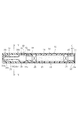
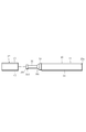
- the flavor suction pipe of one embodiment includes a tube-shaped pipe body 10, which is formed of a synthetic resin and has open ends.
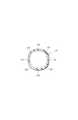
- the cross section of the pipe body 10 does not have a circular outline, but has a shape similar to a square.
- the cross-section ring is formed of four large circular arc surfaces 10a similar to a flat surface and four small circular arc surfaces 10b connecting these circular arc surfaces 10a. These circular arc surfaces 10b are as shown in FIG.
- the four stripes 11 are formed on the outer peripheral surface of the pipe body 10. These stripes 11 extend in the axial direction of the pipe body 10 and are arranged around the axis of the pipe body 10 with an interval of 90 °.
- a cylindrical tobacco cartridge 12 is concentrically accommodated as a flavor generating cartridge in the pipe body 10, and the tobacco cartridge 12 can move in the pipe body 10 in the axial direction and the circumferential direction. is there.
- the tobacco cartridge 12 includes a tube 14, and end pieces 16 and 18 are inserted into both ends of the tube 14, respectively.
- These end pieces 16 and 18 have a hollow sleeve shape and include projecting ends 16 a and 18 a projecting from the distal end and proximal end of the tube 14.
- These projecting ends 16a and 18a have a stepped shape, and have a flange-shaped large diameter portion in contact with an end surface on the corresponding side of the tube 14, and a small diameter portion extending from the large diameter portion.
- the outer diameter of the large diameter portion is substantially equal to the outer diameter of the tube 14, but the outer diameter of the small diameter portion is smaller than the outer diameter of the tube 14.
- annular protrusion 20 projects integrally from the inner peripheral surface of the tip of the pipe body 10, and this annular protrusion 20 provides an insertion hole 22 at the tip of the pipe body 10.
- the inner diameter of the insertion hole 22 is slightly larger than the outer diameter of the small diameter portion at the protruding end 16a. Therefore, the small diameter portion of the protruding end 16a is removably inserted into the insertion hole 22 as shown in FIG. Yes.
- a predetermined gap G is secured between the large diameter portion of the protruding end 16a and the annular protrusion 20.
- the tube 14 and the end pieces 16 and 18 mentioned above are formed from a synthetic resin, it is preferable that the tube 14 is transparent or translucent.
- cylindrical filters 24 and 26 are disposed in the tube 14 adjacent to the end pieces 16 and 18, respectively, and these filters 24 and 26 include a bundle of acetate fibers and a packaging material for wrapping the bundle. Including.
- a filling chamber is formed between the filters 24 and 26 in the tube 14, and the filling material is filled with the tobacco material T at a predetermined density.
- the tobacco material includes chopped tobacco and a perfume added to the chopped tobacco.
- a plurality of ribs 28 are integrally formed on the inner peripheral surface of the tube 14. These ribs 28 extend between the filters 24 and 26 in the axial direction of the tube 14 and are arranged at intervals in the circumferential direction of the tube 14 as is apparent from FIG. Such a rib 28 contributes to the thinning of the tube 14 while maintaining the strength of the tube 14, and also serves as a stopper for the filters 24 and 26.
- a predetermined distance is secured between the protruding end 18a of the end piece 18 and the base end of the pipe body 10, and a hollow mouthpiece 30 is detachably connected to a small diameter portion of the protruding end 18a.
- the hollow mouthpiece 30 is made of synthetic resin, and the cylindrical large diameter portion 30a, the tapered portion 30b, and the flat stem portion 30c are sequentially formed from the protruding end 18a side of the end piece 18.
- the stem portion 30c has a rectangular bulge portion 30d at its end, and the bulge portion 30d is larger than the stem portion 30c and has a pair of flat surfaces 30e parallel to each other.
- the large-diameter portion 30a of the mouthpiece 30 is removably inserted into the proximal end of the pipe body 10, while the small-diameter portion of the protruding end 18a is removably inserted into the large-diameter portion 30a of the mouthpiece 30. Yes.
- the flange of the end piece 18 is in a state of being sandwiched between the large diameter portion 30 a of the mouthpiece 30 and the tube 14. That is, the large-diameter portion 30a of the mouthpiece 30 has an outer diameter slightly smaller than the inner diameter of the pipe body 10, and has an inner diameter slightly larger than the outer diameter of the small-diameter portion of the protruding end 18a.
- the cap 32 has a hollow cylindrical shape and has an open end and a closed end.
- the open end of the cap 32 has an inner diameter slightly larger than the outer diameter of the large-diameter portion 30a of the mouthpiece 30. Therefore, the cap 32 receives the protruding part of the mouthpiece 30 from the opening end side in the inside thereof, and the opening end is fitted to the large diameter portion 30a from the outside, so that the cap 32 is detachably coupled to the mouthpiece 30.
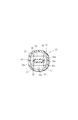
- the ring of the cross section of the cap 32 has the same size and shape as the ring of the cross section of the pipe body 10 described above. Therefore, as shown in FIG. There are four corresponding stripes 13.
- the open end of the cap 32 has a plurality of engagement recesses 34 on its inner surface, and these engagement recesses 34 are arranged at equal intervals in the circumferential direction of the cap 32.
- the large-diameter portion 30a of the mouthpiece 30 has engagement protrusions 36 for the respective engagement recesses 34 on the outer peripheral surface thereof, and these engagement protrusions 36 are also equally spaced in the circumferential direction of the mouthpiece 30.
- the cap 32 is put on the protruding portion of the mouthpiece 30 and the engaging projection 36 corresponding to the engaging recess 34 is fitted, the cap 32 is detachably coupled to the mouthpiece 30.
- Such engagement between the engagement recess 34 and the engagement protrusion 36 prevents the cap 32 from being undesirably detached from the mouthpiece 30, and the cap 32 is normally put on the mouthpiece 30. Let the user know that.
- ribs 38 are formed on the inner peripheral surface of the cap 32 on the closed end side of the cap 32. These ribs 38 extend in the axial direction of the cap 32 and are arranged at intervals in the circumferential direction of the cap 32.
- FIG. 5 shows that not only the four ribs 38 sandwich the bulging portion 30d in the first posture indicated by the solid line, but also the bulging portion 30d, that is, the mouthpiece 30 is relative to the first posture by 90 °. This also shows that the bulging portion 30d can be clamped even in the second posture indicated by the two-dot chain line that is rotated.
- the above-described sandwiching of the bulging portion 30d by the rib 38 couples the cap 32 and the mouthpiece 30 to each other in the circumferential direction regardless of the posture of the bulging portion 30d.
- the stripes 13 and the corresponding stripes 11 of the pipe body 10 are aligned with each other. That is, when the cap 32 is normally put on the mouthpiece 30, each stripe 13 of the cap 32 is positioned on the corresponding stripe 11 of the pipe body 10 in the circumferential direction of the pipe body 10 and the cap 32.
- the large-diameter portion 30a of the mouthpiece 30 is not only coupled to the end piece 18 of the tobacco cartridge 12 but also separably coupled to the proximal end of the pipe body 10 via the coupling device 40.
- the coupling device 40 is shown in detail in FIGS. 6 and 7, and the coupling device 40 will be described below.
- the proximal end of the pipe body 10 has a circumferential groove 42 on its inner peripheral surface.
- the circumferential groove 42 is opened at the base end surface of the pipe body 10, and an annular stopper surface 44 is provided on the inner peripheral surface of the pipe body 10.
- a flange 46 is integrally formed on the outer peripheral surface of the large-diameter portion 30 a of the mouthpiece 30, and the flange 46 is positioned on the proximal end side of the pipe body 10 with respect to the engagement protrusion 36 described above. .
- the aforementioned engagement protrusion 36 can be fitted into the engagement recess 34 in a state where the end surface of the cap 32 is in contact with the flange 46. That is, the flange 46 functions as a stopper for the cap 32 and determines the axial position of the cap 32 with respect to the mouthpiece 30. It should be noted that when the cap 32 is normally covered, a predetermined interval is secured between the inner surface of the closed end of the cap 32 and the end of the mouthpiece 30 as is apparent from FIG. It is.
- the flange 46 has an outer diameter that is slightly smaller than the inner diameter of the circumferential groove 42, and therefore, as is apparent from FIG. 6A, the flange 46 is partially in the circumferential groove 42. .
- an annular elastic member so-called O-ring 48
- O-ring 48 is attached to the outer peripheral surface of the large-diameter portion 30 a of the mouthpiece 30.
- the O-ring 48 is sandwiched between the end face of the flange 46 opposite to the engagement protrusion 36 and the stopper face 44 of the circumferential groove 42.
- O-ring 48 both have an outer diameter smaller than the inner diameter of the circumferential groove 42, the width D 0 when in the free state is the same as the width of, for example circumferential groove 42. Therefore, as described above, when the flange 46 partially enters the circumferential groove 42, the O-ring 48 is compressed between the flange 46 and the stopper surface 44 in the axial direction of the mouthpiece 30. , the width D 1 of the O-ring 48 at this time is smaller than the width D 0 as is apparent from FIG. 6 (B).
- the O-ring 48 urges the mouthpiece 30 in the direction in which the mouthpiece 30 is pulled out from the proximal end of the pipe body 10.
- the piece 30 is blocked by being locked to the pipe body 10.
- the large-diameter portion 30a of the mouthpiece 30 has at least one locking claw 50 on its outer peripheral surface, in the case of this embodiment.
- These locking claws 50 are spaced apart from each other in the diameter direction of the mouthpiece 30 and are positioned closer to the distal end side of the large-diameter portion 30 a than the O-ring 48.
- two guide grooves 52 are formed on the inner peripheral surface of the pipe body 10, and these guide grooves 52 are separated from each other in the diameter direction of the pipe body 10 and receive corresponding locking claws 50.
- Each guide groove 52 has a receiving seat facing the distal end side of the pipe body 10, and the locking claw 50 abuts against the receiving seat with a predetermined pressing force.
- the pressing force here is obtained by the aforementioned urging force of the mouthpiece 30, that is, the restoring force of the O-ring 48 resulting from the compression of the O-ring 48.
- the mouthpiece 30 is securely coupled to the proximal end of the pipe body 10, and the mouthpiece 30 is detached from the pipe body 10 together with the cap 32. None do.
- the guide groove 52 includes an axial portion 52a that extends in the axial direction of the pipe body 10 and opens at the stopper surface 44 of the circumferential groove 42 described above, and this axial portion.
- a circumferential portion 52b connected to the inner end of 52a. The circumferential portion 52b extends from the inner end of the axial portion 52a over a predetermined length in the circumferential direction of the pipe body 10.
- At least the groove wall facing the end surface of the circumferential portion 52b is not parallel to the axis of the pipe body 10 and is inclined in the extending direction of the circumferential portion 52b. It is preferable.
- the groove wall located on the stopper surface 44 side provides the aforementioned seat.
- a recess is formed in the groove wall, and the recess cooperates with the end surface of the circumferential portion 52b to form a concave claw rest 54 that allows the locking claw 50 to be fitted. Therefore, when the latching claw 50 is fitted in the claw rest 54 (the coupling position of the coupling device 40), the claw rest 54 restrains the latching claw 50 from three directions and engages in a direction in which the claw rest 54 comes out of the pipe body 10. The movement of the pawl 50 and the movement of the locking pawl 50 in the circumferential direction of the pipe body 10 are prevented. As a result, the mouthpiece 30 is prevented from shaking not only in the axial direction of the pipe body 10 but also in the circumferential direction thereof.
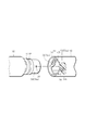
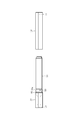
- the user uses the flavor suction pipe of the embodiment described above, first, the user pulls the cap 32 straight out of the mouthpiece 30 in the axial direction of the mouthpiece 30, and the engagement recess 34 of the cap 32 and the mouthpiece 30 are If the engagement with the engagement protrusion 36 is released and then the cap 32 is further pulled out, the cap 32 is removed from the mouthpiece 30 as shown in FIG. 8, and the mouthpiece 30 is exposed. .
- the user holds the bulging portion 30d of the mouthpiece 30 in a horizontal position and sucks it through the mouthpiece 30 to add the original flavor and taste of the tobacco in the tobacco cartridge 12 to the tobacco.
- the inside of the cigarette cartridge 12 is filled with a scent component volatilized from chopped cigarettes or fragrances
- the user's suction is the air from the tip of the pipe body 10 through the cigarette cartridge 12 and the mouthpiece 30 to the user's mouth Generate a flow of Therefore, the scent component is guided into the user's mouth along with the air flow, and as a result, the user can taste the scent component without igniting the cigarette.
- the pipe body 10 can be stably held.
- the user can remove the tobacco cartridge 12 together with the cap 32 and the mouthpiece 30 from the pipe body 10 as shown in FIG.
- the user pushes the cap 32 toward the direction of arrow F in FIG.
- the tip of the cap 32 is brought into contact with the flange 46 of the mouthpiece 30 and the tip of the mouthpiece 30 is in contact with the flange of the end piece 18 of the cigarette cartridge 12, so that the cap 32 is pushed in.
- the piece 30 and the tobacco cartridge 12 are moved in the axial direction toward the distal end side of the pipe body 10.
- the movement of the cigarette cartridge 12 here is because the gap G (see FIG. 2) is secured between the flange of the end piece 16 and the annular protrusion 20 of the pipe body 10 as described above. Permissible.
- the restoring force of the O-ring 48 in the compressed state pushes the mouthpiece 30 back in the direction of jumping out from the pipe body 10. Therefore, while the width of the O-ring 48 returns from D 2 to D 0 , the locking claw 50 moves along the axial portion 52 a of the guide groove 52 toward the opening end side of the guide groove 52.
- the cigarette cartridge 12 is separated from the mouthpiece 30, and the new cigarette cartridge 12 is coupled to the mouthpiece 30 by inserting the end piece 18 of the new cigarette cartridge 12 into the mouthpiece 30.
- the user inserts a new cigarette cartridge 12 into the pipe body 10 while holding the cap 32, and aligns the locking claw 50 of the mouthpiece 30 with the open end of the corresponding guide groove 52 of the pipe body 10. 7 (see FIG. 7), the large-diameter portion 30a of the mouthpiece 30 is pushed into the proximal end of the pipe body 10, and the locking claw 50 is advanced into the axial portion 52a of the guide groove 52. At this time, since the O-ring 48 of the mouthpiece 30 is sandwiched between the flange 46 of the mouthpiece 30 and the stopper surface 44 of the pipe body 10, the locking claw 50 has the guide groove 52 while the O-ring 48 is compressed. Is positioned in the circumferential portion 52b (see FIG. 10B).
- the cap 32 is integrally coupled to the mouthpiece 30 in the circumferential direction as described above.
- the mouthpiece 30 and the cigarette cartridge 12 also rotate clockwise. Therefore, the locking claw 50 abuts against the end surface of the circumferential portion 52b (see FIG. 10A), and when the user releases the pushing force of the cap 32 and the mouthpiece 30 in this state, FIG. As shown in FIG. 4, the latching claw 50 is reinserted into the claw rest 54 of the guide groove 52, and at this point, the replacement of the cigarette cartridge 12 is completed.
- the stripe 13 of the cap 32 is aligned with the corresponding stripe 11 of the pipe body 10.
- the tobacco cartridge 12 can be replaced by inserting a new tobacco cartridge 12 into the pipe body 10 and then pushing the mouthpiece 30 held by the cap 32 into the pipe body 10.
- the mouthpiece 30 is held via the cap 32, so that the user's finger does not touch the mouthpiece 30 directly. Therefore, the user can hygienically replace the cigarette cartridge 12.
- the cigarette cartridge 12 can be replaced without using the cap 32. That is, in this case, the user performs the above-described pushing and rotating operations of the mouthpiece 30 while directly holding the mouthpiece 30.
- the tobacco cartridge 12 to be replaced is pulled out from the pipe body 10 together with the mouthpiece 30, so that the tobacco cartridge 12 can be reliably and easily extracted from the pipe body 10.
- the tobacco cartridge 12 itself is not undesirably dropped from the pipe body 10.
- the present invention is not limited to the flavor suction pipe of the above-described embodiment, and various modifications are possible.
- a flavor generating cartridge containing various flavor generating materials can be used instead of the tobacco cartridge 12, and in this case, the user can taste the flavor components released from the flavor generating material. Can do.
- the pipe body 10 and the cap 32 can be divided and provided with a series of patterns on their outer peripheral surfaces instead of the stripes 11 and 13 described above.
- the pattern part of the pipe body 10 and the pattern part of the cap 32 are aligned with each other when the cap 32 is put on the mouthpiece 30 to form a continuous pattern.
- the coupling device 40 can use an elastic member such as a compression coil spring in place of the O-ring 48, and the specific structure of the cigarette cartridge, mouthpiece, cap and the like does not impair the function of the coupling device 40. As long as it can be changed arbitrarily.
- an elastic member such as a compression coil spring
- Pipe body 12 Tobacco cartridge 30 Mouthpiece 30a Large diameter part (tip part) 32 Cap 40 Coupling device 42 Circumferential groove 44 Stopper surface (step surface) 46 Flange 48 O-ring (elastic member) 50 Claw 52 Guide groove 52a Axial portion 52b Circumferential portion 54 Claw rest 56a, 56b Stripe (pattern)
Landscapes
- Health & Medical Sciences (AREA)
- Engineering & Computer Science (AREA)
- Life Sciences & Earth Sciences (AREA)
- Public Health (AREA)
- Anesthesiology (AREA)
- Biomedical Technology (AREA)
- Heart & Thoracic Surgery (AREA)
- Hematology (AREA)
- Bioinformatics & Cheminformatics (AREA)
- Animal Behavior & Ethology (AREA)
- General Health & Medical Sciences (AREA)
- Pulmonology (AREA)
- Veterinary Medicine (AREA)
- Quick-Acting Or Multi-Walled Pipe Joints (AREA)
- Medicinal Preparation (AREA)
- Packaging Of Annular Or Rod-Shaped Articles, Wearing Apparel, Cassettes, Or The Like (AREA)
- Disinfection, Sterilisation Or Deodorisation Of Air (AREA)
- Infusion, Injection, And Reservoir Apparatuses (AREA)
- Manufacture Of Tobacco Products (AREA)
Abstract
Priority Applications (11)
| Application Number | Priority Date | Filing Date | Title |
|---|---|---|---|
| HK13102958.1A HK1175420B (en) | 2010-02-24 | Flavor inhalation pipe | |
| ES10846495.9T ES2528950T3 (es) | 2010-02-24 | 2010-02-24 | Pipa de inhalación de aroma |
| CA2789362A CA2789362C (fr) | 2010-02-24 | 2010-02-24 | Tube d'inhalation d'arome |
| EP10846495.9A EP2540333B1 (fr) | 2010-02-24 | 2010-02-24 | Tube d'inhalation d'arôme |
| RU2012140439/12A RU2517122C2 (ru) | 2010-02-24 | 2010-02-24 | Трубка для вдыхания аромата |
| CN201080066410.6A CN102869403B (zh) | 2010-02-24 | 2010-02-24 | 香味吸入管 |
| PCT/JP2010/052835 WO2011104829A1 (fr) | 2010-02-24 | 2010-02-24 | Tube d'inhalation d'arôme |
| KR1020127021706A KR101424906B1 (ko) | 2010-02-24 | 2010-02-24 | 향미 흡인 파이프 |
| JP2012501568A JP5371134B2 (ja) | 2010-02-24 | 2010-02-24 | 香味吸引パイプ |
| UAA201211032A UA101940C2 (en) | 2010-02-24 | 2010-02-24 | Flavor inhalation pipe |
| US13/592,430 US9700691B2 (en) | 2010-02-24 | 2012-08-23 | Flavor inhalation pipe |
Applications Claiming Priority (1)
| Application Number | Priority Date | Filing Date | Title |
|---|---|---|---|
| PCT/JP2010/052835 WO2011104829A1 (fr) | 2010-02-24 | 2010-02-24 | Tube d'inhalation d'arôme |
Related Child Applications (1)
| Application Number | Title | Priority Date | Filing Date |
|---|---|---|---|
| US13/592,430 Continuation US9700691B2 (en) | 2010-02-24 | 2012-08-23 | Flavor inhalation pipe |
Publications (1)
| Publication Number | Publication Date |
|---|---|
| WO2011104829A1 true WO2011104829A1 (fr) | 2011-09-01 |
Family
ID=44506276
Family Applications (1)
| Application Number | Title | Priority Date | Filing Date |
|---|---|---|---|
| PCT/JP2010/052835 Ceased WO2011104829A1 (fr) | 2010-02-24 | 2010-02-24 | Tube d'inhalation d'arôme |
Country Status (10)
| Country | Link |
|---|---|
| US (1) | US9700691B2 (fr) |
| EP (1) | EP2540333B1 (fr) |
| JP (1) | JP5371134B2 (fr) |
| KR (1) | KR101424906B1 (fr) |
| CN (1) | CN102869403B (fr) |
| CA (1) | CA2789362C (fr) |
| ES (1) | ES2528950T3 (fr) |
| RU (1) | RU2517122C2 (fr) |
| UA (1) | UA101940C2 (fr) |
| WO (1) | WO2011104829A1 (fr) |
Cited By (10)
| Publication number | Priority date | Publication date | Assignee | Title |
|---|---|---|---|---|
| WO2013118299A1 (fr) * | 2012-02-10 | 2013-08-15 | 日本たばこ産業株式会社 | Inhalateur |
| GB2502052A (en) * | 2012-05-14 | 2013-11-20 | Nicoventures Holdings Ltd | Smokeless cigarette |
| JP2016535588A (ja) * | 2013-10-18 | 2016-11-17 | ニコベンチャーズ ホールディングス リミテッド | 電子式蒸気供給装置 |
| JP2018509897A (ja) * | 2015-02-27 | 2018-04-12 | ブリティッシュ アメリカン タバコ (インヴェストメンツ) リミテッドBritish American Tobacco (Investments) Limited | 喫煙物及び喫煙物用マウスピース |
| JP2018527901A (ja) * | 2015-07-17 | 2018-09-27 | アール・エイ・アイ・ストラテジック・ホールディングス・インコーポレイテッド | エアロゾル送達デバイスを補充するための液体収容システム |
| JP6593912B1 (ja) * | 2018-10-26 | 2019-10-23 | 日本たばこ産業株式会社 | エアロゾル生成装置の本体ユニット、エアロゾル生成装置及び非燃焼式吸引器 |
| US10667551B2 (en) | 2015-02-27 | 2020-06-02 | British American Tobacco (Investments) Limited | Smoking article and mouthpiece therefor |
| JP2021500885A (ja) * | 2017-10-24 | 2021-01-14 | ニコベンチャーズ トレーディング リミテッド | 電子エアロゾル供給デバイス |
| US11452826B2 (en) | 2016-03-24 | 2022-09-27 | Nicoventures Trading Limited | Mechanical connector for electronic vapor provision system |
| WO2023281682A1 (fr) * | 2021-07-08 | 2023-01-12 | 日本たばこ産業株式会社 | Unité corps principal de dispositif de génération d'aérosol, dispositif de génération d'aérosol, et appareil pour inhalation de type sans combustion |
Families Citing this family (68)
| Publication number | Priority date | Publication date | Assignee | Title |
|---|---|---|---|---|
| GB201118842D0 (en) * | 2011-11-01 | 2011-12-14 | Euro Celtique Sa | Dispenser cap arrangement |
| US9282772B2 (en) | 2012-01-31 | 2016-03-15 | Altria Client Services Llc | Electronic vaping device |
| USD695449S1 (en) | 2013-01-14 | 2013-12-10 | Altria Client Services Inc. | Electronic smoking article |
| USD841231S1 (en) | 2013-01-14 | 2019-02-19 | Altria Client Services, Llc | Electronic vaping device mouthpiece |
| USD691765S1 (en) | 2013-01-14 | 2013-10-15 | Altria Client Services Inc. | Electronic smoking article |
| USD849993S1 (en) | 2013-01-14 | 2019-05-28 | Altria Client Services | Electronic smoking article |
| USD691766S1 (en) | 2013-01-14 | 2013-10-15 | Altria Client Services Inc. | Mouthpiece of a smoking article |
| US9609893B2 (en) * | 2013-03-15 | 2017-04-04 | Rai Strategic Holdings, Inc. | Cartridge and control body of an aerosol delivery device including anti-rotation mechanism and related method |
| WO2015013329A1 (fr) * | 2013-07-25 | 2015-01-29 | Altria Client Services Inc. | Article à fumer électronique |
| CN203353691U (zh) * | 2013-07-26 | 2013-12-25 | 刘秋明 | 电子烟 |
| US20160198769A1 (en) * | 2013-08-23 | 2016-07-14 | Kimree Hi-Tech Inc. | Atomization assembly and electronic cigarette |
| BR302014001648S1 (pt) | 2013-10-14 | 2015-06-09 | Altria Client Services Inc | Configuração aplicada em artigo de fumo |
| CN104106843B (zh) * | 2014-06-03 | 2017-02-22 | 深圳麦克韦尔股份有限公司 | 电子烟烟嘴及电子烟 |
| USD755440S1 (en) * | 2014-06-26 | 2016-05-03 | Spark Ltd. | Pipe |
| US10624391B2 (en) * | 2014-09-26 | 2020-04-21 | Shenzhen Smoore Technology Limited | Inhaler, atomizing assembly and atomizing core |
| CN104544575B (zh) * | 2015-01-20 | 2021-01-29 | 卓尔悦欧洲控股有限公司 | 雾化器及其电子烟 |
| GB201501060D0 (en) | 2015-01-22 | 2015-03-11 | Nicoventures Holdings Ltd | Vapour provision system and cartridge therefor |
| WO2016119119A1 (fr) * | 2015-01-27 | 2016-08-04 | 惠州市吉瑞科技有限公司 | Atomiseur et cigarette électronique |
| CN104738817B (zh) * | 2015-02-12 | 2017-07-07 | 湖北中烟工业有限责任公司 | 无烟香烟 |
| US10226073B2 (en) | 2015-06-09 | 2019-03-12 | Rai Strategic Holdings, Inc. | Electronic smoking article including a heating apparatus implementing a solid aerosol generating source, and associated apparatus and method |
| CN110710717B (zh) * | 2015-07-14 | 2023-04-25 | 戴纳威普有限责任公司 | 放热汽化器 |
| US11092578B2 (en) | 2015-12-07 | 2021-08-17 | Shimadzu Corporation | Opening sealing structure, sample vaporization unit, and gas chromatograph |
| CN105725278B (zh) * | 2016-03-31 | 2019-05-28 | 卓尔悦欧洲控股有限公司 | 一种电子烟 |
| EP3406146B1 (fr) | 2016-01-18 | 2020-05-20 | Joyetech Europe Holding GmbH | Mécanisme de verrouillage élastique pour cigarette électronique, atomiseur et cigarette électronique |
| US20170208860A1 (en) * | 2016-01-22 | 2017-07-27 | Ii Daniel M. Evans | Smoking pipe assembly |
| JP1554858S (fr) * | 2016-01-25 | 2016-07-25 | ||
| KR102776989B1 (ko) * | 2016-01-25 | 2025-03-11 | 필립모리스 프로덕츠 에스.에이. | 나선형 작동을 갖는 카트리지 조립체 |
| US10883645B2 (en) | 2016-02-29 | 2021-01-05 | Shimadzu Corporation | Member linking mechanism and member linking method |
| KR102276436B1 (ko) | 2016-03-31 | 2021-07-12 | 조예테크 유럽 홀딩 게엠베하 | 배터리 장치 및 상기 배터리 장치를 갖춘 전자 담배 |
| US20170355495A1 (en) | 2016-06-08 | 2017-12-14 | N2 Packaging Systems, Llc | Child resistant and senior friendly can lid |
| WO2018000368A1 (fr) * | 2016-06-30 | 2018-01-04 | 惠州市吉瑞科技有限公司深圳分公司 | Cigarette électronique |
| USD861976S1 (en) | 2016-08-04 | 2019-10-01 | Nerudia Limited | Container for holding liquid for refilling an E-cigarette device |
| CN110191735A (zh) | 2016-12-12 | 2019-08-30 | Vmr产品有限责任公司 | 蒸发器 |
| UA127487C2 (uk) | 2016-12-16 | 2023-09-06 | Кт & Г Корпорейшон | Пристрій генерування аерозолю |
| USD898988S1 (en) * | 2017-03-27 | 2020-10-13 | Levinsonvapes, Incorporated | Atomizer cigar |
| RU2737855C1 (ru) | 2017-03-30 | 2020-12-03 | Кей Ти Энд Джи Корпорейшн | Устройство генерирования аэрозоля и держатель с возможностью размещения этого устройства |
| CN120642967A (zh) | 2017-04-11 | 2025-09-16 | 韩国烟草人参公社 | 卷烟 |
| US11771138B2 (en) | 2017-04-11 | 2023-10-03 | Kt&G Corporation | Aerosol generating device and method for providing smoking restriction function in aerosol generating device |
| US11432593B2 (en) | 2017-04-11 | 2022-09-06 | Kt&G Corporation | Device for cleaning smoking member, and smoking member system |
| US11622582B2 (en) | 2017-04-11 | 2023-04-11 | Kt&G Corporation | Aerosol generating device and method for providing adaptive feedback through puff recognition |
| JP6942814B2 (ja) | 2017-04-11 | 2021-09-29 | ケーティー・アンド・ジー・コーポレーション | ヒータを事前予熱するエアロゾル生成システム |
| US11197497B2 (en) | 2017-04-11 | 2021-12-14 | Kt&G Corporation | Aerosol generating device |
| CN110494051B (zh) | 2017-04-11 | 2022-09-23 | 韩国烟草人参公社 | 气溶胶生成装置 |
| KR102035313B1 (ko) | 2017-05-26 | 2019-10-22 | 주식회사 케이티앤지 | 히터 조립체 및 이를 구비한 에어로졸 생성 장치 |
| US11958666B2 (en) | 2017-06-07 | 2024-04-16 | N2 Packaging Systems, Llc | Child resistant double seam container lid |
| US11834237B2 (en) | 2017-06-07 | 2023-12-05 | N2 Packaging Systems, Llc | Child resistant double seam container lid adapter ring |
| CN116172276A (zh) | 2017-08-09 | 2023-05-30 | 韩国烟草人参公社 | 气溶胶生成装置及气溶胶生成装置控制方法 |
| US11849762B2 (en) | 2017-08-09 | 2023-12-26 | Kt&G Corporation | Electronic cigarette control method and device |
| JP6959429B2 (ja) | 2017-09-06 | 2021-11-02 | ケーティー・アンド・ジー・コーポレーション | エアロゾル生成装置 |
| USD861979S1 (en) * | 2017-10-10 | 2019-10-01 | N2 Packaging Systems, Llc | Snap-open preservation tube for tobacco and tobacco-like products |
| GB201717480D0 (en) | 2017-10-24 | 2017-12-06 | Nicoventures Holdings Ltd | Electronic aerosol provision device with seal |
| GB201717486D0 (en) | 2017-10-24 | 2017-12-06 | Nicoventures Holdings Ltd | Mechanism for hatch of electronic aerosol provision device |
| GB201717479D0 (en) | 2017-10-24 | 2017-12-06 | Nicoventures Holdings Ltd | Hatch section for an electronic aerosol provision device |
| GB201717484D0 (en) | 2017-10-24 | 2017-12-06 | Nicoventures Holdings Ltd | Electronic aerosol provision device |
| USD850712S1 (en) * | 2017-11-11 | 2019-06-04 | Avanzato Technology Corp. | Oval vaporizer assembly |
| USD860522S1 (en) * | 2018-01-10 | 2019-09-17 | Thomas Li | Pod adapter |
| USD874721S1 (en) * | 2018-01-18 | 2020-02-04 | Shenzhen Smoore Technology Limited | Electronic cigarette power supply device |
| CN109043640A (zh) * | 2018-09-27 | 2018-12-21 | 深圳市科伊斯科技有限公司 | 一种烟草烟弹及其香烟空气加热装置 |
| IT201800010935A1 (it) * | 2018-12-10 | 2020-06-10 | Patrizia Gioia | "dispositivo per la protezione igienica dei filtri delle sigarette" |
| USD862795S1 (en) | 2019-01-22 | 2019-10-08 | Lerman Container Corporation | Cartridge tube |
| WO2020154394A1 (fr) | 2019-01-22 | 2020-07-30 | Lerman Container Corporation | Tube de cartouche |
| US11344066B2 (en) | 2019-05-15 | 2022-05-31 | Vaporous Technologies, Inc. | Personal vaporizer and method for filling same |
| US11839238B2 (en) | 2019-05-15 | 2023-12-12 | Vaporous Technologies, Inc. | Personal vaporizer and method for filling same |
| US11330838B2 (en) * | 2019-07-19 | 2022-05-17 | R. J. Reynolds Tobacco Company | Holder for aerosol delivery device with detachable cartridge |
| KR102330807B1 (ko) * | 2019-07-29 | 2021-11-24 | 주식회사 케이티앤지 | 카트리지 및 이를 포함하는 에어로졸 발생 장치 |
| US12053030B2 (en) | 2022-09-18 | 2024-08-06 | Rdfn Fum Natural Products Ltd | Devices and systems for delivery of compounds and related methods |
| US12114693B2 (en) | 2022-09-18 | 2024-10-15 | RDFN FUM Natural Products Ltd. | Non-electric, non-heated devices for oral delivery of compounds and related systems and methods |
| US11937633B1 (en) | 2023-05-25 | 2024-03-26 | Next Level Ventures LLC | Vaping mouthpiece locking structure |
Citations (7)
| Publication number | Priority date | Publication date | Assignee | Title |
|---|---|---|---|---|
| JPS539509A (en) | 1976-07-14 | 1978-01-28 | Hitachi Ltd | Production of magnetic head |
| JPS539509Y2 (fr) * | 1973-06-06 | 1978-03-13 | ||
| JPS63188039U (fr) | 1987-05-26 | 1988-12-01 | ||
| JPH022331A (ja) | 1988-03-30 | 1990-01-08 | Kowa Display:Kk | 無煙煙草 |
| JPH039678Y2 (fr) * | 1987-10-21 | 1991-03-11 | ||
| US5535735A (en) * | 1995-03-22 | 1996-07-16 | Mcpherson; Andrew | Simulated cigarette inhaler |
| JP2002000331A (ja) * | 2000-06-22 | 2002-01-08 | Kaburagi Kikaku:Kk | 携帯品用支持具 |
Family Cites Families (15)
| Publication number | Priority date | Publication date | Assignee | Title |
|---|---|---|---|---|
| GB191218322A (en) * | 1912-08-09 | 1913-01-09 | Walter Harrop | A New or Improved Cap for Tobacco Pipe Mouthpieces. |
| US2124221A (en) * | 1935-10-30 | 1938-07-19 | Jacobs Samuel M Jackson | Tobacco pipe |
| US2119198A (en) * | 1937-05-21 | 1938-05-31 | Bruder Edmund | Smoking tube |
| US3200819A (en) * | 1963-04-17 | 1965-08-17 | Herbert A Gilbert | Smokeless non-tobacco cigarette |
| JPS539509B1 (fr) | 1971-07-21 | 1978-04-06 | ||
| US5167242A (en) * | 1990-06-08 | 1992-12-01 | Kabi Pharmacia Aktiebolaq | Nicotine-impermeable container and method of fabricating the same |
| US5273649A (en) * | 1991-10-07 | 1993-12-28 | Magnusson Jan H | Personal water purification systems |
| US6196218B1 (en) * | 1999-02-24 | 2001-03-06 | Ponwell Enterprises Ltd | Piezo inhaler |
| JP2002119271A (ja) * | 2000-10-10 | 2002-04-23 | ▲せつ▼清芳 | たばこフィルタの緊密圧縮器具 |
| CH698603B1 (de) * | 2005-04-29 | 2009-09-15 | Burger Soehne Man Ag | Inhalator. |
| FR2895644B1 (fr) * | 2006-01-03 | 2008-05-16 | Didier Gerard Martzel | Substitut de cigarette |
| US7726320B2 (en) * | 2006-10-18 | 2010-06-01 | R. J. Reynolds Tobacco Company | Tobacco-containing smoking article |
| CA2682432C (fr) * | 2007-03-30 | 2017-06-06 | Duke University | Dispositif et procede pour administrer un medicament |
| RU72821U1 (ru) * | 2007-06-15 | 2008-05-10 | Александр Васильевич Когут | Бездымное курительное изделие (варианты) |
| RU89927U1 (ru) * | 2009-07-22 | 2009-12-27 | Владимир Николаевич Урцев | Трубка для бездымного курения |
-
2010
- 2010-02-24 RU RU2012140439/12A patent/RU2517122C2/ru active
- 2010-02-24 CN CN201080066410.6A patent/CN102869403B/zh not_active Expired - Fee Related
- 2010-02-24 ES ES10846495.9T patent/ES2528950T3/es active Active
- 2010-02-24 EP EP10846495.9A patent/EP2540333B1/fr not_active Not-in-force
- 2010-02-24 JP JP2012501568A patent/JP5371134B2/ja not_active Expired - Fee Related
- 2010-02-24 KR KR1020127021706A patent/KR101424906B1/ko not_active Expired - Fee Related
- 2010-02-24 WO PCT/JP2010/052835 patent/WO2011104829A1/fr not_active Ceased
- 2010-02-24 UA UAA201211032A patent/UA101940C2/ru unknown
- 2010-02-24 CA CA2789362A patent/CA2789362C/fr active Active
-
2012
- 2012-08-23 US US13/592,430 patent/US9700691B2/en not_active Expired - Fee Related
Patent Citations (7)
| Publication number | Priority date | Publication date | Assignee | Title |
|---|---|---|---|---|
| JPS539509Y2 (fr) * | 1973-06-06 | 1978-03-13 | ||
| JPS539509A (en) | 1976-07-14 | 1978-01-28 | Hitachi Ltd | Production of magnetic head |
| JPS63188039U (fr) | 1987-05-26 | 1988-12-01 | ||
| JPH039678Y2 (fr) * | 1987-10-21 | 1991-03-11 | ||
| JPH022331A (ja) | 1988-03-30 | 1990-01-08 | Kowa Display:Kk | 無煙煙草 |
| US5535735A (en) * | 1995-03-22 | 1996-07-16 | Mcpherson; Andrew | Simulated cigarette inhaler |
| JP2002000331A (ja) * | 2000-06-22 | 2002-01-08 | Kaburagi Kikaku:Kk | 携帯品用支持具 |
Non-Patent Citations (1)
| Title |
|---|
| See also references of EP2540333A4 |
Cited By (21)
| Publication number | Priority date | Publication date | Assignee | Title |
|---|---|---|---|---|
| WO2013118299A1 (fr) * | 2012-02-10 | 2013-08-15 | 日本たばこ産業株式会社 | Inhalateur |
| GB2502052A (en) * | 2012-05-14 | 2013-11-20 | Nicoventures Holdings Ltd | Smokeless cigarette |
| WO2013171206A1 (fr) * | 2012-05-14 | 2013-11-21 | British American Tobacco (Nc) Limited | Dispositif de fourniture de vapeur électronique |
| JP2016535588A (ja) * | 2013-10-18 | 2016-11-17 | ニコベンチャーズ ホールディングス リミテッド | 電子式蒸気供給装置 |
| US10667551B2 (en) | 2015-02-27 | 2020-06-02 | British American Tobacco (Investments) Limited | Smoking article and mouthpiece therefor |
| JP2020099338A (ja) * | 2015-02-27 | 2020-07-02 | ブリティッシュ アメリカン タバコ (インヴェストメンツ) リミテッドBritish American Tobacco (Investments) Limited | 喫煙物及び喫煙物用マウスピース |
| JP2018509897A (ja) * | 2015-02-27 | 2018-04-12 | ブリティッシュ アメリカン タバコ (インヴェストメンツ) リミテッドBritish American Tobacco (Investments) Limited | 喫煙物及び喫煙物用マウスピース |
| US11406127B2 (en) | 2015-02-27 | 2022-08-09 | Nicoventures Trading Limited | Smoking article and mouthpiece therefor |
| US11425928B2 (en) | 2015-02-27 | 2022-08-30 | British American Tobacco (Investments) Limited | Smoking article and mouthpiece therefor |
| JP2018527901A (ja) * | 2015-07-17 | 2018-09-27 | アール・エイ・アイ・ストラテジック・ホールディングス・インコーポレイテッド | エアロゾル送達デバイスを補充するための液体収容システム |
| US12434023B2 (en) | 2015-07-17 | 2025-10-07 | Rai Strategic Holdings, Inc. | Contained liquid system for refilling aerosol delivery devices |
| US11998686B2 (en) | 2015-07-17 | 2024-06-04 | Rai Strategic Holdings, Inc. | Contained liquid system for refilling aerosol delivery devices |
| JP2021100415A (ja) * | 2015-07-17 | 2021-07-08 | アール・エイ・アイ・ストラテジック・ホールディングス・インコーポレイテッド | エアロゾル送達デバイスを補充するための液体収容システム |
| JP7104471B2 (ja) | 2015-07-17 | 2022-07-21 | アール・エイ・アイ・ストラテジック・ホールディングス・インコーポレイテッド | エアロゾル送達デバイスを補充するための液体収容システム |
| US11504489B2 (en) | 2015-07-17 | 2022-11-22 | Rai Strategic Holdings, Inc. | Contained liquid system for refilling aerosol delivery devices |
| US11452826B2 (en) | 2016-03-24 | 2022-09-27 | Nicoventures Trading Limited | Mechanical connector for electronic vapor provision system |
| JP2021500885A (ja) * | 2017-10-24 | 2021-01-14 | ニコベンチャーズ トレーディング リミテッド | 電子エアロゾル供給デバイス |
| JP7131610B2 (ja) | 2017-10-24 | 2022-09-06 | ニコベンチャーズ トレーディング リミテッド | 電子エアロゾル供給デバイス |
| WO2020084795A1 (fr) * | 2018-10-26 | 2020-04-30 | 日本たばこ産業株式会社 | Unité de corps destinée à un dispositif de génération d'aérosol, dispositif de génération d'aérosol et inhalateur de type sans combustion |
| JP6593912B1 (ja) * | 2018-10-26 | 2019-10-23 | 日本たばこ産業株式会社 | エアロゾル生成装置の本体ユニット、エアロゾル生成装置及び非燃焼式吸引器 |
| WO2023281682A1 (fr) * | 2021-07-08 | 2023-01-12 | 日本たばこ産業株式会社 | Unité corps principal de dispositif de génération d'aérosol, dispositif de génération d'aérosol, et appareil pour inhalation de type sans combustion |
Also Published As
| Publication number | Publication date |
|---|---|
| CN102869403B (zh) | 2015-01-28 |
| JPWO2011104829A1 (ja) | 2013-06-17 |
| KR20120109634A (ko) | 2012-10-08 |
| ES2528950T3 (es) | 2015-02-13 |
| EP2540333A1 (fr) | 2013-01-02 |
| US9700691B2 (en) | 2017-07-11 |
| UA101940C2 (en) | 2013-05-13 |
| CN102869403A (zh) | 2013-01-09 |
| RU2517122C2 (ru) | 2014-05-27 |
| EP2540333A4 (fr) | 2013-11-06 |
| EP2540333B1 (fr) | 2014-11-19 |
| JP5371134B2 (ja) | 2013-12-18 |
| CA2789362C (fr) | 2014-05-27 |
| KR101424906B1 (ko) | 2014-08-13 |
| HK1175420A1 (en) | 2013-07-05 |
| RU2012140439A (ru) | 2014-03-27 |
| CA2789362A1 (fr) | 2011-09-01 |
| US20120318283A1 (en) | 2012-12-20 |
Similar Documents
| Publication | Publication Date | Title |
|---|---|---|
| JP5371134B2 (ja) | 香味吸引パイプ | |
| CN105142433B (zh) | 吸气装置和吸入剂设备 | |
| WO2013118299A1 (fr) | Inhalateur | |
| JP5798185B2 (ja) | エアロゾル発生装置 | |
| CN105120694B (zh) | 吸入装置和用于吸入装置的部件 | |
| KR102765603B1 (ko) | 소모품 보유 메커니즘 | |
| US20190150513A1 (en) | Electronic cigarette and electronic cigarette cartridge | |
| EP3146856A1 (fr) | Seringue de remplissage pour un dispositif de cigarette électronique | |
| US20140034070A1 (en) | Aerosol Generator | |
| WO2004089126A1 (fr) | Tuyau d'aspiration de nicotine et support de nicotine | |
| US20200170295A1 (en) | Accessory E-Cigarette And Filter Sleeve Assembly | |
| US9538786B2 (en) | Inhalation device | |
| CN110214974B (zh) | 烟嘴香珠添加器 | |
| US6745777B2 (en) | Tobacco filter means superimposedly rechargeably filled with disposable filter units | |
| US20210161205A1 (en) | Accessory E-Cigarette And Filter Assembly | |
| JP2018507687A (ja) | 喫煙物品のための管 | |
| TWI412331B (zh) | 香氣吸入管 | |
| CN215013570U (zh) | 电子烟包装盒及电子烟套件 | |
| HK1175420B (en) | Flavor inhalation pipe | |
| AU2007100916A4 (en) | Safety Syring Device | |
| JP3232229U (ja) | タバコホルダー並びにこのタバコホルダーの販売セット | |
| WO2019038838A1 (fr) | Aspirateur d'arôme, boîtier de stockage pour unité source d'arôme et cendrier pourvu d'une partie de stockage d'unité source d'arôme | |
| TW201332461A (zh) | 抽吸器 | |
| US20080035163A1 (en) | Magnetic Advanced Cigarette Filtration System | |
| CN114515019B (zh) | 一种电子烟兼容件和兼容式烟弹以及电子烟 |
Legal Events
| Date | Code | Title | Description |
|---|---|---|---|
| WWE | Wipo information: entry into national phase |
Ref document number: 201080066410.6 Country of ref document: CN |
|
| 121 | Ep: the epo has been informed by wipo that ep was designated in this application |
Ref document number: 10846495 Country of ref document: EP Kind code of ref document: A1 |
|
| WWE | Wipo information: entry into national phase |
Ref document number: 2012501568 Country of ref document: JP |
|
| ENP | Entry into the national phase |
Ref document number: 2789362 Country of ref document: CA |
|
| ENP | Entry into the national phase |
Ref document number: 20127021706 Country of ref document: KR Kind code of ref document: A |
|
| WWE | Wipo information: entry into national phase |
Ref document number: 2010846495 Country of ref document: EP |
|
| NENP | Non-entry into the national phase |
Ref country code: DE |
|
| WWE | Wipo information: entry into national phase |
Ref document number: A201211032 Country of ref document: UA |
|
| WWE | Wipo information: entry into national phase |
Ref document number: 2012140439 Country of ref document: RU |