WO2011105144A1 - Dispositif et méthode de traitement d'objet en forme de bande - Google Patents
Dispositif et méthode de traitement d'objet en forme de bande Download PDFInfo
- Publication number
- WO2011105144A1 WO2011105144A1 PCT/JP2011/051149 JP2011051149W WO2011105144A1 WO 2011105144 A1 WO2011105144 A1 WO 2011105144A1 JP 2011051149 W JP2011051149 W JP 2011051149W WO 2011105144 A1 WO2011105144 A1 WO 2011105144A1
- Authority
- WO
- WIPO (PCT)
- Prior art keywords
- roll
- strip
- slit
- transfer
- sheet
- Prior art date
- Legal status (The legal status is an assumption and is not a legal conclusion. Google has not performed a legal analysis and makes no representation as to the accuracy of the status listed.)
- Ceased
Links
Images



Classifications
-
- A—HUMAN NECESSITIES
- A61—MEDICAL OR VETERINARY SCIENCE; HYGIENE
- A61F—FILTERS IMPLANTABLE INTO BLOOD VESSELS; PROSTHESES; DEVICES PROVIDING PATENCY TO, OR PREVENTING COLLAPSING OF, TUBULAR STRUCTURES OF THE BODY, e.g. STENTS; ORTHOPAEDIC, NURSING OR CONTRACEPTIVE DEVICES; FOMENTATION; TREATMENT OR PROTECTION OF EYES OR EARS; BANDAGES, DRESSINGS OR ABSORBENT PADS; FIRST-AID KITS
- A61F13/00—Bandages or dressings; Absorbent pads
- A61F13/15—Absorbent pads, e.g. sanitary towels, swabs or tampons for external or internal application to the body; Supporting or fastening means therefor; Tampon applicators
- A61F13/56—Supporting or fastening means
- A61F13/5605—Supporting or fastening means specially adapted for sanitary napkins or the like
- A61F13/5616—Supporting or fastening means specially adapted for sanitary napkins or the like using flaps, e.g. adhesive, for attachment to the undergarment
-
- A—HUMAN NECESSITIES
- A61—MEDICAL OR VETERINARY SCIENCE; HYGIENE
- A61F—FILTERS IMPLANTABLE INTO BLOOD VESSELS; PROSTHESES; DEVICES PROVIDING PATENCY TO, OR PREVENTING COLLAPSING OF, TUBULAR STRUCTURES OF THE BODY, e.g. STENTS; ORTHOPAEDIC, NURSING OR CONTRACEPTIVE DEVICES; FOMENTATION; TREATMENT OR PROTECTION OF EYES OR EARS; BANDAGES, DRESSINGS OR ABSORBENT PADS; FIRST-AID KITS
- A61F13/00—Bandages or dressings; Absorbent pads
- A61F13/15—Absorbent pads, e.g. sanitary towels, swabs or tampons for external or internal application to the body; Supporting or fastening means therefor; Tampon applicators
- A61F13/15577—Apparatus or processes for manufacturing
- A61F13/15707—Mechanical treatment, e.g. notching, twisting, compressing, shaping
- A61F13/15723—Partitioning batts; Cutting
-
- A—HUMAN NECESSITIES
- A61—MEDICAL OR VETERINARY SCIENCE; HYGIENE
- A61F—FILTERS IMPLANTABLE INTO BLOOD VESSELS; PROSTHESES; DEVICES PROVIDING PATENCY TO, OR PREVENTING COLLAPSING OF, TUBULAR STRUCTURES OF THE BODY, e.g. STENTS; ORTHOPAEDIC, NURSING OR CONTRACEPTIVE DEVICES; FOMENTATION; TREATMENT OR PROTECTION OF EYES OR EARS; BANDAGES, DRESSINGS OR ABSORBENT PADS; FIRST-AID KITS
- A61F13/00—Bandages or dressings; Absorbent pads
- A61F13/15—Absorbent pads, e.g. sanitary towels, swabs or tampons for external or internal application to the body; Supporting or fastening means therefor; Tampon applicators
- A61F13/15577—Apparatus or processes for manufacturing
- A61F13/15804—Plant, e.g. involving several steps
-
- B—PERFORMING OPERATIONS; TRANSPORTING
- B65—CONVEYING; PACKING; STORING; HANDLING THIN OR FILAMENTARY MATERIAL
- B65H—HANDLING THIN OR FILAMENTARY MATERIAL, e.g. SHEETS, WEBS, CABLES
- B65H37/00—Article or web delivery apparatus incorporating devices for performing specified auxiliary operations
- B65H37/04—Article or web delivery apparatus incorporating devices for performing specified auxiliary operations for securing together articles or webs, e.g. by adhesive, stitching or stapling
-
- B—PERFORMING OPERATIONS; TRANSPORTING
- B65—CONVEYING; PACKING; STORING; HANDLING THIN OR FILAMENTARY MATERIAL
- B65H—HANDLING THIN OR FILAMENTARY MATERIAL, e.g. SHEETS, WEBS, CABLES
- B65H39/00—Associating, collating, or gathering articles or webs
- B65H39/14—Associating sheets with webs
-
- B—PERFORMING OPERATIONS; TRANSPORTING
- B65—CONVEYING; PACKING; STORING; HANDLING THIN OR FILAMENTARY MATERIAL
- B65H—HANDLING THIN OR FILAMENTARY MATERIAL, e.g. SHEETS, WEBS, CABLES
- B65H2801/00—Application field
- B65H2801/57—Diaper manufacture
Definitions
- the present invention relates to a strip processing apparatus and method.
- a cutter roll, an anvil roll arranged to face the cutter roll, and a nip roll arranged to face the anvil roll are provided, and a continuous sheet is supplied between the cutter roll and the anvil roll, and the cutter roll intermittently interrupts the continuous sheet. Is cut to form a release sheet piece, and the strip is conveyed so as to pass through the transfer position between the anvil roll and the nip roll, and the anvil roll transports the release sheet piece to the transfer position and then intermittently to the strip.
- an intermittent cutting transfer device for transferring to a sheet see Patent Document 1.
- the liquid-permeable top sheet, the liquid-impermeable back sheet, and the absorbent main body including the absorbent body arranged between the top sheet and the back sheet, and attached to the absorbent main body so as to cover the top sheet
- an absorbent article including a release sheet piece that covers the pressure-sensitive adhesive is also known (see Patent Document 2).
- a strip processing apparatus that intermittently forms a slit in a strip and transfers a sheet piece to the strip intermittently, comprising a slit forming roll, a transfer roll, An anvil roll disposed facing each of the slit forming roll and the transfer roll, and the strip passes through the slit forming position between the slit forming roll and the anvil roll and then between the transfer roll and the anvil roll.
- the slit forming roll is conveyed so as to pass through the transfer position, and at the slit forming position, a plurality of slits are intermittently formed in the belt-like body in the transport direction, and the transfer roll is a sheet that straddles the slits at the transfer position.
- a strip processing apparatus for intermittently transferring a piece to a strip is provided.
- a strip processing method for intermittently forming slits in a strip and intermittently transferring sheet pieces to the strip including a slit forming roll and a transfer roll And anvil rolls arranged to face the slit forming roll and the transfer roll, respectively, and the strips pass through the slit forming positions between the slit forming roll and the anvil roll arranged to face each other, and then to each other.
- a strip processing method in which a sheet piece is intermittently transferred to a strip at a transfer position by a transfer roll so as to straddle the slits. It is provided.
- ⁇ Sheet piece can be transferred while suppressing the formation of wrinkles or wrinkles on the band-like object having slits.
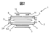
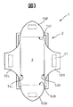
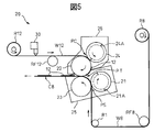
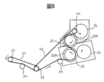
- FIG. 2 is a schematic cross-sectional view of the absorbent article taken along line II-II in FIG. 1. It is a front view of an absorptive article which developed a flap. It is the schematic which shows the manufacturing process of an absorbent article. It is the schematic of the manufacturing apparatus of a cover sheet complex. It is the schematic explaining the drive system of a manufacturing apparatus. It is a schematic diagram of the surrounding surface of an anvil roll. It is a figure which shows typically the manufacturing process of the cover sheet composite body C8 in a manufacturing apparatus.
- the absorbent main body 2 includes a liquid-permeable top sheet 3, a liquid-impermeable back sheet 4, and a liquid-retaining absorbent 5 disposed between the top sheet 3 and the back sheet 4.
- the top sheet 3 and the back sheet 4 have substantially the same size, and are joined and sealed to each other at the peripheral portion 2P by heat sealing, hot melt adhesive, or the like.
- an adhesive 6 for fixing the absorbent main body 2 to the underwear is applied to the outer surface of the back sheet 4 that is directed to clothing such as underwear during use, and this adhesive 6 is covered with a release sheet piece 7. ing.
- 1, 2F, 2B, 2L, and 2R indicate the front edge, the rear edge, the left edge, and the right edge of the napkin 1 or the absorbent main body 2, respectively.
- the front, rear, left and right in this case correspond to the front, back, left and right of the wearer's body.
- 5 ⁇ / b> A indicates a tissue disposed between the absorbent body 5 and the back sheet 3.
- the surface of the top sheet 3 that contacts the wearer during use is covered with a liquid-impermeable cover sheet 8.
- the cover sheet 8 is approximately the same size as the absorbent main body 2, and thus covers almost the entire surface of the top sheet 3.
- the cover sheet 8 is joined to the top sheet 3 or the absorbent main body 2 by heat sealing, hot melt adhesive, or the like in the annular peripheral region 8P.
- the central region 8C which is a region other than the peripheral region 8P, is not joined to the top sheet 3.
- a slit 9 is formed in the central region 8C of the cover sheet 8 in advance, and a plurality of flaps for fixing the absorbent main body 2 to the underwear are defined or formed in the central region 8C by the slit 9.
- the slit 9 is formed from a cutting line that completely cuts the cover sheet 8.
- the slit 9 can also be formed from a weak line such as a perforation. In the example shown in FIG.
- the slit 9 includes a U-shaped curved portion 9 ⁇ / b> F that expands toward the front edge 2 ⁇ / b> F, a U-shaped curved portion 9 ⁇ / b> B that expands toward the rear edge 2 ⁇ / b> B, and substantially the cover sheet 8. It is composed of a straight line portion 9S that connects the vertices of these curved portions 9F and 9B at the center.
- four flaps that is, a semi-oval front flap 10F and a rear flap 10B, and a trapezoidal left flap 10L and a right flap 10R are defined in the central region 8C.
- the front and rear flaps 10F and 10B are positioned symmetrically with each other, and the left and right flaps 10L and 10R are also positioned symmetrically with each other.
- the slit 9 branches into three at the connection point between the curved portions 9F and 9B and the straight portion 9S. That is, the slit 9 includes a branch portion 9D.
- Adhesives 11 for fixing the corresponding flaps 10F, 10B, 10L, and 10R to the underwear are applied to the outer surfaces of the flaps 10F, 10B, 10L, and 10R, respectively. These adhesives 11 are covered with a common release sheet piece 12.
- the release sheet piece 12 is provided so as to straddle the slit 9, and particularly provided so as to cover the branch portion 9D. If it does in this way, it can suppress reliably that a bullet etc. arise in flap 10F, 10B, 10L, 10R. Next, the material of each element will be described.
- the top sheet 3 is composed of, for example, a perforated or non-porous nonwoven fabric or a porous plastic sheet.
- the back sheet 4 is composed of, for example, a hydrophobic nonwoven fabric, a water-impermeable plastic film, a laminate sheet of a nonwoven fabric and a water-impermeable plastic film, a highly water-resistant melt-blown nonwoven fabric, and an SMS nonwoven fabric sandwiched between strong spunbond nonwoven fabrics.
- the absorbent body 5 is composed of, for example, fluffy pulp or air laid nonwoven fabric and a highly absorbent polymer.
- the fluffy pulp is composed of, for example, artificial cellulose fibers such as chemical pulp, cellulose fiber, rayon, and acetate
- the airlaid nonwoven fabric is composed of, for example, a nonwoven fabric obtained by thermally fusing pulp and synthetic fibers or fixing them with a binder.
- the superabsorbent polymer is composed of, for example, a starch-based, acrylic acid-based, or amino acid-based particulate or fibrous polymer.
- Adhesives 6 and 11 are hot melts such as styrene-isoprene-styrene block copolymer (SIS), styrene-butadiene-styrene block copolymer (SBS), styrene-ethylene-butylene-ethylene copolymer (SEBS), etc. Consists of an adhesive.
- the cover sheet 8 is composed of, for example, a hydrophobic nonwoven fabric, a water-impermeable plastic film, a laminate sheet of a nonwoven fabric and a water-impermeable plastic film, a highly water-resistant meltblown nonwoven fabric, or an SMS nonwoven fabric sandwiched between strong spunbond nonwoven fabrics. Preferably, it is composed of a hydrophobic nonwoven fabric.
- the basis weight of the cover sheet 8 is preferably 15 g / m 2 to 60 g / m 2 .
- the draping property of the plastic film is preferably 20 mm to 100 mm, more preferably 30 mm to 70 mm by the cantilever method.
- the above-mentioned cantilever method is performed as follows according to JIS-L1018. That is, a measurement sample is obtained by stacking five measurement objects having a length of 150 mm and a width of 25 mm.
- the measurement sample is sandwiched under the holding plate of the cantilever and slid in the slope direction to automatically measure the moving distance at a speed of 5 mm / sec. Measurement is performed both when the surface of the measurement sample is down and when the back surface of the measurement sample is down, and the average of these is taken as the measurement result.
- the absorbent article 1 is fixed to the underwear as follows. That is, first, the release sheet piece 7 on the back sheet 4 side is removed, and the absorbent article 1 or the absorbent main body 2 is fixed to the underwear via the adhesive 6. At this time, since the top sheet 3 is covered with the cover sheet 8, the top sheet 3 is prevented from being contaminated.
- these flaps 10F, 10B, 10L, and 10R are expanded. That is, the front flap 10F is folded in the folding region 14F along the front edge 2F and expanded in the forward direction, and the rear flap 10B is folded in the folding region 14B along the rear edge 2B and expanded in the rear direction. Further, the left flap 10L is folded in the folding region 14L along the left edge 2L and expanded leftward, and the right flap 10R is folded in the folding region 14R along the right edge 2R and expanded rightward. As a result, the top sheet 3 is exposed. Next, the flaps 10F, 10B, 10L, and 10R are fixed to the underwear via the respective adhesives 11.
- FIG. 4 schematically shows a manufacturing process of the absorbent article 1.
- a tissue web W5A which is a continuous body of tissue 5A, is conveyed in the conveyance direction MD, and the absorbent body 5 is intermittently arranged on the tissue web W5A, that is, spaced in the conveyance direction MD.
- An adhesive such as a hot melt adhesive is applied in advance to the upper surface of the tissue web W5A (S1A), and the absorbent body 5 is fixed to the tissue web W5A by this adhesive.
- a top sheet web W3, which is a continuous body of the top sheet 3, is superimposed on the absorbent body 5 (S2).
- the cover sheet composite C8 is overlaid on the outer surface of the top sheet web W3 (S3).
- the cover sheet composite C8 is obtained by intermittently providing an adhesive 11 and a release sheet piece 12 on a cover sheet web W8 that is a continuous body of the cover sheet 8.
- the back sheet composite C4 is overlaid on the lower surface of the tissue web W5A (S4).
- the backsheet composite C4 is obtained by intermittently providing the adhesive 6 and the release sheet pieces 7 on the backsheet web that is a continuous body of the backsheet 4.
- FIG. 5 shows a manufacturing apparatus 20 for the cover sheet composite C8.
- slits 9 are formed in a belt-like object, for example, a cover sheet web W 8 at intervals in the conveying direction MD, and the release sheet piece 12 is transferred to the cover sheet web W 8 so as to straddle the slit 9, thereby covering A sheet composite C8 is formed.
- the continuous sheet W12 that is a continuous body of the release sheet pieces 12 is intermittently cut, thereby forming the release sheet pieces 12, and then intermittently transferred to the cover sheet web W8.
- the adhesive 11 is applied in advance to the continuous sheet W12, and therefore the release sheet piece 12 is transferred to the cover sheet web W8 together with the adhesive 11.
- the manufacturing apparatus 20 is disposed to face the slit forming roll 21, the transfer roll 22, the anvil roll 23 arranged to face the slit forming roll 21 and the transfer roll 22, and the transfer roll 22. And a cutter roll 24.
- the rotation axes of these rolls 21, 22, 23, and 24 are parallel to each other.
- the slit forming roll 21 and the anvil roll 23 are rotatably supported by the frame 25, and the transfer roll 22 and the cutter roll 24 are rotatably supported by the frame 26.
- the slit forming roll 21, the transfer roll 22, the anvil roll 23, and the cutter roll 24 are rotationally driven by the same driving machine. That is, as shown in FIG.
- the driving force of the driving device 27 such as a servo motor is transmitted to the infinite belt V ⁇ b> 2 via the infinite belt V ⁇ b> 1 and the common pulley 28.
- the infinite belt V2 is hung around the pulley 23P of the anvil roll 23 and around the pulley 22P of the transfer roll 22, so that the anvil roll 23 and the transfer roll 22 are rotationally driven by the infinite belt V2.
- the slit forming roll 21 and the anvil roll 23 are connected to each other by a gear (not shown), and the transfer roll 22 and the cutter roll 24 are also connected to each other by a gear (not shown). Therefore, the four rolls 21, 22, 23, and 24 are rotationally driven by the same driving machine 27.
- PI indicates an idler pulley.
- the cover sheet web W8 rewound from the roll-shaped cover sheet web source R8 is formed with a slit between the slit forming roll 21 and the anvil roll 23 by the transport roll RF8 and the idle roll RI. It is conveyed to position PS.
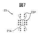
- a negative pressure is applied to the peripheral surface of the anvil roll 23 through a pressure port 23P as shown in FIG.
- the cover sheet web W8 is held on the peripheral surface of the anvil roll 23. Is done.
- the slit 9 is intermittently formed in the cover sheet web W8 by the blade 21A of the slit forming roll 21 and the peripheral surface of the anvil roll 23 acting as a receiving blade. In this case, since the slit 9 is formed while the cover sheet web W8 is held by the anvil roll 23, the slit 9 can be formed accurately.
- the pressure port 23P is arrange
- the cover sheet web W8 in which the slit 9 is formed is conveyed to the transfer position PT while being held by the anvil roll 23.
- the continuous sheet W12 rewound from the continuous sheet source R12 in the form of a roll is supplied to the cutting position PC between the transfer roll 22 and the cutter roll 24 by the transport roll RF12.
- the adhesive is intermittently applied to the continuous sheet W12 by the adhesive applicator 30 before reaching the cutting position PC.
- a negative pressure is also applied to the peripheral surface of the transfer roll 22 via the pressure port. Therefore, when reaching the transfer roll 22, the continuous sheet W ⁇ b> 12 is held on the peripheral surface of the transfer roll 22.
- the continuous sheet W12 is intermittently cut by the blade 24A of the cutter roll 24 and the peripheral surface of the transfer roll 22 acting as a receiving blade, and thus the release sheet piece 12 is formed. Also in this case, since the continuous sheet W12 is held by the transfer roll 22, the release sheet piece 12 can be accurately formed.
- the release sheet piece 12 thus formed is conveyed to the transfer position PT while being held by the transfer roll 22.
- the rotation speed or conveyance speed of the transfer roll 22 is set to be higher than the supply speed of the continuous sheet W12 up to the cutting position PC, and as a result, the release sheet piece 12 is conveyed in the conveyance direction with respect to the subsequent continuous sheet W12. It will be separated from the MD.
- the release sheet piece 12 is intermittently transferred to the cover sheet web W8.
- the continuous sheet W12 before being cut is held by the transfer roll 22 while sliding with respect to the transfer roll 22.
- the release sheet piece 12 is transferred from the transfer roll 22 to the cover sheet web W8, and thus a cover sheet composite C8 is formed.
- the release sheet piece 12 is transferred to the cover sheet web W8 so that the adhesive faces the cover sheet web W8 and straddles the slit 9.
- the release sheet piece 12 Since the release sheet piece 12 is transferred while the cover sheet web W8 is held by the anvil roll 23 at the transfer position PT, the release sheet piece 12 can be accurately positioned with respect to the cover sheet web W8 or the slit 9. A positive pressure is applied to the pressure port of the transfer roll 22 so that the release sheet piece 12 is easily transferred to the cover sheet web W8.
- the cover sheet composite C8 leaves the transfer roll 22 and the anvil roll 23 and is conveyed to the next process.
- the slit forming position PS and the transfer position PT are provided on the same anvil roll 23, the conveyance distance of the cover sheet web W8 from the slit forming position PS to the transfer position PT can be shortened. .
- the cover sheet web W8 with the slits 9 formed thereon is transported over a long distance, the risk that a crease or the like is formed during the transport increases.
- the slit 9 is formed on the same anvil roll 23, and the release sheet piece 12 is transferred to the cover sheet web W8 so as to straddle the slit 9, so that a meklet or the like is formed. Risk can be greatly reduced. For this reason, as shown in FIG.
- the transport distance L of the cover sheet web W8 from the slit formation position PS to the transfer position PT is preferably set to be equal to or less than the pitch SP at which the slits 9 are formed.
- the cover sheet web W8 with the slits 9 formed therein is transferred from the anvil roll 23 to another roll, there is a risk that the cover sheet web W8 may be damaged during the transfer.
- the slit 9 includes a portion extending in the direction crossing the conveyance direction MD, particularly when the slit 9 includes the branching portion 9D (FIG. 1), the risk of occurrence of a melee or the like is further increased.
- the release sheet piece 12 is transferred on the anvil roll 23 so as to cover the branching portion 9D, the occurrence of peeling can be further suppressed.
- the four rolls 21, 22, 23, and 24 are driven by the same driver 27. As a result, it is possible to easily synchronize the rotations of the four rolls, and thus to suppress positional deviation between members.
- the cutter roll 24 is provided, and the continuous sheet W12 is cut at the cutting position PC between the transfer roll 22 and the cutter roll 24 to form the release sheet piece 12.
- the cutter roll 24 can be omitted.
- the release sheet piece 12 formed in advance may be intermittently supplied to the transfer roll 22 and transferred to the cover sheet web W8.
- the slit 9 may have any shape. However, when the slit 9 has a shape that forms a cutout in the cover sheet web W8, the negative pressure holding action of the anvil roll 23 is weakened, which is not preferable. That is, the slit 9 preferably has a shape that does not form a cutout.
Landscapes
- Health & Medical Sciences (AREA)
- Engineering & Computer Science (AREA)
- Life Sciences & Earth Sciences (AREA)
- Epidemiology (AREA)
- Animal Behavior & Ethology (AREA)
- Heart & Thoracic Surgery (AREA)
- Vascular Medicine (AREA)
- Biomedical Technology (AREA)
- General Health & Medical Sciences (AREA)
- Public Health (AREA)
- Veterinary Medicine (AREA)
- Manufacturing & Machinery (AREA)
- Textile Engineering (AREA)
- Botany (AREA)
- Mechanical Engineering (AREA)
- Absorbent Articles And Supports Therefor (AREA)
Abstract
L'invention concerne un appareil de fabrication (20) équipé d'un rouleau de production de fentes (21), d'un rouleau de transfert (22), et d'un rouleau enclume (23) placé en face du rouleau de production de fentes et du rouleau de transfert. Une feuille de toile de couverture (W8) est transportée de façon à passer par une position de production de fentes (PS) entre le rouleau de production de fentes (21) et le rouleau enclume (23), puis elle passe par une position de transfert (PT) entre le rouleau de transfert (22) et le rouleau enclume (23). Le rouleau de production de fentes (21) forme de façon intermittente une pluralité de fentes dans la direction de transport de la feuille de toile de couverture (W8) à la position de production de fentes (PS). Le rouleau de transfert (22) transfère de façon intermittente des pièces de film de protection (12), de façon à recouvrir les fentes, sur la feuille de toile de couverture (W8) à la position de transfert (PT).
Applications Claiming Priority (2)
| Application Number | Priority Date | Filing Date | Title |
|---|---|---|---|
| JP2010043041A JP5377363B2 (ja) | 2010-02-26 | 2010-02-26 | 帯状体処理装置及び方法 |
| JP2010-043041 | 2010-02-26 |
Publications (1)
| Publication Number | Publication Date |
|---|---|
| WO2011105144A1 true WO2011105144A1 (fr) | 2011-09-01 |
Family
ID=44506566
Family Applications (1)
| Application Number | Title | Priority Date | Filing Date |
|---|---|---|---|
| PCT/JP2011/051149 Ceased WO2011105144A1 (fr) | 2010-02-26 | 2011-01-18 | Dispositif et méthode de traitement d'objet en forme de bande |
Country Status (2)
| Country | Link |
|---|---|
| JP (1) | JP5377363B2 (fr) |
| WO (1) | WO2011105144A1 (fr) |
Cited By (2)
| Publication number | Priority date | Publication date | Assignee | Title |
|---|---|---|---|---|
| CN105208985A (zh) * | 2013-06-25 | 2015-12-30 | 株式会社瑞光 | 带有翼部的吸收性物品及其制造方法 |
| WO2017070530A1 (fr) | 2015-10-23 | 2017-04-27 | Curt G. Joa, Inc. | Produits d'hygiène féminine et appareil et procédés pour la fabrication de produits jetables |
Families Citing this family (1)
| Publication number | Priority date | Publication date | Assignee | Title |
|---|---|---|---|---|
| JP2018099226A (ja) * | 2016-12-20 | 2018-06-28 | 花王株式会社 | 複合伸縮部材の製造方法及び製造装置 |
Citations (6)
| Publication number | Priority date | Publication date | Assignee | Title |
|---|---|---|---|---|
| JPH09512454A (ja) * | 1994-04-28 | 1997-12-16 | ザ、プロクター、エンド、ギャンブル、カンパニー | 拡げることができるフラップを持つカバーシートを備えた吸収体物品 |
| JPH10218471A (ja) * | 1997-02-04 | 1998-08-18 | Kao Corp | 貼付シートの間欠切断転写装置 |
| JP2004182265A (ja) * | 2002-12-02 | 2004-07-02 | Murakami Tekko Kk | 保護フィルム等のラミネート方法及び装置 |
| JP2006230437A (ja) * | 2005-02-22 | 2006-09-07 | Livedo Corporation | 止着片の製造方法及び吸収性物品の製造方法 |
| JP2007260875A (ja) * | 2006-03-29 | 2007-10-11 | Kao Corp | シート切断方法及び装置 |
| JP4558080B1 (ja) * | 2009-03-31 | 2010-10-06 | ユニ・チャーム株式会社 | 吸収性物品 |
-
2010
- 2010-02-26 JP JP2010043041A patent/JP5377363B2/ja not_active Expired - Fee Related
-
2011
- 2011-01-18 WO PCT/JP2011/051149 patent/WO2011105144A1/fr not_active Ceased
Patent Citations (6)
| Publication number | Priority date | Publication date | Assignee | Title |
|---|---|---|---|---|
| JPH09512454A (ja) * | 1994-04-28 | 1997-12-16 | ザ、プロクター、エンド、ギャンブル、カンパニー | 拡げることができるフラップを持つカバーシートを備えた吸収体物品 |
| JPH10218471A (ja) * | 1997-02-04 | 1998-08-18 | Kao Corp | 貼付シートの間欠切断転写装置 |
| JP2004182265A (ja) * | 2002-12-02 | 2004-07-02 | Murakami Tekko Kk | 保護フィルム等のラミネート方法及び装置 |
| JP2006230437A (ja) * | 2005-02-22 | 2006-09-07 | Livedo Corporation | 止着片の製造方法及び吸収性物品の製造方法 |
| JP2007260875A (ja) * | 2006-03-29 | 2007-10-11 | Kao Corp | シート切断方法及び装置 |
| JP4558080B1 (ja) * | 2009-03-31 | 2010-10-06 | ユニ・チャーム株式会社 | 吸収性物品 |
Cited By (5)
| Publication number | Priority date | Publication date | Assignee | Title |
|---|---|---|---|---|
| CN105208985A (zh) * | 2013-06-25 | 2015-12-30 | 株式会社瑞光 | 带有翼部的吸收性物品及其制造方法 |
| CN105208985B (zh) * | 2013-06-25 | 2018-09-18 | 株式会社瑞光 | 带有翼部的吸收性物品及其制造方法 |
| WO2017070530A1 (fr) | 2015-10-23 | 2017-04-27 | Curt G. Joa, Inc. | Produits d'hygiène féminine et appareil et procédés pour la fabrication de produits jetables |
| EP3364919A4 (fr) * | 2015-10-23 | 2019-07-17 | Curt G. Joa, Inc. | Produits d'hygiène féminine et appareil et procédés pour la fabrication de produits jetables |
| US10729594B2 (en) | 2015-10-23 | 2020-08-04 | Curt G. Joa, Inc. | Feminine hygiene products and apparatus and methods for making disposable products |
Also Published As
| Publication number | Publication date |
|---|---|
| JP5377363B2 (ja) | 2013-12-25 |
| JP2011177275A (ja) | 2011-09-15 |
Similar Documents
| Publication | Publication Date | Title |
|---|---|---|
| CN103930079B (zh) | 短裤型穿着用物品的制造方法 | |
| CN102740817B (zh) | 吸收性物品的制造方法 | |
| US12527698B2 (en) | Method for producing wearable article | |
| WO2013061917A1 (fr) | Procédé de production d'un voile étirable | |
| US8784593B2 (en) | Method for manufacturing absorptive article | |
| JP5377363B2 (ja) | 帯状体処理装置及び方法 | |
| JP6402022B2 (ja) | パンツ型使い捨ておむつの製造装置及び製造方法 | |
| CN104869959B (zh) | 短裤型吸收性物品的制造方法 | |
| US9622917B2 (en) | Apparatus for manufacturing absorbent articles and method for manufacturing absorbent articles | |
| JP5693019B2 (ja) | 回転加工装置 | |
| JP5508060B2 (ja) | 吸収性物品の製造方法 | |
| JP6389115B2 (ja) | パンツ型着用物品の製造方法、及びそれに用いられる融着装置 | |
| JP6188220B2 (ja) | パンツ型着用物品の製造方法 | |
| CN113795227A (zh) | 用于生产吸收性物品的方法和吸收性物品 | |
| EP4505983B1 (fr) | Article absorbant de type sous-vêtement | |
| JP6346024B2 (ja) | 熱溶着方法および吸収性物品の製造方法 | |
| JP2011212288A (ja) | 吸収性物品の個包装体 | |
| TWM481712U (zh) | 拋棄式尿布 | |
| JP2008200169A (ja) | 接着剤の塗布方法及び吸収性物品の製造方法 | |
| JP6314069B2 (ja) | 吸収性物品の製造方法 | |
| WO2010140610A1 (fr) | Procédé de fabrication d'un article à porter | |
| JP2011229663A (ja) | 吸収性物品積層体 |
Legal Events
| Date | Code | Title | Description |
|---|---|---|---|
| 121 | Ep: the epo has been informed by wipo that ep was designated in this application |
Ref document number: 11747108 Country of ref document: EP Kind code of ref document: A1 |
|
| NENP | Non-entry into the national phase |
Ref country code: DE |
|
| 122 | Ep: pct application non-entry in european phase |
Ref document number: 11747108 Country of ref document: EP Kind code of ref document: A1 |