WO2011105197A1 - Brassard pour dispositif de mesure d'informations de pression sanguine et dispositif de mesure d'informations de pression sanguine pourvu d'un tel brassard - Google Patents
Brassard pour dispositif de mesure d'informations de pression sanguine et dispositif de mesure d'informations de pression sanguine pourvu d'un tel brassard Download PDFInfo
- Publication number
- WO2011105197A1 WO2011105197A1 PCT/JP2011/052390 JP2011052390W WO2011105197A1 WO 2011105197 A1 WO2011105197 A1 WO 2011105197A1 JP 2011052390 W JP2011052390 W JP 2011052390W WO 2011105197 A1 WO2011105197 A1 WO 2011105197A1
- Authority
- WO
- WIPO (PCT)
- Prior art keywords
- exterior cover
- cuff
- hook
- blood pressure
- loop fastener
- Prior art date
- Legal status (The legal status is an assumption and is not a legal conclusion. Google has not performed a legal analysis and makes no representation as to the accuracy of the status listed.)
- Ceased
Links
Images





Classifications
-
- A—HUMAN NECESSITIES
- A61—MEDICAL OR VETERINARY SCIENCE; HYGIENE
- A61B—DIAGNOSIS; SURGERY; IDENTIFICATION
- A61B5/00—Measuring for diagnostic purposes; Identification of persons
- A61B5/02—Detecting, measuring or recording for evaluating the cardiovascular system, e.g. pulse, heart rate, blood pressure or blood flow
- A61B5/021—Measuring pressure in heart or blood vessels
- A61B5/022—Measuring pressure in heart or blood vessels by applying pressure to close blood vessels, e.g. against the skin; Ophthalmodynamometers
- A61B5/02233—Occluders specially adapted therefor
Definitions
- the present invention relates to a cuff for a blood pressure information measurement device that is used by being attached to a measurement site when measuring blood pressure information such as a blood pressure value, and a blood pressure information measurement device including the same.
- the blood pressure information measurement device acquires blood pressure information of the subject.
- the blood pressure information acquired by the blood pressure information measuring device includes systolic blood pressure value (maximum blood pressure value), diastolic blood pressure value (minimum blood pressure value), average blood pressure value, subject's pulse wave, pulse, or AI (Augmentation Index) value. And various information on the subject's circulatory system. Based on these blood pressure information, it is possible to grasp the load on the heart of the subject or the change in the arterial hardness of the subject.
- the blood pressure information measuring device is used for early detection, prevention or treatment of a circulatory system disease of a subject.
- a blood pressure information measuring device cuff (hereinafter also simply referred to as a cuff) is used for measuring blood pressure information.
- the cuff is a band-shaped member having a lumen, and can be wound around a part of a living body such as the upper arm.
- the cuff includes a fluid bag for compressing the living body (artery).
- a blood pressure information measuring device for measuring a blood pressure value such as a systolic blood pressure value or a diastolic blood pressure value
- the cuff is wound around a body surface of a part of a living body.
- a fluid such as gas or liquid is injected into and discharged from the fluid bag contained in the container.
- the fluid bag expands and contracts by injecting and discharging fluid, and a change in the internal pressure of the fluid bag that occurs at this time is acquired as an arterial pressure pulse wave or a blood pressure value.
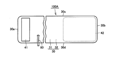
- FIG. 14 shows a plan view when a general cuff 100A is developed.
- a part of the exterior cover 30 is cut away and illustrated, but actually, the exterior cover 30 is continuous in the part. The same applies to FIG. 15 described later.
- the cuff 100 ⁇ / b> A includes an exterior cover 30, an air bag (not shown) included as a fluid bag in the exterior cover 30, a hook-and-loop fastener 41, and a hook-and-loop fastener 42.
- the exterior cover 30 has a front surface 31, a back surface 32, one end 30a, the other end 30b, one side 30c, and the other side 30d.
- the air bag is connected to the air tube 80 while being enclosed in the exterior cover 30.
- the air bag is provided on the one end 30 a side in the longitudinal direction of the exterior cover 30.
- the longitudinal direction referred to here is a direction connecting the one end 30 a and the other end 30 b of the exterior cover 30.
- the hook-and-loop fastener 41 is provided on the surface 31 of the exterior cover 30.
- the hook-and-loop fastener 42 is provided on the back surface 32 of the exterior cover 30. The hook-and-loop fastener 41 and the hook-and-loop fastener 42 can be locked to each other.
- the cuff 100A is placed so that the back surface 32 of the exterior cover 30 and a living body (not shown) face each other (see FIG. 16).
- the cuff 100A is wound around the living body in an annular shape.
- the hook-and-loop fastener 41 and the hook-and-loop fastener 42 are mutually locked, the fastening state with respect to the living body of the outer cover 30 wound in an annular shape is maintained.
- the air bag contained in the exterior cover 30 is fixed to the living body, and blood pressure information can be measured.
- a cuff having a configuration substantially similar to that of the cuff 100A is disclosed in the following Japanese Patent Application Laid-Open No. 2004-166943 (Patent Document 1).
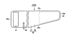
- the width of the outer cover 30 gradually decreases from the one end 30a toward the other end 30b.
- the exterior cover 30 of the cuff 100B is configured such that the width of the exterior cover 30 is narrowed only at the side portion 30d, but is configured such that the width of the exterior cover 30 is narrowed at both the side portion 30c and the side portion 30d. Sometimes it is done.
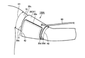
- the other end 30b of the outer cover 30 may be locked in a state of being biased toward the shoulder side.
- the side portion 30c of the exterior cover 30 in the vicinity of the other end portion 30b is disposed so as to protrude from the surface 31 of the exterior cover 30 that is already wound (on the one end portion 30a side) toward the outside (the surface of the upper arm 70). Yes.
- the other end 30b of the exterior cover 30 is locked in a state of being biased toward the shoulder.
- the hook-and-loop fastener 42 may be wound so as to visually overlap the hook-and-loop fastener 41.
- the side portion 30c of the exterior cover 30 in the vicinity of the other end portion 30b is disposed so as to overlap the side portion 30c of the exterior cover 30 that is already wound around the upper arm 70 (on the one end portion 30a side).
- the side portion 30d of the exterior cover 30 in the vicinity of the other end portion 30b is arranged so as to overlap the side portion 30d of the exterior cover 30 that is already wound around the upper arm 70 (on the one end portion 30a side).
- the contact area between the hook-and-loop fastener 41 and the hook-and-loop fastener 42 is reduced by the gap S, the locking force between the hook-and-loop fastener 41 and the hook-and-loop fastener 42 is reduced.
- the air bag cannot be inflated and deflated at a desired pressure, and as a result, the cuff 100A may come off the upper arm 70 during the measurement of the blood pressure value. As a result, the measurement values vary, and it is difficult to measure blood pressure information accurately and stably.
- An object of the present invention is to provide a cuff for a blood pressure information measurement device that can be reliably attached to a measurement site, and a blood pressure information measurement device including the same.
- a cuff for a blood pressure information measurement device has a fluid bag for compressing a living body, a first main surface and a second main surface, and encloses the fluid bag on one end side.
- a second locking member provided in any of the above, the outer cover is wrapped around the living body in an annular shape, and the first locking member and the second locking member are wound around the living body
- a fastening state of the exterior cover with respect to the living body is maintained, and the exterior cover is a portion of the exterior cover that includes a region where the second engagement member is provided.
- the width of the exterior cover is larger than the width of the portion including the region where the Has a first wide portion Kunar, said second locking member has a second wide portion above the than the width of the first locking member width of the second locking member is widened.
- the first wide portion of the exterior cover and the second wide portion of the second locking member are moved from the one end side to the other end side of the outer cover. It has a substantially arcuate shape whose width gradually increases outward in the width direction.
- the first wide portion of the exterior cover and the second wide portion of the second locking member are moved from the one end side to the other end side of the outer cover. It has a shape that spreads on both outer sides in the width direction.
- first wide portion of the exterior cover and the second wide portion of the second locking member may be bent toward the first main surface side or the second main surface side. Is possible.
- the second locking member and a portion of the exterior cover including a region where the second locking member is provided include the first locking surface from the first main surface side.
- the opening part penetrated toward 2 main surface sides is each provided.
- a cuff for a blood pressure information measurement device is provided in a fluid bag for compressing a living body, a first exterior cover containing the fluid bag, and the first exterior cover.
- a connection member that rotatably connects the one end side, and the first exterior cover and the second exterior cover are annularly connected to the living body while being connected to each other by the connection member. The wound and the first locking member and the second locking member hold the wound state of the wound first and second exterior covers to the living body.
- a blood pressure information measurement device includes the blood pressure information measurement device cuff according to any one of the above, an expansion / contraction mechanism that expands / contracts the fluid bag, and a blood pressure information acquisition unit that acquires blood pressure information. .
- a cuff for a blood pressure information measuring device and a blood pressure information measuring device including the same which can be reliably attached to a measurement site.
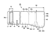
- FIG. 3 is a plan view showing a cuff in the first embodiment.
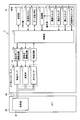
- 3 is a diagram showing functional blocks of a sphygmomanometer according to Embodiment 1.
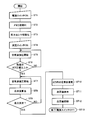
- FIG. 5 is a diagram showing a flow of processing of a sphygmomanometer in the first embodiment.
- FIG. 10 is a plan view showing a cuff in the first modification example of the first embodiment.
- FIG. 10 is a plan view showing a cuff in the second modification example of the first embodiment.
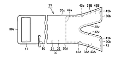
- FIG. 11 is a plan view showing a cuff in the third modification example of the first embodiment.
- FIG. 11 is a plan view showing a cuff in the fourth modification example of the first embodiment.
- FIG. 10 is a plan view showing a cuff in a fifth modification example of the first embodiment.
- FIG. 10 is a plan view showing a cuff in a sixth modification example of the first embodiment.
- FIG. 25 is a plan view showing a cuff in the seventh modification example of the first embodiment.
- FIG. 10 is a plan view showing a cuff in the second embodiment. It is a figure which shows the whole structure of the blood pressure meter in Embodiment 3.
- FIG. It is a top view which shows a general cuff. It is a top view which shows the other general cuff. It is a figure which shows a mode that the general cuff was fastened by the upper arm. It is a figure which shows the other mode that the general cuff was fastened by the upper arm.
- a blood pressure information measuring device cuff and a blood pressure information measuring device including the same according to each embodiment of the present invention will be described below with reference to the drawings.
- a sphygmomanometer cuff that is used by being wound around the upper arm will be described as an example of a cuff for a blood pressure information measurement device.
- a blood pressure information measuring device including a blood pressure information measuring device cuff, a blood pressure meter capable of measuring blood pressure values such as systolic blood pressure values and diastolic blood pressure values using the blood pressure meter cuff will be described.
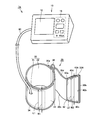
- blood pressure monitor 1 includes a main body 10, a cuff 20, and an air tube 80.
- the main body 10 has a box-shaped housing.
- a display unit 12 and an operation unit 15 are provided on the upper surface of the main body 10.
- the main body 10 is used by being placed on a table or the like during measurement.
- the cuff 20 includes an exterior cover 30, an air bag 34 included as a fluid bag in the exterior cover 30, a hook-and-loop fastener 41 (first locking member), and a hook-and-loop fastener 42 (second locking member). ing.
- the exterior cover 30 has a front surface (first main surface) 31, a back surface (second main surface) 32, one end 30a, the other end 30b, one side 30c, and the other side 30d.
- the exterior cover 30 is configured as a bag-like member by superimposing a member constituting the front surface 31 and a member constituting the back surface 32 and joining the peripheral edges thereof (for example, sewing or welding).
- the cuff 20 is disposed so that the back surface 32 of the exterior cover 30 and a living body such as an upper arm face each other.
- a member sufficiently rich in elasticity is preferably used so that the compression force applied to the upper arm by the expansion of the air bladder 34 is not hindered.
- a member having poor elasticity as compared with the member constituting the back surface 32 side of the exterior cover 30 is used.
- a cloth made of synthetic fibers such as polyamide (PA) and polyester capable of adjusting the size of stretchability relatively easily is used.
- the air bag 34 is connected to the air tube 80.
- the air bag 34 is included on the one end 30 a side in the longitudinal direction of the exterior cover 30.
- the air bag 34 is comprised from a bag-shaped member, and has an expansion / contraction space inside.
- the air bag 34 is preferably configured using a resin sheet.
- the air bag 34 is configured in a bag shape by, for example, superimposing two resin sheets and welding the peripheral edges thereof.
- the material of the resin sheet constituting the air bag 34 is, for example, ethylene-vinyl acetate copolymer (EVA), soft vinyl chloride (PVC), polyurethane (PU), natural rubber (NR), or the like.
- EVA ethylene-vinyl acetate copolymer
- PVC soft vinyl chloride
- PU polyurethane
- NR natural rubber
- the air tube 80 connects the main body 10 configured separately and the air bag 34 included in the cuff 20.
- the air bladder 34 is inflated by injecting fluid from the main body 10 through the air tube 80.
- the air bag 34 contracts when fluid is discharged from the main body 10 through the air tube 80. By the expansion and contraction, the air bag 34 can press a living body such as the upper arm.
- the outer cover 30 may include a curler (not shown) as a curved elastic plate in addition to the air bag 34.
- the curler is generally configured in a substantially cylindrical shape by a flexible member so as to fit a living body. A part of the curler is broken in the cylinder axis direction, and is encased in the exterior cover 30 along the longitudinal direction of the exterior cover 30. Thus, the curler can be elastically deformed in the radial direction when being wound around the living body.
- the curler is disposed outside the air bag 34 (outside the air bag 34 when the cuff 20 is wound around the living body).
- FIG. 2 shows a plan view when the cuff 20 used in the sphygmomanometer 1 in the present embodiment is developed.
- FIG. 2 the air bag (34) contained in the exterior cover 30 is not shown. The same applies to first to seventh modifications of the first embodiment described later and FIGS. 5 to 12 relating to the description of the second embodiment.
- FIG. 2 a part of the exterior cover 30 is broken and illustrated, but the exterior cover 30 is actually continuous in the part. The same applies to FIGS. 5 to 12.
- one side portion 30c of the exterior cover 30 is configured in a substantially linear shape along the longitudinal direction.
- a portion of the exterior cover 30 including the region R1 where the hook-and-loop fastener 41 is provided extends in the longitudinal direction and has a substantially band shape.
- the portion has a width W1.
- the exterior cover 30 is configured such that only the other side portion 30d is curved and spreads outward (downward on the paper surface). As the other side portion 30d of the exterior cover 30 moves from the one end portion 30a side to the other end portion 30b side, the width of the exterior cover 30 in the portion including the region R2 in which the surface fastener 42 is provided in the exterior cover 30. Is configured to gradually widen. Following this configuration, the other side 30d of the exterior cover 30 is configured such that the width of the exterior cover 30 becomes relatively steeply narrowed from the one end 30a side toward the other end 30b side.
- Part of the exterior cover 30 including the region R2 where the hook-and-loop fastener 42 is provided has a width W2.
- the width W2 in a part of the portion including the region R2 where the surface fastener 42 is provided is set wider than the width W1 of the portion of the exterior cover 30 including the region R1 where the surface fastener 41 is provided.
- the exterior cover 30 has a first wide portion 33A that protrudes toward the other side portion 30d.
- the hook-and-loop fastener 41 is provided in a substantially rectangular shape on the surface 31 of the exterior cover 30.
- the hook-and-loop fastener 41 is provided on the one end 30 a side of the exterior cover 30.
- the surface fastener 41 is provided at a substantially central position in the width direction of the exterior cover 30.
- the hook-and-loop fastener 41 has a width L1.
- the hook-and-loop fastener 42 is provided on the back surface 32 of the exterior cover 30.
- the hook-and-loop fastener 42 is provided on the other end 30 b side of the exterior cover 30.
- the surface fastener 42 has one end 42a, the other end 42b, one side 42c, and the other side 42d.
- One side portion 42 c of the hook-and-loop fastener 42 is configured in a straight line substantially parallel to the longitudinal direction of the exterior cover 30.
- the hook-and-loop fastener 42 is configured such that only the other side portion 42d is curved and spreads outward (downward on the paper surface).
- the other side portion 42d of the hook-and-loop fastener 42 is configured such that the width of the hook-and-loop fastener 42 gradually increases from the one end portion 42a side toward the other end portion 42b side.
- the other side portion 42d of the hook-and-loop fastener 42 is configured such that the width of the hook-and-loop fastener 42 becomes relatively steeply narrow in the vicinity of the other end portion 42b from the one end portion 42a side toward the other end portion 42b side.
- the surface fastener 42 has a width L2 in a part thereof.
- the width L2 of a part of the hook-and-loop fastener 42 is set wider than the width L1 of the hook-and-loop fastener 41.
- the hook-and-loop fastener 42 has a second wide portion 43A that protrudes toward the other side portion 42d.
- the cuff 20 When measuring the blood pressure value using the sphygmomanometer 1 having the above configuration, the cuff 20 is placed so that the back surface 32 of the outer cover 30 and the upper arm, for example, face each other.
- the outer cover 30 is wound around the upper arm in a ring shape so that the substantially center position of the air bag 34 (see FIG. 1) in the longitudinal direction and the measurement site are opposed to each other.
- the hook-and-loop fastener 41 and the hook-and-loop fastener 42 are overlapped with each other by being overlapped, and the wound outer cover 30 is held in a fastened state with respect to the living body.
- the air bag contained in the exterior cover 30 is fixed to the living body, and blood pressure information can be measured.
- the main body 10 of the sphygmomanometer 1 includes a control unit 11, a memory unit 13, a power supply unit 14, a pressurizing pump 16a, an exhaust valve 16b, and a pressure sensor 16c. , A pressure pump drive circuit 17a, an exhaust valve drive circuit 17b, and an oscillation circuit 17c.
- the pressurizing pump 16a, the exhaust valve 16b, and the pressure sensor 16c correspond to the air system component 16 in the sphygmomanometer 1.
- the pressurizing pump 16a and the exhaust valve 16b correspond to an inflating / contracting mechanism in the sphygmomanometer 1 for inflating and deflating the air bladder 34.
- the air bag 34 has an expansion / contraction space as a lumen.
- the air bag 34 is connected to each of the pressurization pump 16a, the exhaust valve 16b, and the pressure sensor 16c via an air pipe 80.
- the control unit 11 is composed of, for example, a CPU (Central Processing Unit).
- the control unit 11 controls the entire sphygmomanometer 1.
- the display unit 12 is configured by, for example, an LCD (Liquid Crystal Display).
- the display unit 12 displays measurement results and the like.
- the memory unit 13 includes a processing memory 13a and a data memory 13b.
- the memory unit 13 stores a program for causing the control unit 11 or the like to execute a processing procedure for blood pressure value measurement, or stores a measurement result or the like, using the processing memory 13a and the data memory 13b.
- the power supply unit 14 supplies power as a power source to the control unit 11.
- the operation unit 15 includes a power switch 15a, a measurement switch 15b, a stop switch 15c, and a record call switch 15d.
- the operation unit 15 receives an operation from the switches 15 a to 15 d by a subject or the like and inputs an external command to the control unit 11 or the power supply unit 14.
- the control unit 11 inputs control signals for driving the pressure pump 16a and the exhaust valve 16b to the pressure pump drive circuit 17a and the exhaust valve drive circuit 17b, respectively.
- the control unit 11 inputs a blood pressure value as a measurement result to the memory unit 13 or the display unit 12.
- the control unit 11 includes a blood pressure information acquisition unit (not shown) that acquires the blood pressure value of the subject based on the pressure value detected by the pressure sensor 16c.
- the blood pressure value acquired by the blood pressure information measurement unit is input to the memory unit 13 or the display unit 12 described above as a measurement result.
- the sphygmomanometer 1 may further include an output unit that outputs a blood pressure value as a measurement result to an external device (for example, a PC (Personal Computer) or a printer).
- an external device for example, a PC (Personal Computer) or a printer.
- the output unit for example, a serial communication line or a writing device for various recording media can be used.
- the expansion / contraction operation of the pressurizing pump 16a is controlled by the pressurizing pump drive circuit 17a based on a control signal input from the control unit 11.
- the pressurizing pump 16 a pressurizes the pressure inside the air bladder 34 (hereinafter also referred to as “cuff pressure”) by supplying a fluid such as air to the lumen of the air bladder 34.
- the opening / closing operation of the exhaust valve 16b is controlled by the exhaust valve drive circuit 17b based on a control signal input from the control unit 11.
- the exhaust valve 16b maintains the pressure inside the air bag 34, or opens the lumen of the air bag 34 to the outside to reduce the cuff pressure.
- the pressure sensor 16c inputs an output signal corresponding to the pressure inside the air bladder 34 to the oscillation circuit 17c.
- the oscillation circuit 17c generates a signal having an oscillation frequency corresponding to the signal input from the pressure sensor 16c, and inputs the generated signal to the control unit 11.
- the subject When measuring the blood pressure value, the subject wears the cuff 20 on the upper arm in advance. In this state, the subject operates the operation unit 15 (power switch 15a) provided in the main body 10 to turn on the power source of the sphygmomanometer 1 (step ST1).
- Power from the power supply unit 14 is supplied to the control unit 11 to drive the control unit 11.
- the control unit 11 initializes the memory unit 13 (step ST2).
- Control unit 11 initializes pressure sensor 16c (step ST3).
- the control unit 11 waits for an instruction to start measurement by the subject.
- the subject operates the operation unit 15 (measurement switch 15b) as an instruction to start measurement (step ST4).
- the control unit 11 closes the exhaust valve 16b and drives the pressure pump 16a. Pressurization of the air bag 34 is started (step ST5).
- the cuff pressure of the air bag 34 increases.
- the cuff pressure of the air bag 34 reaches a predetermined cuff pressure or higher necessary for blood pressure measurement (step ST6).
- the control unit 11 stops the pressurizing pump 16a and opens the closed exhaust valve 16b.
- the air in the air bladder 34 is exhausted, and the decompression of the air bladder 34 is gradually started (step ST7).
- the blood pressure value is measured in the process where the cuff pressure is gradually reduced.
- the sphygmomanometer 1 calculates blood pressure values such as systolic blood pressure values and diastolic blood pressure values by the control unit 11 (step ST8).
- the control unit 11 extracts pulse wave information based on the oscillation frequency obtained from the oscillation circuit 17c in the process of gradually reducing the cuff pressure of the air bladder 34.
- the control unit 11 determines a blood pressure value based on the extracted pulse wave information (step ST9).
- the control unit 11 opens the exhaust valve 16b to completely exhaust the air in the air bag 34 (step ST10).
- the control unit 11 displays the blood pressure value as the measurement result on the display unit 12 (step ST11).
- the control unit 11 stores the blood pressure value in the memory unit 13 and records it as data (step ST12).
- the test subject operates the operation unit 15 (power switch 15a) provided on the main body to turn off the blood pressure monitor 1.
- the operation of the sphygmomanometer 1 ends (step ST13).
- the measurement method described above is a so-called decompression measurement method that detects a pulse wave when the air bag 34 is decompressed.
- the measurement method of the sphygmomanometer 1 in the present embodiment is not limited to the decompression measurement method, and a so-called pressurization measurement method that detects a pulse wave when the air bag 34 is pressurized can be employed.
- the cuff 20 is placed so that the back surface 32 of the exterior cover 30 and the upper arm (not shown) of the subject's left arm as a living body face each other.
- the cuff 20 is wound around the upper arm in an annular shape by the subject's right hand so that the substantially center position of the air bag 34 in the longitudinal direction and the measurement site are opposed to each other.
- one end 30 a of the outer cover 30 is sandwiched between the upper arm and the back surface 32 of the outer cover 30.
- the exterior cover 30 is fastened to the upper arm.
- the hook-and-loop fastener 41 and the hook-and-loop fastener 42 are locked to each other to maintain a fastening state with respect to the upper arm of the wound outer cover 30.
- the air bag 34 contained in the exterior cover 30 is fixed to the upper arm, and blood pressure information can be measured.
- the outer cover 30 is provided with a first wide portion 33A, and the hook-and-loop fastener 42 is provided with a second wide portion 43A.
- the side portion (the other side portion 30d) on which the first wide portion 33A and the second wide portion 43A are provided is located on the elbow side (see FIG. 16). Arrange as follows.
- the side portion 30c of the other end portion 30b of the exterior cover 30 may be locked in a state of being biased toward the shoulder side.
- the portion exposed without contacting the hook-and-loop fastener 42 is covered with the second wide portion 43A according to the sphygmomanometer 1 in the present embodiment. .
- the surface fastener 41 and the surface fastener 42 are in contact with each other with a sufficient contact area. By increasing the contact area between the hook-and-loop fastener 41 and the hook-and-loop fastener 42, it is possible to sufficiently secure the locking force between the hook-and-loop fastener 41 and the hook-and-loop fastener 42.
- the air bag 34 can be inflated and deflated at a desired pressure, and the cuff 20 can be prevented from being detached from the living body such as the upper arm during measurement of the blood pressure value. Therefore, according to the cuff 20 and the sphygmomanometer 1 including the cuff 20 in the present embodiment, it is possible to reliably attach to the measurement site, and there is no variation in measured values, and the accuracy is stable. Blood pressure information can be measured.
- the first embodiment and this modification are different in the outer shape of the exterior cover 30 constituting the cuff 21 (see FIG. 5) and the outer shape of the hook-and-loop fastener 42 constituting the cuff 21.
- the portion including the region R1 where the hook-and-loop fastener 41 is provided in the exterior cover 30 in the present modification extends in the longitudinal direction in the same manner as in the first embodiment, and is configured in a substantially band shape.
- the portion has a width W1.
- the one side portion 30c also extends outward (upward on the paper surface). It is configured.
- One side portion 30c of the outer cover 30 has a width of the outer cover 30 in a portion including the region R2 where the surface fastener 42 is provided in the outer cover 30 as it goes from the one end portion 30a side to the other end portion 30b side. Is formed in an arc shape that gradually spreads (upward in the drawing).
- the width of the exterior cover 30 in the portion including the region R2 in which the surface fastener 42 is provided in the exterior cover 30 is formed in an arc shape that gradually spreads (downward on the paper surface).
- Part of the exterior cover 30 including the region R2 where the surface fastener 42 is provided has a width W2 in a part thereof.
- the width W2 in a part including the region R2 where the hook-and-loop fastener 42 is provided is set wider than the width W1 of the portion including the region R1 in the exterior cover 30 as in the first embodiment.
- the exterior cover 30 is not limited to the first wide portion 33 ⁇ / b> A that projects toward the other side portion 30 d, but another first wide portion that projects toward the one side portion 30 c. It has a portion 33B.
- one side portion 42c is also configured to spread outward (upward on the paper surface).
- One side portion 42c of the hook-and-loop fastener 42 is formed in an arc shape so that the width of the hook-and-loop fastener 42 gradually increases from the one end portion 42a side toward the other end portion 42b side.
- the surface fastener 42 has a width L2 in a part thereof.
- the width L2 in a part of the hook-and-loop fastener 42 is set wider than the width L1 in the hook-and-loop fastener 41 as in the first embodiment.
- the hook-and-loop fastener 42 has another second wide portion protruding toward the one side portion 42c in addition to the second wide portion 43A protruding toward the other side portion 42d. It has a portion 43B.
- the exterior cover 30 has a first wide portion 33A and another first wide portion 33B, and the hook-and-loop fastener 42 has a second wide portion 43A and another second wide portion 43B.
- the cuff 20 in the first embodiment is provided on the side where the first wide portion 33A and the second wide portion 43A are provided (the side of the exterior cover 30) in order to bring the surface fastener 41 and the surface fastener 42 into sufficient contact with each other.
- the part 30d side needs to be wound so as to be located on the elbow side. Therefore, the sphygmomanometer including the cuff 20 in the first embodiment can be used by being wound only on one arm (for example, the left arm).
- the exterior cover 30 in this modification is provided with the first wide portion 33A and the second wide portion 43A on the side portion 30d side of the exterior cover 30, and the other first wide portion 33B and the side portion 30c side of the exterior cover 30.
- Another second wide portion 43B is provided. Therefore, the sphygmomanometer including the cuff 21 in the present modification can be used regardless of which arm (right arm and left arm) is wound.
- the first wide portions 33A and 33B in the exterior cover 30 and the second wide portions 43A and 43B in the hook-and-loop fastener 42 gradually increase in width from the one end 30a side to the other end 30b side of the exterior cover 30. It is configured in an arc shape that expands.
- the side portion 30d side of the exterior cover 30 is placed near the elbow (see FIG. 16).
- the arc-shaped configuration of the exterior cover 30 can be used during the winding of the cuff 21 around the upper arm.
- the side portions 30d of the exterior cover 30 it is possible to overlap the side portions 30d that are not yet wound around the upper arm along the side portions 30d that are already wound around the upper arm. Become.
- the side portions 30d When the side portions 30d are overlapped as a whole, the side portions 30d form one circle around the upper arm on substantially the same plane. It is possible to give a visual sense of stability to the user of the sphygmomanometer provided with the cuff 21.
- the first modified example and the present modified example are different in the exterior cover 30 constituting the cuff 22 (see FIG. 6) and the hook-and-loop fastener 42 constituting the cuff 22.
- the exterior cover 30 constituting the cuff 22 in the present modification is configured such that the first wide portion 33A and the first wide portion 33B can be folded back to the front surface 31 side or the back surface 32 side, respectively.
- the hook-and-loop fastener 42 constituting the cuff 22 in the present modification is configured to be able to fold the second wide portion 43A and the second wide portion 43B to the front surface 31 side or the back surface 32 side, respectively. It has become.
- the case is stored when the sphygmomanometer including the cuff 22 is stored.
- the size of can be reduced.
- the first modification and the present modification are different in the exterior cover 30 constituting the cuff 23 (see FIG. 7) and the hook-and-loop fastener 42 constituting the cuff 23.
- the portion including the area where the hook-and-loop fastener 42 is provided is substantially V-shaped from the other end 30b side to the one end 30a side of the exterior cover 30.
- a notch 30v is provided.
- the notch 30v is positioned at the approximate center of the exterior cover 30 in the width direction.
- the notch 30v is provided from the other end 30b side of the exterior cover 30 toward the one end 30a side.
- the hook-and-loop fastener 42 constituting the cuff 23 in this modification is also provided with a substantially V-shaped notch 42v from the other end 42b toward the one end 42a.
- the notch 42v is located substantially at the center in the width direction of the hook-and-loop fastener 42, and is provided from the other end portion 42b side toward the one end portion 42a side.
- the surface fastener 41 and the surface fastener 42 are locked after the cuff 21 in the first modified example (FIG. 5) is annularly wound around a living body such as the upper arm, the other end portion 30b side of the exterior cover 30 is provided. In some cases, wrinkles may occur in the width direction. According to the cuff 23 in this modification, it is possible to prevent wrinkles from occurring in the width direction on the other end 30b side of the exterior cover 30 by providing the notch 30v and the notch 42v. Become.
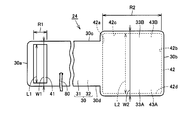
- the first modified example and the present modified example are different in the outer shape of the exterior cover 30 constituting the cuff 24 (see FIG. 8) and the outer shape of the hook-and-loop fastener 42 constituting the cuff 24.
- the portion including the region R1 where the hook and loop fastener 41 is provided in the exterior cover 30 in the present modified example extends in the longitudinal direction in the same manner as in the first modified example, and is configured in a substantially band shape.
- the portion has a width W1.
- the outer shape of the part including the region R2 in which the hook and loop fastener 42 is provided in the exterior cover 30 in the present modification is configured to be a substantially rectangular shape with four rounded corners.
- the portion including the region R2 where the hook-and-loop fastener 42 is provided in the exterior cover 30 has a width W2 in a part thereof, as in the first modification.
- the width W2 at a part of the portion including the region R2 where the hook-and-loop fastener 42 is provided is set wider than the width W1 of the portion including the region R1 in the exterior cover 30 as in the first modification.
- the exterior cover 30 includes a first wide portion 33A that protrudes toward the other side portion 30d and another first wide portion 33B that protrudes toward the one side portion 30c. And have.
- the outer shape of the hook-and-loop fastener 42 in this modification is configured in a substantially rectangular shape with four rounded corners.
- the hook-and-loop fastener 42 has a width L2 in a part thereof, as in the first modification.
- the width L2 in a part of the hook-and-loop fastener 42 is set wider than the width L1 in the hook-and-loop fastener 41 as in the first modification.
- the hook-and-loop fastener 42 includes a second wide portion 43A protruding toward the other side portion 42d and another second wide portion 43B protruding toward the one side portion 42c. And have.
- the first wide portions 33A and 33B are provided in the exterior cover 30 and the second wide portions 43A and 43B are provided in the hook-and-loop fastener 42, as in the first modified example. Even when the other end 30b of the exterior cover 30 is locked in a state of being biased toward the shoulder, the hook-and-loop fastener 41 and the hook-and-loop fastener 42 can contact each other with a sufficient contact area.
- the cuff 24 and the sphygmomanometer including the cuff 24 in the present modification it is possible to reliably attach to the measurement site, and the blood pressure information can be measured accurately and stably without any variation in the measurement value. It becomes possible to do.
- the sphygmomanometer provided with the cuff 24 in this modification can be used regardless of which arm (right arm and left arm) is wound.
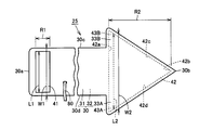
- the first modified example and the present modified example differ in the outer shape of the exterior cover 30 constituting the cuff 25 (see FIG. 9) and the outer shape of the hook-and-loop fastener 42 constituting the cuff 25.
- the portion including the region R1 where the hook-and-loop fastener 41 is provided in the exterior cover 30 in the present modified example extends in the longitudinal direction in the same manner as in the first modified example, and is configured in a substantially band shape.
- the portion has a width W1.
- the portion of the exterior cover 30 in this modification including the region R2 where the hook-and-loop fastener 42 is provided is configured in a substantially isosceles triangle shape having a bottom on the one end 30a side of the exterior cover 30.
- the portion including the region R2 where the hook-and-loop fastener 42 is provided in the exterior cover 30 has a width W2 in a part thereof, as in the first modification.
- the width W2 at a part of the portion including the region R2 where the hook-and-loop fastener 42 is provided is set wider than the width W1 of the portion including the region R1 in the exterior cover 30 as in the first modification.
- the exterior cover 30 includes a first wide portion 33A that protrudes toward the other side portion 30d and another first wide portion 33B that protrudes toward the one side portion 30c. And have.
- the hook-and-loop fastener 42 in the present modification is configured in a substantially isosceles triangle shape having a base on the one end 42a side of the hook-and-loop fastener 42.
- the hook-and-loop fastener 42 has a width L2 in a part thereof, as in the first modification.
- the width L2 in a part of the hook-and-loop fastener 42 is set wider than the width L1 in the hook-and-loop fastener 41 as in the first modification.
- the hook-and-loop fastener 42 includes a second wide portion 43A protruding toward the other side portion 42d and another second wide portion 43B protruding toward the one side portion 42c. And have.
- the first wide portions 33A and 33B are provided in the exterior cover 30 and the second wide portions 43A and 43B are provided in the hook-and-loop fastener 42, as in the first modified example. Even when the other end 30b of the exterior cover 30 is locked in a state of being biased toward the shoulder, the hook-and-loop fastener 41 and the hook-and-loop fastener 42 can contact each other with a sufficient contact area.
- the cuff 25 and the sphygmomanometer including the cuff 25 in the present modification it is possible to reliably attach to the measurement site, and the blood pressure information can be measured accurately and stably without any variation in the measurement value. It becomes possible to do.
- the sphygmomanometer including the cuff 25 in the present modification can be used regardless of which arm (right arm and left arm) is wound around.
- the first modified example and the present modified example differ in the outer shape of the exterior cover 30 constituting the cuff 26 (see FIG. 10) and the outer shape of the hook-and-loop fastener 42 constituting the cuff 26.
- the portion including the region R1 where the hook-and-loop fastener 41 is provided in the exterior cover 30 in the present modified example extends in the longitudinal direction in the same manner as in the first modified example, and is configured in a substantially band shape.
- the portion has a width W1.
- the portion including the region R2 where the hook-and-loop fastener 42 is provided is configured in a straight line parallel to the width direction in the portion on the one end 30a side, and the other portion.
- the first end portion 30a is continuous with the portion on the one end portion 30a side and is formed in a substantially elliptical shape toward the other end portion 30b side.
- the portion including the region R2 where the hook-and-loop fastener 42 is provided in the exterior cover 30 has a width W2 in a part thereof, as in the first modification.
- the width W2 at a part of the portion including the region R2 where the hook-and-loop fastener 42 is provided is set wider than the width W1 of the portion including the region R1 in the exterior cover 30 as in the first modification.
- the exterior cover 30 includes a first wide portion 33A that protrudes toward the other side portion 30d and another first wide portion 33B that protrudes toward the one side portion 30c. And have.
- the hook-and-loop fastener 42 in this modification is configured in a straight line so as to be parallel to the width direction in the portion on the one end 42a side of the hook-and-loop fastener 42, and is continuous with the portion on the one end 42a side in the other portions. It is comprised in the substantially elliptical shape toward the other end part 42b side.
- the hook-and-loop fastener 42 has a width L2 in a part thereof, as in the first modification.
- the width L2 in a part of the hook-and-loop fastener 42 is set wider than the width L1 in the hook-and-loop fastener 41 as in the first modification.
- the hook-and-loop fastener 42 includes a second wide portion 43A protruding toward the other side portion 42d and another second wide portion 43B protruding toward the one side portion 42c. And have.
- the first wide portions 33A and 33B are provided in the exterior cover 30 and the second wide portions 43A and 43B are provided in the hook-and-loop fastener 42, as in the first modification. Even when the other end 30b of the exterior cover 30 is locked in a state of being biased toward the shoulder, the hook-and-loop fastener 41 and the hook-and-loop fastener 42 can contact each other with a sufficient contact area.
- the cuff 26 and the sphygmomanometer including the cuff 26 in the present modification it is possible to reliably attach the measurement site, and the blood pressure information can be measured accurately and stably without any variation in the measurement value. It becomes possible to do.
- the sphygmomanometer provided with the cuff 26 in this modification can be used regardless of which arm (right arm and left arm) is wound around.
- the sixth modification differs from the present modification in the shape of the exterior cover 30 constituting the cuff 27 (see FIG. 11) and the shape of the hook-and-loop fastener 42 constituting the cuff 27.
- an opening 30H penetrating from the front surface 31 side toward the back surface 32 side is provided in a portion including a region where the surface fastener 42 is provided.
- the opening 42H penetrating from the front surface 31 side to the back surface 32 side is also provided in the hook-and-loop fastener 42 constituting the cuff 27 in this modification.
- the opening 30H of the exterior cover 30 and the opening 42H of the hook-and-loop fastener 42 have substantially the same shape in plan view and are arranged at substantially the same position.
- the opening 42H and the opening 30H are formed in a substantially elliptical shape extending in the longitudinal direction.
- the opening 30H and the opening 42H are located at the approximate center in the width direction of the hook-and-loop fastener 42 and the approximate center in the longitudinal direction.
- the exterior cover 30 and the surface fastener 42 can be easily expanded and contracted in the longitudinal direction. Using the expansion and contraction, the cuff 27 can be flexibly wound around various biological shapes.
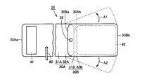
- the cuff 28 in the present embodiment includes air that is contained as a fluid bag in the first exterior cover 30A, the second exterior cover 30B, and the first exterior cover 30A.
- a bag (not shown), a hook-and-loop fastener 41 (first locking member), a hook-and-loop fastener 42 (second locking member), and a connection member 38 are provided.
- the first exterior cover 30A has a front surface 31A, a back surface 32A, one end 30Aa, and the other end 30Ab.
- the first exterior cover 30A extends in the longitudinal direction and is formed in a substantially strip shape.
- the air bag is contained in the first exterior cover 30A as described above. The air bag is connected to the air tube 80.
- the hook-and-loop fastener 41 is provided in a substantially rectangular shape on the surface 31A of the first exterior cover 30A.
- the hook-and-loop fastener 41 is provided on the one end 30Aa side of the first exterior cover 30A.
- the hook-and-loop fastener 41 is provided at a substantially central position in the width direction of the first exterior cover 30A.
- the second exterior cover 30B has a front surface 31B, a back surface 32B, one end 30Ba, and the other end 30Bb.
- the second exterior cover 30B extends in the longitudinal direction and is formed in a substantially band shape.
- the hook-and-loop fastener 42 is provided in a substantially rectangular shape on the back surface 32B of the second exterior cover 30B so as to cover substantially the entire back surface 32B.
- the connecting member 38 rotatably connects the other end 30Ab side of the first exterior cover 30A and the one end 30Ba side of the second exterior cover 30B.
- the connection member 38 allows the second exterior cover 30B to rotate in the direction indicated by the arrow A1 and the direction indicated by the arrow A2 with respect to the first exterior cover 30A.
- the connecting member 38 is formed in, for example, a cylinder extending in the direction perpendicular to the paper surface.
- the connecting member 38 has a flange shape that protrudes in the cylindrical diameter direction at both ends (in the direction perpendicular to the paper surface) in order to maintain the connection between the first exterior cover 30A and the second exterior cover 30B. It is preferable that a protrusion is provided.
- the cuff 28 When measuring a blood pressure value using a sphygmomanometer having the above-described configuration, the cuff 28 has a back surface 32A of the first exterior cover 30A (and a back surface 32B of the second exterior cover 30B), and an upper arm as a living body, for example. Are placed so as to face each other.
- the first and second exterior covers 30A and 30B are wound around the upper arm in an annular shape.
- the hook-and-loop fastener 41 and the hook-and-loop fastener 42 are locked to each other by being overlapped, and hold the fastened state with respect to the upper arms of the wound first and second exterior covers 30A and 30B.
- the air bag is fixed to the living body, and blood pressure information can be measured.
- the first exterior cover 30A and the second exterior cover 30B are rotatably connected.
- the exposed portion of the hook-and-loop fastener 41 that is not in contact with the hook-and-loop fastener 42 is covered with the hook-and-loop fastener 42 by rotating the second exterior cover 30B.
- the surface fastener 41 and the surface fastener 42 are in contact with each other with a sufficient contact area. By increasing the contact area between the hook-and-loop fastener 41 and the hook-and-loop fastener 42, it is possible to sufficiently secure the locking force between the hook-and-loop fastener 41 and the hook-and-loop fastener 42.
- the air bag can be inflated and deflated at a desired pressure, and the cuff 28 can be prevented from being detached from the living body such as the upper arm during measurement of the blood pressure value.
- the cuff 28 and the sphygmomanometer including the cuff 28 according to the present embodiment it is possible to reliably attach to the measurement site, and there is no variation in the measurement value. It becomes possible to measure.
- the first exterior cover 30A and the second exterior cover 30B are connected so as to be rotatable in both directions indicated by arrows A1 and A2. Therefore, the sphygmomanometer provided with the cuff 28 in the present embodiment is used by being wound around any of the arms (right arm and left arm) by rotating the second exterior cover 30B. A sufficient locking force with the fastener 42 can be secured.
- the cuff 29 in the present embodiment includes an exterior cover 30, an air bag 34 included as a fluid bag in the exterior cover 30, and a hook-and-loop fastener 41 (first locking member). And a hook-and-loop fastener 42 (second locking member) and an annular ring 36.
- the one side part 30c of the exterior cover 30 is comprised in the substantially linear form along the longitudinal direction.
- surface fastener 41 is provided among the exterior covers 30 is extended in the longitudinal direction, and is comprised by the substantially strip
- the portion has a width W1.
- the exterior cover 30 is configured such that only the other side 30d is curved and spreads outward (upward on the paper surface).
- the other side portion 30d of the exterior cover 30 has a width of the exterior cover 30 in a portion including the region where the surface fastener 42 is provided in the exterior cover 30 as it goes from the one end portion 30a side to the other end portion 30b side. It is configured to gradually widen.
- Part of the exterior cover 30 including the area where the hook-and-loop fastener 42 is provided has a width W2 in a part thereof.
- the width W2 of a part including the area where the surface fastener 42 is provided is set wider than the width W1 of the part including the area where the surface fastener 41 is provided in the exterior cover 30.
- the exterior cover 30 has a first wide portion 33A that protrudes toward the other side portion 30d.
- the hook-and-loop fastener 41 is provided in a substantially rectangular shape on the surface 31 of the exterior cover 30.
- the hook-and-loop fastener 41 is provided between the one end 30 a and the other end 30 b in the longitudinal direction of the exterior cover 30.
- the surface fastener 41 is provided at a substantially central position in the width direction of the exterior cover 30.
- the hook-and-loop fastener 41 has a width L1.
- the hook-and-loop fastener 42 is provided on the surface 31 of the exterior cover 30 similarly to the hook-and-loop fastener 41.
- the hook-and-loop fastener 42 is provided on the other end 30 b side of the exterior cover 30.
- the surface fastener 42 has one end 42a, the other end 42b, one side 42c, and the other side 42d.
- One side portion 42 c of the hook-and-loop fastener 42 is configured in a straight line substantially parallel to the longitudinal direction of the exterior cover 30.
- the hook-and-loop fastener 42 is configured such that only the other side portion 42d is curved and spreads outward (upward on the paper surface).
- the other side portion 42d of the hook-and-loop fastener 42 is configured such that the width of the hook-and-loop fastener 42 gradually increases from the one end portion 42a side toward the other end portion 42b side.
- the surface fastener 42 has a width L2 in a part thereof.
- the width L2 of a part of the hook-and-loop fastener 42 is set wider than the width L1 of the hook-and-loop fastener 41.
- the hook-and-loop fastener 42 has a second wide portion 43A that protrudes toward the other side portion 42d.
- the annular ring 36 is attached to the one end 30 a side of the exterior cover 30.
- the annular ring 36 is attached to the exterior cover 30 by inserting a portion on the one end 30a side of the exterior cover 30 into the annular ring 36, folding it back, and stitching it.
- the annular ring 36 is made of, for example, a metal member that hardly causes friction with the exterior cover 30 and has an insertion hole through which the portion on the other end 30b side of the exterior cover 30 can be inserted.
- the exterior cover 30 is maintained in an annular shape by inserting the other end 30b of the exterior cover 30 into the insertion hole of the annular ring 36 attached in the vicinity of the one end 30a of the exterior cover 30.
- the portion of the exterior cover 30 on the other end 30b side is directed toward the annular ring 36 along the circumferential direction of the annularly formed portion of the exterior cover 30, and is folded back with the annular ring 36 as a base point.
- the upper arm (not shown) of the subject's left arm is inserted into the outer cover 30 formed in an annular shape.
- the exterior cover 30 is fastened to the upper arm by pulling the other end 30b of the exterior cover 30 away from the annular ring 36 by the right hand of the subject.
- the hook-and-loop fastener 41 and the hook-and-loop fastener 42 are engaged with each other to maintain a fastening state with respect to the upper arm of the wound outer cover 30.
- the air bag contained in the exterior cover 30 is fixed to the upper arm, and blood pressure information can be measured.
- the outer cover 30 is provided with a first wide portion 33A, and the hook-and-loop fastener 42 is provided with a second wide portion 43A.
- the side portion on the side where the first wide portion 33A and the second wide portion 43A are provided is disposed so as to be located on the elbow side.
- the hook-and-loop fastener 41 and the hook-and-loop fastener 42 are in contact with each other with a sufficient contact area by providing the hook-and-loop fastener 42 with the second wide portion 43A.
- the air bag 34 can be inflated and deflated at a desired pressure, and the cuff 29 can be prevented from being detached from the living body such as the upper arm during measurement of the blood pressure value. Therefore, according to the cuff 29 and the sphygmomanometer 1a including the cuff 29 according to the present embodiment, it is possible to reliably attach the measurement site, and there is no variation in the measurement value, and the accuracy is stable. Blood pressure information can be measured.
- each configuration can be appropriately combined.
- the second embodiment and the third embodiment it is possible to appropriately combine the configurations (technical ideas).
- the configurations in the first to third embodiments can be applied to a so-called wrist-type sphygmomanometer in which a cuff is attached to the wrist when measuring a blood pressure value and a sphygmomanometer cuff provided therein.
- the configurations in the first to third embodiments can be applied to a so-called ankle-type sphygmomanometer in which a cuff is attached to an ankle when measuring a blood pressure value, and a sphygmomanometer cuff provided in the so-called ankle-type sphygmomanometer. .
- the configurations in the first to third embodiments exemplify a case where the present invention is applied to a sphygmomanometer capable of measuring blood pressure values such as systolic blood pressure values and diastolic blood pressure values, and a sphygmomanometer cuff provided therein.
- a sphygmomanometer capable of measuring blood pressure values such as systolic blood pressure values and diastolic blood pressure values
- a sphygmomanometer cuff provided therein.
- the present invention is not particularly limited to this.
- the configurations in the first to third embodiments include blood pressure information other than blood pressure values such as systolic blood pressure value and diastolic blood pressure value (for example, mean blood pressure value, pulse wave, pulse, AI (Augmentation Index) value) Etc.) and a cuff for a blood pressure information measuring device provided in the blood pressure information measuring device.
- blood pressure information other than blood pressure values such as systolic blood pressure value and diastolic blood pressure value (for example, mean blood pressure value, pulse wave, pulse, AI (Augmentation Index) value) Etc.) and a cuff for a blood pressure information measuring device provided in the blood pressure information measuring device.
Landscapes
- Health & Medical Sciences (AREA)
- Life Sciences & Earth Sciences (AREA)
- Cardiology (AREA)
- Vascular Medicine (AREA)
- Engineering & Computer Science (AREA)
- Medical Informatics (AREA)
- Physics & Mathematics (AREA)
- Ophthalmology & Optometry (AREA)
- Biophysics (AREA)
- Pathology (AREA)
- Dentistry (AREA)
- Biomedical Technology (AREA)
- Heart & Thoracic Surgery (AREA)
- Physiology (AREA)
- Molecular Biology (AREA)
- Surgery (AREA)
- Animal Behavior & Ethology (AREA)
- General Health & Medical Sciences (AREA)
- Public Health (AREA)
- Veterinary Medicine (AREA)
- Measuring Pulse, Heart Rate, Blood Pressure Or Blood Flow (AREA)
Abstract
Priority Applications (4)
| Application Number | Priority Date | Filing Date | Title |
|---|---|---|---|
| CN201180011279.8A CN102770065B (zh) | 2010-02-26 | 2011-02-04 | 血压信息测定装置用袖带及具有该袖带的血压信息测定装置 |
| DE112011100686T DE112011100686T5 (de) | 2010-02-26 | 2011-02-04 | Blutdruckinformationen-Messgerät-Manschette und damit ausgestattetes Blutdruckinformationen-Messgerät |
| RU2012141056/14A RU2562851C2 (ru) | 2010-02-26 | 2011-02-04 | Манжета устройства измерения для оценки кровяного давления и устройство измерения для оценки кровяного давления, снабженное упомянутой манжетой |
| US13/592,833 US9788736B2 (en) | 2010-02-26 | 2012-08-23 | Blood pressure information measurement device cuff and blood pressure information measurement device provided therewith |
Applications Claiming Priority (2)
| Application Number | Priority Date | Filing Date | Title |
|---|---|---|---|
| JP2010-043043 | 2010-02-26 | ||
| JP2010043043A JP5494008B2 (ja) | 2010-02-26 | 2010-02-26 | 血圧情報測定装置用カフおよびこれを備えた血圧情報測定装置 |
Related Child Applications (1)
| Application Number | Title | Priority Date | Filing Date |
|---|---|---|---|
| US13/592,833 Continuation US9788736B2 (en) | 2010-02-26 | 2012-08-23 | Blood pressure information measurement device cuff and blood pressure information measurement device provided therewith |
Publications (1)
| Publication Number | Publication Date |
|---|---|
| WO2011105197A1 true WO2011105197A1 (fr) | 2011-09-01 |
Family
ID=44506615
Family Applications (1)
| Application Number | Title | Priority Date | Filing Date |
|---|---|---|---|
| PCT/JP2011/052390 Ceased WO2011105197A1 (fr) | 2010-02-26 | 2011-02-04 | Brassard pour dispositif de mesure d'informations de pression sanguine et dispositif de mesure d'informations de pression sanguine pourvu d'un tel brassard |
Country Status (6)
| Country | Link |
|---|---|
| US (1) | US9788736B2 (fr) |
| JP (1) | JP5494008B2 (fr) |
| CN (1) | CN102770065B (fr) |
| DE (1) | DE112011100686T5 (fr) |
| RU (1) | RU2562851C2 (fr) |
| WO (1) | WO2011105197A1 (fr) |
Cited By (1)
| Publication number | Priority date | Publication date | Assignee | Title |
|---|---|---|---|---|
| US20160029910A1 (en) * | 2013-03-07 | 2016-02-04 | Omron Healthcare Co., Ltd. | Blood pressure measurement cuff and method for manufacturing blood pressure measurement cuff |
Families Citing this family (7)
| Publication number | Priority date | Publication date | Assignee | Title |
|---|---|---|---|---|
| US9986919B2 (en) | 2011-06-21 | 2018-06-05 | Masimo Corporation | Patient monitoring system |
| US9532722B2 (en) | 2011-06-21 | 2017-01-03 | Masimo Corporation | Patient monitoring system |
| WO2015020911A2 (fr) | 2013-08-05 | 2015-02-12 | Cercacor Laboratories, Inc. | Moyen de surveillance de la pression sanguine avec ensemble soupape-chambre |
| USD879298S1 (en) * | 2017-12-27 | 2020-03-24 | Sky Labs Inc. | Charging holder for sphygmomanometer |
| CN111248974B (zh) * | 2020-03-30 | 2025-04-18 | 广东乐心医疗电子股份有限公司 | 一种袖带及血压计 |
| JP7834493B2 (ja) * | 2022-02-07 | 2026-03-24 | オムロンヘルスケア株式会社 | 血圧測定用カフ |
| TWI900269B (zh) * | 2024-10-01 | 2025-10-01 | 豪展醫療科技股份有限公司 | 可更換式排氣管件、安裝該排氣管件之血壓計及其排氣方法 |
Citations (3)
| Publication number | Priority date | Publication date | Assignee | Title |
|---|---|---|---|---|
| JP3071616U (ja) * | 2000-03-09 | 2000-09-14 | 日本コーリン株式会社 | 血圧測定用カフ |
| WO2007119482A1 (fr) * | 2006-04-12 | 2007-10-25 | Omron Healthcare Co., Ltd. | Ballonet de sphygmomanomètre |
| JP2008029684A (ja) * | 2006-07-31 | 2008-02-14 | Mitsuo Iino | マンシェットカバーおよび同マンシェットカバーを備えたマンシェット |
Family Cites Families (14)
| Publication number | Priority date | Publication date | Assignee | Title |
|---|---|---|---|---|
| US3765405A (en) * | 1971-10-29 | 1973-10-16 | Minnesota Mining & Mfg | Sphygmomanometer cuff |
| JPS55113437A (en) * | 1979-02-07 | 1980-09-02 | Nippon Colleen Kk | Cuff device in blood pressure measuring system |
| US4901732A (en) * | 1988-01-15 | 1990-02-20 | Williams Richard B | Delta cuff |
| US5101830A (en) * | 1990-12-11 | 1992-04-07 | Cas Medical Systems, Inc. | Blood pressure cuff and to a method of making the same |
| US5626142A (en) * | 1995-05-05 | 1997-05-06 | Marks; Lloyd A. | Multiple cuff blood pressure system |
| ATE248553T1 (de) * | 1995-11-21 | 2003-09-15 | Disetronic Licensing Ag | Manschette für blutdruckmessgerät |
| RU3868U1 (ru) * | 1996-02-26 | 1997-04-16 | Акционерное общество закрытого типа "Монолит" | Манжета для измерителя артериального давления |
| US6149600A (en) * | 1998-05-08 | 2000-11-21 | Poorman-Ketchum; Rebekah | Blood pressure measuring device |
| US6489004B1 (en) * | 2000-11-03 | 2002-12-03 | Kimberly-Clark Worldwide, Inc. | Hook and loop fastener having an increased coefficient of friction |
| JP3949563B2 (ja) | 2002-11-19 | 2007-07-25 | 日本精密測器株式会社 | 折返し式カフ |
| RU2366357C2 (ru) * | 2004-12-06 | 2009-09-10 | ООО "ПКТИтрансстрой" | Манжета сфигмоманометра, пресс-форма для ее изготовления и способ ее изготовления |
| JP4595526B2 (ja) * | 2004-12-20 | 2010-12-08 | オムロンヘルスケア株式会社 | 血圧計用カフおよび血圧計 |
| DE102007037770B4 (de) * | 2007-08-10 | 2017-01-05 | Drägerwerk AG & Co. KGaA | Blutdruckmanschette für nicht-invasive Blutdruckmessung |
| JP5217746B2 (ja) * | 2008-08-01 | 2013-06-19 | オムロンヘルスケア株式会社 | 血圧測定装置 |
-
2010
- 2010-02-26 JP JP2010043043A patent/JP5494008B2/ja active Active
-
2011
- 2011-02-04 DE DE112011100686T patent/DE112011100686T5/de active Pending
- 2011-02-04 WO PCT/JP2011/052390 patent/WO2011105197A1/fr not_active Ceased
- 2011-02-04 RU RU2012141056/14A patent/RU2562851C2/ru active
- 2011-02-04 CN CN201180011279.8A patent/CN102770065B/zh active Active
-
2012
- 2012-08-23 US US13/592,833 patent/US9788736B2/en not_active Expired - Fee Related
Patent Citations (3)
| Publication number | Priority date | Publication date | Assignee | Title |
|---|---|---|---|---|
| JP3071616U (ja) * | 2000-03-09 | 2000-09-14 | 日本コーリン株式会社 | 血圧測定用カフ |
| WO2007119482A1 (fr) * | 2006-04-12 | 2007-10-25 | Omron Healthcare Co., Ltd. | Ballonet de sphygmomanomètre |
| JP2008029684A (ja) * | 2006-07-31 | 2008-02-14 | Mitsuo Iino | マンシェットカバーおよび同マンシェットカバーを備えたマンシェット |
Cited By (3)
| Publication number | Priority date | Publication date | Assignee | Title |
|---|---|---|---|---|
| US20160029910A1 (en) * | 2013-03-07 | 2016-02-04 | Omron Healthcare Co., Ltd. | Blood pressure measurement cuff and method for manufacturing blood pressure measurement cuff |
| US11478161B2 (en) * | 2013-03-07 | 2022-10-25 | Omron Healthcare Co., Ltd. | Blood pressure measurement cuff and method for manufacturing blood pressure measurement cuff |
| US11596318B2 (en) | 2013-03-07 | 2023-03-07 | Omron Healthcare Co., Ltd. | Blood pressure measurement cuff and method for manufacturing blood pressure measurement cuff |
Also Published As
| Publication number | Publication date |
|---|---|
| RU2562851C2 (ru) | 2015-09-10 |
| CN102770065A (zh) | 2012-11-07 |
| US9788736B2 (en) | 2017-10-17 |
| DE112011100686T5 (de) | 2013-03-21 |
| JP5494008B2 (ja) | 2014-05-14 |
| US20120316449A1 (en) | 2012-12-13 |
| CN102770065B (zh) | 2014-07-09 |
| RU2012141056A (ru) | 2014-04-10 |
| JP2011177276A (ja) | 2011-09-15 |
Similar Documents
| Publication | Publication Date | Title |
|---|---|---|
| JP5556244B2 (ja) | 血圧情報測定装置用カフおよびこれを備えた血圧情報測定装置 | |
| JP5494008B2 (ja) | 血圧情報測定装置用カフおよびこれを備えた血圧情報測定装置 | |
| JP4665757B2 (ja) | 血圧計用カフおよびこれを備えた血圧計 | |
| JP5169552B2 (ja) | 血圧情報測定装置用カフおよびこれを備えた血圧情報測定装置 | |
| JP5633447B2 (ja) | 血圧情報測定装置用カフの製造方法 | |
| JP4742576B2 (ja) | 血圧計用カフおよびこれを備えた血圧計 | |
| TWI494080B (zh) | 血壓資訊測量裝置用壓脈帶及備有壓脈帶之血壓資訊測量裝置 | |
| CN101522097B (zh) | 血压计用袖带和血压计 | |
| JP2006218178A (ja) | 血圧計用カフおよび血圧計 | |
| JP2006212282A (ja) | 血圧計用カフおよびその製造方法ならびに血圧計 | |
| WO2007119482A1 (fr) | Ballonet de sphygmomanomètre | |
| JP6852446B2 (ja) | 血圧情報測定装置 | |
| JP2012200508A (ja) | 血圧情報測定装置用カフおよびこれを備えた血圧情報測定装置 | |
| JP3171697U (ja) | 血圧情報測定装置用カフおよびこれを備えた血圧情報測定装置 | |
| JP6357934B2 (ja) | 血圧測定用カフおよびその装着方法 | |
| JP2006255097A (ja) | 血圧計用カフおよび血圧計 | |
| JP3168376U (ja) | 血圧情報測定装置用カフおよびこれを備えた血圧情報測定装置 | |
| JP3174765U (ja) | 血圧計用カフ | |
| JP3174209U (ja) | 血圧情報測定装置用カフおよびこれを備えた血圧情報測定装置 | |
| WO2018150749A1 (fr) | Brassard pour dispositif de mesure d'informations de pression artérielle |
Legal Events
| Date | Code | Title | Description |
|---|---|---|---|
| WWE | Wipo information: entry into national phase |
Ref document number: 201180011279.8 Country of ref document: CN |
|
| 121 | Ep: the epo has been informed by wipo that ep was designated in this application |
Ref document number: 11747161 Country of ref document: EP Kind code of ref document: A1 |
|
| WWE | Wipo information: entry into national phase |
Ref document number: 112011100686 Country of ref document: DE Ref document number: 1120111006861 Country of ref document: DE |
|
| WWE | Wipo information: entry into national phase |
Ref document number: 2012141056 Country of ref document: RU |
|
| 122 | Ep: pct application non-entry in european phase |
Ref document number: 11747161 Country of ref document: EP Kind code of ref document: A1 |