WO2011105199A1 - 工作機械及び加工液供給装置、並びに加工液 - Google Patents
工作機械及び加工液供給装置、並びに加工液 Download PDFInfo
- Publication number
- WO2011105199A1 WO2011105199A1 PCT/JP2011/052450 JP2011052450W WO2011105199A1 WO 2011105199 A1 WO2011105199 A1 WO 2011105199A1 JP 2011052450 W JP2011052450 W JP 2011052450W WO 2011105199 A1 WO2011105199 A1 WO 2011105199A1
- Authority
- WO
- WIPO (PCT)
- Prior art keywords
- water
- oil
- machining
- machining fluid
- homogenizer
- Prior art date
- Legal status (The legal status is an assumption and is not a legal conclusion. Google has not performed a legal analysis and makes no representation as to the accuracy of the status listed.)
- Ceased
Links
Images


Classifications
-
- B—PERFORMING OPERATIONS; TRANSPORTING
- B23—MACHINE TOOLS; METAL-WORKING NOT OTHERWISE PROVIDED FOR
- B23Q—DETAILS, COMPONENTS, OR ACCESSORIES FOR MACHINE TOOLS, e.g. ARRANGEMENTS FOR COPYING OR CONTROLLING; MACHINE TOOLS IN GENERAL CHARACTERISED BY THE CONSTRUCTION OF PARTICULAR DETAILS OR COMPONENTS; COMBINATIONS OR ASSOCIATIONS OF METAL-WORKING MACHINES, NOT DIRECTED TO A PARTICULAR RESULT
- B23Q11/00—Accessories fitted to machine tools for keeping tools or parts of the machine in good working condition or for cooling work; Safety devices specially combined with or arranged in, or specially adapted for use in connection with, machine tools
- B23Q11/10—Arrangements for cooling or lubricating tools or work
- B23Q11/1038—Arrangements for cooling or lubricating tools or work using cutting liquids with special characteristics, e.g. flow rate, quality
- B23Q11/1061—Arrangements for cooling or lubricating tools or work using cutting liquids with special characteristics, e.g. flow rate, quality using cutting liquids with specially selected composition or state of aggregation
-
- Y—GENERAL TAGGING OF NEW TECHNOLOGICAL DEVELOPMENTS; GENERAL TAGGING OF CROSS-SECTIONAL TECHNOLOGIES SPANNING OVER SEVERAL SECTIONS OF THE IPC; TECHNICAL SUBJECTS COVERED BY FORMER USPC CROSS-REFERENCE ART COLLECTIONS [XRACs] AND DIGESTS
- Y10—TECHNICAL SUBJECTS COVERED BY FORMER USPC
- Y10T—TECHNICAL SUBJECTS COVERED BY FORMER US CLASSIFICATION
- Y10T409/00—Gear cutting, milling, or planing
- Y10T409/30—Milling
- Y10T409/303976—Milling with means to control temperature or lubricate
- Y10T409/304032—Cutter or work
Definitions
- the present invention relates to a machine tool, a machining fluid supply apparatus, and a machining fluid that perform machining such as cutting, grinding, and honing while supplying a machining fluid.
- the machining fluid supplied when machining a workpiece has the following effects. Lubricating action that penetrates between the workpiece and the tool or between the tool and the machining chip to reduce the friction at the boundary surface, an anti-welding action that prevents the formation of the cutting edge and welding of the machining chip to the tool, It is a cooling action that absorbs frictional heat generated between the tool and the tool or between the tool and the machining chip and shearing heat of the metal, and cools the work and the tool. These actions of the machining fluid vary depending on the type of machining fluid.
- An oil-based machining fluid that uses only oil has a strong lubricating action and anti-welding action, and is effective in reducing crater wear on the tool rake face and flank wear on the tool flank face.
- a water-soluble machining fluid used by diluting oil in water has a strong cooling action and is effective in reducing tool wear and improving the quality of the finished surface.
- oil-based machining fluid cannot be used because there is a risk of ignition under processing conditions where the processing temperature is high, and it is used for processing at low speeds where there is no risk of ignition, or for processing a workpiece where the processing temperature does not increase. .
- Water-soluble processing fluids are used for general purposes because they have a lower lubricating effect and anti-welding effect than oil-based processing fluids, but have no risk of ignition. For this reason, a water-soluble working fluid is used for high-speed processing and processing of difficult-to-cut materials that have high processing temperatures.
- a conventional example of a machining fluid used for cutting is disclosed in Patent Document 1.
- the invention described in Patent Document 1 discloses a water-soluble metalworking fluid.
- Patent Document 1 describes that a water-soluble metalworking fluid contains a base oil, boron nitride fine powder, and an emulsifier, and the boron nitride fine powder contains primary particles having an average particle size of 0.5 ⁇ m or less. .
- a homogenizer is a device that finely pulverizes particles in a liquid and uniformly disperses them.
- This homogenizer has a pressure type in which a pressurized mixed liquid containing particles collides with an impact ring at high speed to finely pulverize and disperse the particles in the liquid, and particles in a minute gap between the rotor and the stator.
- Patent Document 2 describes a pressure-type homogenizer that uses a valve component having excellent erosion resistance to disperse hard ceramic powder in a liquid.
- the machining fluid is generally generated in advance outside the machine, and the machining fluid is stored and used in a tank attached to the machine tool. When the machining fluid in the tank decreases, the operator replenishes the machining fluid.
- Some machine tools that automatically operate for a long time automatically replenish the machining fluid by a machining fluid replenishing device.
- Patent Document 3 A conventional example of a machining fluid supply device that is an accessory device of a machine tool is disclosed in Patent Document 3.
- Patent Document 3 discloses that a working liquid is generated by mixing a stock solution supplied from a tank and pressurized water supplied from outside the machine in a jet pump of a mixer.
- the stock solution is swirled by swirling the swirl vanes provided in the inner cylinder of the jet pump and is uniformly dispersed.
- Heat-resistant steel and stainless steel such as nickel alloys that tend to increase the processing temperature, and aluminum alloys and titanium alloys that tend to cause welding at the cutting edge of the tool belong to the group of workpieces that shorten the tool life.
- a water-soluble processing liquid in which water and oil are mixed at a predetermined ratio is used in order to lower the processing temperature and suppress welding and extend the tool life.
- water and oil that are not compatible are used, and an emulsifier is added in order to disperse and uniformize the oil particles in water.
- a water-soluble processing liquid containing an emulsifier is generally called an emulsion-type water-soluble processing liquid.
- the emulsifier is an anionic surfactant, a nonionic surfactant, or a mixture thereof.
- the emulsifier has the effect of suppressing the surface tension, so it has the advantage that oil can be dispersed in water to make a uniform working fluid. There was a problem that the tool life was shortened.
- tap water containing hydroxide ions was used as the water of the processing liquid, the hydroxide ions are bonded to the metal surface immediately after the workpiece is processed, and the oil particles are less likely to adhere to the metal surface. There was a problem.
- the present invention has been made to solve the above-described problems, and is a tool capable of extending the tool life when machining a metal such as a titanium alloy, a nickel alloy, or an aluminum alloy using an aqueous working fluid. It is an object to provide a machine, a machining fluid supply device, and a machining fluid.
- a homogenizer that takes in water and oil and disperses the oil in water is provided in a machine tool for processing a workpiece by moving the tool and the workpiece relative to each other.
- a machine tool for machining a workpiece by supplying the machining fluid generated in step 1 to a machining area is provided.
- the homogenizer is provided in the middle of the machining liquid supply conduit from the machining liquid supply device to the machining area.
- a machine tool with this configuration uniformly disperses oil in water without containing an emulsifier, and generates a processing fluid that is difficult for water and oil to separate before processing, and that processing fluid is processed in the processing region. Supply and process.
- a machining fluid supply device that includes a homogenizer that takes in water and oil and disperses the oil in water in the machining fluid supply device that supplies the machining fluid to the machine tool. It is preferable to use deionized water as the water. An ion exchanger for generating deionized water may be further provided.
- a processing liquid tank that stores the processing liquid generated by the homogenizer and a pump that discharges the processing liquid stored in the processing liquid tank may be further provided.
- a homogenizer includes a gap for introducing a pressurized mixture of water and oil, and a treatment chamber for causing the mixed liquid accelerated through the gap to collide with the wall surface and depressurizing to disperse the oil in water. It may be a pressure type homogenizer.
- the machining fluid supply device having this configuration generates a machining fluid in which oil is evenly dispersed in water without containing an emulsifier and water and oil are difficult to separate, and the machining fluid is supplied to a machine tool. Further, according to the present invention, it is a working fluid supplied to a machining area of a machine tool, which is generated by introducing water and oil into a homogenizer at a predetermined ratio and dispersing the oil in water without using an emulsifier. A working fluid is provided. In this case, it is preferable to use oil having a high boiling point such as heat-treated oil.
- an aqueous working fluid in which water and oil particles having no compatibility are uniformly dispersed without using an emulsifier can be generated by a homogenizer. Since the generated machining fluid is difficult to separate water and oil, it is possible to obtain desired actions and effects by the machining fluid over a long period of time. By supplying this machining fluid to the machining area, the tool life is greatly extended when machining metals such as titanium alloy, nickel alloy, aluminum alloy, and any other metals whose tool life is shortened by chipping or wear. can do. For this reason, productivity can be improved and processing costs including tool costs can be reduced.
- the structure of the homogenizer is not particularly limited, and a pressure type or rotor / stator type homogenizer can be used.
- the homogenizer is provided in the middle of the machining fluid supply line from the machining fluid supply device to the machining area, the machining fluid stored in the tank of the machining fluid supply device is separated into water and oil over time. Even in such a case, it is possible to generate a processing liquid in which oil is uniformly dispersed in water by a homogenizer.
- the processing liquid supply apparatus of the present invention it is possible to produce an aqueous processing liquid in which oil is uniformly dispersed in water and water and oil are difficult to separate without using an emulsifier.
- the tool life can be extended in the machining of metals such as titanium alloys, nickel alloys, aluminum alloys, and any other metals.
- the working fluid which does not contain hydroxide ions can be generated using deionized water, oil particles are likely to adhere to the metal surface of the workpiece, and the machining waste is less likely to adhere to the tool. Since the liquid is separately pumped from the upper layer and lower layer of the processing liquid stored in the tank or the mixture of water and oil and introduced into the homogenizer, a processing liquid with a predetermined ratio of water and oil is generated. can do.
- a pressure-type homogenizer When a pressure-type homogenizer is used, a mixed liquid of water and oil collides with the impact ring and cavitation is generated with a relatively simple configuration to generate a machining liquid in which oil is uniformly dispersed in water. be able to.
- a sufficient amount of machining fluid necessary for machining can be supplied, and the machine tool can be operated for a long time.
- the machining fluid of the present invention since the generated machining fluid does not use an emulsifier that shortens the tool life, the tool life can be extended in all metal machining including titanium alloy, nickel alloy and aluminum alloy. Can do. In addition, there is no risk of fire due to the aqueous processing fluid.
- the refined oil in the machining fluid is less likely to vaporize even if it touches high-temperature workpieces, tools, or machining scraps. Can be suppressed. The risk of the tool causing chipping due to the impact of vaporization of the oil in the working fluid is also reduced.
- FIG. 1 is a diagram showing an embodiment of a machine tool according to the present invention.
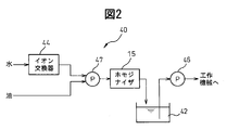
- FIG. 2 is a block diagram showing the first embodiment of the machining liquid supply apparatus.
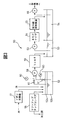
- FIG. 3 is a block diagram showing a second embodiment of the machining liquid supply apparatus.
- FIG. 4 is a cross-sectional view of a pressure type homogenizer.
- FIG. 1 shows a machine tool of the present embodiment.
- the machine tool of the present invention is not limited to the vertical machining center shown in FIG. 1, and a horizontal machining center, a turning center, and other machine tools are also included in the machine tool of the present invention. As shown in FIG. 1,
- the machine tool 1 includes a table 4 fixed on a base 3, a slide base (not shown) that slides along a linear motion guide on the base 3, and a slide base A column (not shown) that slides along the linear motion guide, a spindle head 5 that is supported by the column so as to be movable in the vertical direction, and a spindle 6 that is rotatably supported by the spindle head 5.
- the table 4 relatively move in three axial directions orthogonal to each other.
- An end mill 8 is attached to the main shaft 6, and a work 2 is attached to the table 4.
- the machine tool 1 introduces a processing fluid mixed with water and oil that does not contain an emulsifier and is pressurized to a predetermined pressure from a processing fluid supply device 10 outside the device, and uniformly disperses the oil in water by making the oil fine particles.
- a homogenizer 15 is provided.
- the homogenized machining fluid is supplied to the machining area via a coolant nozzle 13 connected to the machining fluid supply pipe 12. Without using the coolant nozzle 13, the homogenized machining fluid may be introduced into the main shaft 6 from the rear portion of the main shaft 6 and supplied to the processing region from the tip of the end mill 8 through the main shaft 6 and the end mill 8. .
- the homogenizer 15 is not limited to the pressure type homogenizer as shown in FIG.
- aqueous working fluid used for processing are not limited except that it does not contain an emulsifier.
- oil fatty acids such as oleic acid and stearic acid, animal and vegetable oils, mineral oils, synthetic oils, and mixed oils thereof can be used.
- water tap water or deionized water not containing hydroxide ions can be used.
- the mixing ratio of oil to water is, for example, 5% to 50% by weight, and preferably 10% to 30% by weight.
- fine powders of solid lubricants such as silica, boron nitride and diamond can also be included.
- the particle size of the fine powder is nanometer to micrometer order.
- deionized water ion-exchanged water, distilled water or pure water can be used.
- the pressure type homogenizer 15 includes a housing 19 having a processing chamber 20 therein, and a valve seat attached to the front end surface 21 a of the housing 19 with the valve seat surface 25 a facing the processing chamber 20. 25.
- the valve seat 25 has a machining fluid inlet 26 that is introduced into the homogenizer 15 at a high pressure.
- a narrow gap 35 is formed between the valve seat surface 25a and the valve front end surface 31a.
- the valve front end surface 31a has a circular shape with a diameter of 30 mm, for example.
- On the inner wall surface of the housing on the outer periphery of the gap 35 there is provided an impact ring 34 on which the mixed liquid of water and oil that has passed through the gap 35 collides at high speed.
- the impact ring 34 is a consumable part that is replaced when the high-pressure liquid mixture collides and wears, and is made of a wear-resistant material such as ceramics or cemented carbide.
- the housing 19 and the impact ring 34 are formed separately.
- the mixed liquid of water and oil is accelerated through the gap 35, and fine particles on the order of micrometer of oil are converted into water by the impact force when colliding with the impact ring 34 and cavitation caused by decompression in the processing chamber 20.
- a working fluid that is uniformly dispersed is produced.
- the housing 19 has a front end opening 22a and a rear end opening 22b communicating with the processing chamber 20, and a discharge port 22c for discharging the homogenized processing liquid.
- a valve seat 25 is attached to the front end surface 21a, and the mixed liquid is introduced into the processing chamber 20 from an introduction port 26 communicating with the front end opening 22a.
- a valve 31 is fitted into the rear end opening 22b, and a valve front end surface 31a faces the valve seat surface 25a with a predetermined gap 35 therebetween.
- the valve 31 is fitted so that no gap is generated between the valve 31 and the rear end opening 22b.
- the size of the gap 35 between the valve tip surface 31a and the valve seat surface 25a can be adjusted, and the gap 35 is set according to the oil particle diameter and viscosity of the introduced mixed liquid and the pressure of the working liquid. For example, in the case of oil with a large particle diameter and high viscosity, the gap 35 is set wide, and in the case of oil with a small particle diameter and low viscosity, the gap 35 is set narrow.
- the interval 35 between the valve tip surface 31a and the valve seat surface 25a is set to about 0.1 mm. .
- the gap 35 between the valve front end surface 31a and the valve seat surface 25a is narrow, the generation capacity of the homogenized machining fluid is reduced, and a sufficient amount of machining fluid cannot be supplied to the machining area. In such a case, it becomes possible to supply a sufficient amount of machining fluid by providing the machine tool 1 with a tank for storing the homogenized machining fluid.
- the homogenized machining liquid is discharged from the discharge port 22 c and supplied to the machining area via the machining liquid supply pipe 12.
- the valve seat 25 is made of the same material as the housing 19.
- the inlet 26 into which the mixed liquid pressurized to a predetermined pressure is introduced is formed so that the processing liquid outlet side is narrower than the inlet side.
- the liquid mixture is increased in velocity by flowing through the gap 35 from the inlet 26 and collides with the impact ring 34.
- the valve 31 is formed of the same material as that of the housing 19 like the valve seat 25.
- the valve 31 has a base 33 fixed to the rear end surface 21 b of the housing 19 and a protrusion 32 that is fitted into the rear end opening 22 b of the housing 19 and protrudes into the processing chamber 20.
- the front end surface of the protrusion 32 is formed as a valve surface 31a, and forms a gap 35 between the valve surface 31a and the opposing valve seat surface 25a.
- the machine tool 1 includes the homogenizer 15 that generates a machining liquid in which oil is uniformly dispersed in water. Therefore, water and oil that are not compatible without using an emulsifier. The particles can be kept in a state that is difficult to separate for a long time.
- the tool life can be significantly extended in machining of metals such as titanium alloy, nickel alloy, and aluminum alloy, whose tool life is shortened by chipping and wear.
- metals such as titanium alloy, nickel alloy, and aluminum alloy
- a tool life of about 4 times can be achieved compared to machining a titanium alloy with a carbide end mill.
- the homogenizer 15 is provided in the middle of the machining liquid supply conduit 12 from the machining liquid supply device 10 to the machining area, the machining liquid is water in the tank of the machining liquid supply device 10 over time.
- the homogenizer 15 can regenerate the processing liquid in which oil is uniformly dispersed in water, and stable processing can be performed.
- heat-treated oil having a high boiling point as defined in Japanese Industrial Standards JIS K2242, for example, oil particles dispersed in the working fluid are transformed into high-temperature workpieces, tools, and machining wastes. Even if it touches, it becomes difficult to vaporize and the performance deterioration as a processing liquid can be suppressed.
- oil with a low vaporization temperature (low boiling point) chipping of the tool is likely to occur due to impact when the oil particles vaporize, but the occurrence of chipping is also suppressed by using heat-treated oil with a high boiling point.
- the machining liquid supply apparatus 40 includes a homogenizer 15 and a tank 42 that stores the homogenized machining liquid.
- the homogenizer 15 the pressure type homogenizer shown in FIG. 4 described above can be used. Deionized water and oil ion-exchanged by the ion exchanger 44 are introduced into the homogenizer 15 of the present embodiment.
- FIG. 3 shows a second embodiment of the machining fluid supply apparatus of the present invention.
- the machining fluid supply device 50 of the present embodiment includes a primary tank 52 that collects the machining fluid used for machining, and is suitable for a machine tool that is automatically operated for a long time.
- the machining fluid is carried from the machine tool together with the machining waste, and is separated into machining waste and machining fluid by the lift-up chip conveyor 56.
- the separated working fluid is stored in the primary tank 52 together with deionized water for replenishment ion-exchanged by the ion exchanger 57 and new oil to be replenished.
- deionized water commercially available ones or those already produced by other methods can be used.
- the liquid is pumped up by the pump 58 and supplied to the filter 59.
- a rotary cyclone filter can be used as the filter 59, and fine machining debris is removed by the filter 59 and the machining fluid is stirred to some extent.
- the upper layer 52a is a layer mainly containing a large amount of oil
- the lower layer 52b is a layer mainly containing much water.
- the suction pipe for sucking the liquid from the upper layer 52a is formed so as to move up and down together with the float, and is configured so that the liquid can always be sucked from near the liquid surface.
- the mixed liquid of water and oil is temporarily stored in the secondary tank 53 via the filter 59.
- the pressurized working fluid pumped up from the secondary tank 53 by the pump 63 is introduced into the homogenizer 64 to produce a working fluid in which oil is uniformly dispersed in water.
- the generated processing liquid is sterilized by the ultraviolet irradiation device 65 and then stored in the tertiary tank 54.
- the ultraviolet irradiation device 65 is effective for preventing corrosion of the machining fluid.
- the machining liquid pumped from the tertiary tank 54 by the pump 66 is supplied to the machining area.
- the machining liquid supply device 50 of the present embodiment is a form suitable for a machine tool that is arranged on a production line and is operated for a long time. By using this machining supply device 50, water and oil of the machining liquid are not separated. In addition, continuous and stable processing can be performed. As described above, an aqueous working liquid in which oil is uniformly dispersed in water without using an emulsifier can be generated by a homogenizer. By using this machining fluid, the wear resistance and chipping resistance of tools in machining of all metals including titanium alloy, nickel alloy, aluminum alloy and the like can be increased, and the tool life can be extended. Thereby, productivity of metal processing increases and processing costs including tool costs can be reduced. In addition, this invention is not limited to the said embodiment, In the range which does not deviate from the main point of this invention, it can deform
Landscapes
- Physics & Mathematics (AREA)
- Fluid Mechanics (AREA)
- Engineering & Computer Science (AREA)
- Mechanical Engineering (AREA)
- Auxiliary Devices For Machine Tools (AREA)
- Lubricants (AREA)
Abstract
工具(18)とワーク(2)とを相対移動させてワーク(2)を加工する工作機械(1)において、水と油を取り込んで、水に油を均一に分散させるホモジナイザ(15)を具備し、ホモジナイザ(15)で生成した加工液を加工領域に供給してワークを加工する。
Description
本発明は、加工液を供給しながらワークを切削、研削、ホーニング等機械加工する工作機械及び加工液供給装置、並びに加工液に関する。
ワークを機械加工する際に供給される加工液には、次のような作用がある。ワークと工具との間や工具と加工切屑との間に浸透して境界面の摩擦を減少させる潤滑作用と、構成刃先の生成や加工切屑の工具への溶着を防止する反溶着作用と、ワークと工具との間や工具と加工切屑との間で発生する摩擦熱や金属のせん断熱を吸収したり、ワークや工具を冷却したりする冷却作用である。加工液のこれらの作用は、加工液の種類によって変化する。油のみを使用する油性加工液は、潤滑作用や反溶着作用が強く、工具すくい面のクレータ摩耗や工具逃げ面のフランク摩耗の減少に効果的である。油を水に希釈して使用する水溶性加工液は、冷却作用が強く、工具摩耗の低減や仕上げ面品位の向上に効果的である。一般に、油性加工液は、加工温度が高くなる加工条件では発火の危険性があるため使用できず、発火の危険性がない低速での加工や、加工温度が高くならないワークの加工に使用される。水溶性加工液は、油性加工液に比べて潤滑作用及び反溶着作用が劣るものの、発火の危険性がないため、汎用的に使用されている。このため、高速での加工や、加工温度が高くなる難削材の加工には、水溶性加工液が用いられる。
切削加工に使用される加工液の従来の例が特許文献1に開示されている。特許文献1に記載された発明は、水溶性金属加工油剤を開示する。特許文献1には、水溶性金属加工油剤が、基油、窒化硼素微粉末及び乳化剤を含み、窒化硼素微粉末が、平均粒径が0.5μm以下の一次粒子を含むことが記載されている。また、乳化剤として、陰イオン性界面活性剤や、非イオン性界面活性剤や、これらの混合物を用いることが記載されている。
ホモジナイザは、液中に粒子を細かく粉砕して均一に分散させる装置である。このホモジナイザには、粒子を含む加圧された混合液を高速でインパクトリングに衝突させることにより、粒子を微細に粉砕して液中に分散させる圧力型と、ロータとステータとの微小間隙に粒子を含む混合液を供給した状態でロータを高速回転させることにより、粒子を微細にして液中に分散させるロータ・ステータ型とがある。圧力型のホモジナイザの従来の例が特許文献2に開示されている。特許文献2には、耐エロージョン性に優れたバルブ部品を使用して、硬質セラミックス粉末を液中に分散処理する圧力型のホモジナイザが記載されている。
加工液は、一般に、予め機外で生成され、この加工液は工作機械に付属するタンクに貯蔵して使用される。タンク内の加工液が減少した場合は、作業者が加工液を補給する。長時間にわたり自動運転する工作機械の中には、加工液補給装置により自動で加工液を補給するものがある。工作機械の付属装置である加工液補給装置の従来の例が特許文献3に開示されている。この特許文献3には、混合機のジェットポンプ内でタンクから供給される原液と機外から供給される加圧水とを混合して加工液を生成することが開示されている。また、原液は、ジェットポンプの内筒内に設けた旋回羽根を旋回させることにより旋回流となり、均一に分散されるとの記載がある。
切削加工に使用される加工液の従来の例が特許文献1に開示されている。特許文献1に記載された発明は、水溶性金属加工油剤を開示する。特許文献1には、水溶性金属加工油剤が、基油、窒化硼素微粉末及び乳化剤を含み、窒化硼素微粉末が、平均粒径が0.5μm以下の一次粒子を含むことが記載されている。また、乳化剤として、陰イオン性界面活性剤や、非イオン性界面活性剤や、これらの混合物を用いることが記載されている。
ホモジナイザは、液中に粒子を細かく粉砕して均一に分散させる装置である。このホモジナイザには、粒子を含む加圧された混合液を高速でインパクトリングに衝突させることにより、粒子を微細に粉砕して液中に分散させる圧力型と、ロータとステータとの微小間隙に粒子を含む混合液を供給した状態でロータを高速回転させることにより、粒子を微細にして液中に分散させるロータ・ステータ型とがある。圧力型のホモジナイザの従来の例が特許文献2に開示されている。特許文献2には、耐エロージョン性に優れたバルブ部品を使用して、硬質セラミックス粉末を液中に分散処理する圧力型のホモジナイザが記載されている。
加工液は、一般に、予め機外で生成され、この加工液は工作機械に付属するタンクに貯蔵して使用される。タンク内の加工液が減少した場合は、作業者が加工液を補給する。長時間にわたり自動運転する工作機械の中には、加工液補給装置により自動で加工液を補給するものがある。工作機械の付属装置である加工液補給装置の従来の例が特許文献3に開示されている。この特許文献3には、混合機のジェットポンプ内でタンクから供給される原液と機外から供給される加圧水とを混合して加工液を生成することが開示されている。また、原液は、ジェットポンプの内筒内に設けた旋回羽根を旋回させることにより旋回流となり、均一に分散されるとの記載がある。
加工温度が高くなりやすいニッケル合金などの耐熱鋼やステンレス鋼、また、工具の刃先に溶着を生じやすいアルミニウム合金やチタン合金は、工具の寿命を短くするワークのグループに属する。アルミニウム合金やチタン合金の加工では、加工屑が工具の切れ刃に溶着し、チッピングを誘発することにより工具寿命が短くなる。これらの金属の加工では、加工温度を低下させると共に、溶着を抑制して工具寿命を延長させるために、水と油を所定の比率で混合した水溶性加工液が用いられる。水溶性加工液には、相溶性を有しない水と油を用い、水に油粒子を分散させて均一化するために、乳化剤が添加される。乳化剤を含んだ水溶性加工液は、一般に、エマルジョンタイプの水溶性加工液と呼ばれる。乳化剤は、特許文献1に記載されているように、陰イオン性界面活性剤や、非イオン性界面活性剤や、これらの混合物である。乳化剤は、表面張力を抑制する効果があるため、水に油を分散させて均一な加工液を作ることができる利点がある一方、チタン合金やニッケル合金やアルミニウム合金などの金属の加工に使用すると、工具寿命が短くなるという問題があった。また、加工液の水には水酸化物イオンを含む水道水が使用されていたため、水酸化物イオンがワークの加工直後の金属表面に結合して、油の粒子が金属表面に付着しにくくなるという問題があった。
本発明は、上記の問題点を解決するためになされたものであり、水性加工液を使用してチタン合金やニッケル合金やアルミニウム合金など、金属を加工した際に工具寿命を延ばすことができる工作機械及び加工液供給装置、並びに加工液を提供することを目的とする。
上記目的を達成するために、本発明によれば、工具とワークとを相対移動させてワークを加工する工作機械において、水と油を取り込んで、水に油を分散させるホモジナイザを具備し、ホモジナイザで生成した加工液を加工領域に供給してワークを加工する工作機械が提供される。ホモジナイザは、加工液供給装置から加工領域へ向かう加工液供給管路の途中に設けられることが好ましい。
この構成による工作機械は、乳化剤を含まなくても水に油を均一に分散させ、かつ、水と油が分離しにくい加工液を自身で加工の前に生成し、その加工液を加工領域に供給して加工する。
また、本発明によれば、工作機械に加工液を供給する加工液供給装置において、水と油を取り込んで、水に油を分散させるホモジナイザを具備する加工液供給装置が提供される。水には脱イオン水を用いることが好ましい。脱イオン水を生成するためのイオン交換器を更に具備してもよい。ホモジナイザで生成した加工液を貯留する加工液タンクと、加工液タンクに貯留している加工液を吐出するポンプと、を更に具備することもできる。工作機械から回収され貯留された加工液又は貯留された水と油の混合液の上部の層と下部の層からそれぞれ液を汲み上げ、上部の層の液と下部の層の液とを混合状態でホモジナイザに導入するポンプを更に具備するようにしてもよい。ホモジナイザを、水と油の加圧された混合液を導入する間隙と、間隙を通過して増速された混合液を壁面に衝突させるとともに減圧し、水に油を分散させる処理室と、を有した圧力型のホモジナイザとすることもできる。
この構成による加工液供給装置は、乳化剤を含まなくても水に油を均一に分散させ、かつ、水と油が分離しにくい加工液を生成し、その加工液を工作機械に供給する。
また、本発明によれば、工作機械の加工領域に供給する加工液であって、所定の割合で水と油をホモジナイザに導入し、乳化剤を用いずに水に油を分散させて生成される加工液が提供される。この場合、熱処理油のように沸点の高い油を用いることが好ましい。
以上の如く、本発明の工作機械によれば、ホモジナイザにより、乳化剤を用いずに相溶性を有しない水と油粒子とが均一に分散した水性加工液を生成することができる。生成された加工液は、水と油とが分離しづらくなっているため、長期間にわたり加工液による所望の作用及び効果を得ることができる。この加工液を加工領域に供給することにより、チッピングや摩耗により工具寿命が短くなる金属、例えばチタン合金やニッケル合金やアルミニウム合金等の金属や他のあらゆる金属の加工において、工具寿命を格段に延長することができる。このため、生産性が向上し、工具費を含めた加工コストを低減することができる。ホモジナイザの構造は特に限定されず、圧力型やロータ・ステータ型のホモジナイザを用いることができる。
また、ホモジナイザが加工液供給装置から加工領域へ向かう加工液供給管路の途中に設けられているので、加工液供給装置のタンク内に貯留された加工液が時間の経過により水と油に分離した場合であっても、ホモジナイザにより水に油が均一に分散した加工液を生成することができる。
本発明の加工液供給装置によれば、乳化剤を用いずに、水に油が均一に分散し、水と油とが分離しにくい水性加工液を生成することができる。この加工液を使用することによって、例えばチタン合金やニッケル合金やアルミニウム合金等の金属や他のあらゆる金属の加工において、工具の寿命を延長することができる。また、脱イオン水を用いて、水酸化物イオンを含まない加工液を生成することができるため、ワークの金属表面に油の粒子が付着しやすくなり、工具に加工屑が溶着しにくくなる。タンクに貯留された加工液又は水と油の混合液の上部の層と下部の層から別々に液を汲み上げてホモジナイザに導入するため、水と油の混合比率が所定の割合の加工液を生成することができる。圧力型のホモジナイザを用いた場合には、比較的簡単な構成で水と油の混合液をインパクトリングに衝突させるとともにキャビテーションを発生させて、水に油を均一に分散させた加工液を生成することができる。ホモジナイジングされた加工液がタンクに貯留されることにより、加工に必要な十分な量の加工液を供給することができ、工作機械を長時間運転することができる。
本発明の加工液によれば、生成した加工液には、工具寿命を短くする乳化剤が使用されていないため、チタン合金やニッケル合金やアルミニウム合金を始めあらゆる金属加工において、工具寿命を延長することができる。また、水性加工液のため、火災の危険性がない。この場合、熱処理油のように沸点の高い油を用いると、加工液中の微細化された油が高温のワークや工具や加工屑に触れても気化しにくくなるので、加工液の性能劣化を抑制できる。加工液中の油が気化する衝撃により工具がチッピングを起こすおそれも低下する。
本発明は、上記の問題点を解決するためになされたものであり、水性加工液を使用してチタン合金やニッケル合金やアルミニウム合金など、金属を加工した際に工具寿命を延ばすことができる工作機械及び加工液供給装置、並びに加工液を提供することを目的とする。
上記目的を達成するために、本発明によれば、工具とワークとを相対移動させてワークを加工する工作機械において、水と油を取り込んで、水に油を分散させるホモジナイザを具備し、ホモジナイザで生成した加工液を加工領域に供給してワークを加工する工作機械が提供される。ホモジナイザは、加工液供給装置から加工領域へ向かう加工液供給管路の途中に設けられることが好ましい。
この構成による工作機械は、乳化剤を含まなくても水に油を均一に分散させ、かつ、水と油が分離しにくい加工液を自身で加工の前に生成し、その加工液を加工領域に供給して加工する。
また、本発明によれば、工作機械に加工液を供給する加工液供給装置において、水と油を取り込んで、水に油を分散させるホモジナイザを具備する加工液供給装置が提供される。水には脱イオン水を用いることが好ましい。脱イオン水を生成するためのイオン交換器を更に具備してもよい。ホモジナイザで生成した加工液を貯留する加工液タンクと、加工液タンクに貯留している加工液を吐出するポンプと、を更に具備することもできる。工作機械から回収され貯留された加工液又は貯留された水と油の混合液の上部の層と下部の層からそれぞれ液を汲み上げ、上部の層の液と下部の層の液とを混合状態でホモジナイザに導入するポンプを更に具備するようにしてもよい。ホモジナイザを、水と油の加圧された混合液を導入する間隙と、間隙を通過して増速された混合液を壁面に衝突させるとともに減圧し、水に油を分散させる処理室と、を有した圧力型のホモジナイザとすることもできる。
この構成による加工液供給装置は、乳化剤を含まなくても水に油を均一に分散させ、かつ、水と油が分離しにくい加工液を生成し、その加工液を工作機械に供給する。
また、本発明によれば、工作機械の加工領域に供給する加工液であって、所定の割合で水と油をホモジナイザに導入し、乳化剤を用いずに水に油を分散させて生成される加工液が提供される。この場合、熱処理油のように沸点の高い油を用いることが好ましい。
以上の如く、本発明の工作機械によれば、ホモジナイザにより、乳化剤を用いずに相溶性を有しない水と油粒子とが均一に分散した水性加工液を生成することができる。生成された加工液は、水と油とが分離しづらくなっているため、長期間にわたり加工液による所望の作用及び効果を得ることができる。この加工液を加工領域に供給することにより、チッピングや摩耗により工具寿命が短くなる金属、例えばチタン合金やニッケル合金やアルミニウム合金等の金属や他のあらゆる金属の加工において、工具寿命を格段に延長することができる。このため、生産性が向上し、工具費を含めた加工コストを低減することができる。ホモジナイザの構造は特に限定されず、圧力型やロータ・ステータ型のホモジナイザを用いることができる。
また、ホモジナイザが加工液供給装置から加工領域へ向かう加工液供給管路の途中に設けられているので、加工液供給装置のタンク内に貯留された加工液が時間の経過により水と油に分離した場合であっても、ホモジナイザにより水に油が均一に分散した加工液を生成することができる。
本発明の加工液供給装置によれば、乳化剤を用いずに、水に油が均一に分散し、水と油とが分離しにくい水性加工液を生成することができる。この加工液を使用することによって、例えばチタン合金やニッケル合金やアルミニウム合金等の金属や他のあらゆる金属の加工において、工具の寿命を延長することができる。また、脱イオン水を用いて、水酸化物イオンを含まない加工液を生成することができるため、ワークの金属表面に油の粒子が付着しやすくなり、工具に加工屑が溶着しにくくなる。タンクに貯留された加工液又は水と油の混合液の上部の層と下部の層から別々に液を汲み上げてホモジナイザに導入するため、水と油の混合比率が所定の割合の加工液を生成することができる。圧力型のホモジナイザを用いた場合には、比較的簡単な構成で水と油の混合液をインパクトリングに衝突させるとともにキャビテーションを発生させて、水に油を均一に分散させた加工液を生成することができる。ホモジナイジングされた加工液がタンクに貯留されることにより、加工に必要な十分な量の加工液を供給することができ、工作機械を長時間運転することができる。
本発明の加工液によれば、生成した加工液には、工具寿命を短くする乳化剤が使用されていないため、チタン合金やニッケル合金やアルミニウム合金を始めあらゆる金属加工において、工具寿命を延長することができる。また、水性加工液のため、火災の危険性がない。この場合、熱処理油のように沸点の高い油を用いると、加工液中の微細化された油が高温のワークや工具や加工屑に触れても気化しにくくなるので、加工液の性能劣化を抑制できる。加工液中の油が気化する衝撃により工具がチッピングを起こすおそれも低下する。
図1は、本発明の工作機械の一実施形態を示す図である。
図2は、加工液供給装置の第1の実施形態を示すブロック図である。
図3は、加工液供給装置の第2の実施形態を示すブロック図である。
図4は、圧力型ホモジナイザの断面図である。
図2は、加工液供給装置の第1の実施形態を示すブロック図である。
図3は、加工液供給装置の第2の実施形態を示すブロック図である。
図4は、圧力型ホモジナイザの断面図である。
以下において、本発明の工作機械の一実施形態について詳細に説明する。図1には、本実施形態の工作機械が示されている。本発明の工作機械は、図1に示される立形マシニングセンタに限定されるものではなく、横形マシニングセンタや、ターニングセンタや、他の工作機械も本発明の工作機械に含まれる。
図1に示すように、本実施形態の工作機械1は、ベース3上に固定されるテーブル4と、ベース3上の直動ガイドに沿ってスライドするスライド台(図示しない)と、スライド台上の直動ガイドに沿ってスライドするコラム(図示しない)と、コラムに上下方向に移動可能に支持された主軸頭5と、主軸頭5に回転自在に保持された主軸6とを備え、主軸6とテーブル4とは互いに直交する3軸方向に相対移動する。主軸6には、エンドミル8が装着され、テーブル4にはワーク2が取り付けられている。さらに、工作機械1は、機外の加工液供給装置10から所定の圧力に加圧された乳化剤を含まない水と油の混合した加工液を導入し、油を微粒子にして水に均一に分散させるホモジナイザ15を備えている。ホモジナイジングされた加工液は、加工液供給管路12に接続するクーラントノズル13を介して加工領域に供給される。クーラントノズル13を用いずに、ホモジナイジングされた加工液を主軸6の後部から主軸6の内部に導入し、主軸6及びエンドミル8の内部を通してエンドミル8の先端から加工領域に供給してもよい。ホモジナイザ15は、図4に示されているような圧力型のホモジナイザに制限されるものではなく、ロータとステータとの微小間隙に水と油を導入し、ロータを高速で回転させて水に油を均一に分散させるロータ・ステータ型のホモジナイザを用いることも可能である。
加工に使用される水性加工液の種類や成分は、乳化剤を含まないことを除き、制限されるものではない。油には、オレイン酸、ステアリン酸等の脂肪酸、動植物油、鉱油、合成油、これらの混合油を使用することができる。水には、水道水や、水酸化物イオンを含まない脱イオン水を使用することができる。油分の水に対する混合割合は、例えば5重量%~50重量%であり、とくに10重量%~30重量%とすることが好ましくい。水性加工液の潤滑作用を高めるために、シリカ、窒化硼素、ダイヤモンド等の固体潤滑剤の微粉末を含むこともできる。微粉末の粒径はナノメートルないしマイクロメートルオーダである。脱イオン水としては、イオン交換水、蒸留水又は純水を用いることができる。
図4に示すように、圧力型のホモジナイザ15は、内部に処理室20を有するハウジング19と、バルブシート面25aを処理室20に向けた状態でハウジング19の前側端面21aに装着されるバルブシート25とを備える。バルブシート25は、ホモジナイザ15の内部に高圧で導入される加工液の導入口26を有する。バルブシート面25aとバルブ先端面31aとの間には狭い間隙35が形成されている。バルブ先端面31aは、例えば直径30mmの円形状をなしている。間隙35の外周のハウジングの内壁面には、間隙35を通過した水と油の混合液が高速で衝突するインパクトリング34を備える。インパクトリング34は、高圧の混合液が衝突して摩耗した際に交換される消耗部品であり、セラミックスや超硬合金などの耐摩耗性を有する材料で構成されている。本実施形態では、インパクトリング34の交換を容易にするため、ハウジング19とインパクトリング34とが別体として形成されている。水と油の混合液は、間隙35を通過して増速され、インパクトリング34に衝突したときの衝撃力と処理室20で減圧されて起きるキャビテーションとによって、油のマイクロメートルオーダの微粒子が水に均一に分散された加工液が生成される。
ハウジング19は、処理室20に連通する前端開口22a及び後端開口22bと、ホモジナイジングされた加工液を排出する排出口22cとを有する。前側端面21aにはバルブシート25が装着され、前端開口22aに連通する導入口26から混合液が処理室20に導入される。後端開口22bには、バルブ31が嵌入され、バルブ先端面31aがバルブシート面25aに所定の間隙35を有して対向している。バルブ31は、後端開口22bとの間に隙間が生じないように嵌入されている。バルブ先端面31aとバルブシート面25aとの間隙35の大きさは調整可能であり、導入される混合液の油の粒子径や粘度、加工液の圧力に応じて間隙35が設定される。例えば、粒子径が大きく、高粘度の油の場合には、間隙35が広く設定され、粒子径が小さく、低粘度の油の場合には、間隙35が狭く設定される。オレイン酸と水を含む加工液が使用され、11MPaの圧力で、数μmの油粒子を作成する際には、バルブ先端面31aとバルブシート面25aの間隔35が約0.1mmに設定される。バルブ先端面31aとバルブシート面25aの間隙35が狭い場合には、ホモジナイジングされる加工液の生成能力が小さくなり、加工領域に十分な量の加工液を供給することができないが、このような場合には、工作機械1がホモジナイジングされた加工液を貯留するタンクを備えることで、十分な量の加工液を供給することが可能となる。水と油の混合液は、インパクトリング34に高速で衝突し、処理室20で減圧され、衝撃力とキャビテーションにより水に油粒子が均一に分散する。ホモジナイジングされた加工液は、排出口22cから排出され、加工液供給管路12を介して加工領域に供給される。
バルブシート25は、ハウジング19と同一材料で形成される。所定の圧力に加圧された混合液が導入される導入口26は、加工液の出口側が入口側よりも狭く形成されている。混合液は、導入口26から間隙35を流れることにより、増速されてインパクトリング34に衝突する。
バルブ31は、バルブシート25と同様にハウジング19と同一材料で形成される。バルブ31は、ハウジング19の後側端面21bに固定される基部33と、ハウジング19の後端開口22bに嵌入され、処理室20内に突出する突部32とを有している。突部32の先端面は、バルブ面31aとして形成され、対向するバルブシート面25aとの間に間隙35を形成する。
以上のように、本実施形態の工作機械1は、水に油が均一に分散した加工液を生成するホモジナイザ15を備えているので、乳化剤を使用することなく、相溶性を有しない水と油粒子とを長時間にわたって分離しにくい状態に保つことができる。この加工液を加工領域に供給することにより、チタン合金やニッケル合金やアルミニウム合金等、チッピングや摩耗により工具寿命が短くなる金属の加工において、工具寿命を格段に延長することができる。乳化剤を含む市販のエマルジョンタイプの水溶性加工液を使用して、超硬エンドミルでチタン合金を加工した場合に比べて、約4倍の工具寿命を達成することができる。本実施形態では、ホモジナイザ15が加工液供給装置10から加工領域へ向かう加工液供給管路12の途中に設けられているので、加工液供給装置10のタンク内で加工液が時間の経過により水と油に分離している場合であっても、ホモジナイザ15により水に油が均一に分散した加工液を再生することができ、安定した加工を行うことができる。
加工液中の油として、例えば日本工業規格JIS K2242に規定されているような沸点の高い熱処理油を用いることにより、加工液中に分散している油粒子が高温のワークや工具や加工屑に触れても気化しにくくなり、加工液としての性能劣化を抑制できる。また、気化温度の低い(沸点の低い)油を用いると、油粒子が気化するときの衝撃で工具のチッピングが発生しやすくなるが、沸点の高い熱処理油を用いることで、チッピングの発生も抑制できる。なお、加工液に固体潤滑剤の微粒子を含む場合でも、ホモジナイジングすることにより、固体潤滑剤の微粉末も水に均一に分散されて分離しにくくなる。
次に、図2を参照して、本発明の加工液供給装置の第1の実施形態について説明する。本実施形態の加工液供給装置40は、図1に示す加工液供給装置10とは異なり、ホモジナイザ15と、ホモジナイジングされた加工液を貯留するタンク42とを備える。ホモジナイザ15には、上述した図4に示す圧力型のホモジナイザを使用することができる。本実施形態のホモジナイザ15には、イオン交換器44によりイオン交換された脱イオン水と油とが導入される。水酸化物イオンを含む水道水に代えて、水酸化物イオンを含まない脱イオン水が使用されることで、加工直後のワークの金属表面に水酸化物イオンが結合することが防止され、油分がワーク表面に直接的に付着し、加工液の潤滑作用が高められる。これにより、工具に加工屑が溶着しにくくなり、チッピングの発生が抑制される。ホモジナイジングされた加工液はタンク42からポンプ46により汲み上げられ、加工領域に供給されるので、加工領域に十分な量の加工液を供給することができる。
図3は、本発明の加工液供給装置の第2の実施形態を示す。本実施形態の加工液供給装置50は、加工に使用された加工液を回収する一次タンク52を備えており、長時間にわたり自動運転される工作機械に適する形態である。加工液は、工作機械から加工屑とともに運ばれ、リフトアップチップコンベヤ56により加工屑と加工液とに分離される。分離された加工液は、イオン交換器57によりイオン交換された補給用の脱イオン水と、補給される新しい油と共に一次タンク52に貯留される。脱イオン水には、市販されているものや、他の方法で既に生成されたものを使用することができる。一次タンク52内の水と油の混合液の上部の層52aと下部の層52bからは、それぞれ液がポンプ58により汲み上げられ、フィルタ59に供給される。フィルタ59には、回転式のサイクロンフィルタを用いることができ、このフィルタ59で細かな加工屑が除去されるとともに、加工液がある程度攪拌される。上部の層52aは主として油分が多い層であり、下部の層52bは主として水分の多い層である。上下の層52a、52bからそれぞれ液がポンプ58により汲み上げられるとき、作業者は各流量計60を見ながら各絞り弁61を開閉することにより流量を調節して、水と油を所定の混合割合にする。なお、上部の層52aから液を吸入する吸入管は、フロートとともに上下動するように形成され、常に液面付近から液を吸入できるように構成されている。
水と油の混合液はフィルタ59を経由して二次タンク53に一旦貯留される。二次タンク53からポンプ63により汲み上げた加圧された加工液は、ホモジナイザ64に導入され、水に油が均一に分散された加工液が生成される。生成された加工液は、紫外線照射装置65により滅菌処理された後、三次タンク54に貯留される。紫外線照射装置65は加工液の腐食防止に有効である。加工領域には、三次タンク54からポンプ66により汲み上げられた加工液が供給される。本実施形態の加工液供給装置50は、生産ラインに配置され、長時間運転される工作機械に適する形態であり、この加工供給装置50を用いることにより、加工液の水と油を分離させずに、連続して安定した加工を行うことができる。
以上のように、ホモジナイザにより、乳化剤を用いずに水に油を均一に分散させた水性加工液を生成することができる。この加工液を使用することによって、チタン合金やニッケル合金やアルミニウム合金等を始めとして、あらゆる金属の加工における工具の耐摩耗性、耐チッピング性が高まり、工具寿命を延長することができる。これにより、金属加工の生産性が高まり、工具費を含めた加工コストを低減することができる。
なお、本発明は上記実施形態に限定されるものではなく、本発明の骨子を逸脱しない範囲で種々変形して実施することができる。
図1に示すように、本実施形態の工作機械1は、ベース3上に固定されるテーブル4と、ベース3上の直動ガイドに沿ってスライドするスライド台(図示しない)と、スライド台上の直動ガイドに沿ってスライドするコラム(図示しない)と、コラムに上下方向に移動可能に支持された主軸頭5と、主軸頭5に回転自在に保持された主軸6とを備え、主軸6とテーブル4とは互いに直交する3軸方向に相対移動する。主軸6には、エンドミル8が装着され、テーブル4にはワーク2が取り付けられている。さらに、工作機械1は、機外の加工液供給装置10から所定の圧力に加圧された乳化剤を含まない水と油の混合した加工液を導入し、油を微粒子にして水に均一に分散させるホモジナイザ15を備えている。ホモジナイジングされた加工液は、加工液供給管路12に接続するクーラントノズル13を介して加工領域に供給される。クーラントノズル13を用いずに、ホモジナイジングされた加工液を主軸6の後部から主軸6の内部に導入し、主軸6及びエンドミル8の内部を通してエンドミル8の先端から加工領域に供給してもよい。ホモジナイザ15は、図4に示されているような圧力型のホモジナイザに制限されるものではなく、ロータとステータとの微小間隙に水と油を導入し、ロータを高速で回転させて水に油を均一に分散させるロータ・ステータ型のホモジナイザを用いることも可能である。
加工に使用される水性加工液の種類や成分は、乳化剤を含まないことを除き、制限されるものではない。油には、オレイン酸、ステアリン酸等の脂肪酸、動植物油、鉱油、合成油、これらの混合油を使用することができる。水には、水道水や、水酸化物イオンを含まない脱イオン水を使用することができる。油分の水に対する混合割合は、例えば5重量%~50重量%であり、とくに10重量%~30重量%とすることが好ましくい。水性加工液の潤滑作用を高めるために、シリカ、窒化硼素、ダイヤモンド等の固体潤滑剤の微粉末を含むこともできる。微粉末の粒径はナノメートルないしマイクロメートルオーダである。脱イオン水としては、イオン交換水、蒸留水又は純水を用いることができる。
図4に示すように、圧力型のホモジナイザ15は、内部に処理室20を有するハウジング19と、バルブシート面25aを処理室20に向けた状態でハウジング19の前側端面21aに装着されるバルブシート25とを備える。バルブシート25は、ホモジナイザ15の内部に高圧で導入される加工液の導入口26を有する。バルブシート面25aとバルブ先端面31aとの間には狭い間隙35が形成されている。バルブ先端面31aは、例えば直径30mmの円形状をなしている。間隙35の外周のハウジングの内壁面には、間隙35を通過した水と油の混合液が高速で衝突するインパクトリング34を備える。インパクトリング34は、高圧の混合液が衝突して摩耗した際に交換される消耗部品であり、セラミックスや超硬合金などの耐摩耗性を有する材料で構成されている。本実施形態では、インパクトリング34の交換を容易にするため、ハウジング19とインパクトリング34とが別体として形成されている。水と油の混合液は、間隙35を通過して増速され、インパクトリング34に衝突したときの衝撃力と処理室20で減圧されて起きるキャビテーションとによって、油のマイクロメートルオーダの微粒子が水に均一に分散された加工液が生成される。
ハウジング19は、処理室20に連通する前端開口22a及び後端開口22bと、ホモジナイジングされた加工液を排出する排出口22cとを有する。前側端面21aにはバルブシート25が装着され、前端開口22aに連通する導入口26から混合液が処理室20に導入される。後端開口22bには、バルブ31が嵌入され、バルブ先端面31aがバルブシート面25aに所定の間隙35を有して対向している。バルブ31は、後端開口22bとの間に隙間が生じないように嵌入されている。バルブ先端面31aとバルブシート面25aとの間隙35の大きさは調整可能であり、導入される混合液の油の粒子径や粘度、加工液の圧力に応じて間隙35が設定される。例えば、粒子径が大きく、高粘度の油の場合には、間隙35が広く設定され、粒子径が小さく、低粘度の油の場合には、間隙35が狭く設定される。オレイン酸と水を含む加工液が使用され、11MPaの圧力で、数μmの油粒子を作成する際には、バルブ先端面31aとバルブシート面25aの間隔35が約0.1mmに設定される。バルブ先端面31aとバルブシート面25aの間隙35が狭い場合には、ホモジナイジングされる加工液の生成能力が小さくなり、加工領域に十分な量の加工液を供給することができないが、このような場合には、工作機械1がホモジナイジングされた加工液を貯留するタンクを備えることで、十分な量の加工液を供給することが可能となる。水と油の混合液は、インパクトリング34に高速で衝突し、処理室20で減圧され、衝撃力とキャビテーションにより水に油粒子が均一に分散する。ホモジナイジングされた加工液は、排出口22cから排出され、加工液供給管路12を介して加工領域に供給される。
バルブシート25は、ハウジング19と同一材料で形成される。所定の圧力に加圧された混合液が導入される導入口26は、加工液の出口側が入口側よりも狭く形成されている。混合液は、導入口26から間隙35を流れることにより、増速されてインパクトリング34に衝突する。
バルブ31は、バルブシート25と同様にハウジング19と同一材料で形成される。バルブ31は、ハウジング19の後側端面21bに固定される基部33と、ハウジング19の後端開口22bに嵌入され、処理室20内に突出する突部32とを有している。突部32の先端面は、バルブ面31aとして形成され、対向するバルブシート面25aとの間に間隙35を形成する。
以上のように、本実施形態の工作機械1は、水に油が均一に分散した加工液を生成するホモジナイザ15を備えているので、乳化剤を使用することなく、相溶性を有しない水と油粒子とを長時間にわたって分離しにくい状態に保つことができる。この加工液を加工領域に供給することにより、チタン合金やニッケル合金やアルミニウム合金等、チッピングや摩耗により工具寿命が短くなる金属の加工において、工具寿命を格段に延長することができる。乳化剤を含む市販のエマルジョンタイプの水溶性加工液を使用して、超硬エンドミルでチタン合金を加工した場合に比べて、約4倍の工具寿命を達成することができる。本実施形態では、ホモジナイザ15が加工液供給装置10から加工領域へ向かう加工液供給管路12の途中に設けられているので、加工液供給装置10のタンク内で加工液が時間の経過により水と油に分離している場合であっても、ホモジナイザ15により水に油が均一に分散した加工液を再生することができ、安定した加工を行うことができる。
加工液中の油として、例えば日本工業規格JIS K2242に規定されているような沸点の高い熱処理油を用いることにより、加工液中に分散している油粒子が高温のワークや工具や加工屑に触れても気化しにくくなり、加工液としての性能劣化を抑制できる。また、気化温度の低い(沸点の低い)油を用いると、油粒子が気化するときの衝撃で工具のチッピングが発生しやすくなるが、沸点の高い熱処理油を用いることで、チッピングの発生も抑制できる。なお、加工液に固体潤滑剤の微粒子を含む場合でも、ホモジナイジングすることにより、固体潤滑剤の微粉末も水に均一に分散されて分離しにくくなる。
次に、図2を参照して、本発明の加工液供給装置の第1の実施形態について説明する。本実施形態の加工液供給装置40は、図1に示す加工液供給装置10とは異なり、ホモジナイザ15と、ホモジナイジングされた加工液を貯留するタンク42とを備える。ホモジナイザ15には、上述した図4に示す圧力型のホモジナイザを使用することができる。本実施形態のホモジナイザ15には、イオン交換器44によりイオン交換された脱イオン水と油とが導入される。水酸化物イオンを含む水道水に代えて、水酸化物イオンを含まない脱イオン水が使用されることで、加工直後のワークの金属表面に水酸化物イオンが結合することが防止され、油分がワーク表面に直接的に付着し、加工液の潤滑作用が高められる。これにより、工具に加工屑が溶着しにくくなり、チッピングの発生が抑制される。ホモジナイジングされた加工液はタンク42からポンプ46により汲み上げられ、加工領域に供給されるので、加工領域に十分な量の加工液を供給することができる。
図3は、本発明の加工液供給装置の第2の実施形態を示す。本実施形態の加工液供給装置50は、加工に使用された加工液を回収する一次タンク52を備えており、長時間にわたり自動運転される工作機械に適する形態である。加工液は、工作機械から加工屑とともに運ばれ、リフトアップチップコンベヤ56により加工屑と加工液とに分離される。分離された加工液は、イオン交換器57によりイオン交換された補給用の脱イオン水と、補給される新しい油と共に一次タンク52に貯留される。脱イオン水には、市販されているものや、他の方法で既に生成されたものを使用することができる。一次タンク52内の水と油の混合液の上部の層52aと下部の層52bからは、それぞれ液がポンプ58により汲み上げられ、フィルタ59に供給される。フィルタ59には、回転式のサイクロンフィルタを用いることができ、このフィルタ59で細かな加工屑が除去されるとともに、加工液がある程度攪拌される。上部の層52aは主として油分が多い層であり、下部の層52bは主として水分の多い層である。上下の層52a、52bからそれぞれ液がポンプ58により汲み上げられるとき、作業者は各流量計60を見ながら各絞り弁61を開閉することにより流量を調節して、水と油を所定の混合割合にする。なお、上部の層52aから液を吸入する吸入管は、フロートとともに上下動するように形成され、常に液面付近から液を吸入できるように構成されている。
水と油の混合液はフィルタ59を経由して二次タンク53に一旦貯留される。二次タンク53からポンプ63により汲み上げた加圧された加工液は、ホモジナイザ64に導入され、水に油が均一に分散された加工液が生成される。生成された加工液は、紫外線照射装置65により滅菌処理された後、三次タンク54に貯留される。紫外線照射装置65は加工液の腐食防止に有効である。加工領域には、三次タンク54からポンプ66により汲み上げられた加工液が供給される。本実施形態の加工液供給装置50は、生産ラインに配置され、長時間運転される工作機械に適する形態であり、この加工供給装置50を用いることにより、加工液の水と油を分離させずに、連続して安定した加工を行うことができる。
以上のように、ホモジナイザにより、乳化剤を用いずに水に油を均一に分散させた水性加工液を生成することができる。この加工液を使用することによって、チタン合金やニッケル合金やアルミニウム合金等を始めとして、あらゆる金属の加工における工具の耐摩耗性、耐チッピング性が高まり、工具寿命を延長することができる。これにより、金属加工の生産性が高まり、工具費を含めた加工コストを低減することができる。
なお、本発明は上記実施形態に限定されるものではなく、本発明の骨子を逸脱しない範囲で種々変形して実施することができる。
1 工作機械
10,40,50 加工液供給装置
15 ホモジナイザ
19 ハウジング
25 バルブシート
31 バルブ
34 インパクトリング
35 間隙
10,40,50 加工液供給装置
15 ホモジナイザ
19 ハウジング
25 バルブシート
31 バルブ
34 インパクトリング
35 間隙
Claims (10)
- 工具とワークとを相対移動させてワークを加工する工作機械において、
水と油を取り込んで、前記水に前記油を分散させるホモジナイザを具備し、前記ホモジナイザで生成した加工液を加工領域に供給してワークを加工することを特徴とした工作機械。 - 前記ホモジナイザは、加工液供給装置から加工領域へ向かう加工液供給管路の途中に設けられている請求項1に記載の工作機械。
- 工作機械に加工液を供給する加工液供給装置において、
水と油を取り込んで、前記水に前記油を分散させるホモジナイザを具備することを特徴とした加工液供給装置。 - 前記水に脱イオン水を用いる請求項3に記載の加工液供給装置。
- イオン交換器を更に具備し、前記水に前記イオン交換器で生成した脱イオン水を用いる請求項3に記載の加工液供給装置。
- 前記ホモジナイザで生成した加工液を貯留する加工液タンクと、前記加工液タンクに貯留している加工液を吐出するポンプと、を更に具備する請求項3に記載の加工液供給装置。
- 工作機械から回収され貯留された加工液又は貯留された水と油の混合液の上部の層と下部の層からそれぞれ液を汲み上げ、前記上部の層の液と前記下部の層の液とを混合状態で前記ホモジナイザに導入するポンプを更に具備する請求項3に記載の加工液供給装置。
- 前記ホモジナイザは、前記水と前記油の加圧された混合液を導入する間隙と、前記間隙を通過して増速された混合液を壁面に衝突させるとともに減圧し、前記水に前記油を分散させる処理室と、を有した圧力型のホモジナイザである請求項3に記載の加工液供給装置。
- 工作機械の加工領域に供給する加工液であって、
所定の割合で水と油をホモジナイザに導入し、乳化剤を用いずに前記水に前記油を分散させて生成されることを特徴とした加工液。 - 前記油は、熱処理油である請求項9に記載の加工液。
Priority Applications (2)
| Application Number | Priority Date | Filing Date | Title |
|---|---|---|---|
| US13/579,615 US9022175B2 (en) | 2010-02-24 | 2011-01-31 | Machine tool, working fluid supply apparatus, and working fluid |
| EP11747163.1A EP2540441B1 (en) | 2010-02-24 | 2011-01-31 | Working fluid supply apparatus |
Applications Claiming Priority (2)
| Application Number | Priority Date | Filing Date | Title |
|---|---|---|---|
| JP2010038316A JP2011173199A (ja) | 2010-02-24 | 2010-02-24 | 工作機械及び加工液供給装置、並びに加工液 |
| JP2010-038316 | 2010-02-24 |
Publications (1)
| Publication Number | Publication Date |
|---|---|
| WO2011105199A1 true WO2011105199A1 (ja) | 2011-09-01 |
Family
ID=44506616
Family Applications (1)
| Application Number | Title | Priority Date | Filing Date |
|---|---|---|---|
| PCT/JP2011/052450 Ceased WO2011105199A1 (ja) | 2010-02-24 | 2011-01-31 | 工作機械及び加工液供給装置、並びに加工液 |
Country Status (4)
| Country | Link |
|---|---|
| US (1) | US9022175B2 (ja) |
| EP (1) | EP2540441B1 (ja) |
| JP (1) | JP2011173199A (ja) |
| WO (1) | WO2011105199A1 (ja) |
Families Citing this family (5)
| Publication number | Priority date | Publication date | Assignee | Title |
|---|---|---|---|---|
| US10120366B2 (en) * | 2014-09-08 | 2018-11-06 | Haas Automation, Inc. | Automatic machine tool coolant mixer |
| JP6302125B1 (ja) * | 2017-09-22 | 2018-03-28 | 株式会社松浦機械製作所 | 切削油の供給方法 |
| US10685863B2 (en) | 2018-04-27 | 2020-06-16 | Semiconductor Components Industries, Llc | Wafer thinning systems and related methods |
| JP6612401B1 (ja) * | 2018-07-26 | 2019-11-27 | 産機テクノス株式会社 | フィルタ式スラッジ回収装置 |
| JP7637413B2 (ja) * | 2021-11-29 | 2025-02-28 | 中部クリーン株式会社 | 水溶性切削油、水溶性切削油管理装置、および水溶性切削油管理方法 |
Citations (9)
| Publication number | Priority date | Publication date | Assignee | Title |
|---|---|---|---|---|
| JPH0478932U (ja) | 1990-11-16 | 1992-07-09 | ||
| JPH07115276B2 (ja) | 1990-09-25 | 1995-12-13 | 広和機械設計工業株式会社 | 切削液の補給装置 |
| JP2000045018A (ja) * | 1998-07-28 | 2000-02-15 | Idemitsu Kosan Co Ltd | 熱処理油組成物 |
| JP2003094283A (ja) * | 2002-08-06 | 2003-04-03 | Taiyu Kk | 切削加工方法及び切削油 |
| JP2004182879A (ja) * | 2002-12-04 | 2004-07-02 | Osamu Yamamoto | 高性能水溶性金属加工油剤 |
| JP3753728B2 (ja) | 2005-01-06 | 2006-03-08 | 修 山本 | 高性能水溶性金属加工油剤を用いた金属製品の製造方法及び水溶性金属加工油剤 |
| JP2007229894A (ja) * | 2006-03-03 | 2007-09-13 | Enomoto Bea Co Ltd | ミスト供給装置及びミスト供給方法 |
| WO2008108314A1 (ja) * | 2007-02-27 | 2008-09-12 | Nippon Oil Corporation | 極微小水滴を含有する油剤を用いた切削・研削加工方法 |
| JP2010006950A (ja) * | 2008-06-26 | 2010-01-14 | New Japan Chem Co Ltd | 工業用潤滑油組成物 |
Family Cites Families (8)
| Publication number | Priority date | Publication date | Assignee | Title |
|---|---|---|---|---|
| US2704363A (en) * | 1954-06-14 | 1955-03-15 | Socony Vacuum Oil Co Inc | Grease manufacture |
| JPH0478932A (ja) * | 1990-07-20 | 1992-03-12 | Nec Corp | 共有資源排他制御方式 |
| US5052618A (en) * | 1990-07-26 | 1991-10-01 | The United States Of America As Represented By The Secretary Of The Army | Method and apparatus for protecting crops from frost by jet-dispersed, microencapsulated aerosols |
| US5524465A (en) * | 1991-03-29 | 1996-06-11 | Hitachi, Ltd. | Work rolls crossing type mill, rolling system and rolling method |
| US7026364B2 (en) * | 2001-04-13 | 2006-04-11 | Organo Corporation | Ion exchanger |
| DE10130445A1 (de) * | 2001-06-23 | 2003-01-02 | Sms Demag Ag | Verfahren und Düsenanordnung zur breitenvariablen Walzspaltschmierung eines Walzgerüstes |
| JP3966501B2 (ja) * | 2002-03-18 | 2007-08-29 | オルガノ株式会社 | 超純水製造装置 |
| US7919438B2 (en) | 2006-02-28 | 2011-04-05 | The Board Of Trustees Of The University Of Illinois | Method and system for treating a metalworking operation |
-
2010
- 2010-02-24 JP JP2010038316A patent/JP2011173199A/ja active Pending
-
2011
- 2011-01-31 WO PCT/JP2011/052450 patent/WO2011105199A1/ja not_active Ceased
- 2011-01-31 EP EP11747163.1A patent/EP2540441B1/en not_active Not-in-force
- 2011-01-31 US US13/579,615 patent/US9022175B2/en active Active
Patent Citations (9)
| Publication number | Priority date | Publication date | Assignee | Title |
|---|---|---|---|---|
| JPH07115276B2 (ja) | 1990-09-25 | 1995-12-13 | 広和機械設計工業株式会社 | 切削液の補給装置 |
| JPH0478932U (ja) | 1990-11-16 | 1992-07-09 | ||
| JP2000045018A (ja) * | 1998-07-28 | 2000-02-15 | Idemitsu Kosan Co Ltd | 熱処理油組成物 |
| JP2003094283A (ja) * | 2002-08-06 | 2003-04-03 | Taiyu Kk | 切削加工方法及び切削油 |
| JP2004182879A (ja) * | 2002-12-04 | 2004-07-02 | Osamu Yamamoto | 高性能水溶性金属加工油剤 |
| JP3753728B2 (ja) | 2005-01-06 | 2006-03-08 | 修 山本 | 高性能水溶性金属加工油剤を用いた金属製品の製造方法及び水溶性金属加工油剤 |
| JP2007229894A (ja) * | 2006-03-03 | 2007-09-13 | Enomoto Bea Co Ltd | ミスト供給装置及びミスト供給方法 |
| WO2008108314A1 (ja) * | 2007-02-27 | 2008-09-12 | Nippon Oil Corporation | 極微小水滴を含有する油剤を用いた切削・研削加工方法 |
| JP2010006950A (ja) * | 2008-06-26 | 2010-01-14 | New Japan Chem Co Ltd | 工業用潤滑油組成物 |
Non-Patent Citations (1)
| Title |
|---|
| See also references of EP2540441A4 * |
Also Published As
| Publication number | Publication date |
|---|---|
| US9022175B2 (en) | 2015-05-05 |
| JP2011173199A (ja) | 2011-09-08 |
| US20120315104A1 (en) | 2012-12-13 |
| EP2540441A4 (en) | 2013-07-10 |
| EP2540441A1 (en) | 2013-01-02 |
| EP2540441B1 (en) | 2015-08-05 |
Similar Documents
| Publication | Publication Date | Title |
|---|---|---|
| Kui et al. | Recent progress and evolution of coolant usages in conventional machining methods: a comprehensive review | |
| Akkurt | The effect of cutting process on surface microstructure and hardness of pure and Al 6061 aluminium alloy | |
| Sharma et al. | Characterization and experimental investigation of Al2O3 nanoparticle based cutting fluid in turning of AISI 1040 steel under minimum quantity lubrication (MQL) | |
| Roy et al. | High speed turning of AISI 4140 steel using nanofluid through twin jet SQL system | |
| JP3354156B2 (ja) | 切削機械及び研削機械におけるクーラント液の供給方法と装置 | |
| Sharma et al. | Improved machining performance with nanoparticle enriched cutting fluids under minimum quantity lubrication (MQL) technique: a review | |
| Najiha et al. | Minimum quantity lubricant flow analysis in end milling processes: A computational fluid dynamics approach | |
| EP2540441B1 (en) | Working fluid supply apparatus | |
| EP1480786A1 (en) | Porous, lubricated nozzle for abrasive fluid suspension jet | |
| Kananathan et al. | Nanofluid as coolant for grinding process: An overview | |
| Singh et al. | Green EDM strategies to minimize environmental impact and improve process efficiency | |
| WO2018127823A1 (en) | Atomized nano fluid spray impingement cooling system and process for hard turning | |
| Virdi et al. | A review on minimum quantity lubrication technique application and challenges in grinding process using environment-friendly nanofluids | |
| Dragičević | The application of alternative techniques for cooling, flushing and lubrication to improve efficiency of machining processes | |
| JP5208245B2 (ja) | 工作機械 | |
| Uysal | An experimental study on cutting temperature and burr in milling of ferritic stainless steel under MQL using nano graphene reinforced cutting fluid | |
| JP7428674B2 (ja) | 切削加工用クーラントの供給方法 | |
| Urmi et al. | Effects of minimum quantity lubrication technique in different machining processes-A comprehensive review | |
| Arantes et al. | The electrical discharge machining process aided by abrasive jet | |
| CN108436607A (zh) | 一种整体金属陶瓷铣刀的加工方法 | |
| Bee et al. | A review on influence of nano-fluid MQL in machining processes | |
| Sundriyal et al. | Study on different types of electric discharge machining methods: a review | |
| SE2350096A1 (en) | Manufacturing of hardfacings | |
| JP2020104230A (ja) | ワーク切削方法 | |
| CN109175421A (zh) | 一种超硬复合切削刀具 |
Legal Events
| Date | Code | Title | Description |
|---|---|---|---|
| 121 | Ep: the epo has been informed by wipo that ep was designated in this application |
Ref document number: 11747163 Country of ref document: EP Kind code of ref document: A1 |
|
| WWE | Wipo information: entry into national phase |
Ref document number: 2011747163 Country of ref document: EP |
|
| WWE | Wipo information: entry into national phase |
Ref document number: 13579615 Country of ref document: US |
|
| NENP | Non-entry into the national phase |
Ref country code: DE |